EP0364286B1 - Lint burning clothes dryer - Google Patents
Lint burning clothes dryer Download PDFInfo
- Publication number
- EP0364286B1 EP0364286B1 EP89310510A EP89310510A EP0364286B1 EP 0364286 B1 EP0364286 B1 EP 0364286B1 EP 89310510 A EP89310510 A EP 89310510A EP 89310510 A EP89310510 A EP 89310510A EP 0364286 B1 EP0364286 B1 EP 0364286B1
- Authority
- EP
- European Patent Office
- Prior art keywords
- drum
- air
- lint
- screen
- blower
- Prior art date
- Legal status (The legal status is an assumption and is not a legal conclusion. Google has not performed a legal analysis and makes no representation as to the accuracy of the status listed.)
- Expired - Lifetime
Links
Images

Classifications
-
- D—TEXTILES; PAPER
- D06—TREATMENT OF TEXTILES OR THE LIKE; LAUNDERING; FLEXIBLE MATERIALS NOT OTHERWISE PROVIDED FOR
- D06F—LAUNDERING, DRYING, IRONING, PRESSING OR FOLDING TEXTILE ARTICLES
- D06F58/00—Domestic laundry dryers
- D06F58/02—Domestic laundry dryers having dryer drums rotating about a horizontal axis
-
- D—TEXTILES; PAPER
- D06—TREATMENT OF TEXTILES OR THE LIKE; LAUNDERING; FLEXIBLE MATERIALS NOT OTHERWISE PROVIDED FOR
- D06F—LAUNDERING, DRYING, IRONING, PRESSING OR FOLDING TEXTILE ARTICLES
- D06F58/00—Domestic laundry dryers
- D06F58/20—General details of domestic laundry dryers
- D06F58/22—Lint collecting arrangements
Definitions
- the field of the invention generally relates to clothes dryers, and more particularly relates to apparatus and method for circulating air through a clothes dryer and for collecting and incinerating lint in the air.
- U.S. Patent Nos. 4,665,628 and 4,669,199 disclosed a clothes dryer that had an axially-mounted fan that blew a high volume of air into the clothes drum from the rear. The entire length of the drum had perforations through which the large volume of air radially exited the drum. A substantially air-tight casing spacedly surrounded the drum thereby defining a circumferential recirculation passageway for the forced air to flow longitudinally to the rear. An annular lint screen was mounted to the drum and extended rearwardly therefrom. The flow path of the lint laden air was radially inwardly through the lint screen so that the airborne lint was deposited on the lint screen.
- a burner was positioned at one rotational location adjacent to the lint screen, and the lint screen rotated past the burner such that lint deposited around the entire circumference of the lint screen rotated through or close to the flames from the burner thereby incinerating the lint.
- a high percentage such as, for example, 90 percent of the air passing through the screen was then recirculated back into the drum by the fan.
- a second fan communicating with the air within the cylinder of the lint screen was used to exhaust a small percentage such as, for example, 10 percent, of the air.
- the above-described clothes dryer had some drawbacks.
- the second fan was necessary in order to draw exhaust air positively from the high volume of air that was being forced into the drum and recirculated back around.
- the air was exhausted from the low pressure side of the fan inside the cylinder of the lint screen, close tolerance sealing was required to ensure that substantially all of the recirculating air passed through the lint screen thereby depositing airborne lint on the screen. In other words, if lint laden air were permitted to leak around the lint screen, the exhaust air would not have been lint free.
- a power burner was used to provide optimum flame characteristics.
- Preferred embodiments of the invention provide: a lint burning clothes dryer that only uses one blower for both exhausting and recirculating air; a lint burning clothes dryer where lint is effectively removed from the exhaust air using a rotating annular lint screen without a close-tolerance seal; a lint burning clothes dryer that uses an induced draft burner; a lint burning clothes dryer that draws air from a perforated annulus in the drum via a longitudinal duct communicating with an arcuate suction mouth positioned adjacent to the rotating perforated annulus; a clothes dryer having a rotating lint screen which collects lint at one location on the high pressure side of a blower and rotates the lint on the screen to a burner positioned at a second location where the flames from the burner incinerate the lint.
- a clothes dryer which comprises a clothes drum having perforations, a substantially cylindrical rotary lint screen extending from said drum and having an inside and an outside; a blower having an inlet and an outlet and providing an air flow through said drum; means for directing output air from said drum through said screen to collect lint from said air onto said screen; and means for burning said lint on said lint screen; characterized in that said blower is connected between said perforations and said lint screen with the inlet being coupled to the perforations and the outlet being directed to said lint screen, wherein air is drawn by negative pressure from the drum through the perforations and then passes through the blower; and the said means for directing output air comprises a plenum having a first compartment on the outside of said lint screen and a second compartment with an exhaust port on the inside of said screen, said air being directed from said first compartment through said lint screen to said exhaust port in said second compartment, such that lint
- a duct be used to couple the blower to the drum perforations for drawing air from the drum.
- the invention may also be practiced by the method of drying clothes in a clothes dryer having a clothes drum with a perforated front annulus and a rear air inlet; the dryer further having a cylindrical lint screen filter at the rear of said drum, and a stationary burner adjacent to a portion of said lint screen filter, comprising the steps of locating said clothes to be dried in the clothes drum, activating the burner, rotating the clothes drum and the lint screen filter, providing a negative pressure outside the perforations of the front annulus so as to draw air into the drum through the rear air inlet and out through the perforations, pressurising air drawn from the perforations in a blower and directing the air under positive pressure radially inwardly through the lint screen filter, and exhausting at least a portion of the air that is directed radially inwardly through the lint screen filter.
- a clothes dryer 10 includes a clothes drum 12 having perforations 40 circumferentially around a front annulus 30.
- a blower 16 draws air from perforations 40 via a duct 24 which has a mouth 28 which is spacedly positioned adjacent to a portion of annulus 30. Even though drum 12 is rotated, some of perforations 40 are always adjacent to mouth 28 such that air is constantly being drawn from drum 12.
- the air from blower 16 is forced into one side or compartment 84 of plenum 72 from where it flows under pressure through lint screen 50 to the other side or compartment 86. The air is exhausted through exhaust port 88.
- the lint in the air is collected on lint screen 50 within plenum 72 and is then rotated on screen 50 over to burners 58 where it is incinerated.
- the exhaust air 89 is substantially free of lint even though air may leak from plenum 72 without passing through the portion of lint screen 50 that passes through plenum 72.
- FIG. 1 a partially broken-away rear perspective view of commercial gas operated clothes dryer 10 shows tumbler drum 12 located within dryer box 14 or outer casing.
- clothes are inserted in tumbler drum 12 through a door (not shown) at the front, and then tumbler drum 12 is axially rotated by suitable means such as belt 13 driven by motor 15 (FIG. 2) while hot drying air is circulated through tumbler drum 12.
- suitable means such as belt 13 driven by motor 15 (FIG. 2) while hot drying air is circulated through tumbler drum 12.
- the circulation of air is effected by blower 16 which is located within blower shroud 18 which is positioned behind the outside rear wall 20 of dryer box 14. More specifically, blower 16, which is also shown in FIG. 3, is rotated by suitable drive means and the blades 22 force air laterally through blower shroud 18.
- Air is drawn to blower 16 from tumbler drum exhaust duct 24 which communicates at the back with blower shroud 18. Exhaust duct 24 extends longitudinally forward along the underside of tumbler drum 12 and communicates with suction duct 26 or chamber at the front of drum 12.
- suction duct 26 has an arcuate top opening 28 or mouth that conforms with and is positioned in close spaced relationship with a perforated annulus 30 of tumbler drum 12.
- Suction duct 26 has a hollow cavity 32 that communicates with exhaust duct 24 such that air drawn from cavity 32 by blower 16 into exhaust duct 24 creates a slightly negative pressure along an arcuate section of the perforated annulus 30 adjacent to opening 28.
- the front 34 of dryer box 14 is substantially sealed by the door, and a partition 36 substantially seals the mid-portion 38 of tumbler drum 12 to dryer box 14 such that most of the air being drawn or sucked into opening 28 derives or is drawn from the interior of tumbler drum 12 through perforations 40 which are instantaneously situated adjacent thereto.
- tumbler drum 12 rotates, there are perforations 40 around the entire circumference of perforated annulus 30 such that in all rotational orientations of tumbler drum 12, there are perforations 40 which are closely adjacent to the opening 28 or mouth of suction duct 26 so that air is continuously drawn from tumbler drum 12.
- rollers 42 are provided to support the front 34 of tumbler drum 12 as motor 15 drives belt 13 to rotate tumbler drum 12.
- Partition 36 is generally a panel that is affixed to dryer box 14 around the outside and has an interior circular aperture 43 through which tumbler drum 12 longitudinally extends.
- a suitable slip gasket may be provided to seal drum 12 to partition 36 so as to increase the suction by which suction duct 26 draws air from the interior of tumbler drum 12.
- a flange 44 is attached to the front 34 of tumbler drum 12.
- drum inlet 46 that here is a rectangular port at the top of back stationary wall 48 which covers the rear of tumbler drum 12.
- a cylindrical stainless steel lint screen 50 or filter surrounds a central rear region 52 behind tumbler drum 12.
- wall 48 is stationary, lint screen 50 is connected or coupled to tumbler drum 12 such that it rotates with tumbler drum 12.
- the rear edge 56 of lint screen 50 seals to the rear wall 20 of dryer box 14 by seating against a running surface (not shown) of the rear wall.
- Air is drawn by blower 16 into drum inlet 46 along three general paths.
- a plurality of tubular gas burners 58 are axially positioned in an arc within burner box 60 along an outside sector of lint screen 50 as shown.
- a gaseous fuel including primary air is introduced by suitable means into tubular burners 58, and burner box 60 communicates with a vent (not shown) in the rear wall 20 through which secondary combustion air is drawn.
- the flow of air into drum inlet 46 draws combustion products 62 from burner box 60 thereby operating burners 58 in induced draft.
- the flames 64 from burners 58 fire onto rotating lint screen 50 thereby incinerating lint as will be described later herein.
- the second path for air into drum inlet 46 is through inlet ports (not shown) in the rear wall 20 of dryer box 14 outside the circumference of lint screen 50.
- This fresh air 66 mixes with the combustion products from burners 58 as shown best in FIG. 3 thereby limiting the temperature at which air enters drum inlet 46. More specifically, burners 58 are located towards the bottom of region 52, and drum inlet 46 is located towards the top of region 52 such that there is adequate mixing length for combustion products 62 and fresh air 66 thereby providing inlet air 68 having a limited uniform temperature.
- the ratio of mixing air is selected so as to provide a suitable temperature.
- blower 16 forces air from tumbler drum exhaust duct 24 laterally through blower shroud 18 which has an exit port 74 into plenum 72.
- Blower shroud 18 is outside of rear wall 20 and plenum 72 is inside, so the exhaust air flows axially inward through exhaust port 74 into plenum 72.
- plenum 72 is an enclosure which includes two arcuate or semi-circular segments 76 and 78 each having a respective cover 80 and 81.
- Segments 76 and 78 and covers 80 and 81 are slightly spaced defining a gap 82 through which annular lint screen 50 rotates with the lint screen extending outwardly from or above covers 80 and 81.
- segment 76 is stationarily positioned on the outside of lint screen 50 defining a first compartment 84 or cavity
- segment 78 is stationarily positioned in region 52 on the inside of lint screen 50 thereby defining a second compartment 86 or cavity.
- Compartments 84 and 86 openly face each other. The air from blower shroud 18 enters first compartment 84 on the outside of lint screen 50 through exit port 74.
- Such air is lint laden and, under positive pressure, it flows through lint screen 50 into second compartment 86 on the inside of lint screen 50.
- the airborne lint is deposited or collected on the outside of lint screen 50 as it rotates through gaps 82.
- Air exits second compartment 86 of plenum 72 through exhaust port 88 which conveys the exhaust air 89 through rear wall 20.
- a close tolerance seal is not required because this leakage air is within box 14 and is drawn into drum inlet 46 thereby providing recirculation air 70 for dryer 10.
- recirculation air 70 may comprise approximately 20 percent of the air entering drum inlet 46.
- Plenum 72 is so arranged, however, that air forced into segment 78 for exhaust through exhaust port 88 has passed through lint screen 50 thereby removing airborne lint.
- the lint collected on lint screen 50 within plenum 72 is then conveyed on the rotating lint screen over to flames 64 of burners 58 where the lint is incinerated.
- Blower 16 draws air from the perforated annulus 30 of drum 12 via duct 24, and the air is exhausted through filter 50 where the airborne lint is collected.
- the sucking of air from the perforated annulus 30 of drum 12 draws air from three different sources into the back of drum 12.
- the lint screen 50 or filter rotates with drum 12 such that lint collected from the exhaust air is rotated around to the heater flames 64 where it is incinerated.
- blower 16 is upstream from lint screen 50 or, stated differently, the lint filter is on the high pressure side of blower 16. Further, the blower 16 is at the outlet of the tumbler drum 12. Accordingly, the air passing through the lint filter 50 is pressurized such that there is no requirement for a second blower --one to recirculate and one to exhaust. Also, it is not necessary for clearance seal 90 between lint screen 50 and covers 80 and 81 to be of close tolerance because substantially all of the air that goes into second compartment 86 flows through lint screen 50 before being exhausted through exhaust port 88. Accordingly, exhaust air 89 is substantially lint-free.
- any air that leaks through clearance seal 90 without having the lint removed by lint screen 50 is retained within dryer box 14 and is drawn into drum inlet 46 as recirculation air. Accordingly, lint is effectively removed from the exhaust air, and air that leaks from the filtering process is enclosed by dryer box 14 and drawn back into tumbler drum 12 through drum inlet 46 as recirculation air.
- the exhaust air 89 is suitably filtered by lint screen 50 at a localized region within plenum 72 without the requirement of having a close tolerance seal to ensure that all air exiting drum 12 is passed through lint screen 50. The leakage air is not exhausted, but rather is recirculated through drum 12.
Landscapes
- Engineering & Computer Science (AREA)
- Textile Engineering (AREA)
- Detail Structures Of Washing Machines And Dryers (AREA)
Description
- The field of the invention generally relates to clothes dryers, and more particularly relates to apparatus and method for circulating air through a clothes dryer and for collecting and incinerating lint in the air.
- U.S. Patent Nos. 4,665,628 and 4,669,199 disclosed a clothes dryer that had an axially-mounted fan that blew a high volume of air into the clothes drum from the rear. The entire length of the drum had perforations through which the large volume of air radially exited the drum. A substantially air-tight casing spacedly surrounded the drum thereby defining a circumferential recirculation passageway for the forced air to flow longitudinally to the rear. An annular lint screen was mounted to the drum and extended rearwardly therefrom. The flow path of the lint laden air was radially inwardly through the lint screen so that the airborne lint was deposited on the lint screen. A burner was positioned at one rotational location adjacent to the lint screen, and the lint screen rotated past the burner such that lint deposited around the entire circumference of the lint screen rotated through or close to the flames from the burner thereby incinerating the lint. According to a design objective of that dryer, a high percentage such as, for example, 90 percent of the air passing through the screen was then recirculated back into the drum by the fan. A second fan communicating with the air within the cylinder of the lint screen was used to exhaust a small percentage such as, for example, 10 percent, of the air.
- The above-described clothes dryer had some drawbacks. First, the second fan was necessary in order to draw exhaust air positively from the high volume of air that was being forced into the drum and recirculated back around. Also, because the air was exhausted from the low pressure side of the fan inside the cylinder of the lint screen, close tolerance sealing was required to ensure that substantially all of the recirculating air passed through the lint screen thereby depositing airborne lint on the screen. In other words, if lint laden air were permitted to leak around the lint screen, the exhaust air would not have been lint free. Further, because of the location of the burner within the turbulent air flow of the high volume recirculation air, a power burner was used to provide optimum flame characteristics.
- An earlier dryer (referred to in US 4,669,199 above) is disclosed in U.S. Patent No. 3,306,596. This earlier dryer had a rotary blower extracting lint-laden air through perforations in the rear of the drum and blowing it against a first area of a circular lint screen. The circular lint screen rotated about an axis parallel to, but offset from, the drum axis. A burner was positioned facing another area of the lint screen such that rotation of the screen brought lint deposited on the first area through or close to the burner flame, thereby incinerating the lint. Air which had passed through the lint screen, together with dilution air introduced through an inlet shutter, was then channelled through a duct and reintroduced to the drum through further perforations in the rear of the drum. Problems with this earlier dryer configuration are discussed in U.S. 4,669,199.
- It is an object of the invention to provide improved apparatus and method for collecting and incinerating lint from a clothes dryer.
- Preferred embodiments of the invention provide: a lint burning clothes dryer that only uses one blower for both exhausting and recirculating air; a lint burning clothes dryer where lint is effectively removed from the exhaust air using a rotating annular lint screen without a close-tolerance seal;
a lint burning clothes dryer that uses an induced draft burner;
a lint burning clothes dryer that draws air from a perforated annulus in the drum via a longitudinal duct communicating with an arcuate suction mouth positioned adjacent to the rotating perforated annulus;
a clothes dryer having a rotating lint screen which collects lint at one location on the high pressure side of a blower and rotates the lint on the screen to a burner positioned at a second location where the flames from the burner incinerate the lint. - In accordance with the invention, a clothes dryer is provided which comprises a clothes drum having perforations, a substantially cylindrical rotary lint screen extending from said drum and having an inside and an outside; a blower having an inlet and an outlet and providing an air flow through said drum; means for directing output air from said drum through said screen to collect lint from said air onto said screen; and means for burning said lint on said lint screen; characterized in that said blower is connected between said perforations and said lint screen with the inlet being coupled to the perforations and the outlet being directed to said lint screen, wherein air is drawn by negative pressure from the drum through the perforations and then passes through the blower; and the said means for directing output air comprises a plenum having a first compartment on the outside of said lint screen and a second compartment with an exhaust port on the inside of said screen, said air being directed from said first compartment through said lint screen to said exhaust port in said second compartment, such that lint in said air is collected on the high pressure blower side of said screen.
- It is preferable that a duct be used to couple the blower to the drum perforations for drawing air from the drum.
- The invention may also be practiced by the method of drying clothes in a clothes dryer having a clothes drum with a perforated front annulus and a rear air inlet; the dryer further having a cylindrical lint screen filter at the rear of said drum, and a stationary burner adjacent to a portion of said lint screen filter, comprising the steps of locating said clothes to be dried in the clothes drum, activating the burner, rotating the clothes drum and the lint screen filter, providing a negative pressure outside the perforations of the front annulus so as to draw air into the drum through the rear air inlet and out through the perforations, pressurising air drawn from the perforations in a blower and directing the air under positive pressure radially inwardly through the lint screen filter, and exhausting at least a portion of the air that is directed radially inwardly through the lint screen filter.
- The foregoing objects and advantages will be more fully understood by reading the Description of the Preferred Embodiment with reference to the drawings wherein:
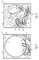
- FIG. 1 is a partially broken away rear perspective view of a commercial clothes dryer embodying the invention;
- FIG. 2 is a sectioned front view of the clothes dryer;
- FIG. 3 is a sectioned rear view of the clothes dryer; and
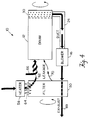
- FIG. 4 is a diagrammatical view of the air flow through the clothes dryer.
- Now, referring generally to the drawings where like reference designations refer to like or similar parts throughout the several views, a
clothes dryer 10 includes aclothes drum 12 havingperforations 40 circumferentially around afront annulus 30. Ablower 16 draws air fromperforations 40 via aduct 24 which has amouth 28 which is spacedly positioned adjacent to a portion ofannulus 30. Even thoughdrum 12 is rotated, some ofperforations 40 are always adjacent tomouth 28 such that air is constantly being drawn fromdrum 12. The air fromblower 16 is forced into one side orcompartment 84 ofplenum 72 from where it flows under pressure throughlint screen 50 to the other side orcompartment 86. The air is exhausted throughexhaust port 88. The lint in the air is collected onlint screen 50 withinplenum 72 and is then rotated onscreen 50 over toburners 58 where it is incinerated. There is aclearance seal 90 betweenlint screen 50 and thesegments plenum 72, but it does not need to be close tolerance because leakage air is drawn back intodrum inlet 46 asrecirculation air 70 rather than being exhausted. In other words, theexhaust air 89 is substantially free of lint even though air may leak fromplenum 72 without passing through the portion oflint screen 50 that passes throughplenum 72. - Now, referring specifically to FIG. 1, a partially broken-away rear perspective view of commercial gas operated
clothes dryer 10 showstumbler drum 12 located withindryer box 14 or outer casing. In conventional manner, clothes are inserted intumbler drum 12 through a door (not shown) at the front, and thentumbler drum 12 is axially rotated by suitable means such asbelt 13 driven by motor 15 (FIG. 2) while hot drying air is circulated throughtumbler drum 12. The circulation of air is effected byblower 16 which is located withinblower shroud 18 which is positioned behind the outsiderear wall 20 ofdryer box 14. More specifically,blower 16, which is also shown in FIG. 3, is rotated by suitable drive means and theblades 22 force air laterally throughblower shroud 18. Air is drawn to blower 16 from tumblerdrum exhaust duct 24 which communicates at the back withblower shroud 18.Exhaust duct 24 extends longitudinally forward along the underside oftumbler drum 12 and communicates withsuction duct 26 or chamber at the front ofdrum 12. - Now referring also to FIG. 2,
suction duct 26 has an arcuate top opening 28 or mouth that conforms with and is positioned in close spaced relationship with aperforated annulus 30 oftumbler drum 12.Suction duct 26 has ahollow cavity 32 that communicates withexhaust duct 24 such that air drawn fromcavity 32 byblower 16 intoexhaust duct 24 creates a slightly negative pressure along an arcuate section of theperforated annulus 30 adjacent to opening 28. Thefront 34 ofdryer box 14 is substantially sealed by the door, and apartition 36 substantially seals the mid-portion 38 oftumbler drum 12 todryer box 14 such that most of the air being drawn or sucked intoopening 28 derives or is drawn from the interior oftumbler drum 12 throughperforations 40 which are instantaneously situated adjacent thereto. More specifically, even thoughtumbler drum 12 rotates, there areperforations 40 around the entire circumference ofperforated annulus 30 such that in all rotational orientations oftumbler drum 12, there areperforations 40 which are closely adjacent to theopening 28 or mouth ofsuction duct 26 so that air is continuously drawn fromtumbler drum 12. As shown in FIG. 2,rollers 42 are provided to support thefront 34 oftumbler drum 12 asmotor 15drives belt 13 to rotatetumbler drum 12.Partition 36 is generally a panel that is affixed todryer box 14 around the outside and has an interiorcircular aperture 43 through whichtumbler drum 12 longitudinally extends. Preferably, a suitable slip gasket may be provided to sealdrum 12 to partition 36 so as to increase the suction by whichsuction duct 26 draws air from the interior oftumbler drum 12. Aflange 44 is attached to thefront 34 oftumbler drum 12. - Still referring to FIG. 1 and also to FIG. 3, the air being sucked or drawn outwardly through
perforations 40 bysuction duct 26 is replaced by air being drawn inwardly throughdrum inlet 46 that here is a rectangular port at the top of backstationary wall 48 which covers the rear oftumbler drum 12. A cylindrical stainlesssteel lint screen 50 or filter surrounds a centralrear region 52 behindtumbler drum 12. Althoughwall 48 is stationary,lint screen 50 is connected or coupled totumbler drum 12 such that it rotates withtumbler drum 12. Therear edge 56 oflint screen 50 seals to therear wall 20 ofdryer box 14 by seating against a running surface (not shown) of the rear wall. - Air is drawn by
blower 16 intodrum inlet 46 along three general paths. First, a plurality oftubular gas burners 58 are axially positioned in an arc withinburner box 60 along an outside sector oflint screen 50 as shown. A gaseous fuel including primary air is introduced by suitable means intotubular burners 58, andburner box 60 communicates with a vent (not shown) in therear wall 20 through which secondary combustion air is drawn. In operation, the flow of air intodrum inlet 46 drawscombustion products 62 fromburner box 60 thereby operatingburners 58 in induced draft. Theflames 64 fromburners 58 fire onto rotatinglint screen 50 thereby incinerating lint as will be described later herein. - The second path for air into
drum inlet 46 is through inlet ports (not shown) in therear wall 20 ofdryer box 14 outside the circumference oflint screen 50. Thisfresh air 66 mixes with the combustion products fromburners 58 as shown best in FIG. 3 thereby limiting the temperature at which air entersdrum inlet 46. More specifically,burners 58 are located towards the bottom ofregion 52, and druminlet 46 is located towards the top ofregion 52 such that there is adequate mixing length forcombustion products 62 andfresh air 66 thereby providinginlet air 68 having a limited uniform temperature. The ratio of mixing air is selected so as to provide a suitable temperature. - The third path for air into
drum inlet 46 isrecirculation air 70 leaked fromplenum 72. More specifically, referring to FIGS. 1 and 3,blower 16 forces air from tumblerdrum exhaust duct 24 laterally throughblower shroud 18 which has anexit port 74 intoplenum 72.Blower shroud 18 is outside ofrear wall 20 andplenum 72 is inside, so the exhaust air flows axially inward throughexhaust port 74 intoplenum 72. As shown best in FIG. 3,plenum 72 is an enclosure which includes two arcuate orsemi-circular segments respective cover Segments gap 82 through whichannular lint screen 50 rotates with the lint screen extending outwardly from or above covers 80 and 81. Stated differently,segment 76 is stationarily positioned on the outside oflint screen 50 defining afirst compartment 84 or cavity, andsegment 78 is stationarily positioned inregion 52 on the inside oflint screen 50 thereby defining asecond compartment 86 or cavity.Compartments blower shroud 18 entersfirst compartment 84 on the outside oflint screen 50 throughexit port 74. Such air is lint laden and, under positive pressure, it flows throughlint screen 50 intosecond compartment 86 on the inside oflint screen 50. The airborne lint is deposited or collected on the outside oflint screen 50 as it rotates throughgaps 82. Air exitssecond compartment 86 ofplenum 72 throughexhaust port 88 which conveys theexhaust air 89 throughrear wall 20. There is aclearance seal 90 betweensegments lint screen 50, so some air leaks fromplenum 72 without enteringsecond compartment 86. A close tolerance seal is not required because this leakage air is withinbox 14 and is drawn intodrum inlet 46 thereby providingrecirculation air 70 fordryer 10. Preferably,recirculation air 70 may comprise approximately 20 percent of the air enteringdrum inlet 46.Plenum 72 is so arranged, however, that air forced intosegment 78 for exhaust throughexhaust port 88 has passed throughlint screen 50 thereby removing airborne lint. The lint collected onlint screen 50 withinplenum 72 is then conveyed on the rotating lint screen over toflames 64 ofburners 58 where the lint is incinerated. - Referring to FIG. 4, a diagrammatical view of the air flow system of
dryer 10 is shown.Blower 16 draws air from theperforated annulus 30 ofdrum 12 viaduct 24, and the air is exhausted throughfilter 50 where the airborne lint is collected. The sucking of air from theperforated annulus 30 ofdrum 12 draws air from three different sources into the back ofdrum 12. First, there arecombustion products 62 that are drawn from the heater, hereburner 58, which operates in an induced draft. Second, there isfresh air 66 which mixes with and thereby cools thecombustion products 62 to a suitable uniform temperature before being drawn intodrum 12. Third, there isleakage air 70 fromfilter 50 which recirculates throughdrum 12, and, for example, comprises 20 percent of the air input through the drum inlet. Thelint screen 50 or filter rotates withdrum 12 such that lint collected from the exhaust air is rotated around to theheater flames 64 where it is incinerated. - In accordance with the invention,
blower 16 is upstream fromlint screen 50 or, stated differently, the lint filter is on the high pressure side ofblower 16. Further, theblower 16 is at the outlet of thetumbler drum 12. Accordingly, the air passing through thelint filter 50 is pressurized such that there is no requirement for a second blower --one to recirculate and one to exhaust. Also, it is not necessary forclearance seal 90 betweenlint screen 50 and covers 80 and 81 to be of close tolerance because substantially all of the air that goes intosecond compartment 86 flows throughlint screen 50 before being exhausted throughexhaust port 88. Accordingly,exhaust air 89 is substantially lint-free. On the other hand, any air that leaks throughclearance seal 90 without having the lint removed bylint screen 50 is retained withindryer box 14 and is drawn intodrum inlet 46 as recirculation air. Accordingly, lint is effectively removed from the exhaust air, and air that leaks from the filtering process is enclosed bydryer box 14 and drawn back intotumbler drum 12 throughdrum inlet 46 as recirculation air. In other words, theexhaust air 89 is suitably filtered bylint screen 50 at a localized region withinplenum 72 without the requirement of having a close tolerance seal to ensure that allair exiting drum 12 is passed throughlint screen 50. The leakage air is not exhausted, but rather is recirculated throughdrum 12. - This concludes the Description of the Preferred Embodiment. A reading of it by those skilled in the art will bring to mind many alterations and modifications without departing from the scope of the invention. Accordingly, it is intended that the scope of the invention be limited only by the appended claims.
Claims (5)
- A clothes dryer comprising:
a clothes drum (12) having perforations (40);
a substantially cylindrical rotary lint screen (50) extending from said drum (12) and having an inside and an outside;
a blower (16) having an inlet and an outlet and providing an air flow through said drum (12);
means (24, 18, 72) for directing output air from said drum (12) through said screen (50) to collect lint from said air onto said screen; and
means (58) for burning said lint on said lint screen; characterized in that:
said blower (16) is connected between said perforations (40) and said lint screen (50) with the inlet being coupled to the perforations (40) and the outlet being directed to said lint screen (50), wherein air is drawn by negative pressure from the drum (12) through the perforations (40) and then passes through the blower (16); and
the said means (24, 18, 72) for directing output air comprises a plenum (72) having a first compartment (84) on the outside of said lint screen (50) and a second compartment (86) with an exhaust port (88) on the inside of said screen (50), said air being directed from said first compartment (84) through said lint screen (50) to said exhaust port (88) in said second compartment (86), such that lint in said air is collected on the high pressure blower side of said screen. - The dryer recited in Claim 1 wherein said perforations (40) are located in a front annulus (30) of said drum (12), said dryer further comprising a duct (24) coupled between said annulus (30) and said blower (16).
- A clothes dryer according to Claim 1, wherein said perforations (40) are located in a front annulus (30) of said drum (12) and said lint screen (50) is coupled to said drum (12) and extends rearwardly therefrom;
further comprising:
means (13, 15) for axially rotating said drum (12) and said lint screen (50);
a duct (24) having one end communicating with said inlet of said blower (16) and an opposite end spaced adjacent to at least a portion of said perforated annulus (30) for drawing air from said drum (12); and
said means (58) for burning said lint, comprising a stationary burner positioned adjacent to a portion of said lint screen (50) wherein lint collected on said screen (50) is rotated on said screen past said burner (58) for incineration. - The dryer recited in Claim 3 further comprising an air inlet (46) at the rear of said drum (12), said blower (16) providing an induced draft on said burner (58) by drawing air from said burner (58) into said drum inlet (46), through said drum (12) and out through said perforated annulus (30).
- A method of drying clothes in a clothes dryer (10) having a clothes drum (12) with a perforated front annulus (30) and a rear air inlet (46); the dryer further having a cylindrical lint screen filter (50) at the rear of said drum (12), and a stationary burner (58) adjacent to a portion of said lint screen filter (50), comprising the steps of:
locating said clothes to be dried in the clothes drum (12);
activating the burner (58);
rotating the clothes drum (12) and the lint screen filter (50);
providing a negative pressure outside the perforations (40) of the front annulus (30) so as to draw air into the drum (12) through the rear air inlet (46) and out through the perforations (40);
pressurising air drawn from the perforations (40) in a blower (16) and directing the air under positive pressure radially inwardly through the lint screen filter (50); and
exhausting at least a portion of the air that is directed radially inwardly through the lint screen filter (50).
Applications Claiming Priority (2)
| Application Number | Priority Date | Filing Date | Title |
|---|---|---|---|
| US257663 | 1988-10-14 | ||
| US07/257,663 US4899462A (en) | 1988-10-14 | 1988-10-14 | Lint burning clothes dryer |
Publications (3)
| Publication Number | Publication Date |
|---|---|
| EP0364286A2 EP0364286A2 (en) | 1990-04-18 |
| EP0364286A3 EP0364286A3 (en) | 1990-05-30 |
| EP0364286B1 true EP0364286B1 (en) | 1994-06-01 |
Family
ID=22977222
Family Applications (1)
| Application Number | Title | Priority Date | Filing Date |
|---|---|---|---|
| EP89310510A Expired - Lifetime EP0364286B1 (en) | 1988-10-14 | 1989-10-13 | Lint burning clothes dryer |
Country Status (3)
| Country | Link |
|---|---|
| US (1) | US4899462A (en) |
| EP (1) | EP0364286B1 (en) |
| DE (1) | DE68915677T2 (en) |
Families Citing this family (19)
| Publication number | Priority date | Publication date | Assignee | Title |
|---|---|---|---|---|
| US5062219A (en) * | 1991-02-12 | 1991-11-05 | Speed Queen Company | Air flow apparatus for clothes dryer |
| US6324771B1 (en) * | 2000-02-08 | 2001-12-04 | Alliance Laundry Systems Llc | Drying tumbler with temperature limiting air flow bypass |
| DE10123074A1 (en) * | 2001-05-10 | 2002-11-14 | Monforts Textilmaschinen Gmbh | Device for the heat treatment of a web |
| US6785981B1 (en) | 2003-02-19 | 2004-09-07 | In-O-Vate Technologies | Restriction detecting systems for clothes dryer exhaust systems |
| KR20060036267A (en) * | 2004-10-25 | 2006-04-28 | 삼성전자주식회사 | Clothes dryer |
| DE102005023442A1 (en) * | 2005-05-20 | 2006-11-30 | BSH Bosch und Siemens Hausgeräte GmbH | Household appliance for the care of laundry, in particular tumble dryer |
| KR101253152B1 (en) * | 2006-04-17 | 2013-04-10 | 엘지전자 주식회사 | dryer |
| US7886458B2 (en) * | 2006-12-22 | 2011-02-15 | G.A. Braun Inc. | Lint collection apparatus and system for fabric dryers |
| KR20100080415A (en) | 2008-12-30 | 2010-07-08 | 엘지전자 주식회사 | Laundry machine |
| KR20100129117A (en) | 2009-05-28 | 2010-12-08 | 엘지전자 주식회사 | Washing machine |
| KR101692726B1 (en) | 2009-05-28 | 2017-01-04 | 엘지전자 주식회사 | Laundry machine |
| KR20100129161A (en) | 2009-05-28 | 2010-12-08 | 엘지전자 주식회사 | Washing machine |
| KR101689604B1 (en) | 2009-05-28 | 2017-01-09 | 엘지전자 주식회사 | Laundry machine |
| US9828715B2 (en) | 2009-05-28 | 2017-11-28 | Lg Electronics Inc. | Laundry maching having a drying function |
| US9920469B2 (en) * | 2014-05-20 | 2018-03-20 | Haier Us Appliance Solutions, Inc. | Dryer appliance and a method for operating a dryer appliance |
| CN111041801B (en) * | 2018-10-15 | 2021-08-10 | 广东美的白色家电技术创新中心有限公司 | Filter screen assembly, base assembly, clothes dryer and washing and drying integrated machine |
| US10765974B2 (en) * | 2019-01-25 | 2020-09-08 | Haier Us Appliance Solutions, Inc. | Lint collection assembly for a dryer appliance |
| US11174586B2 (en) * | 2019-09-10 | 2021-11-16 | Haier Us Appliance Solutions, Inc. | Vortex dryer appliance |
| CN112522929B (en) * | 2019-09-17 | 2024-07-23 | 青岛胶州海尔洗涤电器有限公司 | A method for cleaning wire scraps at electric heating wire of clothes dryer and clothes dryer |
Family Cites Families (5)
| Publication number | Priority date | Publication date | Assignee | Title |
|---|---|---|---|---|
| GB620906A (en) * | 1946-02-20 | 1949-03-31 | Bendix Home Appliances Inc | Clothes dryer with lint burner |
| US3102008A (en) * | 1958-01-23 | 1963-08-27 | Gen Motors Corp | Domestic appliance |
| US3306596A (en) * | 1965-01-28 | 1967-02-28 | American Gas Ass | Heated-gas system with apparatus for removing gas-borne foreign bodies |
| US4665628A (en) * | 1986-03-31 | 1987-05-19 | Raytheon Company | Recuperative clothes dryer with enhanced recirculation and air flow |
| US4669199A (en) * | 1986-03-31 | 1987-06-02 | Raytheon Company | Clothes dryer with a lint incinerator |
-
1988
- 1988-10-14 US US07/257,663 patent/US4899462A/en not_active Expired - Fee Related
-
1989
- 1989-10-13 EP EP89310510A patent/EP0364286B1/en not_active Expired - Lifetime
- 1989-10-13 DE DE68915677T patent/DE68915677T2/en not_active Expired - Fee Related
Also Published As
| Publication number | Publication date |
|---|---|
| DE68915677D1 (en) | 1994-07-07 |
| DE68915677T2 (en) | 1994-11-03 |
| US4899462A (en) | 1990-02-13 |
| EP0364286A3 (en) | 1990-05-30 |
| EP0364286A2 (en) | 1990-04-18 |
Similar Documents
| Publication | Publication Date | Title |
|---|---|---|
| US4899462A (en) | Lint burning clothes dryer | |
| US3969070A (en) | Clothes dryer with heat reclaimer | |
| US4689896A (en) | Clothes dryer and laundry system | |
| US2827276A (en) | Laundry dryer | |
| US3377056A (en) | Drying apparatus | |
| US5819437A (en) | Quiet operating industrial dryer with a combustion burner grate | |
| US4669199A (en) | Clothes dryer with a lint incinerator | |
| EP1123999B1 (en) | Drying tumbler with temperature limiting air flow bypass | |
| US20170336142A1 (en) | Dryer for a textile web, with improved hot-air supply | |
| CN101314914B (en) | Dryer roller support | |
| US5722180A (en) | Apparatus for drying a wet paper web | |
| US2958139A (en) | Clothes drier | |
| KR102346958B1 (en) | Hot air spraying device for drying high water content sludge | |
| US2964851A (en) | Drier lint trap | |
| US4550509A (en) | Air guide arrangement for a drum-type drier | |
| US2791039A (en) | Apparatus for web drying | |
| GB2181669A (en) | Gas filter | |
| JP4545566B2 (en) | Commercial dryer | |
| US4091546A (en) | Laundry machine air vent | |
| US3313039A (en) | Cooling arrangement for drum dryer fan bearings | |
| US3974573A (en) | Dryer having improved heating system | |
| KR100468137B1 (en) | A washer-dryer | |
| US3329415A (en) | Blower cooler | |
| JP3482682B2 (en) | Clothes dryer | |
| CN218722795U (en) | Rotation type water trap |
Legal Events
| Date | Code | Title | Description |
|---|---|---|---|
| PUAI | Public reference made under article 153(3) epc to a published international application that has entered the european phase |
Free format text: ORIGINAL CODE: 0009012 |
|
| PUAL | Search report despatched |
Free format text: ORIGINAL CODE: 0009013 |
|
| AK | Designated contracting states |
Kind code of ref document: A2 Designated state(s): DE GB |
|
| AK | Designated contracting states |
Kind code of ref document: A3 Designated state(s): DE GB |
|
| 17P | Request for examination filed |
Effective date: 19901004 |
|
| 17Q | First examination report despatched |
Effective date: 19920203 |
|
| GRAA | (expected) grant |
Free format text: ORIGINAL CODE: 0009210 |
|
| AK | Designated contracting states |
Kind code of ref document: B1 Designated state(s): DE GB |
|
| REF | Corresponds to: |
Ref document number: 68915677 Country of ref document: DE Date of ref document: 19940707 |
|
| PLBE | No opposition filed within time limit |
Free format text: ORIGINAL CODE: 0009261 |
|
| 26N | No opposition filed | ||
| PGFP | Annual fee paid to national office [announced via postgrant information from national office to epo] |
Ref country code: GB Payment date: 19991103 Year of fee payment: 11 |
|
| PGFP | Annual fee paid to national office [announced via postgrant information from national office to epo] |
Ref country code: DE Payment date: 19991108 Year of fee payment: 11 |
|
| PG25 | Lapsed in a contracting state [announced via postgrant information from national office to epo] |
Ref country code: GB Free format text: LAPSE BECAUSE OF NON-PAYMENT OF DUE FEES Effective date: 20001013 |
|
| GBPC | Gb: european patent ceased through non-payment of renewal fee |
Effective date: 20001013 |
|
| PG25 | Lapsed in a contracting state [announced via postgrant information from national office to epo] |
Ref country code: DE Free format text: LAPSE BECAUSE OF NON-PAYMENT OF DUE FEES Effective date: 20010703 |