EP0364147B1 - A fuel injection system - Google Patents
A fuel injection system Download PDFInfo
- Publication number
- EP0364147B1 EP0364147B1 EP19890310105 EP89310105A EP0364147B1 EP 0364147 B1 EP0364147 B1 EP 0364147B1 EP 19890310105 EP19890310105 EP 19890310105 EP 89310105 A EP89310105 A EP 89310105A EP 0364147 B1 EP0364147 B1 EP 0364147B1
- Authority
- EP
- European Patent Office
- Prior art keywords
- fuel
- gas
- chamber
- valve
- pressure
- Prior art date
- Legal status (The legal status is an assumption and is not a legal conclusion. Google has not performed a legal analysis and makes no representation as to the accuracy of the status listed.)
- Expired - Lifetime
Links
Images

Classifications
-
- F—MECHANICAL ENGINEERING; LIGHTING; HEATING; WEAPONS; BLASTING
- F02—COMBUSTION ENGINES; HOT-GAS OR COMBUSTION-PRODUCT ENGINE PLANTS
- F02M—SUPPLYING COMBUSTION ENGINES IN GENERAL WITH COMBUSTIBLE MIXTURES OR CONSTITUENTS THEREOF
- F02M67/00—Apparatus in which fuel-injection is effected by means of high-pressure gas, the gas carrying the fuel into working cylinders of the engine, e.g. air-injection type
- F02M67/02—Apparatus in which fuel-injection is effected by means of high-pressure gas, the gas carrying the fuel into working cylinders of the engine, e.g. air-injection type the gas being compressed air, e.g. compressed in pumps
-
- F—MECHANICAL ENGINEERING; LIGHTING; HEATING; WEAPONS; BLASTING
- F02—COMBUSTION ENGINES; HOT-GAS OR COMBUSTION-PRODUCT ENGINE PLANTS
- F02D—CONTROLLING COMBUSTION ENGINES
- F02D7/00—Other fuel-injection control
- F02D7/02—Controlling fuel injection where fuel is injected by compressed air
-
- F—MECHANICAL ENGINEERING; LIGHTING; HEATING; WEAPONS; BLASTING
- F02—COMBUSTION ENGINES; HOT-GAS OR COMBUSTION-PRODUCT ENGINE PLANTS
- F02M—SUPPLYING COMBUSTION ENGINES IN GENERAL WITH COMBUSTIBLE MIXTURES OR CONSTITUENTS THEREOF
- F02M57/00—Fuel-injectors combined or associated with other devices
- F02M57/02—Injectors structurally combined with fuel-injection pumps
- F02M57/022—Injectors structurally combined with fuel-injection pumps characterised by the pump drive
- F02M57/028—Injectors structurally combined with fuel-injection pumps characterised by the pump drive pneumatic
-
- F—MECHANICAL ENGINEERING; LIGHTING; HEATING; WEAPONS; BLASTING
- F02—COMBUSTION ENGINES; HOT-GAS OR COMBUSTION-PRODUCT ENGINE PLANTS
- F02M—SUPPLYING COMBUSTION ENGINES IN GENERAL WITH COMBUSTIBLE MIXTURES OR CONSTITUENTS THEREOF
- F02M67/00—Apparatus in which fuel-injection is effected by means of high-pressure gas, the gas carrying the fuel into working cylinders of the engine, e.g. air-injection type
- F02M67/10—Injectors peculiar thereto, e.g. valve less type
- F02M67/12—Injectors peculiar thereto, e.g. valve less type having valves
-
- F—MECHANICAL ENGINEERING; LIGHTING; HEATING; WEAPONS; BLASTING
- F02—COMBUSTION ENGINES; HOT-GAS OR COMBUSTION-PRODUCT ENGINE PLANTS
- F02M—SUPPLYING COMBUSTION ENGINES IN GENERAL WITH COMBUSTIBLE MIXTURES OR CONSTITUENTS THEREOF
- F02M69/00—Low-pressure fuel-injection apparatus ; Apparatus with both continuous and intermittent injection; Apparatus injecting different types of fuel
- F02M69/08—Low-pressure fuel-injection apparatus ; Apparatus with both continuous and intermittent injection; Apparatus injecting different types of fuel characterised by the fuel being carried by compressed air into main stream of combustion-air
-
- F—MECHANICAL ENGINEERING; LIGHTING; HEATING; WEAPONS; BLASTING
- F02—COMBUSTION ENGINES; HOT-GAS OR COMBUSTION-PRODUCT ENGINE PLANTS
- F02B—INTERNAL-COMBUSTION PISTON ENGINES; COMBUSTION ENGINES IN GENERAL
- F02B1/00—Engines characterised by fuel-air mixture compression
- F02B1/02—Engines characterised by fuel-air mixture compression with positive ignition
- F02B1/04—Engines characterised by fuel-air mixture compression with positive ignition with fuel-air mixture admission into cylinder
Definitions
- This invention relates in general to a fuel injection system for an automotive type internal combustion engine. More particularly, it relates to the construction of a fuel injector in which fuel and air or other gas are premixed in a chamber in the injector prior to being discharged into the engine combustion chamber, a dwell period being provided prior to the injection so as to allow for mixing and, in the case of a liquid fuel, for evaporation of the fuel charge in contact with the gas, resulting in a premixed, rich fuel/air charge that is injected with the fuel at least partially in a gaseous state.
- a fuel injector of this kind is known from US-A-1,560,025, which discloses a fuel injector assembly including a hollow body having a main fuel/gas mixing chamber open at both ends and ventable to ambient pressure so as initially to contain a gas at essentially ambient pressure, a control valve normally closing one end of the chamber as well as an outlet from the body and actuatable to an open position to permit ejection of a fuel/gas mixture from the chamber and body, a first source of fuel and a second source of gas under pressure each separably connectable to the chamber through the body, and means movable between open and closed positions for controlling admission of each of the sources to the chamber, the latter means being movable in a manner to first admit fuel to the chamber for mixing with the gas therein and after a time delay to admit the gas under pressure to the chamber to further mix the fuel and gas in the chamber and eject the mixture from the chamber body.
- the fuel is introduced adjacent the control valve and opening and closing of the inlets and outlet is effected mechanically by an external
- Igashira et al, US-A-4,465,050 discloses a manifold injector system including an air pump and a fuel pump which deliver their respective fluids to an injector having a single pulsed solenoid that controls only fuel flows, air being controlled by a separate valve.
- the air and fuel pulses are simultaneous, however, and there is no dwell period after the fuel and air are introduced together to permit time for the fuel to evaporate before being injected into the engine.
- McKay, US-A-4,554,945 shows a construction in which fuel is first introduced into a metering chamber and then air is admitted by a solenoid and air pressure to close the fuel inlet and outlet ports. However, again, there is no mixing of the air and fuel with a timed delay sufficient to permit evaporation of the fuel and further mixing prior to injection into the engine.
- Tsummura et al, US-A-4,381,077 provides an injector wherein air is introduced simultaneously with fuel and these are combined in a mixing chamber wherefrom they are displaced by a piston. While there is a mixing and a dwell period, the mixture is not displaced by engine compressed gas or air admitted to evaporate the fuel during the mixing process.
- BE-A-738,280 discloses apparatus for working materials in which the working pressure is generated by combustion of fuel in a cylinder, the fuel being first metered into an admission chamber of a mixer containing residual air under pressure from the previous cycle. An inlet valve from the mixer to the cylinder is opened, and the mixture of fuel with further air is forced into the cylinder by admitting further compressed air into the mixer. The inlet valve to the cylinder is then closed, leaving the mixing chamber containing compressed air.
- the fuel and gas sources are each connectable through the body of the injector to the end of the chamber remote from the control valve, the means for controlling the admission of fuel and gas are selectively operable and the control valve is opened by the admission of gas under pressure to the chamber to eject the mixture from the chamber and body.
- an electrical control system comprising driver circuits arranged to actuate the respective inlet valves for the supply of fuel and of gas/air to the injectors serving the respective combustion chambers of an engine so as to effect the supply to the injectors in a manner establishing a time interval between introduction of the fuel and discharge of the fuel/air or fuel/gas mixture into the combustion chambers.
- the invention provides a method of supplying and discharging a fuel and gas mixture into and from an automotive type fuel injector that is biased to a closed position comprising the steps of, first, connecting a central chamber in the injector to gas at ambient pressure level, secondly, supplying the chamber with fuel at the end remote from its outlet to mix with the gas to form at least a partially combustible mixture charge, thirdly, holding the fuel/gas mixture charge in the chamber for a period sufficient to allow evaporation of the fuel and further mixing of the fuel and gas, and, fourthly, applying further gas to the chamber at a sufficient pressure level to enhance penetration of the gas into the fuel and evaporation of the fuel, the further gas being supplied at a sufficient pressure to cause a normally-closed outlet valve from the chamber to open and to effect discharge of the fuel/gas mixture charge from the injector.
- the gas used to eject the mixture may be compressed air or compressed gas from an engine cylinder during its compression stroke. Subsequent to cessation of supply of the gas under pressure to the chamber and closure of the outlet valve the chamber should be vented to an ambient pressure level, and for this purpose the apparatus may include means for connecting the gas inlet to air or gas at ambient pressure.
- the invention relates generally to air or gas forced fuel injection systems for gasoline engines of the type in which electronically controlled devices, such as solenoid valves, are sued as actuators for both fuel and air control.
- electronically controlled devices such as solenoid valves
- Other devices such as piezoelectric actuators can however be used instead of solenoids.
- fuel injection system to be described is intended primarily for direct fuel injection, it is also applicable to port injection.
- Compressed air, or cylinder compression gas in another embodiment is used for fuel injection and atomisation.
- one of the main features of the system is the fact that fuel charge metering and fuel injection are separated by a time interval during which the fuel charge is in contact with air or gas and can evaporate so that when the injection is made, a premixed, rich fuel/air or fuel/gas charge is injected with the fuel at least partially in gaseous state.
- Important items in the system are a set of injectors, one per engine cylinder, which are usually installed directly in the cylinder head, and where cylinder compressed air is employed, a set of charging valves, also one per engine cylinder, and also usually installed directly in the cylinder head. Fuel and compressed air or gas are supplied to each injector by separate fuel and air or gas supply systems.
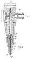
- Figure 1 shows a fuel injector assembly 10 that includes a shell or body 12 containing a central air/gas and fuel mixing chamber 14.
- the chamber extends longitudinally along the axis of the injector assembly and at its lower end is enlarged at 16 to contain a fuel injector valve 18.
- the valve reciprocates in a valve body 20 between open and closed positions, and has a nozzle or tip 22 seated against the body by a spring 24.
- Side ports 26 communicate the fuel/air mixture charge in mixing chamber 14 to the tip of the injector valve along the channel or passage 28 containing the stem of the valve.
- valve 30 is a fuel control valve. It normally closes a supply passage 34 communicating with the mixing chamber 14 at one end and with a fuel supply F, as indicated, at its other end.
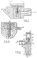
- Valve 32 is an air control valve. It normally blocks the passage of compressed air A from a passage 35 ( Figure. 2) and a chamber 36 into the mixing chamber 14 through a connecting passage 38.
- Figure 2 further illustrates an electrical input 40 to both the fuel and air solenoids.
- the mixing chamber 14 When air is employed as the mixing and pressurising gas the mixing chamber 14 will always contain air.
- the mixing chamber 14 is vented to the outside so that its residual pressure always drops after the end of injection to a low level approximately equal to atmospheric pressure.
- the air control valve 32 has an axial channel 42 extending along its length with a calibrated orifice 44 at its tip in communication with the passage 38 and chamber 14. Between injections, the channel 42 connects the mixing chamber 14 with the inside of the solenoid, which is vented to the outside through the space 46 between the top of the valve and the solenoid housing and around the valve stem and out via a passage 48 to the intake of the air compressor or to the intake of the engine.
- the solenoids in this case would be controlled by means of an electronic control system which supplies the solenoids with voltage signals of variable width and timing, the signals being fed through the connector 40 shown in Figure 2.
- fuel valve 30 opens, fuel will be metered into the mixing chamber 14.
- the metered fuel quantity would be determined by the duration of fuel control valve opening, size of the orifice and the supply of fuel pressure. Usually, it would be controlled by controlling the solenoid pulse width.
- the fuel After the introduction of the fuel into chamber 14, the fuel will stay in the air filled chamber for a substantial portion of the engine cycle. This provides a time interval in which the fuel is exposed to the air and can evaporate before the mixture is injected into the engine. It permits time for the fuel to penetrate the air in the chamber.
- the air control valve 32 opens, a charge of compressed air fills the mixing chamber 14 to effect a further mixing and evaporation of the fuel by a penetration of the air into the fuel, and also opens the normally closed injector valve 22 to expel the premixed fuel/air charge past the valve tip.
- the timing of fuel injection can be controlled by controlling the timing of the air control solenoid pulse. Varying the compressed air pressure also can vary injection rate and fuel penetration. The injection ends when the air control solenoid or actuator is deactivated and the air control valve 32 closes.
- the mixing chamber 14 will be vented to the outside to the intake of the air compressor or to the intake of the engine through the calibrated orifice 44 in the air control valve 32 and therefrom through the vent passage 48. This once again results in the mixing chamber 14 being filled with air at ambient or atmospheric pressure level.
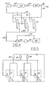
- FIG. 4 shows schematically an overall diagram of a compressed air and fuel supply arrangement for a system having three injectors 50.
- a fuel pump 52 draws fuel from a reservoir 54 and delivers it under pressure through a pressure regulator 56 to a common fuel supply rail 58 to which all three of the injectors 50 are connected. Any excess fuel is returned to the reservoir 54 via the line 57.
- a compressor 60 draws atmospheric air A through an intake 62 and pumps it under pressure into a compressed air reservoir or accumulator 64.
- a check valve 66 on the inlet and a solenoid valve 68 on the outlet which is open only during engine operation, maintain the air pressure in reservoir 64 when the engine is not running.
- compressed air would be discharged from the reservoir 64 through the open solenoid valve 68 and supplied under pressure through a controllable pressure regulator 70 to a common air supply rail 72 to which all three injectors 50 are connected in parallel by connecting lines 74. Varying the air pressure in the common rail 72 will vary the fuel injection rate and fuel spray penetration, as described previously in connection with the embodiment shown in Figures 1-3.
- the vented air in air control valve 32 would be returned to the inlet to the compressor by the line 48.
- the three injectors in this case are controlled by an electronic control system that would receive the operator's demand signal and determine the needed solenoid voltage pulse width and timing necessary to supply the engine with the required fuel quantity at the right time in the engine cycle.
- a voltage pulse of proper duration and timing would be sent to each solenoid and, in principle, each solenoid would require a separate driving circuit. It is possible, however, to reduce the number of driving circuits by using a single solenoid driver to drive two solenoid simultaneously.
- An example of such an arrangement is shown diagrammatically in Figure 5 where three solenoid drivers 80, 82, 84 are used to drive six solenoids, 1F, 2F, 3F, 1A, 2A, 3A, associated with the three injectors numbered I1 to I3.
- Each of the drivers 80, 82, 84 would drive an air control solenoid for example 1A, in one injector and a fuel control solenoid e.g., 2F in another one.
- a fuel control solenoid e.g. 2F in another one.
- activation of driver 84 would energise solenoids 2A and 3F, resulting in injection from injector No.2 and fuel metering in injector No.3.
- Activation of driver 82 therefore, leads to injection from injector No. 3 and metering in injector No.1. It will be clear, therefore, that the dwell between the injection of the fuel and the opening of the air control valve is clearly provided for.
- the solenoid valves would be designed so that the minimum pulse width necessary for the air controlled solenoid would never be shorter than the required fuel controlled solenoid pulse.
- the time interval between fuel metering or entering into the chamber 14 and the fuel injection event in each injector would be equal to one-third of the cycle. It is clear, however, that with a slightly different arrangement, this timed interval could be two-thirds of the cycle, for example, thus giving the fuel more time for evaporation in the mixing chamber 14.
- the pairs of simultaneously energized solenoid actuators should be: 1A and 3F, 2A and 1F, 3A and 2F. It is clear, also, that each pair of simultaneously energized solenoids could be connected in series, rather than in parallel, as shown.
- the fuel quantity metered by the fuel control solenoid valve is determined by the fuel flow rate through the valve orifice and the duration of the valve opening.
- Q qt (1)
- t duration of valve opening in ms
- the flow rate q is a function of the orifice area and the pressure differential across the orifice. If the orifices in all solenoid valves are made with very high accuracy, their areas are equal. In a given system, the pressure differentials are also equal for all orifices. In such a system q can be considered a system constant.
- valve opening t is a function of the solenoid control pulse width.
- t t c - t a + t d (2)
- t x correction term
- the values of t and t c are the same for all fuel control solenoids for a given fuel quantity demand.
- the value of correction term t x is, in principle, different for each solenoid and is selected so as to assure equal fuel delivery to all cylinders.
- the value of the correction term t x for each individual injector can be determined experimentally during injector bench testing and encoded on the injector in the form of a number, which can be called the injector characteristic number.
- the accuracy with which the control orifices in the solenoid valves are made is not high enough, and the solenoid-to-solenoid differences in orifice areas cannot be disregarded. In this case, the fuel flow rate q in equation (1) cannot be considered a system constant.
- the values of K should be always larger than one (or always less than one).
- the value of the correction factor K for each individual injector can be determined experimentally during injector bench testing and encoded on the injector as part of the same characteristic number which contains information on the correction term t x .
- the controller reads the values of both the correction term t x and the correction factor K and, for a given value of required fuel quantity Q, determines the required control pulse t c from the following algorithm.
- t c Q/Kq + t s + t x (7)
- the manner in which the characteristic number is encoded should permit easy transmission of information on the number to the electronic controller.
- the injector can be equipped with a memory device in which the value of the characteristic number is retained and can be "read" by the controller.
- a microchip memory would be suitable for this purpose, but, since only one number has to be stored, much simpler devices can be used.
- each fuel control solenoid is usually driven by a separate power transistor driver
- cylinder-to-cylinder fuel maldistribution may also be the result of differences between individual solenoid drivers. This deficiency can be corrected in the same manner as in the case of differences between solenoids.
- An additional correction term accounting for the deviation in the characteristic of the driver is introduced into the fuel delivery algorithm, an individual characteristic number is encoded on each driver, and the controller reads the characteristic numbers of all the drivers as well as solenoids and makes proper adjustments in control pulse widths.
- Figs. 1-5 embodiment show the use of compressed air to perform the injection of the fuel/air mixture into the engine.
- Fig. 6 shows a charging valve assembly in which engine gas compressed in the engine cylinders during the compression strokes is used to perform the injection of fuel for improved fuel atomization or both, instead of the compressed air in the Figs. 1-5 embodiment. More specifically, the purpose of each charging valve is to tap the pressure generated in the cylinder during the compression stroke and charge the compressed gas supply system to the predetermined maximum pressure. In the most elementary case, the compressed gas supply system would simply consist of lines connecting each charging valve with one of the injectors.
- Fig. 6 shows an example of a charging valve assembly.
- the assembly actually includes two valves, a normally opened pressure limiting valve 90, and a normally closed check valve 92 that leads to a line 94 connecting the valve to the compressed gas supply system for the injectors.
- the pressure limiting valve 90 is of the poppet type having an upper land 96 sealingly secured to a spring seat 98 for a spring 100.
- the spring would normally maintain the valve 90 open below a predetermined cylinder compression gas pressure level.
- the check valve 92 could be of a known construction and operation having a spring pressed ball 102 closing the passage 104 communicating with the channel or chamber 106.
- the pressure limiting valve 90 During the compression stroke, the pressure limiting valve 90 would initially be open, and as soon as the pressure in the engine cylinder exceeds the residual pressure in the compressed gas supply system, the cylinder pressure would open check valve 92 and the gas supply system would be charged by the engine compression gas to a maximum pressure determined by the preload of the spring 100.
- the pressure force acting on the piston or land 96 of the pressure limiting valve 90 would overcome the force of the spring 100 and close valve 90. It would reopen again in the later part of the expansion stroke when the pressure force acting on the pressure limiting valve drops below the preload of the spring 100.
- the volume above land 96; i.e., the chamber 110 containing the spring 100 is vented to the outside through a vent 112. In some cases, this volume may have to be connected to the engine intake.
- the charging valve can be without the pressure limiting valve 90. In that case, however, the gas supply system would be charged with hot combustion gas.
- FIG. 7 While there are several ways in which the gas forced injection system could be arranged, one is shown diagrammatically in Figure 7 for a three-cylinder engine 4. Fuel and compressed gas would be supplied to the three injectors 120, 122, and 124 associated with the respective cylinder C1, C2, C3 by two separate system.
- a fuel pump 126 In the fuel supply system, a fuel pump 126 would draw fuel from a reservoir 128 and deliver it under pressure via a pressure regulator 127 to a common fuel rail 130 to which all three injectors are connected, excess fuel being retrieved by a return line 129.
- a gas line 132 from one of the charging valve assemblies 5 described in connection with Figure 6 would connect each injector with one of the charging valves.
- each line should be sufficient to store enough compressed gas to perform at least one fuel injection event.
- the injector would be connected with the charging valve installed in a cylinder preceding the given cylinder in the firing order.
- the firing order of the cylinder is 1-2-3; and, thus, the charging valve in cylinder one would feed compressed gas to the injector in cylinder two, while the charging valves in cylinders two and three would feed gas to injectors in cylinders three and one, respectively.
- the gas vented from all the injectors would be returned to the engine intake by a line 133, as indicated.
- FIG 8 Another example of a gas forced injection system is shown in Figure 8, which is essentially the same as that shown in the Figure 4 embodiment, except for the supply of gas to the reservoir 64'.
- all three injectors receive compressed gas from a common rail gas supply system, rather than air.
- the charging valves in all the engine cylinders would feed compressed gas into a common compressed gas reservoir 64' from where it could be discharged through a solenoid valve 68' and a controllable gas pressure regulator 70' into the common gas supply rail 72'.
- the solenoid valve would be open only during engine operation and, therefore, gas pressure in the reservoir would be maintained even when the engine is not running.
- the system operates otherwise as described in connection with the embodiment shown in Figure 4.
- a system similar to the one described above could be used also to improve fuel atomisation.
- Fuel injection systems in which improved fuel atomisation is achieved by injection compressed air into a stream of fuel exiting an injection nozzle are widely known and used. Their usage in reciprocating internal combustion engines is limited due to additional cost associated with the need for an air compressor.
- Using compressed engine gas supplied to fuel injectors in any of the manners described above permits realisation of compressed gas assisted fuel atomisation without a compressor.
Landscapes
- Engineering & Computer Science (AREA)
- Chemical & Material Sciences (AREA)
- Combustion & Propulsion (AREA)
- Mechanical Engineering (AREA)
- General Engineering & Computer Science (AREA)
- Fuel-Injection Apparatus (AREA)
- Combustion Methods Of Internal-Combustion Engines (AREA)
Description
- This invention relates in general to a fuel injection system for an automotive type internal combustion engine. More particularly, it relates to the construction of a fuel injector in which fuel and air or other gas are premixed in a chamber in the injector prior to being discharged into the engine combustion chamber, a dwell period being provided prior to the injection so as to allow for mixing and, in the case of a liquid fuel, for evaporation of the fuel charge in contact with the gas, resulting in a premixed, rich fuel/air charge that is injected with the fuel at least partially in a gaseous state.
- A fuel injector of this kind is known from US-A-1,560,025, which discloses a fuel injector assembly including a hollow body having a main fuel/gas mixing chamber open at both ends and ventable to ambient pressure so as initially to contain a gas at essentially ambient pressure, a control valve normally closing one end of the chamber as well as an outlet from the body and actuatable to an open position to permit ejection of a fuel/gas mixture from the chamber and body, a first source of fuel and a second source of gas under pressure each separably connectable to the chamber through the body, and means movable between open and closed positions for controlling admission of each of the sources to the chamber, the latter means being movable in a manner to first admit fuel to the chamber for mixing with the gas therein and after a time delay to admit the gas under pressure to the chamber to further mix the fuel and gas in the chamber and eject the mixture from the chamber body. In this injector the fuel is introduced adjacent the control valve and opening and closing of the inlets and outlet is effected mechanically by an externally actuated piston valve arranged to couple the opening and closing of respective openings.
- The premixing of fuel and air or gas in an injection system is also known from other prior proposals. For example, Igashira et al, US-A-4,465,050 discloses a manifold injector system including an air pump and a fuel pump which deliver their respective fluids to an injector having a single pulsed solenoid that controls only fuel flows, air being controlled by a separate valve. The air and fuel pulses are simultaneous, however, and there is no dwell period after the fuel and air are introduced together to permit time for the fuel to evaporate before being injected into the engine.
- McKay, US-A-4,554,945, shows a construction in which fuel is first introduced into a metering chamber and then air is admitted by a solenoid and air pressure to close the fuel inlet and outlet ports. However, again, there is no mixing of the air and fuel with a timed delay sufficient to permit evaporation of the fuel and further mixing prior to injection into the engine.
- Tsummura et al, US-A-4,381,077, provides an injector wherein air is introduced simultaneously with fuel and these are combined in a mixing chamber wherefrom they are displaced by a piston. While there is a mixing and a dwell period, the mixture is not displaced by engine compressed gas or air admitted to evaporate the fuel during the mixing process.
- Sarich, et al, US-A-4,462,760, first fills a metering chamber with fuel and then displaces the fuel by means of pressurised gas. However, there is no dwell period for the evaporation of the fuel prior to subsequent injection into the engine.
- BE-A-738,280 discloses apparatus for working materials in which the working pressure is generated by combustion of fuel in a cylinder, the fuel being first metered into an admission chamber of a mixer containing residual air under pressure from the previous cycle. An inlet valve from the mixer to the cylinder is opened, and the mixture of fuel with further air is forced into the cylinder by admitting further compressed air into the mixer. The inlet valve to the cylinder is then closed, leaving the mixing chamber containing compressed air.
- It is an object of the invention to provide an improved apparatus for and method of injecting premixed fuel-air or fuel-gas mixtures into internal combustion engines.
- According to the invention, in a fuel injection assembly as set forth in the preamble of
claim 1 the fuel and gas sources are each connectable through the body of the injector to the end of the chamber remote from the control valve, the means for controlling the admission of fuel and gas are selectively operable and the control valve is opened by the admission of gas under pressure to the chamber to eject the mixture from the chamber and body. - These features, in combination with the separation of the admission of a metered fuel charge into the chamber of the injector and the injection of the charge into the engine by a time interval during which the fuel charge is in contact with air or gas and liquid fuel can evaporate, contribute to the injection of a premixed, rich fuel/air or fuel/gas charge in which the fuel is at least partially in the gaseous state.
- According to a further embodiment of the invention an electrical control system is provided comprising driver circuits arranged to actuate the respective inlet valves for the supply of fuel and of gas/air to the injectors serving the respective combustion chambers of an engine so as to effect the supply to the injectors in a manner establishing a time interval between introduction of the fuel and discharge of the fuel/air or fuel/gas mixture into the combustion chambers.
- In its process aspect the invention provides a method of supplying and discharging a fuel and gas mixture into and from an automotive type fuel injector that is biased to a closed position comprising the steps of, first, connecting a central chamber in the injector to gas at ambient pressure level, secondly, supplying the chamber with fuel at the end remote from its outlet to mix with the gas to form at least a partially combustible mixture charge, thirdly, holding the fuel/gas mixture charge in the chamber for a period sufficient to allow evaporation of the fuel and further mixing of the fuel and gas, and, fourthly, applying further gas to the chamber at a sufficient pressure level to enhance penetration of the gas into the fuel and evaporation of the fuel, the further gas being supplied at a sufficient pressure to cause a normally-closed outlet valve from the chamber to open and to effect discharge of the fuel/gas mixture charge from the injector.
- The gas used to eject the mixture may be compressed air or compressed gas from an engine cylinder during its compression stroke. Subsequent to cessation of supply of the gas under pressure to the chamber and closure of the outlet valve the chamber should be vented to an ambient pressure level, and for this purpose the apparatus may include means for connecting the gas inlet to air or gas at ambient pressure.
- Other features and embodiments of the invention are set forth in the sub-claims.
- The invention will now be described further, by way of example, with reference to the accompanying drawings, in which :
- Figure 1 is a cross-sectional schematic view of a fuel injector assembly embodying the invention,
- Figure 2 is a cross-sectional view taken on a plane indicated by and viewed in the direction of the arrows II-II of Figure 1,
- Figure 3 is an enlarged cross-sectional view of a detail of Figure 1,
- Figures 4, 5, 7 and 8 are schematic illustrations of fuel injection systems supplying both fuel and air to individual fuel injector assemblies embodying the invention; and
- Figure 6 is a cross-sectional view of a gas charging assembly for use with the construction shown in Figure 1.
- The invention relates generally to air or gas forced fuel injection systems for gasoline engines of the type in which electronically controlled devices, such as solenoid valves, are sued as actuators for both fuel and air control. Other devices such as piezoelectric actuators can however be used instead of solenoids.
- While the fuel injection system to be described is intended primarily for direct fuel injection, it is also applicable to port injection. Compressed air, or cylinder compression gas in another embodiment, is used for fuel injection and atomisation. However, one of the main features of the system is the fact that fuel charge metering and fuel injection are separated by a time interval during which the fuel charge is in contact with air or gas and can evaporate so that when the injection is made, a premixed, rich fuel/air or fuel/gas charge is injected with the fuel at least partially in gaseous state. Important items in the system are a set of injectors, one per engine cylinder, which are usually installed directly in the cylinder head, and where cylinder compressed air is employed, a set of charging valves, also one per engine cylinder, and also usually installed directly in the cylinder head. Fuel and compressed air or gas are supplied to each injector by separate fuel and air or gas supply systems.
- More specifically, Figure 1 shows a fuel injector assembly 10 that includes a shell or
body 12 containing a central air/gas and fuel mixing chamber 14. The chamber extends longitudinally along the axis of the injector assembly and at its lower end is enlarged at 16 to contain afuel injector valve 18. The valve reciprocates in avalve body 20 between open and closed positions, and has a nozzle ortip 22 seated against the body by a spring 24.Side ports 26 communicate the fuel/air mixture charge in mixing chamber 14 to the tip of the injector valve along the channel orpassage 28 containing the stem of the valve. - The upper part of mixing chamber 14 is closed by a pair of normally closed, solenoid actuated
poppet type valves chamber 36 into the mixing chamber 14 through a connectingpassage 38. Figure 2 further illustrates anelectrical input 40 to both the fuel and air solenoids. - When air is employed as the mixing and pressurising gas the mixing chamber 14 will always contain air. For this purpose, the mixing chamber 14 is vented to the outside so that its residual pressure always drops after the end of injection to a low level approximately equal to atmospheric pressure. More specifically, referring to Figure 3, the
air control valve 32 has anaxial channel 42 extending along its length with acalibrated orifice 44 at its tip in communication with thepassage 38 and chamber 14. Between injections, thechannel 42 connects the mixing chamber 14 with the inside of the solenoid, which is vented to the outside through thespace 46 between the top of the valve and the solenoid housing and around the valve stem and out via apassage 48 to the intake of the air compressor or to the intake of the engine. - The solenoids in this case would be controlled by means of an electronic control system which supplies the solenoids with voltage signals of variable width and timing, the signals being fed through the
connector 40 shown in Figure 2. When thefuel valve 30 opens, fuel will be metered into the mixing chamber 14. The metered fuel quantity would be determined by the duration of fuel control valve opening, size of the orifice and the supply of fuel pressure. Usually, it would be controlled by controlling the solenoid pulse width. After the introduction of the fuel into chamber 14, the fuel will stay in the air filled chamber for a substantial portion of the engine cycle. This provides a time interval in which the fuel is exposed to the air and can evaporate before the mixture is injected into the engine. It permits time for the fuel to penetrate the air in the chamber. - Therefore, when the
air control valve 32 opens, a charge of compressed air fills the mixing chamber 14 to effect a further mixing and evaporation of the fuel by a penetration of the air into the fuel, and also opens the normally closedinjector valve 22 to expel the premixed fuel/air charge past the valve tip. This is the fuel injection event or cycle. The timing of fuel injection can be controlled by controlling the timing of the air control solenoid pulse. Varying the compressed air pressure also can vary injection rate and fuel penetration. The injection ends when the air control solenoid or actuator is deactivated and theair control valve 32 closes. - As stated previously, after the end of injection, the mixing chamber 14 will be vented to the outside to the intake of the air compressor or to the intake of the engine through the
calibrated orifice 44 in theair control valve 32 and therefrom through thevent passage 48. This once again results in the mixing chamber 14 being filled with air at ambient or atmospheric pressure level. - Figure 4 shows schematically an overall diagram of a compressed air and fuel supply arrangement for a system having three
injectors 50. Afuel pump 52 draws fuel from areservoir 54 and delivers it under pressure through apressure regulator 56 to a commonfuel supply rail 58 to which all three of theinjectors 50 are connected. Any excess fuel is returned to thereservoir 54 via theline 57. At the upper part of the diagram or drawing, acompressor 60 draws atmospheric air A through anintake 62 and pumps it under pressure into a compressed air reservoir oraccumulator 64. Acheck valve 66 on the inlet and asolenoid valve 68 on the outlet, which is open only during engine operation, maintain the air pressure inreservoir 64 when the engine is not running. During engine operation, compressed air would be discharged from thereservoir 64 through theopen solenoid valve 68 and supplied under pressure through acontrollable pressure regulator 70 to a commonair supply rail 72 to which all threeinjectors 50 are connected in parallel by connectinglines 74. Varying the air pressure in thecommon rail 72 will vary the fuel injection rate and fuel spray penetration, as described previously in connection with the embodiment shown in Figures 1-3. The vented air inair control valve 32 would be returned to the inlet to the compressor by theline 48. - The three injectors in this case are controlled by an electronic control system that would receive the operator's demand signal and determine the needed solenoid voltage pulse width and timing necessary to supply the engine with the required fuel quantity at the right time in the engine cycle. A voltage pulse of proper duration and timing would be sent to each solenoid and, in principle, each solenoid would require a separate driving circuit. It is possible, however, to reduce the number of driving circuits by using a single solenoid driver to drive two solenoid simultaneously. An example of such an arrangement is shown diagrammatically in Figure 5 where three
solenoid drivers 80, 82, 84 are used to drive six solenoids, 1F, 2F, 3F, 1A, 2A, 3A, associated with the three injectors numbered I₁ to I₃. Each of thedrivers 80, 82, 84 would drive an air control solenoid for example 1A, in one injector and a fuel control solenoid e.g., 2F in another one. Assuming the working order of the injectors to be 1-2-3, activation ofdriver 84 would energise solenoids 2A and 3F, resulting in injection from injector No.2 and fuel metering in injector No.3. Activation of driver 82, therefore, leads to injection from injector No. 3 and metering in injector No.1. It will be clear, therefore, that the dwell between the injection of the fuel and the opening of the air control valve is clearly provided for. - The solenoid valves would be designed so that the minimum pulse width necessary for the air controlled solenoid would never be shorter than the required fuel controlled solenoid pulse. In the arrangement just described above, the time interval between fuel metering or entering into the chamber 14 and the fuel injection event in each injector would be equal to one-third of the cycle. It is clear, however, that with a slightly different arrangement, this timed interval could be two-thirds of the cycle, for example, thus giving the fuel more time for evaporation in the mixing chamber 14. For this, the pairs of simultaneously energized solenoid actuators should be: 1A and 3F, 2A and 1F, 3A and 2F. It is clear, also, that each pair of simultaneously energized solenoids could be connected in series, rather than in parallel, as shown.
- In a multicylinder engine, it is desirable to deliver equal fuel quantities to all cylinders. The fuel quantity metered by the fuel control solenoid valve is determined by the fuel flow rate through the valve orifice and the duration of the valve opening.

where:
Q = fuel quantity in mg
q = fuel flow rate in mg/ms
t = duration of valve opening in ms
The flow rate q is a function of the orifice area and the pressure differential across the orifice. If the orifices in all solenoid valves are made with very high accuracy, their areas are equal. In a given system, the pressure differentials are also equal for all orifices. In such a system q can be considered a system constant. The duration of valve opening t is a function of the solenoid control pulse width.

where:
t = duration of valve opening in ms
tc= solenoid control pulse in ms
ta= valve opening delay in ms
td= valve closure delay in ms
From equation (2) the algorithm for control pulse is:

If the value opening and closure delays were identical in all solenoids, equal control pulse widths in all solenoids would result in equal fuel deliveries to all cylinders. However, due to unavoidable variations in manufacturing tolerances, the values of delays ta and td vary from solenoid to solenoid. As a result, equal control pulses in all solenoids produce different fuel quantities in different engine cylinders. This situation can be improved if the control pulse width tc in each solenoid is individually tailored to achieve the required fuel delivery in spite of the solenoid-to-solenoid scatter in valve opening and closure delays. For this, the algorithm for solenoid control pulse is modified as follows:

where:
tc = solenoid control pulse
t = required duration of valve opening

tx = correction term
The values of t and tc are the same for all fuel control solenoids for a given fuel quantity demand. The value of correction term tx is, in principle, different for each solenoid and is selected so as to assure equal fuel delivery to all cylinders. The value of the correction term tx for each individual injector can be determined experimentally during injector bench testing and encoded on the injector in the form of a number, which can be called the injector characteristic number. The controller reads the value of the correction term tx and for a given value of required fuel quantity Q determines the required control pulse tc from the following algorithm:

In many cases, the accuracy with which the control orifices in the solenoid valves are made is not high enough, and the solenoid-to-solenoid differences in orifice areas cannot be disregarded. In this case, the fuel flow rate q in equation (1) cannot be considered a system constant. It varies from injector to injector as a direct function of orifice area. In such a case, the above described single point calibration of injectors is inadequate, since the slope of injector characteristic expressed by equation (1) varies from injector to injector, and calibration for equal fuel delivery at one point cannot guarantee equal deliveries at other points. To achieve equal deliveries in all injectors at all points of the fuel flow vs. valve opening time characteristic, the equation (1) can be modified as follows:

where:
Q = fuel quantity in mg
q = individual injector flow rate in mg/ms
t = duration of valve opening in ms
K = correction factor
The value of the correction factor K is, in principle, different for each injector and is selected so that the product Kq is the same in all injectors. This assures equal slopes in all injector characteristics and permits subsequent single point calibration. For practical reasons, the values of K should be always larger than one (or always less than one). The value of the correction factor K for each individual injector can be determined experimentally during injector bench testing and encoded on the injector as part of the same characteristic number which contains information on the correction term tx. The controller reads the values of both the correction term tx and the correction factor K and, for a given value of required fuel quantity Q, determines the required control pulse tc from the following algorithm.

The manner in which the characteristic number is encoded should permit easy transmission of information on the number to the electronic controller. For this, the injector can be equipped with a memory device in which the value of the characteristic number is retained and can be "read" by the controller. A microchip memory would be suitable for this purpose, but, since only one number has to be stored, much simpler devices can be used. - Since each fuel control solenoid is usually driven by a separate power transistor driver, cylinder-to-cylinder fuel maldistribution may also be the result of differences between individual solenoid drivers. This deficiency can be corrected in the same manner as in the case of differences between solenoids. An additional correction term accounting for the deviation in the characteristic of the driver is introduced into the fuel delivery algorithm, an individual characteristic number is encoded on each driver, and the controller reads the characteristic numbers of all the drivers as well as solenoids and makes proper adjustments in control pulse widths.
- The Figs. 1-5 embodiment show the use of compressed air to perform the injection of the fuel/air mixture into the engine. Fig. 6 shows a charging valve assembly in which engine gas compressed in the engine cylinders during the compression strokes is used to perform the injection of fuel for improved fuel atomization or both, instead of the compressed air in the Figs. 1-5 embodiment. More specifically, the purpose of each charging valve is to tap the pressure generated in the cylinder during the compression stroke and charge the compressed gas supply system to the predetermined maximum pressure. In the most elementary case, the compressed gas supply system would simply consist of lines connecting each charging valve with one of the injectors.
- Fig. 6 shows an example of a charging valve assembly. The assembly actually includes two valves, a normally opened
pressure limiting valve 90, and a normally closedcheck valve 92 that leads to aline 94 connecting the valve to the compressed gas supply system for the injectors. Thepressure limiting valve 90 is of the poppet type having anupper land 96 sealingly secured to aspring seat 98 for aspring 100. The spring would normally maintain thevalve 90 open below a predetermined cylinder compression gas pressure level. Thecheck valve 92 could be of a known construction and operation having a spring pressedball 102 closing thepassage 104 communicating with the channel orchamber 106. - During the compression stroke, the
pressure limiting valve 90 would initially be open, and as soon as the pressure in the engine cylinder exceeds the residual pressure in the compressed gas supply system, the cylinder pressure would opencheck valve 92 and the gas supply system would be charged by the engine compression gas to a maximum pressure determined by the preload of thespring 100. When the maximum pressure in the system is reached, the pressure force acting on the piston orland 96 of thepressure limiting valve 90 would overcome the force of thespring 100 andclose valve 90. It would reopen again in the later part of the expansion stroke when the pressure force acting on the pressure limiting valve drops below the preload of thespring 100. The volume aboveland 96; i.e., thechamber 110 containing thespring 100, is vented to the outside through avent 112. In some cases, this volume may have to be connected to the engine intake. It should be noted that, in principle, the charging valve can be without thepressure limiting valve 90. In that case, however, the gas supply system would be charged with hot combustion gas. - While there are several ways in which the gas forced injection system could be arranged, one is shown diagrammatically in Figure 7 for a three-
cylinder engine 4. Fuel and compressed gas would be supplied to the threeinjectors reservoir 128 and deliver it under pressure via apressure regulator 127 to acommon fuel rail 130 to which all three injectors are connected, excess fuel being retrieved by areturn line 129. In the compressed gas supply system, agas line 132 from one of the chargingvalve assemblies 5 described in connection with Figure 6 would connect each injector with one of the charging valves. The volume of each line should be sufficient to store enough compressed gas to perform at least one fuel injection event. In a given cylinder, the injector would be connected with the charging valve installed in a cylinder preceding the given cylinder in the firing order. In a example depicted in Figure 5, the firing order of the cylinder is 1-2-3; and, thus, the charging valve in cylinder one would feed compressed gas to the injector in cylinder two, while the charging valves in cylinders two and three would feed gas to injectors in cylinders three and one, respectively. The gas vented from all the injectors would be returned to the engine intake by aline 133, as indicated. - Another example of a gas forced injection system is shown in Figure 8, which is essentially the same as that shown in the Figure 4 embodiment, except for the supply of gas to the reservoir 64'. In this case, all three injectors receive compressed gas from a common rail gas supply system, rather than air. The charging valves in all the engine cylinders would feed compressed gas into a common compressed gas reservoir 64' from where it could be discharged through a solenoid valve 68' and a controllable gas pressure regulator 70' into the common gas supply rail 72'. The solenoid valve would be open only during engine operation and, therefore, gas pressure in the reservoir would be maintained even when the engine is not running. The system operates otherwise as described in connection with the embodiment shown in Figure 4.
- A system similar to the one described above could be used also to improve fuel atomisation. Fuel injection systems in which improved fuel atomisation is achieved by injection compressed air into a stream of fuel exiting an injection nozzle are widely known and used. Their usage in reciprocating internal combustion engines is limited due to additional cost associated with the need for an air compressor. Using compressed engine gas supplied to fuel injectors in any of the manners described above permits realisation of compressed gas assisted fuel atomisation without a compressor.
Claims (11)
- A fuel injector assembly including a hollow body (12) having a main fuel/gas mixing chamber (14) open at both ends and ventable to ambient pressure so as initially to contain a gas at essentially ambient pressure, a control valve (18) normally closing one end of the chamber as well as an outlet (22) from the body and actuatable to an open position to permit ejection of a fuel/gas mixture from the chamber and body, a source of fuel and a source of gas under pressure each separately connectable to the chamber (14) through the body (12) and means (30, 32) movable between open and closed positions for controlling admission of fuel and gas to the chamber (14) from their respective sources, the latter means being movable in a manner to first admit fuel to the chamber for mixing with the gas therein and after a time delay to admit the gas under pressure to the chamber to further mix the fuel and gas in the chamber and eject the mixture from the chamber and body, characterised in that the fuel and gas sources are each connectable to the end of the chamber (14) remote from the control valve (18), that the means (30, 32) for controlling the admission of the fuel and gas are selectively operable, and that the control valve (18) is opened by the admission of the gas under pressure to the chamber (14) to eject the mixture from the chamber and body.
- A fuel injector assembly according to claim 1 for injecting a slug of air mixed with partially evaporated fuel into an engine, comprising a fuel injector body (12) having an air inlet, a fuel inlet, an actuatable normally closed fuel/air outlet (22), means (42, 46, 48) connecting the air inlet to air at ambient pressure, means (30) connecting the fuel inlet to a source of fuel under pressure for admission of fuel into the body to mix with and penetrate into the ambient air in the body and partially evaporate the fuel, and means (32) for admitting air under pressure to the air inlet subsequent to admission of fuel to the body and after a time delay therebetween for further penetration of the air into the fuel and evaporation thereof and for an actuation of the valve (18) to open for ejection of the fuel/air through the outlet (22).
- A fuel injector assembly according to claim 1 or claim 2, wherein the selectively operable means include an electromagnetically operated gas flow control valve (32) movable between open and closed positions in a gas passage (38) for controlling the flow therethrough, the passage (38) opening at one end into the chamber (14) and being connected at its other end to the source of gas under pressure, a second passage (42) connected at one end to a vent (48) at essentially an ambient pressure level and at its other end to the valve (32), the valve (32) having a restricted opening (44) therethrough permitting communication between the chamber and the second passage and vent at all times regardless of the closed position of the valve (32) to thereby vent the chamber (14) to ambient pressure level when the selectively operable valve means (30, 32) and control valve (18) are closed.
- An assembly according to claim 1, wherein the means for admitting gas under pressure to the chamber includes means connecting compressed gas from an engine cylinder to storage means (64') for storing gases at a predetermined pressure level, and passage means containing at least one of the selectively operable valve means (32) connecting the stored gases to the chamber as a function of the operation of the valve means.
- An assembly according to claim 4, wherein the source of gas under pressure includes a charging valve assembly (5) for charging the storage means (64') with pressurised gas from the engine cylinder, the charging valve assembly (5) including a first gas passage (106) connecting the engine cylinder containing gas under pressure to the storage means (64'), a normally open, gas pressure closed pressure limiting valve (90) in the first gas passage (106) and movable from the open position to a closed position in response to the attainment of a predetermined pressure level in the first gas passage (106) thereagainst to limit the pressure level in the first gas passage, and check valve means (92) in the first gas passage between the storage means (64') and pressure limiting valve (90) for maintaining a predetermined pressure level in the storage means (64') for subsequent introduction into the injector mixing chamber.
- An assembly according to claim 5 wherein the charging valve assembly (5) includes spring means (100) biasing the pressure limiting valve (90) to an open position, the latter valve having land means (96) thereon actuatable by the cylinder gas pressure in a direction in opposition to the force of the spring means (100) to close the pressure limiting valve (90).
- An assembly according to claim 6, wherein the land means (96) of the pressure limiting valve (90) and the check valve (92) are in a parallel flow relationship in the first gas passage (106) whereby the check valve (92) is opened prior to closing of the pressure limiting valve (90) as soon as the residual pressure acting against the check valve from the storage means (64') is less than the charging gas pressure from the engine cylinder.
- A fuel injection system comprising, in combination, a plurality of individually sequentially operable fuel injectors (50) according to any preceding claim, each injector having a fuel/gas mixing chamber (14) with a respective fuel inlet and gas inlet thereto and a mixture outlet therefrom normally blocked by a spring closed pressure opened valve (18), a source of fuel under pressure, a source of gas under pressure, means venting the chamber (14) to ambient pressure prior to the inlet of fuel thereto, first solenoid control means connecting the fuel source to each injector fuel inlet, second solenoid control means connecting the gas source to each injector gas inlet, and electrically operated means controlling the energisation of the solenoid means to selectively apply the fuel and gas to each injector in a manner providing a timing delay between introduction of the fuel into the injector and introduction of the gas under pressure, to permit penetration of the fuel into the gas in the chamber for evaporation of the fuel prior to ejection of the fuel/gas mixture past the valve (18) upon admission of the gas under pressure to the chamber (14), the electrically operated means including a plurality of individual selectively energisable solenoid drivers (80, 82, 84), and circuit means each connecting each driver to at least one of the first solenoid control means for the fuel source for one injector and simultaneously to the second solenoid control means for the gas source for another of the injectors, the drivers being operated individually in sequence to establish the desired timing delay.
- A method of supplying and discharging a fuel and gas mixture into and from an automotive type fuel injector (10) that is biased to a closed position comprising the steps of:- first, connecting a central chamber (14) in the injector to gas at ambient pressure level,- secondly, supplying the chamber with fuel at the end remote from its outlet to mix with the gas to form at least a partially combustible mixture charge,- thirdly, holding the fuel/gas mixture charge in the chamber for a period sufficient to allow evaporation of the fuel and further mixing of the fuel and gas, and- fourthly, applying further gas to the chamber at a sufficient pressure level to enhance penetration of the gas into the fuel and evaporation of the fuel and to cause a normally closed outlet valve from the chamber to open and to effect discharge of the fuel/gas mixture charge from the injector.
- A method according to claim 9, wherein the second step includes admitting fuel under pressure to the chamber (14) in a quantity metered in accordance with engine operating parameters for penetration into the gas and evaporation of the fuel.
- A method according to claim 9 or claim 10 including the step of.- fifthly, venting the chamber to an ambient pressure level subsequent to cessation of supply of the gas under pressure to the chamber and closure of the outlet valve (18)
Applications Claiming Priority (2)
| Application Number | Priority Date | Filing Date | Title |
|---|---|---|---|
| US256466 | 1988-10-12 | ||
| US07/256,466 US4983115A (en) | 1987-10-19 | 1988-10-12 | Molding apparatus for sealing semiconductor devices including a mold cleaning device |
Publications (3)
| Publication Number | Publication Date |
|---|---|
| EP0364147A2 EP0364147A2 (en) | 1990-04-18 |
| EP0364147A3 EP0364147A3 (en) | 1991-02-27 |
| EP0364147B1 true EP0364147B1 (en) | 1994-03-09 |
Family
ID=22972352
Family Applications (1)
| Application Number | Title | Priority Date | Filing Date |
|---|---|---|---|
| EP19890310105 Expired - Lifetime EP0364147B1 (en) | 1988-10-12 | 1989-10-03 | A fuel injection system |
Country Status (2)
| Country | Link |
|---|---|
| EP (1) | EP0364147B1 (en) |
| DE (1) | DE68913646T2 (en) |
Cited By (1)
| Publication number | Priority date | Publication date | Assignee | Title |
|---|---|---|---|---|
| DE19918226B4 (en) * | 1999-04-22 | 2005-03-03 | Daimlerchrysler Ag | Fuel / air injector |
Families Citing this family (7)
| Publication number | Priority date | Publication date | Assignee | Title |
|---|---|---|---|---|
| US5150692A (en) * | 1991-12-16 | 1992-09-29 | General Motors Corporation | System for controlling air supply pressure in a pneumatic direct fuel injected internal combustion engine |
| DE19838843A1 (en) * | 1998-08-27 | 2000-02-03 | Daimler Chrysler Ag | Fuel feed for injection into an internal combustion motor cylinder has a feed line to the blower valve as a connection with the combustion zone to eliminate a compressor |
| DE19843175A1 (en) * | 1998-09-21 | 2000-03-23 | Siemens Ag | System for dosing fuel into cylinder of internal combustion engine has mixing chamber connected to injection valve and air supply and to cylinder via mixing injector with controller adjusting air pressure to chamber based on fuel pressure |
| GB2348669B (en) * | 1999-04-06 | 2002-12-31 | Michael Victor Rodrigues | Mixed direct injector with optional integral spark plug |
| DE102007029997A1 (en) * | 2007-06-28 | 2009-01-08 | Leopold Kostal Gmbh & Co. Kg | Device for detecting switching positions |
| PL422320A1 (en) * | 2017-07-24 | 2019-01-28 | Instytut Lotnictwa | Injector of over-rich air-fuel mixture into the combustion engine combustion chamber |
| CN111212967B (en) * | 2017-09-14 | 2022-09-30 | 奥比托澳大利亚有限公司 | Control strategy for engine operation |
Family Cites Families (5)
| Publication number | Priority date | Publication date | Assignee | Title |
|---|---|---|---|---|
| FR511939A (en) * | 1916-11-25 | 1921-01-07 | Duperron | Improvements to diesel engines aimed at the precise metering of the injected fuel and the simplicity of monitoring and controlling these engines |
| US1560025A (en) * | 1925-03-17 | 1925-11-03 | Young Jacob De | Pumpless injection valve for diesel engines |
| BE738280A (en) * | 1969-09-01 | 1970-03-02 | ||
| US4465050A (en) * | 1981-05-19 | 1984-08-14 | Nippon Soken, Inc. | Device for atomizing the fuel for an internal-combustion engine |
| MX169738B (en) * | 1987-04-03 | 1993-07-22 | Orbital Eng Pty | FUEL INJECTION SYSTEM FOR AN INTERNAL COMBUSTION ENGINE OF MULTIPLE CYLINDERS |
-
1989
- 1989-10-03 DE DE1989613646 patent/DE68913646T2/en not_active Expired - Fee Related
- 1989-10-03 EP EP19890310105 patent/EP0364147B1/en not_active Expired - Lifetime
Cited By (1)
| Publication number | Priority date | Publication date | Assignee | Title |
|---|---|---|---|---|
| DE19918226B4 (en) * | 1999-04-22 | 2005-03-03 | Daimlerchrysler Ag | Fuel / air injector |
Also Published As
| Publication number | Publication date |
|---|---|
| EP0364147A2 (en) | 1990-04-18 |
| DE68913646D1 (en) | 1994-04-14 |
| EP0364147A3 (en) | 1991-02-27 |
| DE68913646T2 (en) | 1994-06-09 |
Similar Documents
| Publication | Publication Date | Title |
|---|---|---|
| US4899714A (en) | Air/gas forced fuel injection system | |
| US5230613A (en) | Common rail fuel injection system | |
| US5109822A (en) | High pressure electronic common-rail fuel injection system for diesel engines | |
| US5035221A (en) | High pressure electronic common-rail fuel injection system for diesel engines | |
| US4182492A (en) | Hydraulically operated pressure amplification system for fuel injectors | |
| US4693227A (en) | Multi-fuel injection system for an internal combustion engine | |
| US4200067A (en) | Hydraulic valve actuator and fuel injection system | |
| KR880004219A (en) | Fuel injection system for internal combustion engine | |
| US5601067A (en) | Fuel injection system for an internal combustion engine | |
| US5390647A (en) | Air charging valve for an air forced fuel injector | |
| US6161527A (en) | Air assisted direct fuel injection system | |
| EP0364147A2 (en) | A fuel injection system | |
| US5762033A (en) | Injection device for combined injection of fuel and supplementary fluid or liquid | |
| US4759330A (en) | Fuel injection control apparatus for use in an engine | |
| US5622155A (en) | Fuel injected internal combustion engine | |
| DE19939418A1 (en) | Fuel injection system for an internal combustion engine | |
| US5190216A (en) | Fuel-injection apparatus for internal combustion engines | |
| US5526796A (en) | Air assisted fuel injector with timed air pulsing | |
| US4485789A (en) | Fuel injector with inner chamber vacuum | |
| CA1049354A (en) | Diesel injection nozzle with independent opening and closing control | |
| JP2001506728A (en) | Fuel injection device for internal combustion engines | |
| CA2362142A1 (en) | Fuel injection pump and snubber valve assembly | |
| EP1865193B1 (en) | Fuel injection system for an internal combustion engine | |
| US5590635A (en) | Device for introducing fuel into the combustion chamber of an internal combustion engine | |
| EP0599694B1 (en) | Fuel supply system with high turn down ratio |
Legal Events
| Date | Code | Title | Description |
|---|---|---|---|
| PUAI | Public reference made under article 153(3) epc to a published international application that has entered the european phase |
Free format text: ORIGINAL CODE: 0009012 |
|
| AK | Designated contracting states |
Kind code of ref document: A2 Designated state(s): DE FR GB |
|
| PUAL | Search report despatched |
Free format text: ORIGINAL CODE: 0009013 |
|
| AK | Designated contracting states |
Kind code of ref document: A3 Designated state(s): DE FR GB |
|
| 17P | Request for examination filed |
Effective date: 19910723 |
|
| 17Q | First examination report despatched |
Effective date: 19920403 |
|
| GRAA | (expected) grant |
Free format text: ORIGINAL CODE: 0009210 |
|
| AK | Designated contracting states |
Kind code of ref document: B1 Designated state(s): DE FR GB |
|
| PG25 | Lapsed in a contracting state [announced via postgrant information from national office to epo] |
Ref country code: FR Free format text: THE PATENT HAS BEEN ANNULLED BY A DECISION OF A NATIONAL AUTHORITY Effective date: 19940309 |
|
| REF | Corresponds to: |
Ref document number: 68913646 Country of ref document: DE Date of ref document: 19940414 |
|
| EN | Fr: translation not filed | ||
| REG | Reference to a national code |
Ref country code: GB Ref legal event code: 746 Effective date: 19940816 |
|
| PLBE | No opposition filed within time limit |
Free format text: ORIGINAL CODE: 0009261 |
|
| STAA | Information on the status of an ep patent application or granted ep patent |
Free format text: STATUS: NO OPPOSITION FILED WITHIN TIME LIMIT |
|
| 26N | No opposition filed | ||
| PGFP | Annual fee paid to national office [announced via postgrant information from national office to epo] |
Ref country code: DE Payment date: 19990927 Year of fee payment: 11 |
|
| PGFP | Annual fee paid to national office [announced via postgrant information from national office to epo] |
Ref country code: GB Payment date: 19991006 Year of fee payment: 11 |
|
| PG25 | Lapsed in a contracting state [announced via postgrant information from national office to epo] |
Ref country code: GB Free format text: LAPSE BECAUSE OF NON-PAYMENT OF DUE FEES Effective date: 20001003 |
|
| GBPC | Gb: european patent ceased through non-payment of renewal fee |
Effective date: 20001003 |
|
| PG25 | Lapsed in a contracting state [announced via postgrant information from national office to epo] |
Ref country code: DE Free format text: LAPSE BECAUSE OF NON-PAYMENT OF DUE FEES Effective date: 20010703 |