EP0363983A2 - Image reading apparatus - Google Patents
Image reading apparatus Download PDFInfo
- Publication number
- EP0363983A2 EP0363983A2 EP89119072A EP89119072A EP0363983A2 EP 0363983 A2 EP0363983 A2 EP 0363983A2 EP 89119072 A EP89119072 A EP 89119072A EP 89119072 A EP89119072 A EP 89119072A EP 0363983 A2 EP0363983 A2 EP 0363983A2
- Authority
- EP
- European Patent Office
- Prior art keywords
- reading
- image
- driving
- moving
- line
- Prior art date
- Legal status (The legal status is an assumption and is not a legal conclusion. Google has not performed a legal analysis and makes no representation as to the accuracy of the status listed.)
- Granted
Links
Images


Classifications
-
- H—ELECTRICITY
- H04—ELECTRIC COMMUNICATION TECHNIQUE
- H04N—PICTORIAL COMMUNICATION, e.g. TELEVISION
- H04N1/00—Scanning, transmission or reproduction of documents or the like, e.g. facsimile transmission; Details thereof
- H04N1/40—Picture signal circuits
- H04N1/40056—Circuits for driving or energising particular reading heads or original illumination means
-
- G—PHYSICS
- G03—PHOTOGRAPHY; CINEMATOGRAPHY; ANALOGOUS TECHNIQUES USING WAVES OTHER THAN OPTICAL WAVES; ELECTROGRAPHY; HOLOGRAPHY
- G03G—ELECTROGRAPHY; ELECTROPHOTOGRAPHY; MAGNETOGRAPHY
- G03G15/00—Apparatus for electrographic processes using a charge pattern
- G03G15/04—Apparatus for electrographic processes using a charge pattern for exposing, i.e. imagewise exposure by optically projecting the original image on a photoconductive recording material
-
- H—ELECTRICITY
- H04—ELECTRIC COMMUNICATION TECHNIQUE
- H04N—PICTORIAL COMMUNICATION, e.g. TELEVISION
- H04N1/00—Scanning, transmission or reproduction of documents or the like, e.g. facsimile transmission; Details thereof
- H04N1/04—Scanning arrangements, i.e. arrangements for the displacement of active reading or reproducing elements relative to the original or reproducing medium, or vice versa
- H04N1/047—Detection, control or error compensation of scanning velocity or position
- H04N1/0473—Detection, control or error compensation of scanning velocity or position in subscanning direction, e.g. picture start or line-to-line synchronisation
-
- H—ELECTRICITY
- H04—ELECTRIC COMMUNICATION TECHNIQUE
- H04N—PICTORIAL COMMUNICATION, e.g. TELEVISION
- H04N1/00—Scanning, transmission or reproduction of documents or the like, e.g. facsimile transmission; Details thereof
- H04N1/04—Scanning arrangements, i.e. arrangements for the displacement of active reading or reproducing elements relative to the original or reproducing medium, or vice versa
- H04N1/10—Scanning arrangements, i.e. arrangements for the displacement of active reading or reproducing elements relative to the original or reproducing medium, or vice versa using flat picture-bearing surfaces
- H04N1/1013—Scanning arrangements, i.e. arrangements for the displacement of active reading or reproducing elements relative to the original or reproducing medium, or vice versa using flat picture-bearing surfaces with sub-scanning by translatory movement of at least a part of the main-scanning components
-
- H—ELECTRICITY
- H04—ELECTRIC COMMUNICATION TECHNIQUE
- H04N—PICTORIAL COMMUNICATION, e.g. TELEVISION
- H04N1/00—Scanning, transmission or reproduction of documents or the like, e.g. facsimile transmission; Details thereof
- H04N1/04—Scanning arrangements, i.e. arrangements for the displacement of active reading or reproducing elements relative to the original or reproducing medium, or vice versa
- H04N1/19—Scanning arrangements, i.e. arrangements for the displacement of active reading or reproducing elements relative to the original or reproducing medium, or vice versa using multi-element arrays
- H04N1/191—Scanning arrangements, i.e. arrangements for the displacement of active reading or reproducing elements relative to the original or reproducing medium, or vice versa using multi-element arrays the array comprising a one-dimensional array, or a combination of one-dimensional arrays, or a substantially one-dimensional array, e.g. an array of staggered elements
- H04N1/192—Simultaneously or substantially simultaneously scanning picture elements on one main scanning line
- H04N1/193—Simultaneously or substantially simultaneously scanning picture elements on one main scanning line using electrically scanned linear arrays, e.g. linear CCD arrays
-
- H—ELECTRICITY
- H04—ELECTRIC COMMUNICATION TECHNIQUE
- H04N—PICTORIAL COMMUNICATION, e.g. TELEVISION
- H04N2201/00—Indexing scheme relating to scanning, transmission or reproduction of documents or the like, and to details thereof
- H04N2201/04—Scanning arrangements
- H04N2201/047—Detection, control or error compensation of scanning velocity or position
- H04N2201/04701—Detection of scanning velocity or position
- H04N2201/04732—Detecting at infrequent intervals, e.g. once or twice per line for main-scan control
-
- H—ELECTRICITY
- H04—ELECTRIC COMMUNICATION TECHNIQUE
- H04N—PICTORIAL COMMUNICATION, e.g. TELEVISION
- H04N2201/00—Indexing scheme relating to scanning, transmission or reproduction of documents or the like, and to details thereof
- H04N2201/04—Scanning arrangements
- H04N2201/047—Detection, control or error compensation of scanning velocity or position
- H04N2201/04701—Detection of scanning velocity or position
- H04N2201/04748—Detection of scanning velocity or position by detecting synchronisation signals or driving signals, e.g. page sync
-
- H—ELECTRICITY
- H04—ELECTRIC COMMUNICATION TECHNIQUE
- H04N—PICTORIAL COMMUNICATION, e.g. TELEVISION
- H04N2201/00—Indexing scheme relating to scanning, transmission or reproduction of documents or the like, and to details thereof
- H04N2201/04—Scanning arrangements
- H04N2201/047—Detection, control or error compensation of scanning velocity or position
- H04N2201/04753—Control or error compensation of scanning position or velocity
- H04N2201/04755—Control or error compensation of scanning position or velocity by controlling the position or movement of a scanning element or carriage, e.g. of a polygonal mirror, of a drive motor
Definitions
- the present invention relates to an image reading apparatus for reading an image on the original.
- the applicant of the present invention proposed the image reading apparatus used for digital copying machine, image reader and facsimile etc. in the US Application No. 139,116 (cont.), US Application No. 917,549, US Patent No. 4663672 etc. Some of these apparatus employ the so-called optical system which scans the original placed on the glass of the original table by light source and a mirror and forms its image on the read sensor. As illustrated in Fig.
- the said optical system illuminates the original P placed on the fixed glass 100 of the original table by a rod-shaped light source 101, reflects upon necessity the light of the image, which is the reflection of original P, by mirrors 102, 103 and 104 and further focuses the light of the image on the read sensor 106 such as one-dimensional CCD image sensor, through the image forming lens 105.
- the length of light path extending from the surface of the original to the image forming lens 105 is always kept constant by setting the scanning speed of mirror 103 and 104 to the direction of arrow Q at the speed one-half of the scanning speed in the direction of arrow Q of light source 101 and mirror 102.
- the image scanner shown in Fig. 1 sends the image data to the host computer upon receipt of data output demand signal from the host computer (not indicated in the Figure) and the host computer once stores the delivered image data in the buffer memory and processes the image by taking out the image data stored in the buffer memory one after another.
- the host computer sends the data output stop signal to the said image scanner to avoid overflow of delivered data and thereby suspends the temporary reading performance.
- Buffer Empty the host computer sends the data output demand signal to the image scanner and the image scanner resumes reading.
- the read sensor such as CCD image sensor is driven by the pulses of fixed interval, from the necessity to keep the reading output uniform.
- the pulse motor which causes light source, mirror etc. to scan
- the exposure scanning system is caused to retreat by n lines after interruption if n lines are necessary for slow up and when the system is resumed, slow up is made during such n line delay and image reading is begun from the (n+1)th line, thus properly meeting the image to the image before the interruption but such arrangement causes substantial delay of processing speed.
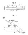
- the rotation frequency of the pulse motor under the Stationary State must be set within the range where the performance can follow-up the driving frequency of pulse motor, that is, within the range of auto-start up frequency to meet the torque necessary for performing the said scanning.
- it is necessary to provide sufficient torque margin taking into account the variation of load due to change of environmental temperature and decrease of torque of the motor itself. Therefore as illustrated in Fig.
- the driving frequency of pulse motor is N/T (pps) and when driving load is t1(Kg ⁇ cm) and pull-in torque for driving frequency N/T (pps) is t2 (Kg ⁇ cm), the motor start up torque t s (Kg ⁇ cm) is so set as to satisfy t1 ⁇ t s ⁇ t2 and t s - t1 under such state becomes the torque margin Mt.
- This torque margin Mt should theoretically be smaller at Stationary State than at start up time but it is in reality by far larger at the Stationary State than at start-up time.
- the present invention was accomplished in view of the aforementioned facts and provides the image reading apparatus which can read original image in preferred manner.
- the present invention provides the image reading apparatus wherein reading of the image is performed without disturbance even when performance is interrupted during reading of the original image.
- the present invention provides the image reading apparatus wherein the reading performance can be resumed in preferred manner even when interruption of reading occurs during reading of the original image.
- the present invention provides the image reading apparatus wherein reading performance can be stopped in preferred manner even when interruption occurs during reading of the original image.
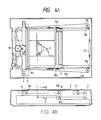
- Figures 4A and 48 illustrate the outline of the composition of the image reading apparatus of the first illustrative embodiment of the present invention.
- 1 is the read sensor wherein plural number of light receiving devices such as CCD used for reader means are arranged on a straight line, the said sensor being installed in the main body 2.
- the original placing glass 3 At the upper surface of main body 2 is provided the original placing glass 3 so that the original P placed on the original placing glass 3 is exposed and scanned by the exposure scanning mechanism and the image is formed on the said read sensor 1.
- the said exposure scanning mechanism is composed of a wire-driven lamp unit 5, mirror unit 6 and lens 7.
- Lamp unit 6 is equipped with an illumination lamp L comprising, for example, a rod-shaped halogen lamp, which illuminates the original P and the 1st mirror M1 which reflects the light of the image coming from the surface of the original irradiated by illumination lamp L toward the mirror unit 6.
- Mirror unit 6 is provided with the 2nd and 3rd mirrors M2 and M3 which reflex the light of the image reflected by the 1st mirror M1 toward the read sensor 1.
- Lamp unit 5 and mirror unit 6 are supported by a pair of rails 8a and 8b so that scanning can be done in parallel to the light axis while holding the position right angle to the light axis of the aforementioned lens 7.
- pulse motor 9 is a pulse motor which is the driving source to move lamp unit 5 and mirror unit 6 for scanning in the auxiliary scanning direction Q which is perpendicular to the main scanning direction of read sensor 1, the rotary force of the said driving source being transmitted to driving drum 10 via a line of gears.
- pulse motor is frequently used as the driving source because it facilitates position control and speed control.
- Two wires 11a and 11b being connected at one point are winded around the driving drum 10.
- mirror unit 6 scans at the speed half of the scanning speed of lamp unit 5 according to the principle of dynamic pulley, consequently the length of light path from the surface of the original to lens 7 being held always constant for the entire scanning region.
- the said lamp unit 5 and mirror unit 6 are normally set on the home position near the starting point of original reading by the home position sensor not indicated in the Figure.
- motor driving pulse synchronizing to the read synchro-signal is given to pulse motor 9 and pulse motor 9 rotates to initiate the scanning of exposure scanning mechanism in the direction of auxiliary scanning direction Q and the read image data are transmitted to the host computer.
- Host computer processes the received image data. But if the host computer is in the Busy state or its buffer which temporarily stores the received data is full, and thus impossible to process the image data, the host computer gives the reading interruption command to the reading apparatus.
- reading apparatus receives such command signal, it stops the rotation of motor 9 and stops the travelling scanning of exposure scanning mechanism, stops transmission of image data signal to host computer and takes stand-by state.
- the buffer becomes empty or conditions otherwise permit, reading resumption command is given by the host computer and reading is resumed from such point.
- FIG. 5 is an example of block diagram for processing of image data read by the image reading apparatus.
- Analogue image signal coming from read sensor 21 driven by the driving signal given by the sensor driving circuit 20 is amplified by the amplifier 22, converted into digital image signal and input into image processing circuit 24.
- the digital image signal is converted into binary signal in accordance with the instruction given by CPU27.
- CPU27 supplies the threshold value for conversion into binary signal and the data for shading compensation to the image processing circuit, using the image processing parameter stored in ROM28.
- CPU27 According to the reading interruption/resumption command given by the host computer, CPU27 also outputs the driving pulse formed by the internal timer to the motor driving circuit 29 which drives pulse motor 9 based on the driving signal given by the sensor driving circuit 20.
- the output of image processing circuit 24 is divided into two parts and one part is connected via buffer memory 25 to the second stage selector 26 which performs selection according to the instruction of CPU27 while the other part being connected to the selector 26 directly.
- Image sensor such as CCD usually functions according to the clock signals emitted at certain interval.
- To process one line of image data requires two cycles (2T) and as illustrated in Figure 6, in the first cycle, image reading (electric charge accumulation by photoelectric conversion) is executed and in the following cycle, read data is transmitted.
- selector 26 is directly connected to image processing circuit 24 and in the succeeding reading cycle, transfer of data A, B and C to the host computer is executed.
- CPU27 stops the output of driving pulse to the motor drive circuit 29.
- the data D of the line being read by reading sensor 21 is not accepted by the host computer in the following cycle but it is transferred to the host computer after resumption of reading. Consequently at the time of resumption of reading, selector 27 is connected to buffer memory 25 by CPU27 and the image data D in the last line having been read prior to the interruption is first transferred from buffer memory 25 to host computer and then selector 26 is changed over by CPU27 to return to the normal state.
- the output may be such that the images before and after stop/start SP are not properly connected as illustrated in Figure 7B.
- One of the causes for such trouble is the vibration of exposure scanning means due to abrupt stop/start but even after the influence of such vibration is eliminated, disturbance of image still remains as illustrated in the Figure 7B.
- H sync is the reading synchrosignal emitted by sensor driving circuit 20 at every storage time T(m sec) of the image sensor and SPM is the pulse motor driving signal sent from CPU27 to motor driving circuit 29 in synchronizm with the signal H sync.
- a line of data are transferred by giving 4 pulses to pulse motor 9 during T time which is a time interval between H sync outputs.
- Solid line (b) in the Figure 6 indicates that at the start after interruption, there exists a large time lag t1 after the start of rotation of pulse motor 9 until the start of motion of exposure scanning mechanism. It is due to the delay of follow up of exposure scanning mechanism from the driving pulse of pulse motor 9.
- Figure 8 indicates the performance sequence for elimination of the disturbance of image due to time lag t1.
- CPU27 After the receipt of reading resumption command from host computer, CPU27 emits, immediately after the start, driving pulse SPM for driving pulse motor 9 to the motor driving circuit 27 earlier than the emission of synchro-signal H sync for reading of the 1st line by the length of said time lag t1.
- This timing is achieved if the driving pulse is emitted at T-t1 time after the input of synchro-signal H sync immediately after the receipt of reading resumption command. If it is done so, the exposure scanning mechanism starts to rotate simultaneously with the reading synchro-signal H sync.
- motor driving pulse SPM is emitted in synchronizm with synchro-signal H sync, and consequently, during the time span of said time lag plus the time for reading of the 1st line, i.e., during (t1 + T) (m sec), it gives 4 pulses to send one line and from the 2nd line on, driving pulse synchronizing with the synchro-signal H sync is given as usual.
- the space between 4 pulses for the 1st line may be one-quarter of (t1 + T) or may be distributed otherwise in such a manner that the sum of intervals between 4 pulses becomes (t1 + T) as shown in the bracket in the Figure 8.
- the pulse number required for transmitting one line is 4 but the present invention may be practised in similar manner irrespective of such pulse number.
- the means to transmit driving force is gear and wire and the means of exposure scanning is 1:1/2 optical system, but the present invention is not limited thereto.
- the invention may be applied to the systems wherein driving force transmitting means is timing pulley and belt or exposure scanning mechanism is a one-unit type mechanism in which mirror, lens and image sensor are assembled or the composition wherein the positions of mirror, lens, image sensor are fixed and original table glass 3 is shifted by pulse motor.
- a buffer memory 25 is provided as illustrated in Figure 5 but the workable construction is not limited thereto but performance is similarly possible with such composition wherein for example a memory comprising Ram etc. which can store the data of plural number of lines is provided and the system is so controlled that the reading start position of the memory in stationary mode is different from that at the resumption of reading.
- Vibration of exposure scanning mechanism and elongation and contraction of wire depend largely on the driving method of pulse motor. That is, motor torque and vibration of motor change substantially according to the setting of pulse rate and current rating and such change influences the exposure scanning means and the wire.
- Figure 9 shows the results of measurement of vibration of exposure scanning mechanism under different lead time t2. It is evident therefrom that the vibration of exposure scanning mechanism depends on t2. Therefore it should be possible to further improve the picture quality by setting t2 at such level that time lag is offset and yet vibration becomes minimum.
- Figure 10 shows an example of constant voltage driving circuit 29 for driving pulse motor, wherein transistor tr in the Figure may be turned OFF by setting the hold signal HOLD at a high level and the current running through the coil of pulse motor 9 may be reduced by impressing DC voltage on pulse motor 9 via resistor R.
- the frequency of pulse supplied to pulse motor 9 at the start is small and therefore starting torque may be smaller than the torque during stationary run but to the contrary in the constant voltage driving, as shown in (a) of Figure 11 the current running through pulse motor 9 increases for the amount equivalent to the extention of pulse interval at point A of Figure 10.
- Such excessive torque becomes the cause of vibration of exposure scanning mechanism. Consequently it is possible to suppress such vibration at the start by reducing the current supplied to pulse motor 9 using the said HOLD circuit shown in (b) of Figure 11.
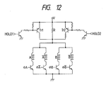
- the system may be so constructed that the number of bypass is increased and the circuits used at starting time and those used at holding time may be separated so that at the stop, hold signals HOLD 1 and HOLD 2 are set at a high level and transistors tr1 and tr2 are both turned OFF whereas at the start, only hold signal HOLD 1 is set at a high level and transistor tr1 and tr2 are set at OFF, ON state, thus suppressing the current to be impressed on pulse motor 9 at the stop and the start.
- time lag exists for n lines
- the influence of time lag may be reduced by distributing 4*n pulses over the time span of (t1 + n*T).
- line buffer with minimum capacity of n lines is naturally required.
- the pulse motor drive control at the time of resumption of reading after interruption has been explained but as stated above, disturbance of image occurs not only at the resumption of reading but also at the stop for interruption due to the vibration of exposure scanning mechanism.
- Hold time it is necessary to run holding current through pulse motor 9 to keep it in stopped state (hereinafter called Hold time), but the rating of such current may be smaller than that at the start up and therefore the motor driving circuit 29 is usually provided with the circuit which enables to change over the current rating given to pulse motor 9 in two steps, namely, the rating for the stopped state and that for stationary state, for example, as illustrated in Figure 14.
- hold signal HOLD given to transistor Tr is set at High to turn ON the transistor Tr and impress DC voltage directly on the pulse motor 9.
- hold signal HOLD may be set at low, transistor Tr may be turned OFF and DC current may be impressed on pulse motor 9 via resistor R for reading the lines M + 1 and on, so that the current running through the coil of pulse motor 9 is reduced and consequently the torque of pulse motor 9 may be reduced pro rata thereto.
- the resistor R is so set that the pulse motor 9 is given the current rating which provides the torque with sufficient margin over the torque necessary for pulse motor 9 at stationary state. While the reading is suspended upon receipt of the data output stop signal from the host computer, the hold signal HOLD is kept Low after the aforementioned change-over of current.
- the current rating given to pulse motor 9 in the stationary state is identical to the current rating at Hold time, which is smaller than the current running at start up and thus excessive torque is reduced and consequently vibration of exposure scanning mechanism at the stop is reduced. Since the circuit of conventional apparatus may be used as it is, the practise of this invention accompanies no additional expenditure.
- the circuit used in this Illustrative Embodiment is so constructed that additional transistors and resistors are provided to the circuit of Illustrative Embodiment 5 so that the current rating given to pulse motor 9 may be changed over in 3 modes, namely, start up mode, stationary mode and Hold mode and thus the Hold current in this Illustrative Embodiment is set further smaller than the current rating at stationary mode and consequently vibration and unnecessary temperature increase within the main body of equipment 2 at Hold state are reduced to the level less than those in the
- Ram 30 which can store M lines of image data whenever the pulse motor 9 reaches stationary state within the time for scanning M lines (M ⁇ 1) by the reading means and such Ram 30 is controlled by CPU27.
- the image signal read by read sensor 21 is entered into Ram 30 via image processing circuit 24 and sent to the host computer in the succeeding cycle wherein the order of processing is predetermined so that the data of the 1st line after the start or resumption of reading are entered into the 1st area of the Ram and the data of the 2nd line into the 2nd area of Ram and so on, thus the minimum unit from the data output demand signal up to the data output stop signal given by host computer being one line.
- the lines to be read after resumption of reading are numbered (1), (2), (3) and on and the lines having been read prior thereto are numbered progressively backward as (0), (-1), (-2) and on. If data output stop signal is received during rcading of line (0), it is during the time when the data of line (-2) in Ram 30 (the data in area P-1 in the Figure) are being transferred to host computer and the data of line (-1) are being entered into area P of Ram 30. In the following cycle, the data of line (0) are entered into area M + 1 of Ram 30.
- a picture reading equipment has a reader for reading image of an original, moving unit for moving an image reading position of said reader, and a driver for supplying a driving signal to said moving unit.
- the timing of feed of the driving signal is so controlled that vibration of said driver and a scanning system is reduced and a picture of high quality is obtained even when interruption/resumption of reading is made during reading of an image.
Abstract
Description
- The present invention relates to an image reading apparatus for reading an image on the original.
- The applicant of the present invention proposed the image reading apparatus used for digital copying machine, image reader and facsimile etc. in the US Application No. 139,116 (cont.), US Application No. 917,549, US Patent No. 4663672 etc. Some of these apparatus employ the so-called optical system which scans the original placed on the glass of the original table by light source and a mirror and forms its image on the read sensor. As illustrated in Fig. 11 the said optical system illuminates the original P placed on the
fixed glass 100 of the original table by a rod-shaped light source 101, reflects upon necessity the light of the image, which is the reflection of original P, bymirrors read sensor 106 such as one-dimensional CCD image sensor, through theimage forming lens 105. - In this case, the length of light path extending from the surface of the original to the
image forming lens 105 is always kept constant by setting the scanning speed ofmirror light source 101 andmirror 102. - Among this kind of image reading apparatus, there are some which require repeated interruption/resumption of reading whenever necessary during reading of one page of the original for convenience of the recipient of data. For example, in the case of the image scanner for computer input, when the buffer of the host computer for temporary storage of received data becomes full, the temporary reading by the image scanner is suspended and reading is resumed when the data processing by host computer is completed and input becomes possible.
- That is, the image scanner shown in Fig. 1 sends the image data to the host computer upon receipt of data output demand signal from the host computer (not indicated in the Figure) and the host computer once stores the delivered image data in the buffer memory and processes the image by taking out the image data stored in the buffer memory one after another. Here, if the said buffer memory becomes full of image data (hereinafter called Buffer Full State) while the said host computer is processing the image (hereinafter called Busy state), the host computer sends the data output stop signal to the said image scanner to avoid overflow of delivered data and thereby suspends the temporary reading performance. When the said host computer is liberated from Busy state and buffer memory becomes empty of image data (hereinafter called Buffer Empty), the host computer sends the data output demand signal to the image scanner and the image scanner resumes reading.
- When such interruption/resumption is done during reading of one page of the original, such problem may occur that the images before and after the point of interruption of reading do not properly meet each other and the picture quality deteriorates.
- Generally speaking, the read sensor such as CCD image sensor is driven by the pulses of fixed interval, from the necessity to keep the reading output uniform. On the other hand, in order to ensure smooth start/stop of the pulse motor which causes light source, mirror etc. to scan, it is indispensable to have a slow up/slow down control. Therefore in order to properly meet the images before and after interruption/resumption of reading, it is necessary to simultaneously satisfy the aforementioned two requirements which are fundamentally contradictory with each other.
- To solve this problem, with the conventional image reading apparatus, the exposure scanning system is caused to retreat by n lines after interruption if n lines are necessary for slow up and when the system is resumed, slow up is made during such n line delay and image reading is begun from the (n+1)th line, thus properly meeting the image to the image before the interruption but such arrangement causes substantial delay of processing speed.
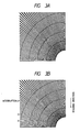
- In a case where the pulse motor must be started and stopped by the specified driving frequency pluse in the state where scanning is being done under stationary conditions (hereinafter called Stationary State), the rotation frequency of the pulse motor under the Stationary State must be set within the range where the performance can follow-up the driving frequency of pulse motor, that is, within the range of auto-start up frequency to meet the torque necessary for performing the said scanning. In addition, it is necessary to provide sufficient torque margin taking into account the variation of load due to change of environmental temperature and decrease of torque of the motor itself. Therefore as illustrated in Fig. 2, when the number of pulses required for forwarding the motor by 1 line is N and the cycle of reading interval of CCD image sensor is T, the driving frequency of pulse motor is N/T (pps) and when driving load is t₁(Kg·cm) and pull-in torque for driving frequency N/T (pps) is t₂ (Kg·cm), the motor start up torque ts(Kg·cm) is so set as to satisfy t₁ < ts < t₂ and ts - t₁ under such state becomes the torque margin Mt. This torque margin Mt should theoretically be smaller at Stationary State than at start up time but it is in reality by far larger at the Stationary State than at start-up time. Excessive torque becomes the cause of vibration of motor itself or scanning system and in particular at the time of stopping, it falls into the state as if an emergency brake has been engaged and as the result clattering of motor itself and scanning system due to vibration becomes substantial. In other words, when interruption/resumption performance is made during reading, image output of the original as shown in Fig. 3A becomes as shown in Fig. 38 and the images before and after the point of interruption/resumption do not connect properly due to the aforesaid vibration and thus picture quality deteriorates.
- The present invention was accomplished in view of the aforementioned facts and provides the image reading apparatus which can read original image in preferred manner.
- In still another aspect, the present invention provides the image reading apparatus wherein reading of the image is performed without disturbance even when performance is interrupted during reading of the original image.
- In still another aspect, the present invention provides the image reading apparatus wherein the reading performance can be resumed in preferred manner even when interruption of reading occurs during reading of the original image.
- In still another aspect, the present invention provides the image reading apparatus wherein reading performance can be stopped in preferred manner even when interruption occurs during reading of the original image.
- The aforementioned objective and effect of the present invention and other objectives and effects would be evident from the following explanation.
-
- Figure 1 is a schematic view to illustrate the example of composition of image reading apparatus (image scanner) of the present invention.
- Figure 2 shows a frequency-torque characteristic curve of pulse motor.
- Figure 3A is a view illustrating an original wherein a radial lines are drawn.
- Figure 3B is a view illustrating an example of output obtained by reading the original of the said Figure 3(a) by the scanner of a conventional apparatus.
- Figures 4A and 4B show a schematic view of the construction of the image reading apparatus which practises the present invention.
- Figure 5 and Figure 17 are the block diagrams of the image reading apparatus which practises the present invention.
- Figure 6 is a timing chart indicating the image reading performance.
- Figures 7A and 7B show a view illustrating an example of image having been read and the reproduced image.
- Figures 8, 11, 13, 15 and 18 are the timing charts illustrating the performance of the image reading apparatus which practises the present invention.
- Figure 9 is a view illustrating the state of vibration of exposure scanning mechanism.
- Figures 10, 12, 14 and 16 are the driving circuit diagrams of pulse motor.
- Hereunder is explained the first illustrative embodiment wherein the present invention is applied.
- Figures 4A and 48 illustrate the outline of the composition of the image reading apparatus of the first illustrative embodiment of the present invention. In the Figure, 1 is the read sensor wherein plural number of light receiving devices such as CCD used for reader means are arranged on a straight line, the said sensor being installed in the
main body 2. At the upper surface ofmain body 2 is provided the original placingglass 3 so that the original P placed on the original placingglass 3 is exposed and scanned by the exposure scanning mechanism and the image is formed on the saidread sensor 1. - The said exposure scanning mechanism is composed of a wire-driven
lamp unit 5,mirror unit 6 andlens 7.Lamp unit 6 is equipped with an illumination lamp L comprising, for example, a rod-shaped halogen lamp, which illuminates the original P and the 1st mirror M1 which reflects the light of the image coming from the surface of the original irradiated by illumination lamp L toward themirror unit 6.Mirror unit 6 is provided with the 2nd and 3rd mirrors M2 and M3 which reflex the light of the image reflected by the 1st mirror M1 toward theread sensor 1. -
Lamp unit 5 andmirror unit 6 are supported by a pair ofrails aforementioned lens 7. - 9 is a pulse motor which is the driving source to move
lamp unit 5 andmirror unit 6 for scanning in the auxiliary scanning direction Q which is perpendicular to the main scanning direction ofread sensor 1, the rotary force of the said driving source being transmitted to drivingdrum 10 via a line of gears. Generally speaking, for this sort of image reading apparatus, pulse motor is frequently used as the driving source because it facilitates position control and speed control. Twowires driving drum 10. One end of each wire fixed tolamp unit 5 at certain point, semi-circles around the outer circumferences ofpulleys mirror unit 6 and are fixed to the main body. The other ends ofwires pulleys tension spring 13. In this way,mirror unit 6 scans at the speed half of the scanning speed oflamp unit 5 according to the principle of dynamic pulley, consequently the length of light path from the surface of the original tolens 7 being held always constant for the entire scanning region. - The said
lamp unit 5 andmirror unit 6 are normally set on the home position near the starting point of original reading by the home position sensor not indicated in the Figure. When reading start order is received from the host computer connected to the said reading apparatus, motor driving pulse synchronizing to the read synchro-signal is given topulse motor 9 andpulse motor 9 rotates to initiate the scanning of exposure scanning mechanism in the direction of auxiliary scanning direction Q and the read image data are transmitted to the host computer. - Host computer processes the received image data. But if the host computer is in the Busy state or its buffer which temporarily stores the received data is full, and thus impossible to process the image data, the host computer gives the reading interruption command to the reading apparatus. When reading apparatus receives such command signal, it stops the rotation of
motor 9 and stops the travelling scanning of exposure scanning mechanism, stops transmission of image data signal to host computer and takes stand-by state. When the buffer becomes empty or conditions otherwise permit, reading resumption command is given by the host computer and reading is resumed from such point. - Figure 5 is an example of block diagram for processing of image data read by the image reading apparatus. Analogue image signal coming from
read sensor 21 driven by the driving signal given by thesensor driving circuit 20 is amplified by theamplifier 22, converted into digital image signal and input intoimage processing circuit 24. At theimage processing circuit 24, the digital image signal is converted into binary signal in accordance with the instruction given by CPU27. CPU27 supplies the threshold value for conversion into binary signal and the data for shading compensation to the image processing circuit, using the image processing parameter stored in ROM28. According to the reading interruption/resumption command given by the host computer, CPU27 also outputs the driving pulse formed by the internal timer to themotor driving circuit 29 which drivespulse motor 9 based on the driving signal given by thesensor driving circuit 20. The output ofimage processing circuit 24 is divided into two parts and one part is connected viabuffer memory 25 to thesecond stage selector 26 which performs selection according to the instruction of CPU27 while the other part being connected to theselector 26 directly. - Image sensor such as CCD usually functions according to the clock signals emitted at certain interval. To process one line of image data requires two cycles (2T) and as illustrated in Figure 6, in the first cycle, image reading (electric charge accumulation by photoelectric conversion) is executed and in the following cycle, read data is transmitted.
- Usually,
selector 26 is directly connected toimage processing circuit 24 and in the succeeding reading cycle, transfer of data A, B and C to the host computer is executed. However, at the time when host computer emits the reading interruption command, CPU27 stops the output of driving pulse to themotor drive circuit 29. At the same time, the data D of the line being read by readingsensor 21 is not accepted by the host computer in the following cycle but it is transferred to the host computer after resumption of reading. Consequently at the time of resumption of reading,selector 27 is connected to buffermemory 25 by CPU27 and the image data D in the last line having been read prior to the interruption is first transferred frombuffer memory 25 to host computer and thenselector 26 is changed over by CPU27 to return to the normal state. - Generally speaking to initiate rotation of
pulse motor 9, slow up and slow down (to gradually increase or reduce rotation frequency) are used to make a smooth shift from stopped state to stationary state or vice versa. However in the case of image sensor such as CCD, it is necessary to hold the time span for reading of each line (storage time) constant and consequently the aforementioned slow up/slow down adjustment can not be used at the interruption/resumption of reading (hereinafter abreviated as stop/start) but change over to stop/start must be done abruptly at the rotation frequency of stationary state from the beginning. In other words, when storage time per line of image sensor is T and pulse number of pulse motor required for transfer of 1 line is n, the pulse motor must abruptly stop/start at the motor driving pulse of n/T(pps) (SPM of Figure 6). - When the apparatus is instructed to sead the original as shown in Figure 7A with stop/start SP motion on the way, the output may be such that the images before and after stop/start SP are not properly connected as illustrated in Figure 7B. One of the causes for such trouble is the vibration of exposure scanning means due to abrupt stop/start but even after the influence of such vibration is eliminated, disturbance of image still remains as illustrated in the Figure 7B.
- In the investigation of the synchro-signal, motor driving pulse, motor rotation and motion of exposure scanning apparatus immediately after the start, it has been revealed that exposure scanning mechanism shifts with some delay after giving the motor driving pulse as illustrated by the solid line (b), contrary to our expectation that the motion of exposure scanning mechanism at the reading of data E should be as shown by the dotted line (a) of Figure 6.
- In the Figure 6, H sync is the reading synchrosignal emitted by
sensor driving circuit 20 at every storage time T(m sec) of the image sensor and SPM is the pulse motor driving signal sent from CPU27 tomotor driving circuit 29 in synchronizm with the signal H sync. In this example, A line of data are transferred by giving 4 pulses topulse motor 9 during T time which is a time interval between H sync outputs. Solid line (b) in the Figure 6 indicates that at the start after interruption, there exists a large time lag t1 after the start of rotation ofpulse motor 9 until the start of motion of exposure scanning mechanism. It is due to the delay of follow up of exposure scanning mechanism from the driving pulse ofpulse motor 9. - Figure 8 indicates the performance sequence for elimination of the disturbance of image due to time lag t1. After the receipt of reading resumption command from host computer, CPU27 emits, immediately after the start, driving pulse SPM for driving
pulse motor 9 to themotor driving circuit 27 earlier than the emission of synchro-signal H sync for reading of the 1st line by the length of said time lag t1. This timing is achieved if the driving pulse is emitted at T-t1 time after the input of synchro-signal H sync immediately after the receipt of reading resumption command. If it is done so, the exposure scanning mechanism starts to rotate simultaneously with the reading synchro-signal H sync. As stated above, in principle, motor driving pulse SPM is emitted in synchronizm with synchro-signal H sync, and consequently, during the time span of said time lag plus the time for reading of the 1st line, i.e., during (t1 + T) (m sec), it gives 4 pulses to send one line and from the 2nd line on, driving pulse synchronizing with the synchro-signal H sync is given as usual. - The space between 4 pulses for the 1st line may be one-quarter of (t1 + T) or may be distributed otherwise in such a manner that the sum of intervals between 4 pulses becomes (t1 + T) as shown in the bracket in the Figure 8.
- By performing the control as shown in Figure 8, the exposure scanning system perfectly follows up the synchro-signal H sync at the time of reading of data E. Therefore the images are connected smoothly even when stop/start motion is made on the way and no image disturbance at the seam mark as shown in Figure 7B appears.
- Even when the aforementioned control is effected at the start of reading of the front end of the original, the image is not at all degradated and therefore it is unnecessary to change the control method by the judgement as to whether it is at the start of reading or at the resumption of reading after interruption.
- In the aforementioned example the pulse number required for transmitting one line is 4 but the present invention may be practised in similar manner irrespective of such pulse number. Explanation was made on the example wherein the means to transmit driving force is gear and wire and the means of exposure scanning is 1:1/2 optical system, but the present invention is not limited thereto. For example, the invention may be applied to the systems wherein driving force transmitting means is timing pulley and belt or exposure scanning mechanism is a one-unit type mechanism in which mirror, lens and image sensor are assembled or the composition wherein the positions of mirror, lens, image sensor are fixed and
original table glass 3 is shifted by pulse motor. In order to transfer the data of the line being read immediately before interruption to the host computer at the resumption of reading, abuffer memory 25 is provided as illustrated in Figure 5 but the workable construction is not limited thereto but performance is similarly possible with such composition wherein for example a memory comprising Ram etc. which can store the data of plural number of lines is provided and the system is so controlled that the reading start position of the memory in stationary mode is different from that at the resumption of reading. - Vibration of exposure scanning mechanism and elongation and contraction of wire depend largely on the driving method of pulse motor. That is, motor torque and vibration of motor change substantially according to the setting of pulse rate and current rating and such change influences the exposure scanning means and the wire.
- In the aforementioned example, explanation was made on the method wherein exposure scanning mechanism is moved earlier than other systems by the length equivalent to the time lag t1 of the exposure scanning means behind the read synchro-signal, but it is unnecessary to accurately match the lead time of the motion of exposure scanning mechanism against the synchro-signal H sync to t1. In other words, the lead time t2 of pulse impression start against read synchro-signal H sync may be set at t2 = t1 + dt(-t1 < dt) which is in the range where there should be no influence of time lag on the image.
- Figure 9 shows the results of measurement of vibration of exposure scanning mechanism under different lead time t2. It is evident therefrom that the vibration of exposure scanning mechanism depends on t2. Therefore it should be possible to further improve the picture quality by setting t2 at such level that time lag is offset and yet vibration becomes minimum.
- When image reading apparatus is at stand-by position or it is stopped by interruption order from host computer during reading, hold current is running through the
pulse motor 9 to hold it at the stopped position. - Figure 10 shows an example of constant
voltage driving circuit 29 for driving pulse motor, wherein transistor tr in the Figure may be turned OFF by setting the hold signal HOLD at a high level and the current running through the coil ofpulse motor 9 may be reduced by impressing DC voltage onpulse motor 9 via resistor R. - In the example shown in Figure 8, the frequency of pulse supplied to
pulse motor 9 at the start is small and therefore starting torque may be smaller than the torque during stationary run but to the contrary in the constant voltage driving, as shown in (a) of Figure 11 the current running throughpulse motor 9 increases for the amount equivalent to the extention of pulse interval at point Ⓐ of Figure 10. Such excessive torque becomes the cause of vibration of exposure scanning mechanism. Consequently it is possible to suppress such vibration at the start by reducing the current supplied topulse motor 9 using the said HOLD circuit shown in (b) of Figure 11. - The foregoing paragraphs introduce the method to suppress vibration without changing the existing circuit but as illustrated in Figure 12, the system may be so constructed that the number of bypass is increased and the circuits used at starting time and those used at holding time may be separated so that at the stop, hold
signals HOLD 1 andHOLD 2 are set at a high level and transistors tr1 and tr2 are both turned OFF whereas at the start, only holdsignal HOLD 1 is set at a high level and transistor tr1 and tr2 are set at OFF, ON state, thus suppressing the current to be impressed onpulse motor 9 at the stop and the start. - In the [Illustrative Embodiment 1], it was assumed that from the 2nd line after the resumption of reading, the exposure scanning means can follow up the read synchro-signal, but depending on the weight of the exposure scanning mechanism etc., time lag may still exist even at the 2nd line for reading data F as shown in (a) of Figure 13.
- In such case, during the initial time lag plus the time for reading two lines, i.e., (t1 + 2T), driving pulses for 2 lines, namely, 8 pulses may be given. But in this case, once reading starts, it must read at least 2 lines and therefore buffer
memory 25 for image disposal in Figure 5 requires the minimum capacity of 2 lines data. - Likewise if time lag exists for n lines, the influence of time lag may be reduced by distributing 4*n pulses over the time span of (t1 + n*T). In this case, line buffer with minimum capacity of n lines is naturally required.
- In this illustrative embodiment, the method introduced in [Illustrative Embodiment 2] or [Illustrative Embodiment 3] may be employed.
- As explained above, with the image reading apparatus of the present invention, even when Stop/Start action is entered on the way of reading original, a smooth image as good as the one obtained by continuous reading can be obtained.
- In practising the above construction, there is another significant advantage, that is, it accompanies no additional expenditure.
- To give driving pulse to the motor prior to the read synchro-signal means essentially a slow up operation and it has the concurrent effect to reduce vibration of to the exposure scanning mechanism due to shock at the start. Through the multiplication effect of these elements, a substantial improvement of the quality of read image is obtained.
- In the illustrative embodiments given above, the pulse motor drive control at the time of resumption of reading after interruption has been explained but as stated above, disturbance of image occurs not only at the resumption of reading but also at the stop for interruption due to the vibration of exposure scanning mechanism.
- In the
illustrative embodiment 5, explanation shall be made on the prevention of vibration of exposure scanning mechanism at the stop. - As stated above, it is necessary to run holding current through
pulse motor 9 to keep it in stopped state (hereinafter called Hold time), but the rating of such current may be smaller than that at the start up and therefore themotor driving circuit 29 is usually provided with the circuit which enables to change over the current rating given topulse motor 9 in two steps, namely, the rating for the stopped state and that for stationary state, for example, as illustrated in Figure 14. Using the above circuit, at the time of start or resumption of reading, hold signalHOLD given to transistor Tr is set at High to turn ON the transistor Tr and impress DC voltage directly on thepulse motor 9. As illustrated in Figure 15, when rotation ofpulse motor 9 reaches the stationary state after the time for scanning M lines (M ≧ 1) after start or resumption of reading, hold signalHOLD may be set at low, transistor Tr may be turned OFF and DC current may be impressed onpulse motor 9 via resistor R for reading the lines M + 1 and on, so that the current running through the coil ofpulse motor 9 is reduced and consequently the torque ofpulse motor 9 may be reduced pro rata thereto. Here the resistor R is so set that thepulse motor 9 is given the current rating which provides the torque with sufficient margin over the torque necessary forpulse motor 9 at stationary state. While the reading is suspended upon receipt of the data output stop signal from the host computer, the hold signalHOLD is kept Low after the aforementioned change-over of current. Therefore the current rating given topulse motor 9 in the stationary state is identical to the current rating at Hold time, which is smaller than the current running at start up and thus excessive torque is reduced and consequently vibration of exposure scanning mechanism at the stop is reduced. Since the circuit of conventional apparatus may be used as it is, the practise of this invention accompanies no additional expenditure. - Next the
Illustrative Embodiment 6 of the present invention is explained in reference to Figure 16. - The same expressions as those used in the aforementioned
illustrative embodiment 1 are given the same symbol. The circuit used in this Illustrative Embodiment is so constructed that additional transistors and resistors are provided to the circuit ofIllustrative Embodiment 5 so that the current rating given topulse motor 9 may be changed over in 3 modes, namely, start up mode, stationary mode and Hold mode and thus the Hold current in this Illustrative Embodiment is set further smaller than the current rating at stationary mode and consequently vibration and unnecessary temperature increase within the main body ofequipment 2 at Hold state are reduced to the level less than those in the - Explanation of other constructions and performances are omitted as they are same with those of
Illustrative Embodiment 5. - Next the
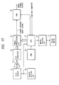
Illustrative Embodiment 7 of the present invention is illustrated in Figures 17 and 18 and the construction of its control is explained in reference to Figure 17. For the same expression with those ofIllustrative Embodiment 1, the same symbol shall be used. - CPU27 in this Illustrative Embodiment is provided with
Ram 30 which can store M lines of image data whenever thepulse motor 9 reaches stationary state within the time for scanning M lines (M ≧ 1) by the reading means andsuch Ram 30 is controlled by CPU27. In the following cycle, the image signal read byread sensor 21 is entered intoRam 30 viaimage processing circuit 24 and sent to the host computer in the succeeding cycle wherein the order of processing is predetermined so that the data of the 1st line after the start or resumption of reading are entered into the 1st area of the Ram and the data of the 2nd line into the 2nd area of Ram and so on, thus the minimum unit from the data output demand signal up to the data output stop signal given by host computer being one line. - Next the example of performance of this Illustrative Embodiment is explained in reference to Figure 18.
- First, the lines to be read after resumption of reading are numbered (1), (2), (3) and on and the lines having been read prior thereto are numbered progressively backward as (0), (-1), (-2) and on. If data output stop signal is received during rcading of line (0), it is during the time when the data of line (-2) in Ram 30 (the data in area P-1 in the Figure) are being transferred to host computer and the data of line (-1) are being entered into area P of
Ram 30. In the following cycle, the data of line (0) are entered into area M + 1 ofRam 30. After resumption of reading, when host computer gives data output stop signal again, the exposure scanning mechanism does not stop immediately but as stated above, it continues to scan for the number of lines (M + 1) necessary for stable operation. Thus to the host computer are transferred only the data in area P. The data of lines (1), (2), (3) and on which have been read after the receipt of data output stop signal are entered intoarea Ram 30 one after another but the data of line (M + 1) are entered into area M + 1 because the data of area M + 1 [data of line (0)] have not been transferred yet. When reading is resumed next, exposure scanning mechanism does not start scanning immediately but first the data ofRam 30 are transferred in the order of area M + 1, 1, 2 ....... M - 1, M, M + 2 and simultaneously with the start of transfer of data in area M, exposure scanning mechanism resumes scanning and entry of image data intoRam 30 begins. That is, while the exposure scanning mechanism is continuously scanning, entry intoRam 30 is repeatedly made by the order of 1, 2 ..... M, 1, 2 ..... and the data read at the receipt of data output stop signal are entered interchangeably into M + 1 or M + 2. - Therefore in this illustrative Embodiment, even when the data output stop signal is received from host computer before the exposure scanning mechanism reaches stationary state, scanning does not stop immediately but it stops when the torque of pulse motor becomes small so that the vibration of exposure scanning mechanism at the stop is suppressed.
- Explanation of other constructions and performances is omitted as they are the same as those described in
Illustrative Embodiment 1. - In the aforementioned Illustrative Embodiments 5 - 7, explanation was made by assuming that the pulse number required for transfer of 1 line is 4 but the present invention may be practised irrespective of pulse number.
- Explanation was also made on the example wherein gear and wire are used as driving force transmitting means and 1:1/2 optical system is used for optical scanning means but the present invention is not limited thereto and applicable for example also to such mechanism that timing pulley and belt are used for driving transmission means and a one unit type optical scanning means incorporating mirror, lens and sensor in one unit is used.
- As explained above in the present invention unnecessary torque of driving means is reduced, vibration of the said driving means and the scanning system is suppressed and the system can be stopped without vibration even when interruption/resumption order is entered during reading of image and thus smooth picture with quality as good as that obtained by continuous reading can be obtained.
- Besides, since no additional time is required for reading, the speed of reading does not decrease.
- While the present invention has been explained in reference to a few preferred illustrative embodiments, it should be understood of course that the present invention is not limited to the composition of the said illustrative embodiments since many deformations and modifications are possible within the scope of the claim.
- A picture reading equipment has a reader for reading image of an original, moving unit for moving an image reading position of said reader, and a driver for supplying a driving signal to said moving unit. The timing of feed of the driving signal is so controlled that vibration of said driver and a scanning system is reduced and a picture of high quality is obtained even when interruption/resumption of reading is made during reading of an image.
Claims (16)
reading means for reading image of an original line by line, said reading means repeating the reading action at a predetermined cycle;
moving means for moving an image reading position of said reading means; and
driving means for supplying a driving signal to said moving means,
wherein the said driving means supplies the driving signal to said moving means prior to the read action of said reading means during reading of the image at nth line (n is an integral number larger than 1) after the start of image reading and supplies the driving signal to said moving means in synchronizm with the read action of said reading means during reading of the image of (n + 1)th line and on.
reading means for reading image of an original line by line;
moving means for moving an image reading position of said reading means; and
driving means for supplying a driving signal to said moving means,
wherein the driving force of said driving means is made large during the reading of the image at nth line (n is an integral number larger than 1) and made small during reading of the image of (n + 1)th line and on.
reading means for reading image of an original line by line;
moving means for moving an image reading position of said reading means; and
driving means for supplying a driving signal to said moving means,
wherein the driving signal is fed to said moving means to shift an image reading position of said reading means by preset lines by said moving means even when the image reading interruption instruction is given.
Applications Claiming Priority (4)
| Application Number | Priority Date | Filing Date | Title |
|---|---|---|---|
| JP258556/88 | 1988-10-14 | ||
| JP63258556A JP3015035B2 (en) | 1988-10-14 | 1988-10-14 | Image reading device |
| JP19547/89 | 1989-01-31 | ||
| JP1019547A JPH02202167A (en) | 1989-01-31 | 1989-01-31 | Image exposing device |
Publications (3)
| Publication Number | Publication Date |
|---|---|
| EP0363983A2 true EP0363983A2 (en) | 1990-04-18 |
| EP0363983A3 EP0363983A3 (en) | 1990-12-12 |
| EP0363983B1 EP0363983B1 (en) | 1994-09-14 |
Family
ID=26356390
Family Applications (1)
| Application Number | Title | Priority Date | Filing Date |
|---|---|---|---|
| EP89119072A Expired - Lifetime EP0363983B1 (en) | 1988-10-14 | 1989-10-13 | Image reading apparatus |
Country Status (3)
| Country | Link |
|---|---|
| US (1) | US5164845A (en) |
| EP (1) | EP0363983B1 (en) |
| DE (1) | DE68918212T2 (en) |
Cited By (4)
| Publication number | Priority date | Publication date | Assignee | Title |
|---|---|---|---|---|
| EP0515088A1 (en) * | 1991-05-22 | 1992-11-25 | Hewlett-Packard Company | Scanner Y-positioning accuracy control device and method |
| EP0905969A2 (en) * | 1997-09-29 | 1999-03-31 | Canon Kabushiki Kaisha | Image reading system |
| US6377362B1 (en) * | 1998-05-20 | 2002-04-23 | Mustek Systems, Inc. | Method and apparatus for obtaining magnification error for image scanning apparatus |
| CN100379244C (en) * | 2000-05-22 | 2008-04-02 | 佳能株式会社 | Image sensing apparatus and control method therefor |
Families Citing this family (9)
| Publication number | Priority date | Publication date | Assignee | Title |
|---|---|---|---|---|
| US5239393A (en) * | 1988-10-14 | 1993-08-24 | Canon Kabushiki Kaisha | Image reading apparatus |
| TW376491B (en) * | 1991-06-22 | 1999-12-11 | Fuji Xerox Co Ltd | Image processing system with a buffer memory |
| JP3183698B2 (en) * | 1992-02-28 | 2001-07-09 | 株式会社リコー | Image reading device |
| JPH09153987A (en) * | 1995-11-29 | 1997-06-10 | Murata Mach Ltd | Flat plate projection type scanning reader |
| JP3428821B2 (en) | 1996-06-17 | 2003-07-22 | キヤノン株式会社 | Image reading device |
| TW474097B (en) * | 2000-04-26 | 2002-01-21 | Umax Data Systems Inc | Method for reducing discontinuity in scanning |
| US7349132B2 (en) * | 2003-01-30 | 2008-03-25 | Kabushiki Kaisha Toshiba | Image reading apparatus |
| US7770439B2 (en) * | 2006-10-17 | 2010-08-10 | Veeco Instruments Inc. | Method and apparatus of scanning a sample using a scanning probe microscope |
| US7843611B2 (en) | 2007-07-18 | 2010-11-30 | Kuwait University | High speed flatbed scanner comprising digital image-capture module with two-dimensional optical image photo-sensor or digital camera |
Citations (3)
| Publication number | Priority date | Publication date | Assignee | Title |
|---|---|---|---|---|
| US4217611A (en) * | 1977-05-16 | 1980-08-12 | Ricoh Company, Ltd. | Optoelectronic scanning apparatus |
| JPS58170169A (en) * | 1982-03-30 | 1983-10-06 | Toshiba Corp | Picture transfer control system |
| US4843480A (en) * | 1986-09-12 | 1989-06-27 | Cannon Kabushiki Kaisha | Image reading apparatus for removing disturbances in output images |
Family Cites Families (10)
| Publication number | Priority date | Publication date | Assignee | Title |
|---|---|---|---|---|
| JPS5341920A (en) * | 1976-09-29 | 1978-04-15 | Ricoh Co Ltd | Telautograph information reading device |
| JP2501550B2 (en) * | 1983-10-06 | 1996-05-29 | キヤノン株式会社 | Image reader |
| US4712139A (en) * | 1983-10-28 | 1987-12-08 | Canon Kabushiki Kaisha | Image communication apparatus |
| JPS60103769A (en) * | 1983-11-10 | 1985-06-08 | Canon Inc | Reading method of original |
| US4992888A (en) * | 1985-10-18 | 1991-02-12 | Canon Kabushiki Kaisha | Image reading apparatus using a motor and controlling driving pulses supplied to the motor |
| EP0260892B1 (en) * | 1986-09-16 | 1993-02-03 | Matsushita Electric Industrial Co., Ltd. | Copier with accurately position-controllable sub-scanning unit |
| JPS63190595A (en) * | 1987-01-30 | 1988-08-08 | Canon Inc | Driving circuit for stepping motor |
| JPS63233663A (en) * | 1987-03-20 | 1988-09-29 | Toshiba Corp | Reader |
| JPS63245577A (en) * | 1987-03-31 | 1988-10-12 | Fujitsu Ltd | Picture input system |
| JP2693483B2 (en) * | 1988-05-17 | 1997-12-24 | キヤノン株式会社 | Sheet transport device and faximili device equipped with the same |
-
1989
- 1989-10-13 EP EP89119072A patent/EP0363983B1/en not_active Expired - Lifetime
- 1989-10-13 DE DE68918212T patent/DE68918212T2/en not_active Expired - Fee Related
-
1991
- 1991-06-27 US US07/724,466 patent/US5164845A/en not_active Expired - Lifetime
Patent Citations (3)
| Publication number | Priority date | Publication date | Assignee | Title |
|---|---|---|---|---|
| US4217611A (en) * | 1977-05-16 | 1980-08-12 | Ricoh Company, Ltd. | Optoelectronic scanning apparatus |
| JPS58170169A (en) * | 1982-03-30 | 1983-10-06 | Toshiba Corp | Picture transfer control system |
| US4843480A (en) * | 1986-09-12 | 1989-06-27 | Cannon Kabushiki Kaisha | Image reading apparatus for removing disturbances in output images |
Non-Patent Citations (1)
| Title |
|---|
| PATENT ABSTRACTS OF JAPAN, vol. 8, no. 4 (E-220)[1441], 10th January 1984; & JP-A-58 170 169 (TOKYO SHIBAURA DENKI K.K.) 06-10-1983 * |
Cited By (8)
| Publication number | Priority date | Publication date | Assignee | Title |
|---|---|---|---|---|
| US5341225A (en) * | 1991-05-14 | 1994-08-23 | Hewlett-Packard Company | Image scanning system and method with improved repositioning |
| EP0515088A1 (en) * | 1991-05-22 | 1992-11-25 | Hewlett-Packard Company | Scanner Y-positioning accuracy control device and method |
| EP0905969A2 (en) * | 1997-09-29 | 1999-03-31 | Canon Kabushiki Kaisha | Image reading system |
| EP0905969A3 (en) * | 1997-09-29 | 2001-04-25 | Canon Kabushiki Kaisha | Image reading system |
| US6747765B2 (en) | 1997-09-29 | 2004-06-08 | Canon Kabushiki Kaisha | Image reading system |
| US6377362B1 (en) * | 1998-05-20 | 2002-04-23 | Mustek Systems, Inc. | Method and apparatus for obtaining magnification error for image scanning apparatus |
| CN100379244C (en) * | 2000-05-22 | 2008-04-02 | 佳能株式会社 | Image sensing apparatus and control method therefor |
| EP1158759A3 (en) * | 2000-05-22 | 2008-06-04 | Canon Kabushiki Kaisha | Image sensing apparatus and control method therefor |
Also Published As
| Publication number | Publication date |
|---|---|
| DE68918212T2 (en) | 1995-01-26 |
| DE68918212D1 (en) | 1994-10-20 |
| EP0363983A3 (en) | 1990-12-12 |
| US5164845A (en) | 1992-11-17 |
| EP0363983B1 (en) | 1994-09-14 |
Similar Documents
| Publication | Publication Date | Title |
|---|---|---|
| US5239393A (en) | Image reading apparatus | |
| US5164845A (en) | Image reading apparatus | |
| US4748514A (en) | Variable rate scanning control | |
| US5444555A (en) | Image reading apparatus and method for reading a document during acceleration or deceleration of a stepping motor | |
| US5825512A (en) | Image reading method and apparatus | |
| US6160636A (en) | Image reading apparatus | |
| JP3585976B2 (en) | Image reading device | |
| US6147776A (en) | Apparatus for controlling a scanning speed of an image scanner | |
| US4926270A (en) | Driving method for a stepping motor and sheet conveying apparatus using the driving method | |
| US5473445A (en) | Image scanner and image scanning method | |
| US5095372A (en) | Combined copying machine and facsimile scanner and method | |
| US4864416A (en) | Method and apparatus for reading original | |
| US4782371A (en) | Double image recording method | |
| US5574575A (en) | Facsimile machine | |
| US4996564A (en) | Controllable drive of optics of a copier | |
| US6392377B1 (en) | Motor control apparatus and motor control method | |
| JP2884561B2 (en) | Image processing device | |
| US5287198A (en) | Image reading apparatus | |
| JP2702159B2 (en) | Recording device | |
| JP3015035B2 (en) | Image reading device | |
| JPS58170169A (en) | Picture transfer control system | |
| EP0606076B1 (en) | Reader for a facsimile apparatus | |
| EP0430452B1 (en) | Buffering control for accommodating variable data exchange rates | |
| JP2738702B2 (en) | Image reading device | |
| JPH07273952A (en) | Image reader |
Legal Events
| Date | Code | Title | Description |
|---|---|---|---|
| PUAI | Public reference made under article 153(3) epc to a published international application that has entered the european phase |
Free format text: ORIGINAL CODE: 0009012 |
|
| AK | Designated contracting states |
Kind code of ref document: A2 Designated state(s): DE FR GB |
|
| PUAL | Search report despatched |
Free format text: ORIGINAL CODE: 0009013 |
|
| AK | Designated contracting states |
Kind code of ref document: A3 Designated state(s): DE FR GB |
|
| 17P | Request for examination filed |
Effective date: 19901221 |
|
| 17Q | First examination report despatched |
Effective date: 19920708 |
|
| GRAA | (expected) grant |
Free format text: ORIGINAL CODE: 0009210 |
|
| AK | Designated contracting states |
Kind code of ref document: B1 Designated state(s): DE FR GB |
|
| REF | Corresponds to: |
Ref document number: 68918212 Country of ref document: DE Date of ref document: 19941020 |
|
| ET | Fr: translation filed | ||
| PLBE | No opposition filed within time limit |
Free format text: ORIGINAL CODE: 0009261 |
|
| STAA | Information on the status of an ep patent application or granted ep patent |
Free format text: STATUS: NO OPPOSITION FILED WITHIN TIME LIMIT |
|
| 26N | No opposition filed | ||
| REG | Reference to a national code |
Ref country code: GB Ref legal event code: IF02 |
|
| PGFP | Annual fee paid to national office [announced via postgrant information from national office to epo] |
Ref country code: DE Payment date: 20071011 Year of fee payment: 19 |
|
| PGFP | Annual fee paid to national office [announced via postgrant information from national office to epo] |
Ref country code: FR Payment date: 20071009 Year of fee payment: 19 Ref country code: GB Payment date: 20071010 Year of fee payment: 19 |
|
| GBPC | Gb: european patent ceased through non-payment of renewal fee |
Effective date: 20081013 |
|
| REG | Reference to a national code |
Ref country code: FR Ref legal event code: ST Effective date: 20090630 |
|
| PG25 | Lapsed in a contracting state [announced via postgrant information from national office to epo] |
Ref country code: DE Free format text: LAPSE BECAUSE OF NON-PAYMENT OF DUE FEES Effective date: 20090501 |
|
| PG25 | Lapsed in a contracting state [announced via postgrant information from national office to epo] |
Ref country code: FR Free format text: LAPSE BECAUSE OF NON-PAYMENT OF DUE FEES Effective date: 20081031 |
|
| PG25 | Lapsed in a contracting state [announced via postgrant information from national office to epo] |
Ref country code: GB Free format text: LAPSE BECAUSE OF NON-PAYMENT OF DUE FEES Effective date: 20081013 |