EP0363371B1 - Liquid evaporating apparatus - Google Patents
Liquid evaporating apparatus Download PDFInfo
- Publication number
- EP0363371B1 EP0363371B1 EP88902963A EP88902963A EP0363371B1 EP 0363371 B1 EP0363371 B1 EP 0363371B1 EP 88902963 A EP88902963 A EP 88902963A EP 88902963 A EP88902963 A EP 88902963A EP 0363371 B1 EP0363371 B1 EP 0363371B1
- Authority
- EP
- European Patent Office
- Prior art keywords
- liquid
- evaporator
- gas
- chamber
- vapour
- Prior art date
- Legal status (The legal status is an assumption and is not a legal conclusion. Google has not performed a legal analysis and makes no representation as to the accuracy of the status listed.)
- Expired - Lifetime
Links
- 239000007788 liquid Substances 0.000 title claims abstract description 38
- 238000001704 evaporation Methods 0.000 title claims abstract description 6
- 230000002209 hydrophobic effect Effects 0.000 claims abstract description 8
- 239000012528 membrane Substances 0.000 claims description 14
- 239000000463 material Substances 0.000 claims description 4
- 239000000203 mixture Substances 0.000 abstract description 4
- XLYOFNOQVPJJNP-UHFFFAOYSA-N water Substances O XLYOFNOQVPJJNP-UHFFFAOYSA-N 0.000 description 33
- 238000000034 method Methods 0.000 description 12
- 238000004821 distillation Methods 0.000 description 5
- 238000009833 condensation Methods 0.000 description 3
- 230000005494 condensation Effects 0.000 description 3
- 238000010438 heat treatment Methods 0.000 description 3
- 241000894006 Bacteria Species 0.000 description 2
- 238000010612 desalination reaction Methods 0.000 description 2
- 230000008016 vaporization Effects 0.000 description 2
- 235000008733 Citrus aurantifolia Nutrition 0.000 description 1
- FAPWRFPIFSIZLT-UHFFFAOYSA-M Sodium chloride Chemical compound [Na+].[Cl-] FAPWRFPIFSIZLT-UHFFFAOYSA-M 0.000 description 1
- 235000011941 Tilia x europaea Nutrition 0.000 description 1
- 241000700605 Viruses Species 0.000 description 1
- 230000009471 action Effects 0.000 description 1
- 229940043430 calcium compound Drugs 0.000 description 1
- 150000001674 calcium compounds Chemical class 0.000 description 1
- 239000000470 constituent Substances 0.000 description 1
- 239000000356 contaminant Substances 0.000 description 1
- 238000001816 cooling Methods 0.000 description 1
- 230000008878 coupling Effects 0.000 description 1
- 238000010168 coupling process Methods 0.000 description 1
- 238000005859 coupling reaction Methods 0.000 description 1
- 238000007791 dehumidification Methods 0.000 description 1
- 230000000694 effects Effects 0.000 description 1
- 230000008020 evaporation Effects 0.000 description 1
- 238000009434 installation Methods 0.000 description 1
- 238000009413 insulation Methods 0.000 description 1
- 239000004571 lime Substances 0.000 description 1
- 238000004519 manufacturing process Methods 0.000 description 1
- 230000004048 modification Effects 0.000 description 1
- 238000012986 modification Methods 0.000 description 1
- -1 polytetrafluoroethylene Polymers 0.000 description 1
- 229920001343 polytetrafluoroethylene Polymers 0.000 description 1
- 239000004810 polytetrafluoroethylene Substances 0.000 description 1
- 239000011148 porous material Substances 0.000 description 1
- 230000008569 process Effects 0.000 description 1
- 239000013535 sea water Substances 0.000 description 1
- 230000007480 spreading Effects 0.000 description 1
- 238000009834 vaporization Methods 0.000 description 1
- 238000009423 ventilation Methods 0.000 description 1
Images
Classifications
-
- B—PERFORMING OPERATIONS; TRANSPORTING
- B01—PHYSICAL OR CHEMICAL PROCESSES OR APPARATUS IN GENERAL
- B01D—SEPARATION
- B01D61/00—Processes of separation using semi-permeable membranes, e.g. dialysis, osmosis or ultrafiltration; Apparatus, accessories or auxiliary operations specially adapted therefor
- B01D61/36—Pervaporation; Membrane distillation; Liquid permeation
- B01D61/364—Membrane distillation
-
- B—PERFORMING OPERATIONS; TRANSPORTING
- B01—PHYSICAL OR CHEMICAL PROCESSES OR APPARATUS IN GENERAL
- B01D—SEPARATION
- B01D3/00—Distillation or related exchange processes in which liquids are contacted with gaseous media, e.g. stripping
- B01D3/34—Distillation or related exchange processes in which liquids are contacted with gaseous media, e.g. stripping with one or more auxiliary substances
- B01D3/343—Distillation or related exchange processes in which liquids are contacted with gaseous media, e.g. stripping with one or more auxiliary substances the substance being a gas
- B01D3/346—Distillation or related exchange processes in which liquids are contacted with gaseous media, e.g. stripping with one or more auxiliary substances the substance being a gas the gas being used for removing vapours, e.g. transport gas
-
- B—PERFORMING OPERATIONS; TRANSPORTING
- B01—PHYSICAL OR CHEMICAL PROCESSES OR APPARATUS IN GENERAL
- B01D—SEPARATION
- B01D5/00—Condensation of vapours; Recovering volatile solvents by condensation
- B01D5/0027—Condensation of vapours; Recovering volatile solvents by condensation by direct contact between vapours or gases and the cooling medium
-
- B—PERFORMING OPERATIONS; TRANSPORTING
- B01—PHYSICAL OR CHEMICAL PROCESSES OR APPARATUS IN GENERAL
- B01D—SEPARATION
- B01D5/00—Condensation of vapours; Recovering volatile solvents by condensation
- B01D5/0078—Condensation of vapours; Recovering volatile solvents by condensation characterised by auxiliary systems or arrangements
- B01D5/0081—Feeding the steam or the vapours
-
- F—MECHANICAL ENGINEERING; LIGHTING; HEATING; WEAPONS; BLASTING
- F24—HEATING; RANGES; VENTILATING
- F24F—AIR-CONDITIONING; AIR-HUMIDIFICATION; VENTILATION; USE OF AIR CURRENTS FOR SCREENING
- F24F6/00—Air-humidification, e.g. cooling by humidification
- F24F6/02—Air-humidification, e.g. cooling by humidification by evaporation of water in the air
-
- F—MECHANICAL ENGINEERING; LIGHTING; HEATING; WEAPONS; BLASTING
- F24—HEATING; RANGES; VENTILATING
- F24F—AIR-CONDITIONING; AIR-HUMIDIFICATION; VENTILATION; USE OF AIR CURRENTS FOR SCREENING
- F24F3/00—Air-conditioning systems in which conditioned primary air is supplied from one or more central stations to distributing units in the rooms or spaces where it may receive secondary treatment; Apparatus specially designed for such systems
- F24F3/12—Air-conditioning systems in which conditioned primary air is supplied from one or more central stations to distributing units in the rooms or spaces where it may receive secondary treatment; Apparatus specially designed for such systems characterised by the treatment of the air otherwise than by heating and cooling
- F24F3/14—Air-conditioning systems in which conditioned primary air is supplied from one or more central stations to distributing units in the rooms or spaces where it may receive secondary treatment; Apparatus specially designed for such systems characterised by the treatment of the air otherwise than by heating and cooling by humidification; by dehumidification
- F24F2003/1435—Air-conditioning systems in which conditioned primary air is supplied from one or more central stations to distributing units in the rooms or spaces where it may receive secondary treatment; Apparatus specially designed for such systems characterised by the treatment of the air otherwise than by heating and cooling by humidification; by dehumidification comprising semi-permeable membrane
-
- F—MECHANICAL ENGINEERING; LIGHTING; HEATING; WEAPONS; BLASTING
- F24—HEATING; RANGES; VENTILATING
- F24F—AIR-CONDITIONING; AIR-HUMIDIFICATION; VENTILATION; USE OF AIR CURRENTS FOR SCREENING
- F24F6/00—Air-humidification, e.g. cooling by humidification
Definitions
- the present invention relates to a liquid evaporating apparatus according to the preamble of claim 1 (Cfr. US-A-3 532 270).
- water vapour is carried away by a stream of air and is condensed by a more or less complicated process; c.f. for instance US-PS 4 350 570 and 4 383 703.
- vapour is allowed to condense directly into a colder flow on the opposite side of a membrane which is placed adjacent an evaporation surface.
- Examples of this known method are found described in US-PS 3 340 186 and 4 476 024.
- the theoretical yields of these techniques (membrane distillation) and the yields actually obtained therewith in practice are recited in the article entitled Low Energy Cost Desalination Processes Using Hydrophobic Membranes and included in the Proceedings of the Second World Congress on Desalination and Water Re-use, November, 17-21, volume 3, pages 277-286.
- the yield obtained with systems employed in the aforementioned membrane distillation techniques is restricted by the fact that the presence of a flow on the condensation side of the membrane impedes the transportation of both air and heat through the membrane.
- the yield of such systems can be improved to some extent, by arranging a stationary air gap on the condensation side of the membrane, for example in accordance with Swedish Patent Specification 419699.
- the object of the present invention is to provide an apparatus of the kind defined in the introduction which has a markedly higher efficiency than prior art apparatus of a similar kind.
- liquid evaporating apparatus is given the features set forth in the characterizing clause of claim 1.
- the air humidifier illustrated in Figure 1 includes a liquid (water) inlet 1 and an evaporator 2, the input side 21 of which is connected to the inlet 1 and which includes liquid-restraining wales 23, 24, 25, 26 which are made of a vapour-permeable, hydrophobic material and which restrain spreading of the liquid, as indicated by the arrows shown in full lines.
- an inlet 28 Arranged adjacent the input side 21 of the evaporator is an inlet 28 through which gas flows into the evaporator, the gas in this case being air.
- the humidifier is configured so that the air will circulate through the inlet 28 and carry vapour which has permeated through the walls 23, 24, 25, 26 of the evaporator out through the output side 22 of the evaporator and into the surrounding room or space.
- the level of humidity can be adjusted manually, e.g. by adjusting the quantities of air and/or water used, it is preferred to effect these adjustments automatically with the aid of a humidity gauge and control devices which control automatically, e.g., the temperature to which the incoming water is heated through the intermediary of the illustrated heating elements 63, 64, 65.
- This can be achieved by coupling the conduit system 1-27 to the system normally used to heat the room or space served by the humidifier.
- Such systems will in themselves afford satisfactory automatic adjustment of humidity levels, since the extent to which the air need be moistened is proportional to the amount of heat delivered to the room or space.
- the exemplifying humidifier may be placed vertically and water introduced through the conduit 27. This water will run slowly down through the evaporator 2, in the opposite direction to the full arrows, wherewith part of the water will vaporize and pass in vapor form through the permeable walls 23, 24, 25, 26 and be carried out by the circulating air into the room or space, in the same direction as that indicated by the broken arrows. Circulation can be achieved, in certain cases, through the action of natural forces, while in those cases where natural forces will not suffice a fan 5 may be mounted on the output side 5, in the illustrated manner.
- the humidifier may be installed with the evaporator extending horizontally and forming part of a ventilation system.
- the water vapour engendered by the described and illustrated humidifier will be completely free from bacteria and virus.
- Figure 2 illustrates a further example of how the inventive concept can be applied.
- Figure 2 illustrates schematically a liquid cleansing apparatus which comprises an inlet 1 for the liquid (liquids) to be cleansed (separated), an evaporator 2, the input side 21 of which is connected to the inlet 1, a condensation chamber 3, which is connected to the output side 22 of the evaporator 2, and a closed loop 4 through which gas is conducted between the output side 22 and the input side 21 of the evaporator 2.
- Extending between the input side 21 and the output side 22 of the evaporator 2 are first channels which conduct the liquid arriving through the inlet 1, e.g. contaminated water having a temperature of 40°C, and which are defined by respective walls 23-24, 25-26 made of a vapor-permeable and hydrophobic material.
- first channels which conduct the liquid arriving through the inlet 1, e.g. contaminated water having a temperature of 40°C, and which are defined by respective walls 23-24, 25-26 made of a vapor-permeable and hydrophobic material.
- the water will pass along the channels and part of the water will vaporize and pass in vapour form through the channel-defining walls 23-26, while the remainder of the water will be led away through an outlet 27 located on the output side 22 of the evaporator.
- a gas inlet 28 Arranged on the input side 21 of the evaporator 2 is a gas inlet 28 together with second channels, e.g. channels 23-29, 26-29, for conducting the gas through
- the loop 4 incorporates at a first location between the evaporator 2 and the chamber 3 a fan means 5 by means of which the vapour and gas mixture is transported to the condensing chamber 3, and at a second location downstream of the chamber 3 incorporates a pressure and temperature regulator 7.
- the vapour and gas mixture is thus transported by means of the fan 5 to the chamber 3, in which the vapour separates from the gas and the gas bubbles up through the water 31 and passes through the upper part of the conduit 4 for re-use in the system.
- the cleansed water departs from the chamber through a separate clean-water outlet 33.
- the condensing chamber 3 comprises a vessel which contains cool distillate and in which the incoming vapour condenses. Arranged closely adjacent the bottom of the vessel is an hydrophobic membrane 32 through which the vapour and gas mixture passes.
- the condensing chamber 3 and the evaporator outlet 27 are cooled with the aid of a heat pump 6 or some equivalent device and the heat recovered therewith (at 61 and 62 respectively) is used for heating the water entering through the inlet 1 (at 63).
- the channels which conduct the incoming liquid and which together form a closed chamber having both an inlet and an outlet may have a rectangular, cylindrical or helical shape.
- the apparatus may also be used to separate one liquid from another, in which case the liquid fed to the inlet 1 will have several liquid constituents.
- the pressure and temperature in the evaporator and in the condensing chamber respectively may be adjusted to values at which one liquid at a time is distilled from the "liquid" entering through the inlet 1.
- the hydrophobic material used for the vapour-permeable walls may be a polytetrafluoroethylene having a pore size of five ⁇ m and a porosity of 95 %.
- the temperature of the liquid will normally lie within the range of 70 to 80°, and the water pressure will be suitably atmospheric pressure.
- the amount of water recovered is preferably maintained at 50 to 70 % by volume.
- the water may be heated by microwave energy, in many cases.
Landscapes
- Engineering & Computer Science (AREA)
- Chemical & Material Sciences (AREA)
- Chemical Kinetics & Catalysis (AREA)
- Water Supply & Treatment (AREA)
- Combustion & Propulsion (AREA)
- Mechanical Engineering (AREA)
- General Engineering & Computer Science (AREA)
- Separation Using Semi-Permeable Membranes (AREA)
- Medicines Containing Plant Substances (AREA)
- Vaporization, Distillation, Condensation, Sublimation, And Cold Traps (AREA)
Abstract
Description
- The present invention relates to a liquid evaporating apparatus according to the preamble of claim 1 (Cfr. US-A-3 532 270).
- An excessively low humidity in a room will create problems for the people, furniture fittings and production equipment present in the room. This problem is enhanced with more effective insulation of buildings. There are several known methods of increasing the humidity of air. According to one such known method air is brought into contact with the surface of water with the aid of an evaporator, therewith vaporizing the water. It is normal to heat the water and to increase the surface contact area of the water with the air, so as to increase vaporization.
- One problem encountered with water evaporators is that the heating devices used (electrical resistors, piezo-electric elements and the like) tend to become coated with contaminants present in the water, e.g. calcium compounds. Another problem resides in the necessity of enlargening the contact surface between water and air. Irrespective of whether enlargement is effected by generating turbulence in the water or by dispersing the water in fine-droplet form, small water droplets are unavoidably entrained by the departing water vapour, therewith reducing the efficiency of the humidifier and engendering the risk that bacteria, lime etc. will accompany the droplets.
- There are several known methods for cleansing liquids and for separating liquids at low temperatures close to atmospheric. These methods have been developed primarily for separating sea-water distillates, although they can, of course, be used in conjunction with other liquids. One simple example of such distillation processes is that effected by the sun, in which water is vaporized from a flat surface by heat from the sun and the subsequent water vapour is condensed on an air-cooled or a water-cooled surface located in the same room or in an adjacent room.
- In accordance with another known method, designated "humidification-dehumidification", water vapour is carried away by a stream of air and is condensed by a more or less complicated process; c.f. for instance US-PS 4 350 570 and 4 383 703.
- The aforesaid methods and conventional distillation processes require the provision of large vapour chambers, and hence the yield is low in relation to the necessary volumetric capacity of the apparatus used and the capital costs incurred.
- In accordance with another known method of the aforementioned kind, designated membrane distillation, vapour is allowed to condense directly into a colder flow on the opposite side of a membrane which is placed adjacent an evaporation surface. Examples of this known method are found described in US-
PS 3 340 186 and 4 476 024. The theoretical yields of these techniques (membrane distillation) and the yields actually obtained therewith in practice are recited in the article entitled Low Energy Cost Desalination Processes Using Hydrophobic Membranes and included in the Proceedings of the Second World Congress on Desalination and Water Re-use, November, 17-21,volume 3, pages 277-286. - A similar method which employs the use of a separate chamber for distillate between a membrane and a cooling flow is found described in US-A-3 563 870 and EP-A-0088315.
- The yield obtained with systems employed in the aforementioned membrane distillation techniques is restricted by the fact that the presence of a flow on the condensation side of the membrane impedes the transportation of both air and heat through the membrane. The yield of such systems can be improved to some extent, by arranging a stationary air gap on the condensation side of the membrane, for example in accordance with Swedish Patent Specification 419699.
- The object of the present invention is to provide an apparatus of the kind defined in the introduction which has a markedly higher efficiency than prior art apparatus of a similar kind.
- To achieve the above object, the liquid evaporating apparatus according to the invention is given the features set forth in the characterizing clause of
claim 1. - These and other characteristic features of the inventive apparatus are set forth in the following claims.
- The invention will now be described in more detail with reference to the accompanying schematic drawing, in which
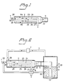
- Figure 1 illustrates an air humidifier, and
- Figure 2 illustrates a liquid cleansing apparatus.
- The air humidifier illustrated in Figure 1 includes a liquid (water)
inlet 1 and anevaporator 2, theinput side 21 of which is connected to theinlet 1 and which includes liquid-restraining wales - Arranged adjacent the
input side 21 of the evaporator is aninlet 28 through which gas flows into the evaporator, the gas in this case being air. Extending between theinput side 21 and theoutput side 22 of theevaporator 2 are channels, shown in broken lines, which are defined in part by the liquid-restraining, vapour-permeable walls inlet 28 and carry vapour which has permeated through thewalls output side 22 of the evaporator and into the surrounding room or space. - Although the level of humidity can be adjusted manually, e.g. by adjusting the quantities of air and/or water used, it is preferred to effect these adjustments automatically with the aid of a humidity gauge and control devices which control automatically, e.g., the temperature to which the incoming water is heated through the intermediary of the illustrated
heating elements - In the case of domestic installations, the exemplifying humidifier may be placed vertically and water introduced through the
conduit 27. This water will run slowly down through theevaporator 2, in the opposite direction to the full arrows, wherewith part of the water will vaporize and pass in vapor form through thepermeable walls fan 5 may be mounted on theoutput side 5, in the illustrated manner. - Alternatively, the humidifier may be installed with the evaporator extending horizontally and forming part of a ventilation system.
- The water vapour engendered by the described and illustrated humidifier will be completely free from bacteria and virus.
- Figure 2 illustrates a further example of how the inventive concept can be applied. Thus, Figure 2 illustrates schematically a liquid cleansing apparatus which comprises an
inlet 1 for the liquid (liquids) to be cleansed (separated), anevaporator 2, theinput side 21 of which is connected to theinlet 1, acondensation chamber 3, which is connected to theoutput side 22 of theevaporator 2, and a closed loop 4 through which gas is conducted between theoutput side 22 and theinput side 21 of theevaporator 2. - Extending between the
input side 21 and theoutput side 22 of theevaporator 2 are first channels which conduct the liquid arriving through theinlet 1, e.g. contaminated water having a temperature of 40°C, and which are defined by respective walls 23-24, 25-26 made of a vapor-permeable and hydrophobic material. Thus, when the apparatus is in operation, the water will pass along the channels and part of the water will vaporize and pass in vapour form through the channel-defining walls 23-26, while the remainder of the water will be led away through anoutlet 27 located on theoutput side 22 of the evaporator. Arranged on theinput side 21 of theevaporator 2 is agas inlet 28 together with second channels, e.g. channels 23-29, 26-29, for conducting the gas through the evaporator. These second channels are thus defined partially by the walls 23-26 and partially by theexternal wall 29 of theevaporator 2. - The loop 4 incorporates at a first location between the
evaporator 2 and the chamber 3 a fan means 5 by means of which the vapour and gas mixture is transported to thecondensing chamber 3, and at a second location downstream of thechamber 3 incorporates a pressure andtemperature regulator 7. The vapour and gas mixture is thus transported by means of thefan 5 to thechamber 3, in which the vapour separates from the gas and the gas bubbles up through thewater 31 and passes through the upper part of the conduit 4 for re-use in the system. The cleansed water departs from the chamber through a separate clean-water outlet 33. - The
condensing chamber 3 comprises a vessel which contains cool distillate and in which the incoming vapour condenses. Arranged closely adjacent the bottom of the vessel is an hydrophobic membrane 32 through which the vapour and gas mixture passes. - The
condensing chamber 3 and theevaporator outlet 27 are cooled with the aid of a heat pump 6 or some equivalent device and the heat recovered therewith (at 61 and 62 respectively) is used for heating the water entering through the inlet 1 (at 63). - It will be understood that many modifications can be made within the scope of the inventive concept. For example, the channels which conduct the incoming liquid and which together form a closed chamber having both an inlet and an outlet may have a rectangular, cylindrical or helical shape. As beforementioned, the apparatus may also be used to separate one liquid from another, in which case the liquid fed to the
inlet 1 will have several liquid constituents. Furthermore, the pressure and temperature in the evaporator and in the condensing chamber respectively may be adjusted to values at which one liquid at a time is distilled from the "liquid" entering through theinlet 1. - The hydrophobic material used for the vapour-permeable walls may be a polytetrafluoroethylene having a pore size of five µm and a porosity of 95 %.
- The temperature of the liquid will normally lie within the range of 70 to 80°, and the water pressure will be suitably atmospheric pressure. In order to prevent clogging of the membrane, the amount of water recovered is preferably maintained at 50 to 70 % by volume. The water may be heated by microwave energy, in many cases.
Claims (6)
- A liquid evaporating apparatus comprising an evaporator (2) having:
a single gas chamber, provided with a gas inlet (28) and a gas outlet (22);
a liquid chamber provided with an inlet (1) for and adapted to contain an aqueous liquid to be evaporated, said chambers being separated from one another by a semipermeable membrane (23-26); and
means (5) for creating a gas flow through the gas chamber to entrain vapour which has permeated through said semipermeable material and to pass gas and entrained vapour out through said gas chamber outlet (22), characterized in that
the liquid chamber is formed by a plurality of liquid channels arranged in said single gas chamber,
wherein the liquid-retaining walls (23-26) of said channels are made of said vapour-permeable, hydrophobic membrane, and wherein the liquid chamber is provided with a liquid outlet (27) to allow liquid intended to be evaporated to pass along the channels and out through said liquid outlet. - Apparatus according to claim 1, intended for cleansing a liquid, characterized in that the gas chamber outlet (22) of the evaporator (2) is connected to a condensing chamber (3).
- Apparatus according to claim 2, characterized by a closed gas loop (4) which is located between the inlet (28) and outlet (22) of the evaporator (2) and which incorporates fan means (5) for transporting gas mixed with vapour to the condensing chamber (3).
- Apparatus according to claim 3, characterized in that the condensing chamber (3) contains a liquid bath (31) which consists of previously condensed vapour and which is in communication with the output side of the evaporator (2), such that vapour contained in the gas will condense upon contact with said bath in the chamber (3).
- Apparatus according to claim 4, characterized by a vapour-permeable hydrophobic membrane arranged between the output side (22) of the evaporator (2) and the liquid bath (31).
- Apparatus according to any of claims 2-5, characterized by a heat pump (6) or some equivalent device by means of which heat is transported from the condensing chamber (3) and a liquid outlet (27) on the output side (22) of the evaporator (2) in closed system to the liquid inlet (1) on the input side (21) of the evaporator (2).
Applications Claiming Priority (2)
| Application Number | Priority Date | Filing Date | Title |
|---|---|---|---|
| SE8701106A SE461443B (en) | 1987-03-17 | 1987-03-17 | DEVICE FOR EVAPORATION OF LIQUID |
| SE8701106 | 1987-03-17 |
Publications (2)
| Publication Number | Publication Date |
|---|---|
| EP0363371A1 EP0363371A1 (en) | 1990-04-18 |
| EP0363371B1 true EP0363371B1 (en) | 1993-09-29 |
Family
ID=20367895
Family Applications (1)
| Application Number | Title | Priority Date | Filing Date |
|---|---|---|---|
| EP88902963A Expired - Lifetime EP0363371B1 (en) | 1987-03-17 | 1988-03-08 | Liquid evaporating apparatus |
Country Status (4)
| Country | Link |
|---|---|
| EP (1) | EP0363371B1 (en) |
| DE (1) | DE3884616T2 (en) |
| SE (1) | SE461443B (en) |
| WO (1) | WO1988006912A1 (en) |
Families Citing this family (9)
| Publication number | Priority date | Publication date | Assignee | Title |
|---|---|---|---|---|
| CA1334016C (en) * | 1987-10-26 | 1995-01-17 | Brian Hartley Keane | Low pressure distillation apparatus |
| DE68905871D1 (en) * | 1988-07-08 | 1993-05-13 | Konishiroku Photo Ind | DEVICE AND METHOD FOR TREATING WASTEWATER FROM PHOTOPROCESSES. |
| US5348691A (en) * | 1993-06-11 | 1994-09-20 | United Technologies Corporation | Atmosphere membrane humidifier and method and system for producing humidified air |
| FR2739614B1 (en) * | 1995-07-05 | 1997-11-14 | Pannier Laurent Alain Charles | DEVICE FOR OBTAINING FRESH WATER FROM NON-CONSUMABLE WATER |
| GB0304373D0 (en) * | 2003-02-26 | 2003-04-02 | Sonander Sven O | Water desalination |
| WO2016180387A1 (en) * | 2015-05-13 | 2016-11-17 | Westfälische Hochschule Gelsenkirchen Bocholt Recklinghausen | Carrier gas-driven atomization process and apparatus |
| CH711934A2 (en) | 2015-12-18 | 2017-06-30 | Condair Group Ag | Method and device for air humidification by means of a hydrophobic, microporous membrane. |
| CN111170386B (en) * | 2018-11-13 | 2022-09-30 | 上海景峰制药有限公司 | Drawer type water organic solvent evaporation device |
| CN111170388A (en) * | 2018-11-13 | 2020-05-19 | 上海景峰制药有限公司 | Organic solvent evaporation plant in water |
Family Cites Families (4)
| Publication number | Priority date | Publication date | Assignee | Title |
|---|---|---|---|---|
| US3532270A (en) * | 1969-02-03 | 1970-10-06 | Us Navy | Partial pressure low level humidity generator |
| DE2644226A1 (en) * | 1976-09-30 | 1978-04-06 | Linde Ag | METHOD AND DEVICE FOR HUMIDIFYING AIR |
| SE452451B (en) * | 1984-06-07 | 1987-11-30 | Svenska Utvecklings Ab | MEMBRANE STILLATION DEVICE |
| SE447728B (en) * | 1985-06-17 | 1986-12-08 | Svenska Utvecklings Ab | DISTILLATION DEVICE FOR THE DISTILLATION OF LIQUID CONTAINING A MEMBRANE |
-
1987
- 1987-03-17 SE SE8701106A patent/SE461443B/en not_active IP Right Cessation
-
1988
- 1988-03-08 WO PCT/SE1988/000110 patent/WO1988006912A1/en not_active Ceased
- 1988-03-08 EP EP88902963A patent/EP0363371B1/en not_active Expired - Lifetime
- 1988-03-08 DE DE88902963T patent/DE3884616T2/en not_active Expired - Fee Related
Also Published As
| Publication number | Publication date |
|---|---|
| WO1988006912A1 (en) | 1988-09-22 |
| SE461443B (en) | 1990-02-19 |
| DE3884616D1 (en) | 1993-11-04 |
| SE8701106D0 (en) | 1987-03-17 |
| EP0363371A1 (en) | 1990-04-18 |
| SE8701106L (en) | 1988-09-18 |
| DE3884616T2 (en) | 1994-04-28 |
Similar Documents
| Publication | Publication Date | Title |
|---|---|---|
| US5290403A (en) | Liquid evaporating apparatus | |
| US3351120A (en) | Multiple effect, multi-stage flash and film evaporator | |
| US20150329377A1 (en) | Systems including a condensing apparatus such as a bubble column condenser | |
| US5232085A (en) | Distillation system with a hydrophobic porous membrane | |
| US5906714A (en) | Method for treating emulsified liquids | |
| EP0363371B1 (en) | Liquid evaporating apparatus | |
| US4525243A (en) | Apparatus for desalinating water | |
| US4217176A (en) | Evaporator | |
| US3843463A (en) | Evaporative method | |
| US4976824A (en) | Water distillation and aeration apparatus | |
| US3896004A (en) | Distillation system utilizing a microporous stack | |
| US3849259A (en) | Distillation apparatus | |
| US3300392A (en) | Vacuum distillation including predegasification of distilland | |
| US4364794A (en) | Liquid concentration apparatus | |
| CA2439996C (en) | Pervaporation apparatus and method | |
| US3337421A (en) | Directly contacting feed liquid with vaporized heat exchange liquid immiscible with feed | |
| US4285776A (en) | Desalation system | |
| JPH10263301A (en) | Liquid thickening | |
| KR970010160B1 (en) | Distillation apparatus and distillation method | |
| CA2362120C (en) | Device for cleaning a fluid in the form of a vapor from a circuit | |
| CN111960488B (en) | Sewage treatment device and method | |
| CN214004103U (en) | Dilute sulfuric acid effluent disposal system | |
| US4265701A (en) | Liquid concentration method | |
| US3454470A (en) | Distillation of liquids using semi-porous and non-porous conduits in vacuum pressure container | |
| GB2084885A (en) | Process for the concentration of aqueous glycol solutions |
Legal Events
| Date | Code | Title | Description |
|---|---|---|---|
| PUAI | Public reference made under article 153(3) epc to a published international application that has entered the european phase |
Free format text: ORIGINAL CODE: 0009012 |
|
| 17P | Request for examination filed |
Effective date: 19890911 |
|
| AK | Designated contracting states |
Kind code of ref document: A1 Designated state(s): DE GB NL |
|
| 17Q | First examination report despatched |
Effective date: 19910822 |
|
| GRAA | (expected) grant |
Free format text: ORIGINAL CODE: 0009210 |
|
| AK | Designated contracting states |
Kind code of ref document: B1 Designated state(s): DE GB NL |
|
| REF | Corresponds to: |
Ref document number: 3884616 Country of ref document: DE Date of ref document: 19931104 |
|
| PLBE | No opposition filed within time limit |
Free format text: ORIGINAL CODE: 0009261 |
|
| STAA | Information on the status of an ep patent application or granted ep patent |
Free format text: STATUS: NO OPPOSITION FILED WITHIN TIME LIMIT |
|
| 26N | No opposition filed | ||
| PGFP | Annual fee paid to national office [announced via postgrant information from national office to epo] |
Ref country code: GB Payment date: 20010216 Year of fee payment: 14 |
|
| PGFP | Annual fee paid to national office [announced via postgrant information from national office to epo] |
Ref country code: DE Payment date: 20010316 Year of fee payment: 14 |
|
| PGFP | Annual fee paid to national office [announced via postgrant information from national office to epo] |
Ref country code: NL Payment date: 20010319 Year of fee payment: 14 |
|
| REG | Reference to a national code |
Ref country code: GB Ref legal event code: IF02 |
|
| PG25 | Lapsed in a contracting state [announced via postgrant information from national office to epo] |
Ref country code: GB Free format text: LAPSE BECAUSE OF NON-PAYMENT OF DUE FEES Effective date: 20020308 |
|
| PG25 | Lapsed in a contracting state [announced via postgrant information from national office to epo] |
Ref country code: NL Free format text: LAPSE BECAUSE OF NON-PAYMENT OF DUE FEES Effective date: 20021001 Ref country code: DE Free format text: LAPSE BECAUSE OF NON-PAYMENT OF DUE FEES Effective date: 20021001 |
|
| GBPC | Gb: european patent ceased through non-payment of renewal fee |
Effective date: 20020308 |
|
| NLV4 | Nl: lapsed or anulled due to non-payment of the annual fee |
Effective date: 20021001 |