EP0363159A2 - Method of dimensionally stabilizing interface between dissimilar metals in an internal combustion engine - Google Patents
Method of dimensionally stabilizing interface between dissimilar metals in an internal combustion engine Download PDFInfo
- Publication number
- EP0363159A2 EP0363159A2 EP89310121A EP89310121A EP0363159A2 EP 0363159 A2 EP0363159 A2 EP 0363159A2 EP 89310121 A EP89310121 A EP 89310121A EP 89310121 A EP89310121 A EP 89310121A EP 0363159 A2 EP0363159 A2 EP 0363159A2
- Authority
- EP
- European Patent Office
- Prior art keywords
- metal
- insert
- interface
- tec
- fibers
- Prior art date
- Legal status (The legal status is an assumption and is not a legal conclusion. Google has not performed a legal analysis and makes no representation as to the accuracy of the status listed.)
- Granted
Links
Images


Classifications
-
- F—MECHANICAL ENGINEERING; LIGHTING; HEATING; WEAPONS; BLASTING
- F02—COMBUSTION ENGINES; HOT-GAS OR COMBUSTION-PRODUCT ENGINE PLANTS
- F02F—CYLINDERS, PISTONS OR CASINGS, FOR COMBUSTION ENGINES; ARRANGEMENTS OF SEALINGS IN COMBUSTION ENGINES
- F02F7/00—Casings, e.g. crankcases or frames
- F02F7/0085—Materials for constructing engines or their parts
- F02F7/0087—Ceramic materials
-
- F—MECHANICAL ENGINEERING; LIGHTING; HEATING; WEAPONS; BLASTING
- F02—COMBUSTION ENGINES; HOT-GAS OR COMBUSTION-PRODUCT ENGINE PLANTS
- F02F—CYLINDERS, PISTONS OR CASINGS, FOR COMBUSTION ENGINES; ARRANGEMENTS OF SEALINGS IN COMBUSTION ENGINES
- F02F7/00—Casings, e.g. crankcases or frames
- F02F7/0043—Arrangements of mechanical drive elements
- F02F7/0053—Crankshaft bearings fitted in the crankcase
-
- F—MECHANICAL ENGINEERING; LIGHTING; HEATING; WEAPONS; BLASTING
- F16—ENGINEERING ELEMENTS AND UNITS; GENERAL MEASURES FOR PRODUCING AND MAINTAINING EFFECTIVE FUNCTIONING OF MACHINES OR INSTALLATIONS; THERMAL INSULATION IN GENERAL
- F16C—SHAFTS; FLEXIBLE SHAFTS; ELEMENTS OR CRANKSHAFT MECHANISMS; ROTARY BODIES OTHER THAN GEARING ELEMENTS; BEARINGS
- F16C17/00—Sliding-contact bearings for exclusively rotary movement
- F16C17/12—Sliding-contact bearings for exclusively rotary movement characterised by features not related to the direction of the load
- F16C17/22—Sliding-contact bearings for exclusively rotary movement characterised by features not related to the direction of the load with arrangements compensating for thermal expansion
-
- F—MECHANICAL ENGINEERING; LIGHTING; HEATING; WEAPONS; BLASTING
- F16—ENGINEERING ELEMENTS AND UNITS; GENERAL MEASURES FOR PRODUCING AND MAINTAINING EFFECTIVE FUNCTIONING OF MACHINES OR INSTALLATIONS; THERMAL INSULATION IN GENERAL
- F16C—SHAFTS; FLEXIBLE SHAFTS; ELEMENTS OR CRANKSHAFT MECHANISMS; ROTARY BODIES OTHER THAN GEARING ELEMENTS; BEARINGS
- F16C9/00—Bearings for crankshafts or connecting-rods; Attachment of connecting-rods
- F16C9/02—Crankshaft bearings
-
- F—MECHANICAL ENGINEERING; LIGHTING; HEATING; WEAPONS; BLASTING
- F02—COMBUSTION ENGINES; HOT-GAS OR COMBUSTION-PRODUCT ENGINE PLANTS
- F02F—CYLINDERS, PISTONS OR CASINGS, FOR COMBUSTION ENGINES; ARRANGEMENTS OF SEALINGS IN COMBUSTION ENGINES
- F02F2200/00—Manufacturing
- F02F2200/06—Casting
-
- F—MECHANICAL ENGINEERING; LIGHTING; HEATING; WEAPONS; BLASTING
- F05—INDEXING SCHEMES RELATING TO ENGINES OR PUMPS IN VARIOUS SUBCLASSES OF CLASSES F01-F04
- F05C—INDEXING SCHEME RELATING TO MATERIALS, MATERIAL PROPERTIES OR MATERIAL CHARACTERISTICS FOR MACHINES, ENGINES OR PUMPS OTHER THAN NON-POSITIVE-DISPLACEMENT MACHINES OR ENGINES
- F05C2201/00—Metals
- F05C2201/02—Light metals
- F05C2201/021—Aluminium
-
- F—MECHANICAL ENGINEERING; LIGHTING; HEATING; WEAPONS; BLASTING
- F05—INDEXING SCHEMES RELATING TO ENGINES OR PUMPS IN VARIOUS SUBCLASSES OF CLASSES F01-F04
- F05C—INDEXING SCHEME RELATING TO MATERIALS, MATERIAL PROPERTIES OR MATERIAL CHARACTERISTICS FOR MACHINES, ENGINES OR PUMPS OTHER THAN NON-POSITIVE-DISPLACEMENT MACHINES OR ENGINES
- F05C2201/00—Metals
- F05C2201/04—Heavy metals
- F05C2201/0433—Iron group; Ferrous alloys, e.g. steel
- F05C2201/0436—Iron
-
- F—MECHANICAL ENGINEERING; LIGHTING; HEATING; WEAPONS; BLASTING
- F05—INDEXING SCHEMES RELATING TO ENGINES OR PUMPS IN VARIOUS SUBCLASSES OF CLASSES F01-F04
- F05C—INDEXING SCHEME RELATING TO MATERIALS, MATERIAL PROPERTIES OR MATERIAL CHARACTERISTICS FOR MACHINES, ENGINES OR PUMPS OTHER THAN NON-POSITIVE-DISPLACEMENT MACHINES OR ENGINES
- F05C2203/00—Non-metallic inorganic materials
- F05C2203/08—Ceramics; Oxides
- F05C2203/0804—Non-oxide ceramics
- F05C2203/083—Nitrides
- F05C2203/0843—Nitrides of silicon
-
- F—MECHANICAL ENGINEERING; LIGHTING; HEATING; WEAPONS; BLASTING
- F05—INDEXING SCHEMES RELATING TO ENGINES OR PUMPS IN VARIOUS SUBCLASSES OF CLASSES F01-F04
- F05C—INDEXING SCHEME RELATING TO MATERIALS, MATERIAL PROPERTIES OR MATERIAL CHARACTERISTICS FOR MACHINES, ENGINES OR PUMPS OTHER THAN NON-POSITIVE-DISPLACEMENT MACHINES OR ENGINES
- F05C2203/00—Non-metallic inorganic materials
- F05C2203/08—Ceramics; Oxides
- F05C2203/0865—Oxide ceramics
- F05C2203/0869—Aluminium oxide
-
- F—MECHANICAL ENGINEERING; LIGHTING; HEATING; WEAPONS; BLASTING
- F05—INDEXING SCHEMES RELATING TO ENGINES OR PUMPS IN VARIOUS SUBCLASSES OF CLASSES F01-F04
- F05C—INDEXING SCHEME RELATING TO MATERIALS, MATERIAL PROPERTIES OR MATERIAL CHARACTERISTICS FOR MACHINES, ENGINES OR PUMPS OTHER THAN NON-POSITIVE-DISPLACEMENT MACHINES OR ENGINES
- F05C2251/00—Material properties
- F05C2251/04—Thermal properties
- F05C2251/042—Expansivity
-
- F—MECHANICAL ENGINEERING; LIGHTING; HEATING; WEAPONS; BLASTING
- F05—INDEXING SCHEMES RELATING TO ENGINES OR PUMPS IN VARIOUS SUBCLASSES OF CLASSES F01-F04
- F05C—INDEXING SCHEME RELATING TO MATERIALS, MATERIAL PROPERTIES OR MATERIAL CHARACTERISTICS FOR MACHINES, ENGINES OR PUMPS OTHER THAN NON-POSITIVE-DISPLACEMENT MACHINES OR ENGINES
- F05C2253/00—Other material characteristics; Treatment of material
- F05C2253/16—Fibres
-
- Y—GENERAL TAGGING OF NEW TECHNOLOGICAL DEVELOPMENTS; GENERAL TAGGING OF CROSS-SECTIONAL TECHNOLOGIES SPANNING OVER SEVERAL SECTIONS OF THE IPC; TECHNICAL SUBJECTS COVERED BY FORMER USPC CROSS-REFERENCE ART COLLECTIONS [XRACs] AND DIGESTS
- Y10—TECHNICAL SUBJECTS COVERED BY FORMER USPC
- Y10T—TECHNICAL SUBJECTS COVERED BY FORMER US CLASSIFICATION
- Y10T29/00—Metal working
- Y10T29/49—Method of mechanical manufacture
- Y10T29/49229—Prime mover or fluid pump making
- Y10T29/49231—I.C. [internal combustion] engine making
-
- Y—GENERAL TAGGING OF NEW TECHNOLOGICAL DEVELOPMENTS; GENERAL TAGGING OF CROSS-SECTIONAL TECHNOLOGIES SPANNING OVER SEVERAL SECTIONS OF THE IPC; TECHNICAL SUBJECTS COVERED BY FORMER USPC CROSS-REFERENCE ART COLLECTIONS [XRACs] AND DIGESTS
- Y10—TECHNICAL SUBJECTS COVERED BY FORMER USPC
- Y10T—TECHNICAL SUBJECTS COVERED BY FORMER US CLASSIFICATION
- Y10T29/00—Metal working
- Y10T29/49—Method of mechanical manufacture
- Y10T29/49229—Prime mover or fluid pump making
- Y10T29/49249—Piston making
- Y10T29/49256—Piston making with assembly or composite article making
- Y10T29/49259—Piston making with assembly or composite article making with fiber reinforced structure
-
- Y—GENERAL TAGGING OF NEW TECHNOLOGICAL DEVELOPMENTS; GENERAL TAGGING OF CROSS-SECTIONAL TECHNOLOGIES SPANNING OVER SEVERAL SECTIONS OF THE IPC; TECHNICAL SUBJECTS COVERED BY FORMER USPC CROSS-REFERENCE ART COLLECTIONS [XRACs] AND DIGESTS
- Y10—TECHNICAL SUBJECTS COVERED BY FORMER USPC
- Y10T—TECHNICAL SUBJECTS COVERED BY FORMER US CLASSIFICATION
- Y10T29/00—Metal working
- Y10T29/49—Method of mechanical manufacture
- Y10T29/4998—Combined manufacture including applying or shaping of fluent material
- Y10T29/49988—Metal casting
Definitions
- a rigid interface exists between an aluminum head and an iron-based cylinder block, joined by steel bolts with a gasket interposed therebetween.
- a rigid interface may exist between an aluminum cylinder block and cast-iron main bearing caps attached to the block by steel bolts.
- the coefficient of thermal expansion of the steel bolts, or of the cast-iron part, relative to the aluminum part, differs considerably and may result in widely differing clamping forces between the parts. The interface can loosen under some temperature conditions that may cause engine performance problems.
- Moving interfaces exist between rotating members and their bearings or between a reciprocating piston and its bore walls.
- the prior art has attempted to modify the absorption of impact stress at such interface to eliminate gradual distortion of the support.
- U.S. patent 3,089,735 a bearing support insert is used to provide a greater outer surface area than inner surface area.
- a cast-in-place insert comprised of aluminum or magnesium is kneaded to have high compression resistance; it is preferably bonded during casting of the block by use of lead, cadmium, tin or zinc. No attempt is made to substantially modify the thermal expansion characteristic of the block at the interface by material substitution.
- metal matrix composites which change the physical characteristics of the metal matrix by introducing a ceramic phase
- little application research has been carried out to adapt such technology to dissimilar metal interfaces which may be employed in an internal combustion engine.
- the primary goal of this invention is (i) to modify the thermal expansion characteristic of at least one part of an interface between dissimilar metals to make them dimensionally compatible at varying temperature conditions, and (ii) to do so by cast-in-place techniques that avoid the buildup of internal stresses that lead to breakage or delamination.
- the fibers are aligned generally along the direction of extrusion; the insert is taken from the extruded strand by severing and shaped, if necessary, to orient its fibers generally in-line with at least one direction of thermal growth that may interfere with the interface.
- the insert is located in a mould for being cast-in-place to carry out the predetermined fiber orientation; the insert is preheated to a temperature approximately 35-45% of the temperature of the molten metal of the higher TEC.
- the metal powder may be rapidly solidified and devoid of organic material.
- the thermal shock of the molten metal of higher TEC (introduced into the mould) will, upon contact with the insert, break up any oxide coating covering the molten metal to create improved wetability and bonding.
- the metal of the higher TEC is an aluminum alloy, thus permitting hot extrusion to be carried out using greater than 10:1 reduction, i.e., 30-50 ksi pressure, and at a temperature greater than 400°C, preferably 500-600°C.
- the ceramic fibers may preferably be selected from the group consisting of silicon nitride, sialon, silicon carbide, aluminum silicate and alumina.
- the metal powder may be a metal form or alloy selected from the group consisting of aluminum, titanium, magnesium, copper, and zinc.
- an insert for an aluminum metal part is shaped by heating to a temperature of about 300°C for about 20 minutes and bending the insert to conform to the desired configuration.
- the insert may be arc-shaped and totally immersed as an embedment within a casting used for a rotating bearing support.
- the insert may be shaped as a cylinder to be deployed as a bushing and exposed at a rigid interfacing surface.
- Candidate fibers include sialon, silicon nitride, silicon carbide, aluminosilicates, and alumina. As shown in Table I, their coefficients of thermal expansion are 3.0 x 10 ⁇ 6/°C, 3.3 x 10 ⁇ 6/°C, 4.3 x 10 ⁇ 6/°C, 5.1 x 10 ⁇ 6/°C, and 8.1 x 10 ⁇ 6/°C, respectively, each of which is smaller than that of the thermal coefficient of expansion for cast-iron. Also, each has a strength and modulus of elasticity which is high for supporting the stresses induced when restricting the thermal expansion of the aluminum alloy matrix during heating; this is important for engine bearing applications.
- the green body 40 is hot extruded by being passed through a die opening 42 of die 41 using a power feed 43.
- the reduction ratio of the hot extrusion process should be greater than 10:1.
- Extrusion is carried out at a temperature between 500-600°C at a pressure of 20-40 ksi for Al metal matrix composites; extrusion of titanium may be at a temperature of about 500-700°C and at a pressure of about 50 ksi. Such temperatures are achieved by use of an induction heater 44.
- the output of the die will be a continuous billet 45 having higher percent fiber orientation and greater unidirectional strength along its axis 46 than conventional powder metallurgy composites.
- the same mixture, ceramic fibers and metal alloy powder, compaction pressures, and hot extrusion pressures are used for the making of the inserts.
- the extrusion is of a hollow cylinder with the fibers 65 oriented in a direction parallel to axis 63 of the cylinder. In this manner, the fibers will be generally parallel to the direction of anticipated thermal growth at the threaded interface which may interfere with bolt tension.
- Iron, aluminum and composite aluminum metal matrix composite inserts were made into test castings and bolted together for testing.
- the metal matrix composite for these castings was comprised of 20 volume percent SiC in a 6061 rapidly solidified Al powder.
- the bore diameters of all three assemblies were measured as a function of temperature over the range from -40 to -400°F.
- a telescoping gauge was used to measure the bore diameter at three orientations. From these measurements, the mean bore diameter for each temperature was calculated. This information was then used to determine (for each material): the diametrical strain, the TEC, and an estimate of the main bearing/crankshaft running clearances at temperature ranging from -40°F to 300°F (see Table II).
Landscapes
- Engineering & Computer Science (AREA)
- General Engineering & Computer Science (AREA)
- Mechanical Engineering (AREA)
- Chemical & Material Sciences (AREA)
- Combustion & Propulsion (AREA)
- Ceramic Engineering (AREA)
- Manufacture Of Alloys Or Alloy Compounds (AREA)
- Cylinder Crankcases Of Internal Combustion Engines (AREA)
Abstract
Description
- This invention relates to the art of interfacing metals having differing thermal expansion characteristics and, more particularly, to the art of compensating for such differences in thermal expansion when such joined metals are used at widely varying temperature conditions.
- In modern internal combustion engines, dissimilar metal interfaces have included both rigid and moving interfaces. A rigid interface exists between an aluminum head and an iron-based cylinder block, joined by steel bolts with a gasket interposed therebetween. Similarly, a rigid interface may exist between an aluminum cylinder block and cast-iron main bearing caps attached to the block by steel bolts. The coefficient of thermal expansion of the steel bolts, or of the cast-iron part, relative to the aluminum part, differs considerably and may result in widely differing clamping forces between the parts. The interface can loosen under some temperature conditions that may cause engine performance problems.
- Attempts have been made to use gasket materials with excessively low relaxation rates at the rigid head-to-block interface and thereby maintain a more uniform level of bolt forces (see SAE article "Aluminum Engines Require Special Gasketing Techniques", Vol. 91, No. 4, pp. 48-50, 1983). Such techniques are expensive and not totally satisfactory to eliminate all leakage. Other attempts to improve rigid interfaces have included the use of inserts having high resistance to creep which have been cast-in-place in an aluminum head to avoid plastic deformation of the head under the stress of steel bolts (see U.S. patent 4,450,800). The insert in this disclosure is comprised of nickel and iron providing a coefficient of thermal expansion the same as the aluminum head but with greater pressure resistance than aluminum. This, in no way, modifies the thermal expansion characteristic of either interfacing part, thus resulting in the same propensity to looseness.
- Moving interfaces exist between rotating members and their bearings or between a reciprocating piston and its bore walls. At the interface between an iron crankshaft and an aluminum bearing support, the prior art has attempted to modify the absorption of impact stress at such interface to eliminate gradual distortion of the support. In U.S. patent 3,089,735, a bearing support insert is used to provide a greater outer surface area than inner surface area. In this disclosure, a cast-in-place insert comprised of aluminum or magnesium is kneaded to have high compression resistance; it is preferably bonded during casting of the block by use of lead, cadmium, tin or zinc. No attempt is made to substantially modify the thermal expansion characteristic of the block at the interface by material substitution.
- Although metal matrix composites are known which change the physical characteristics of the metal matrix by introducing a ceramic phase, little application research has been carried out to adapt such technology to dissimilar metal interfaces which may be employed in an internal combustion engine.
- Accordingly, the primary goal of this invention is (i) to modify the thermal expansion characteristic of at least one part of an interface between dissimilar metals to make them dimensionally compatible at varying temperature conditions, and (ii) to do so by cast-in-place techniques that avoid the buildup of internal stresses that lead to breakage or delamination.
- A primary aspect of this invention is a method of dimensionally stabilizing the interface between metal parts of differing thermal expansion characteristics or coefficients (TEC), regardless of temperature variations under normal designed use of such parts. The method comprises: (a) casting molten metal, for a first part having the higher TEC, about an insert consisting of (i) a metal matrix comprised of a metal substantially the same as the metal having the higher TEC, and (ii) ceramic fibers generally having a TEC substantially less than either of said parts, the fibers of the insert being generally aligned with at least one direction of anticipated thermal growth of the part having the higher TEC that may interfere with the interface, thereby to modify the TEC of the first part adjacent the interface; and (b) operatively assembling together the parts to form the interface. The casting step is desirably preceded by extruding a mixture of metal powder and ceramic fibers, the metal powder having a TEC similar to the metal part having the higher TEC.
- The fibers are aligned generally along the direction of extrusion; the insert is taken from the extruded strand by severing and shaped, if necessary, to orient its fibers generally in-line with at least one direction of thermal growth that may interfere with the interface. The insert is located in a mould for being cast-in-place to carry out the predetermined fiber orientation; the insert is preheated to a temperature approximately 35-45% of the temperature of the molten metal of the higher TEC. The metal powder may be rapidly solidified and devoid of organic material. Advantageously, the thermal shock of the molten metal of higher TEC (introduced into the mould) will, upon contact with the insert, break up any oxide coating covering the molten metal to create improved wetability and bonding.
- Preferably, the metal of the higher TEC is an aluminum alloy, thus permitting hot extrusion to be carried out using greater than 10:1 reduction, i.e., 30-50 ksi pressure, and at a temperature greater than 400°C, preferably 500-600°C. The ceramic fibers may preferably be selected from the group consisting of silicon nitride, sialon, silicon carbide, aluminum silicate and alumina. The metal powder may be a metal form or alloy selected from the group consisting of aluminum, titanium, magnesium, copper, and zinc.
- Advantageously, an insert for an aluminum metal part is shaped by heating to a temperature of about 300°C for about 20 minutes and bending the insert to conform to the desired configuration. The insert may be arc-shaped and totally immersed as an embedment within a casting used for a rotating bearing support. Alternatively, the insert may be shaped as a cylinder to be deployed as a bushing and exposed at a rigid interfacing surface.
- Preferably, the insert is moulded to the cast metal part by die-casting techniques. When introducing molten metal, of an aluminum base, the pouring temperature is in the range of 750-760°F (398-404°C) with the insert being heated to a temperature in the range of 262-342°F (128-172°C).
- Another aspect of this invention is the provision of a novel assembly for an internal combustion engine having interfacing metals of differing TEC, comprising: (a) a first part comprised of a metal having the lower TEC and presenting a first interface surface; (b) a second part comprised of a metal having the higher TEC and presenting a second interface surface to mate with the first interface surface, the second part having a cast-in-place metal matrix composite insert in which the metal matrix is comprised of substantially the same as the metal of said second part, said insert containing a ceramic phase consisting of ceramic fibers aligned generally in at least one direction of anticipated thermal growth of the first part that may interfere with the interface.
- The invention will now be described further, by way of example, with reference to the accompanying drawings, in which :
- Figure 1 is a flow diagram of the method steps of this invention;
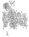
- Figure 2 is an exploded view of parts of an internal combustion engine showing locations for applying this invention within such engine;
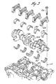
- Figure 3 is an enlarged perspective exploded view of the bottom of an aluminum cylinder block showing main bearing supports and bearing caps with cast-in-place inserts of this invention;
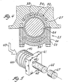
- Figure 4 is an enlarged sectional view taken centrally through one of the main bearings of Figure 3 showing the use of totally immersed or embedded inserts to control thermal expansion for a moving interface application;
- Figure 5 shows schematically a mode for carrying out hot extrusion;
- Figure 6 is a perspective view of fixture parts used to shape an insert for a bearing cap application;
- Figure 7 is a perspective view showing a mould fixture and inserts for making both a moving interface and a rigid interface application;
- Figure 8 is a schematic view, partially in section, of a block and aluminum head for an engine assembly showing rigid interface applications of the invention;
- Figures 9 and 10 are photographs at different magnifications of metallographic cross-sections for the structure of Figure 3 showing the bonding of the insert to the cast part; and
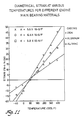
- Figure 11 is a graphical illustration of strain at various temperatures for different engine bearing materials.
- Interfacing metals of differing thermal expansion characteristics or coefficient (TEC), such as aluminum and iron, in an internal combustion engine may lead to poor performance. In rigid interfacings, such as when using metal fasteners to bolt together components with TEC significantly different than the fasteners, it is difficult to maintain a consistent clamping force between the components at varying temperature conditions. In moving interfaces, such as iron crankshafts in aluminum bearing supports, performance problems may result from the large difference of coefficient of thermal expansion. Cast iron has a TEC of about 6 x 10⁻⁶/°F or 12 x 10⁻⁶/°C, and aluminum components have a TEC of about 13 x 10⁻⁶/°F or 21 x 10⁻⁶/°C. A main bearing running clearance of .0008 inches diametrically is ideal for good engine performance at normal operating temperatures, but when the aluminum casting is cooled, it will contract too much around the iron crankshaft, decreasing the running clearance to a point where required cold weather starting (-40°F) becomes difficult. Likewise, in above normal or hot running engines, the running clearance can increase to the point where excessive noise and oil consumption will result.
- To overcome these problems, this invention provides a method of deploying ceramic fiber oriented metal matrix composites as inserts in a cast component having the higher coefficient of thermal expansion and which will serve as one of the interfacting metal parts. The cast-in-place inserts will locally reduce the TEC, for the metal of normally higher TEC, at the interface, closer to that of the metal part having the lower TEC, thereby controlling the dimensional fit or running clearance variation to provide good, consistent engine performance.
- The method of this invention can provide for dimensionally stabilizing, against the effects of temperature variations, the interfaces between metal parts of differing thermal expansion characteristics. This is carried out, as shown in Figure 1, by primarily first casting molten metal (for a first part having the higher TEC) about an insert consisting of (i) a matrix of a metal comprised substantially of the metal having the higher TEC, and (ii) ceramic fibers, to form a first part. The fibers are aligned, during casting, to generally coincide with at least one direction of anticipated thermal growth that may interfere with the interface. Secondly, the parts are operatively assembled together to form the interface with the fibers oriented as predetermined. Steps prepartory to casting for making and locating the inserts include first the step of extruding the metal powder similar to the metal having the higher TEC and ceramic fibers to form a billet. Next, the billet is severed to provide an insert and shaping the insert, if necessary, to orient the fibers in a predetermined manner different than what is inherent in the billet. Lastly, locating the insert in a mould to carry out the predetermined fiber orientation, while preheating the insert to 35-45% of the temperature of the molten metal for the first part.
- In modern internal combustion engines there is now employed, at various locations throughout the engine, a mating of metals having dissimilar TEC, such as aluminum and cast-iron or steel. Other light metals such as titanium, magnesium, copper, and zinc may be employed which will have a high TEC. Other metals with low TEC may be employed, such as lead. Figure 2 shows some examples of moving interfaces employing dissimilar metals, which include: (i) the support of a cast-
iron crankshaft 10 by aluminum bearing supports 11 cast integral in an aluminum crankcase 12 and/or employing aluminum main bearing caps 13, preferably cast integral with analuminum oil pan 24, (ii) rotary support of cast-iron camshaft 14 in integrally cast aluminum supports 15, (iii) a reciprocal or sliding interface between analuminum piston 16 and iron liner 17 of acylinder block 18, and (iv) thealuminum piston 16 riding directly against the cylinder bores of an iron block utilizing a ringless piston concept. Examples of rigid interfaces include: (i) a cast-iron exhaust manifold 19 fastened bysteel bolts 20 toaluminum cylinder head 21, (ii) ironmain bearing caps 9 fastened to an aluminum casting forcylinder block 18 by use of steel or iron-based threadedfasteners 22, and (iii) a castaluminum intake manifold 9 fastened to an iron oraluminum cylinder block 18 bysteel bolts 23. In the rigid interface examples, the iron-based fasteners will respond to temperature environments differently than the threaded support comprised of aluminum. This may lead to unusual stress patterns and eventual loosening of the fasteners within the threaded support. - In a moving interface, such as a curved cylindrical surface about a rotatable shaft, the circumference of the interfacing surface of the parts with the higher TEC has to increase or grow at higher temperatures. Therefore, the direction to restrain is a curvilinear one, aligned with the circumference. Thermal growth in other directions perpendicular to such circumference has little effect on an interface of mating cylindrical surfaces. This is true also for a sliding interface, such as a cylindrical piston reciprocating against a cylindrical bore wall in a ringless piston application. In a three-dimensional interface, such as in a universal ball and socket interfit, it may be necessary to restrain thermal growth in two mutually perpendicular but circumferential directions; thus, the fibers must accordingly be aligned in both such directions.
- As shown in Figures 3-4, an
assembly 25 is provided for supporting a first part 26 (comprised of a nodular iron crankshaft) within a second part or assembly 27-28 comprised of aluminum alloy die-cast bearing supports. One of the latter is amain bearing support 27 integrally cast with the aluminum alloy cylinder block, and the other is amain bearing cap 28 cast independently and secured to themain bearing support 27 by suitable threadedfasteners 29. An interface is created between the moving or rotatablefirst part 26 and the fixed second part 27-28, bringing them together with two half-shellbushing type bearings 30 interposed therebetween. The second part 27-28 will experience thermal growth in a three-dimensional mode, but the most critical direction is that which is along the circumference and annular interface. - To achieve dimensional stability of the interface, a metal matrix
composite insert 32 is formed by compacting, hot extrusion, shaping, and then casting it in-place within each of the second parts 27-28. The insert modifies the rate of thermal expansion coefficient for the second part adjacent at the interface to provide dimensional stability in a temperature environment of minus 40°F to 500°F. Such metal matrix composite insert is comprised of amatrix 33 consisting of rapidly solidified aluminum alloy powder andceramic fibers 34 oriented in a predetermined manner. Preferably, the matrix metal is an aluminum alloy consisting of 8-15% (by weight) Si, .5-4.5% Cu, .05-.7% Mg and the remainder Al. The powder is prealloyed and formed by inert gas atomization for rapid solidification. - Candidate fibers include sialon, silicon nitride, silicon carbide, aluminosilicates, and alumina. As shown in Table I, their coefficients of thermal expansion are 3.0 x 10⁻⁶/°C, 3.3 x 10⁻⁶/°C, 4.3 x 10⁻⁶/°C, 5.1 x 10⁻⁶/°C, and 8.1 x 10⁻⁶/°C, respectively, each of which is smaller than that of the thermal coefficient of expansion for cast-iron. Also, each has a strength and modulus of elasticity which is high for supporting the stresses induced when restricting the thermal expansion of the aluminum alloy matrix during heating; this is important for engine bearing applications. By manipulating the content of the fiber versus the matrix, the resulting insert can be selectively tailored to have a coefficient of thermal expansion approach or equal that of cast-iron unidirectionally by controlling the volume percent fiber from 5% to 55%. Selection of ceramic fiber type, matrix alloy, and volume percent, the TEC can be adjusted to match the TEC of many other light metals having high TEC. For example, a blend of 20 volume percent SiC with 6061 rapidly solifidied aluminum alloy yielded an insert TEC of 7/83 10⁻⁶/°F, also shown in Table I.
- The metal matrix powder for the
insert 33 is blended with the ceramic fibers and may be warm or cold pressed to form a green compact structure in preparation for hot extrusion. Full density is necessary to ensure the integrity of the article and attain the necessary mechanical properties for extrusion. Vacuum compaction or isostatic pressing at elevated temperatures and pressures to cure the green structure should not be used to achieve full density in the composite. High temperatures can cause an adverse reaction between the fibers and matrix metal, especially for silicon carbide fibers and reactive metals like aluminum and titanium. Such reaction affects the integrity of the composites and their mechanical properties. Secondary phases, such as carbides, borides, silicides or nitrides, can be formed in these reactive composites and are predictably based upon thermal dynamic considerations. Avoidance of an adverse reaction can be accomplished by plastically deforming the matrix metal to impart a significant strain energy to the metal, mixing the strain energized metal with the ceramic fibers (preferably having an aspect ratio (1/d) of 20-200). Strain energy can be imparted in a number of ways: one way is to pass spherical, prealloyed metal particles through opposed rolls. The strain energy stored in the metal allows subsequent extrusion to occur at lower temperatures so that adverse reactions do not occur between the fibers and the matrix metal. However, plastic deformation is not necessary for making green compacts of aluminum alloy metal and silicon nitride fibers since the alloys have relatively low melting points and are softer than other light metals such as titanium alloys. Even without imparting strain energy to the matrix metals, the processing temperatures can remain low enough that the alloy and silicon nitride fibers will not react and the fibers will not degrade. - Forming composites with continuous or very long fibers often requires highly specialized fabrication techniques to blend the fibers and to avoid (1) fiber breakage, (2) fiber bunching, (3) nonuniform fiber/matrix interfacial bonding, and (4) void concentrations. Semi-long whiskers or particulates are more readily used for hot extrusion of this invention. Agglomeration of the fibers should be avoided during blending; vibrating the mixture has proven as one means to achieve the desired dispersion. Machining, drilling, grinding, joining, and other operations are also more readily accomplished with composites having discrete or discontinuous fibers, since the properties of the composite are not as severely linked to the continuity of the fiber.
- As shown in Figure 5, the
green body 40 is hot extruded by being passed through a die opening 42 of die 41 using apower feed 43. The reduction ratio of the hot extrusion process should be greater than 10:1. Extrusion is carried out at a temperature between 500-600°C at a pressure of 20-40 ksi for Al metal matrix composites; extrusion of titanium may be at a temperature of about 500-700°C and at a pressure of about 50 ksi. Such temperatures are achieved by use of aninduction heater 44. The output of the die will be acontinuous billet 45 having higher percent fiber orientation and greater unidirectional strength along itsaxis 46 than conventional powder metallurgy composites. Preferably, the extruded Al/SiC composite will have a tensile strength at room temperature of about 50 Kg/mm², a tensile strength at 200°C of about 28 Kg/mm², and a compressive strength of about 6.5 Kg/mm². - The billet is severed into
discrete inserts 47 and then shaped to orient the fibers in a predetermined arcuate manner to maximize the resistance to the direction of circumferential thermal growth. To this end, theelongated insert 47 is placed in a crescent-shapedcavity 49 of afixture 48, such as shown in Figure 6. The material is preferably heated to a temperature of about 300°C (760°F) for a period of about 20 minutes and bent to the shape of the die cavity by use of thefixture 48 and an arc-shaped punch 50 (both heated to about 450°F min.) having provision 51 for receiving part of the insert. The fibers will be aligned in a direction generally along the circumference of the interface for the part into which it is to be cast. - To cast the arc-shaped
inserts 47 in place within the aluminum crankcase supports or caps requires, first, preheating theinsert 47 to approximately 35-45% of the temperature of the molten metal used to make the casting. As shown in Figure 7, theheated inserts 47 are transferred to a die-casting mould prior to the addition of the molten aluminum alloy. The mould has die parts consisting of a cope 52 anddrag 53; the metal matrix composite inserts are positioned within the mould by the use ofpegs 54. The inserts are positioned so that theirconcave surface 55 will lie approximately .06-.12 inches from thecurved interface 56 of the light metal cast part. As the molten aluminum is poured into the mould, it surrounds the inserts; the molten metal is preferably poured at a temperature of 750-760°F. Any protective alumina coating is broken up as a result of the stresses induced by the thermal shock created at the insert/molten metal confrontation. Breaking up the protective alumina coating on the insert surface improves the wetting at the interface and promotes an excellent bond to the casting when cooled. - As shown in Figures 7 and 8, a rigid interface application is illustrated wherein
steel bolts 59 are received through in a metal part 60 (of the higher TEC) having cast-in-place, sometimes internally threaded, cylindrical fiber reinforced inserts 61. Thermal expansion of the lightmetal bearing cap 60 may far exceed the thermal expansion of the steel bolts leading to a loosening of clamping pressure on the caps and distortion of the bearingsurface 64 for thecrankshaft 62. The cylindrical metal matrix composite inserts provide a solution to essentially a unidimensional thermal growth problem in this application; the inserts are exposed to theinterface 91 with the heavy metal part. - In a rigid interface, dimensional stability must be obtained in a direction along the axis of fastener or bolt tension. Thermal growth in directions other than along such axis will not interfere with loosening of the bolt.
- To carry out the method for this application, the same mixture, ceramic fibers and metal alloy powder, compaction pressures, and hot extrusion pressures are used for the making of the inserts. However, the extrusion is of a hollow cylinder with the
fibers 65 oriented in a direction parallel toaxis 63 of the cylinder. In this manner, the fibers will be generally parallel to the direction of anticipated thermal growth at the threaded interface which may interfere with bolt tension. - The cylindrical inserts 61 are each shaped by techniques to receive the steel bolts. The inserts are then placed in a mould, as shown in Figure 7, on
pins 66 for stationing the inserts with the fibers in a predetermined orientation in shoulders 68 of the light metal part. Preheating temperatures for the inserts and molten light metal temperatures are used as in the previous embodiment described. Upon solidification of the cast light metal part, it is brought together with the heavy metal part (steel bolt) by threadably securing the bolts through the bearing cap and support and through the threaded cylindrical inserts. - Iron, aluminum and composite aluminum metal matrix composite inserts were made into test castings and bolted together for testing. The metal matrix composite for these castings was comprised of 20 volume percent SiC in a 6061 rapidly solidified Al powder. The bore diameters of all three assemblies were measured as a function of temperature over the range from -40 to -400°F. A telescoping gauge was used to measure the bore diameter at three orientations. From these measurements, the mean bore diameter for each temperature was calculated. This information was then used to determine (for each material): the diametrical strain, the TEC, and an estimate of the main bearing/crankshaft running clearances at temperature ranging from -40°F to 300°F (see Table II).
- A summary of the diametrical strain variations of the test assembly bores as a result of temperature changes is shown in Figure 11. The lines through the data points were determined with linear regression analysis and the slope of each line represents the TEC at the bored holes for each of the assemblies. The TEC for both the all-iron and all-aluminum assemblies determined in these examples agree well with published values. As shown, the cast-in-place MMC inserts with SiC were effective in reducing the thermal expansion coefficient of cast aluminum to a value about midway between that of cast aluminum and cast iron.
- In Table II, and as shown for an iron crankshaft with iron bearing caps, the clearance range will not change with temperature because the thermal expansion is the same. However, calculations show that when cast aluminum bearing caps or girdles are used, seizure of the crankshaft may occur at -40°F. At the higher engine operating tempratures, the clearances are considered excessive (both minimum and maximum values) and will probably result in a noisy engine and excessive oil consumption at the main bearings. By adding the cast-in-place MMC inserts (20% SiC) to the casting aluminum bearing caps, calculations indicate that the main bearing clearance variations will be reduced substantially. With clearance tolerances in the specified range at room temperature, it should be possible to crank the engine at -40°F. However, at higher engine temperatures the clearances will be higher than that for cast iron engines with iron bearing caps, but approximately the same as for aluminum engines with iron bearing caps.
- To obtain a lower TEC than that of the 20% SiC material, a fiber with a lower TEC than SiC is selected and combined with a higher fiber loading in the matrix. A review of possible reinforcing fibers (Table I) shows that silicon nitride and sialon are useful. Assuming that the maximum theoretical loading of -50% can be achieved, calculations based on the law of mixtures show that the TEC at the bored hole will be approximately 6.7 x 10⁻⁶/°F, which approaches that of iron (6.2 x 10⁻⁶/°F). The crankshaft/main bearing clearances will be equivalent to that of cast iron.
- It is important to have a good metallurgical bond between the MMC insert and the aluminum casting for maximum long-term durability, especially when the engine is routinely operated over a wide temperature range. As shown by metallographic cross-sections (Figures 9 and 10), the bonding of this insert material to the cast aluminum parts was excellent. The MMC/aluminum casting interface showed no evidence of voids or lack of bonding on any of the parts.
TABLE I THERMAL EXPANSION COEFFICIENT OF SELECTED MATERIALS AND FIBERS THERMAL EXPANSION COEFFICIENT MATERIAL x 10⁻⁶/°F x 10⁻⁶/°C Sialon Fiber 1.66 3.0 Silicon Nitride Fiber 1.83 3.3 Silicon Carbide Fiber 2.39 4.3 Aluminosilicate Fiber 2.83 5.1 Alumina Fiber 4.50 8.1 Aluminum 14.0 20% vol. % SiC fibers in rapidly solidified Al matrix 7.83 50 vol.% Si₃N₄ fibers in rapidly solidified Al matrix 6.7 Nodular Cast Iron 6.0 TABLE II MAIN BEARING/CRANKSHAFT JOURNAL RUNNING CLEARANCES FOR DIFFERENT BEARING MATERIALS AROUND A CAST IRON CRANKSHAFT RUNNING CLEARANCES (x 10⁻³ in.) TEMPERATURE MAIN BEARING MATERIAL -40°F ROOM 300°F IRON 1.8 1.8 min 1.8 2.6 2.6 max 2.6 ALUMINUM -0.2 1.8 min 5.5 0.6 2.6 max 6.3 AL/MMC* 0.6 1.8 min 3.9 1.4 2.6 max 4.7 AL/MMC** 1.6 min 1.8 min 2.3 2.4 max 2.6 max 3.1 Upper half AL - IRON CAP 0.8 1.8 3.6 1.6 2.6 4.5 Upper half AL/MMC - IRON CAP 1.2 1.8 2.9 2.0 2.6 3.7 Upper Half AL/MMC** - IRON CAP 1.6 1.8 2.1 2.4 2.6 2.9 *Composite with 20 vol. % SiC in RS/AL matrix; TEC value of 7.83 x 10⁻⁶/°F. **Composite with 50 vol. % Si₃N₄ or sialon fibers in Al matrix; TEC value (6.7 x 10⁻⁶/°F).
Claims (27)
Applications Claiming Priority (2)
| Application Number | Priority Date | Filing Date | Title |
|---|---|---|---|
| US07/253,469 US4908923A (en) | 1988-10-05 | 1988-10-05 | Method of dimensionally stabilizing interface between dissimilar metals in an internal combustion engine |
| US253469 | 1994-06-03 |
Publications (3)
| Publication Number | Publication Date |
|---|---|
| EP0363159A2 true EP0363159A2 (en) | 1990-04-11 |
| EP0363159A3 EP0363159A3 (en) | 1990-06-06 |
| EP0363159B1 EP0363159B1 (en) | 1992-07-15 |
Family
ID=22960401
Family Applications (1)
| Application Number | Title | Priority Date | Filing Date |
|---|---|---|---|
| EP89310121A Expired - Lifetime EP0363159B1 (en) | 1988-10-05 | 1989-10-03 | Method of dimensionally stabilizing interface between dissimilar metals in an internal combustion engine |
Country Status (6)
| Country | Link |
|---|---|
| US (1) | US4908923A (en) |
| EP (1) | EP0363159B1 (en) |
| AU (1) | AU619598B2 (en) |
| CA (1) | CA1329694C (en) |
| DE (1) | DE68902125T2 (en) |
| MX (1) | MX168835B (en) |
Cited By (13)
| Publication number | Priority date | Publication date | Assignee | Title |
|---|---|---|---|---|
| GB2237337A (en) * | 1989-10-25 | 1991-05-01 | Fuji Heavy Ind Ltd | Crankshaft bearing |
| WO1995031637A1 (en) * | 1994-05-17 | 1995-11-23 | Zenith Sintered Products, Inc. | Bearing support insert |
| WO2000057047A1 (en) * | 1999-03-19 | 2000-09-28 | Miba Sintermetall Aktiengesellschaft | Light metal molded part, especially a crankcase for an internal combustion engine |
| EP1039118A3 (en) * | 1999-03-20 | 2001-07-18 | Honsel GmbH & Co. KG | Cylinder block for a piston engine |
| EP1118779A3 (en) * | 2000-01-18 | 2002-01-23 | Bayerische Motoren Werke Aktiengesellschaft | Split bearing arrangement |
| DE10121861A1 (en) * | 2001-05-05 | 2002-11-14 | Vaw Ver Aluminium Werke Ag | Engine element made of cast light metal material for an internal combustion engine comprises a reinforcing element having a solid core region with an open-pored outer section into whose openings the light metal material penetrates |
| EP1293689A1 (en) * | 2001-09-18 | 2003-03-19 | Ford Global Technologies, Inc., A subsidiary of Ford Motor Company | Crankshaft bearing for motor vehicle |
| EP1229236A3 (en) * | 2001-01-31 | 2003-05-02 | Fuji Jukogyo Kabushiki Kaisha | Structure of bearing housing of cylinder block |
| EP1350857A1 (en) * | 2002-03-18 | 2003-10-08 | Fuji Jukogyo Kabushiki Kaisha | Preform structure and method of manufacturing a preform formed into metal matrix composite |
| EP1637724A1 (en) * | 2004-09-20 | 2006-03-22 | C.R.F. Società Consortile per Azioni | Casing for an internal combustion engine, particularly for motor-vehicles |
| WO2015197606A1 (en) * | 2014-06-25 | 2015-12-30 | Thyssenkrupp Presta Teccenter Ag | Hybrid bearing block for a camshaft |
| WO2016180708A1 (en) * | 2015-05-11 | 2016-11-17 | Thyssenkrupp Presta Teccenter Ag | Camshaft segment with camshaft bearing |
| CN109973240A (en) * | 2017-12-27 | 2019-07-05 | 现代自动车株式会社 | The embedding structure and its method of cast iron insertion piece for engine bedplate |
Families Citing this family (24)
| Publication number | Priority date | Publication date | Assignee | Title |
|---|---|---|---|---|
| DE3834401A1 (en) * | 1988-10-10 | 1990-04-12 | Sinterstahl Gmbh | METHOD FOR PRODUCING A TUBULAR CAMSHAFT |
| US5066546A (en) * | 1989-03-23 | 1991-11-19 | Kennametal Inc. | Wear-resistant steel castings |
| EP0440093B1 (en) * | 1990-01-26 | 1994-12-14 | Isuzu Motors Limited | Cast product having ceramics as insert and method of making same |
| US5253616A (en) * | 1992-01-15 | 1993-10-19 | Cmi International, Inc. | Tubular intake manifold and method for making same |
| US5365997A (en) * | 1992-11-06 | 1994-11-22 | Ford Motor Company | Method for preparing an engine block casting having cylinder bore liners |
| US5941651A (en) * | 1994-06-10 | 1999-08-24 | Di Serio; Thomas | Process for the fabrication of parts made of cast alloys with reinforcement zones |
| US5524696A (en) * | 1994-08-05 | 1996-06-11 | General Motors Corporation | Method of making a casting having an embedded preform |
| US5800902A (en) * | 1995-03-15 | 1998-09-01 | Nelson Metal Products Corporation | Metal die cast article with reinforcing insert |
| ATE258093T1 (en) * | 1998-11-17 | 2004-02-15 | Saab Ab | PROCESSING METAL MATRIX COMPOSITE MATERIAL BY HIGH SPEED MACHINING |
| SE521289C2 (en) * | 1998-11-17 | 2003-10-21 | Saab Ab | Manufacture of a component for motor vehicles or for use in optical systems from a metal matrix composite material, comprises machining a blank of the material by high speed machining |
| ES2272302T3 (en) * | 2000-05-17 | 2007-05-01 | Saab Ab | MANUFACTURING PROCEDURE FOR BEARING REINFORCEMENT IN LIGHT METAL ACCOMMODATION. |
| WO2001087524A1 (en) * | 2000-05-17 | 2001-11-22 | Saab Ab | Manufacturing of components for valve mechanisms for internal combustion engines |
| JP3815658B2 (en) * | 2000-08-18 | 2006-08-30 | スズキ株式会社 | Cylinder block |
| JP3948272B2 (en) * | 2001-12-21 | 2007-07-25 | スズキ株式会社 | Engine bearing cap manufacturing method |
| US6637495B1 (en) * | 2002-04-04 | 2003-10-28 | Steven J. Ballor | Method and apparatus for molding wind chimes with glass inserts |
| DE10260487B4 (en) * | 2002-12-21 | 2015-02-12 | Dr. Ing. H.C. F. Porsche Aktiengesellschaft | Insert parts for a crankshaft bearing assembly |
| JP3939263B2 (en) * | 2003-03-13 | 2007-07-04 | 本田技研工業株式会社 | Manufacturing method of bearing member |
| US7156056B2 (en) * | 2004-06-10 | 2007-01-02 | Achates Power, Llc | Two-cycle, opposed-piston internal combustion engine |
| US8485243B2 (en) | 2007-03-30 | 2013-07-16 | Caterpillar Inc. | Method for casting a component |
| US20080241579A1 (en) * | 2007-03-30 | 2008-10-02 | Caterpillar Inc. | Method for casting a component |
| US7802428B2 (en) * | 2007-10-04 | 2010-09-28 | Honeywell International, Inc. | Turbocharger system subassemblies and associated assembly methods |
| GB201223197D0 (en) * | 2012-12-21 | 2013-02-06 | Jaguar Cars | Component and method of formation thereof |
| WO2014165095A1 (en) * | 2013-03-13 | 2014-10-09 | Cummins Ip, Inc. | Engine lubrication system |
| CN110382144B (en) | 2017-03-09 | 2022-02-22 | Gkn烧结金属有限公司 | Method of forming a powder metal insert with horizontal through holes |
Citations (5)
| Publication number | Priority date | Publication date | Assignee | Title |
|---|---|---|---|---|
| GB911397A (en) * | 1959-12-08 | 1962-11-28 | Seibu Denki Kogyo Kabushiki Ka | Cone bearing for high speed machine |
| US4318438A (en) * | 1977-09-27 | 1982-03-09 | Honda Giken Kogyo Kabushiki Kaisha | Method for casting a fiber-reinforced composite article |
| JPS59214521A (en) * | 1983-05-18 | 1984-12-04 | Aisin Seiki Co Ltd | Manufacture of piston with fiber reinforced metal |
| EP0171567A2 (en) * | 1984-08-16 | 1986-02-19 | Mahle Gmbh | Internal-combustion engine piston with a fibre-reinforced combustion chamber cavity |
| EP0332430A1 (en) * | 1988-03-09 | 1989-09-13 | Toyota Jidosha Kabushiki Kaisha | Aluminum alloy composite material with intermetallic compound finely dispersed in matrix among reinforcing elements |
Family Cites Families (15)
| Publication number | Priority date | Publication date | Assignee | Title |
|---|---|---|---|---|
| GB908557A (en) * | 1960-06-02 | 1962-10-17 | Hans Joachim Fuchs | Improvements in or relating to light metal alloy engine casings |
| US3276082A (en) * | 1961-09-22 | 1966-10-04 | Reynolds Metals Co | Methods and apparatus for making cylinder block constructions or the like |
| US3568723A (en) * | 1967-06-23 | 1971-03-09 | Du Pont | Metal-ceramic composite structures |
| US3794100A (en) * | 1970-06-18 | 1974-02-26 | Cryomagnetics Corp | Method of making a billet suitable for manufacturing into a superconductor |
| JPS5116168B2 (en) * | 1972-11-01 | 1976-05-22 | ||
| JPS5248602B2 (en) * | 1973-03-06 | 1977-12-10 | ||
| FR2496175B1 (en) * | 1980-12-13 | 1986-11-28 | Kloeckner Humboldt Deutz Ag | LIGHT METAL CYLINDER HEAD |
| US4534400A (en) * | 1981-09-16 | 1985-08-13 | Honda Giken Kogyo Kabushiki Kaisha | Method for making a reinforced article for an internal combustion engine |
| GB2115327B (en) * | 1982-02-08 | 1985-10-09 | Secr Defence | Casting fibre reinforced metals |
| US4631793A (en) * | 1984-01-27 | 1986-12-30 | Chugai Ro Co., Ltd. | Fiber reinforced metal alloy and method for the manufacture thereof |
| US4587177A (en) * | 1985-04-04 | 1986-05-06 | Imperial Clevite Inc. | Cast metal composite article |
| US4740429A (en) * | 1985-07-22 | 1988-04-26 | Ngk Insulators, Ltd. | Metal-ceramic joined articles |
| GB8518909D0 (en) * | 1985-07-26 | 1985-09-04 | Ae Plc | Engineering components |
| FR2592374B1 (en) * | 1985-12-27 | 1991-08-16 | Peugeot | CERAMIC-METAL DIRECT LINKING PROCESS |
| JPS6330168A (en) * | 1986-07-21 | 1988-02-08 | Ngk Spark Plug Co Ltd | Production of ceramic-metal composite body |
-
1988
- 1988-10-05 US US07/253,469 patent/US4908923A/en not_active Expired - Fee Related
-
1989
- 1989-09-06 MX MX017455A patent/MX168835B/en unknown
- 1989-09-07 CA CA000610600A patent/CA1329694C/en not_active Expired - Fee Related
- 1989-10-03 DE DE8989310121T patent/DE68902125T2/en not_active Expired - Lifetime
- 1989-10-03 EP EP89310121A patent/EP0363159B1/en not_active Expired - Lifetime
- 1989-10-04 AU AU42467/89A patent/AU619598B2/en not_active Ceased
Patent Citations (5)
| Publication number | Priority date | Publication date | Assignee | Title |
|---|---|---|---|---|
| GB911397A (en) * | 1959-12-08 | 1962-11-28 | Seibu Denki Kogyo Kabushiki Ka | Cone bearing for high speed machine |
| US4318438A (en) * | 1977-09-27 | 1982-03-09 | Honda Giken Kogyo Kabushiki Kaisha | Method for casting a fiber-reinforced composite article |
| JPS59214521A (en) * | 1983-05-18 | 1984-12-04 | Aisin Seiki Co Ltd | Manufacture of piston with fiber reinforced metal |
| EP0171567A2 (en) * | 1984-08-16 | 1986-02-19 | Mahle Gmbh | Internal-combustion engine piston with a fibre-reinforced combustion chamber cavity |
| EP0332430A1 (en) * | 1988-03-09 | 1989-09-13 | Toyota Jidosha Kabushiki Kaisha | Aluminum alloy composite material with intermetallic compound finely dispersed in matrix among reinforcing elements |
Non-Patent Citations (1)
| Title |
|---|
| PATENT ABSTRACTS OF JAPAN vol. 9, no. 87 (M-372)(1810) 17 April 1985, & JP-A-59 214521 (AISHIN SEIKI K.K.) 04 December 1984, * |
Cited By (20)
| Publication number | Priority date | Publication date | Assignee | Title |
|---|---|---|---|---|
| GB2237337A (en) * | 1989-10-25 | 1991-05-01 | Fuji Heavy Ind Ltd | Crankshaft bearing |
| WO1995031637A1 (en) * | 1994-05-17 | 1995-11-23 | Zenith Sintered Products, Inc. | Bearing support insert |
| US5501529A (en) * | 1994-05-17 | 1996-03-26 | Zenith Sintered Products, Inc. | Bearing support insert |
| WO2000057047A1 (en) * | 1999-03-19 | 2000-09-28 | Miba Sintermetall Aktiengesellschaft | Light metal molded part, especially a crankcase for an internal combustion engine |
| US6675763B1 (en) | 1999-03-19 | 2004-01-13 | Miba Sintermetall Aktiengesellschaft | Light metal molded part, especially a crankcase for an internal combustion engine |
| EP1039118A3 (en) * | 1999-03-20 | 2001-07-18 | Honsel GmbH & Co. KG | Cylinder block for a piston engine |
| EP1118779A3 (en) * | 2000-01-18 | 2002-01-23 | Bayerische Motoren Werke Aktiengesellschaft | Split bearing arrangement |
| US6647945B2 (en) | 2001-01-31 | 2003-11-18 | Fuji Jukogyo Kabushiki Kaisha | Structure of bearing housing of cylinder block |
| EP1229236A3 (en) * | 2001-01-31 | 2003-05-02 | Fuji Jukogyo Kabushiki Kaisha | Structure of bearing housing of cylinder block |
| EP1403498A1 (en) * | 2001-01-31 | 2004-03-31 | Fuji Jukogyo Kabushiki Kaisha | Structure of bearing housing of cylinder block |
| DE10121861A1 (en) * | 2001-05-05 | 2002-11-14 | Vaw Ver Aluminium Werke Ag | Engine element made of cast light metal material for an internal combustion engine comprises a reinforcing element having a solid core region with an open-pored outer section into whose openings the light metal material penetrates |
| DE10121861B4 (en) * | 2001-05-05 | 2005-02-17 | Hydro Aluminium Deutschland Gmbh | Made of light metal alloy engine element and reinforcing element |
| EP1293689A1 (en) * | 2001-09-18 | 2003-03-19 | Ford Global Technologies, Inc., A subsidiary of Ford Motor Company | Crankshaft bearing for motor vehicle |
| EP1350857A1 (en) * | 2002-03-18 | 2003-10-08 | Fuji Jukogyo Kabushiki Kaisha | Preform structure and method of manufacturing a preform formed into metal matrix composite |
| EP1637724A1 (en) * | 2004-09-20 | 2006-03-22 | C.R.F. Società Consortile per Azioni | Casing for an internal combustion engine, particularly for motor-vehicles |
| WO2015197606A1 (en) * | 2014-06-25 | 2015-12-30 | Thyssenkrupp Presta Teccenter Ag | Hybrid bearing block for a camshaft |
| US10180159B2 (en) | 2014-06-25 | 2019-01-15 | Thyssenkrupp Presta Teccenter Ag | Hybrid bearing block for a camshaft |
| WO2016180708A1 (en) * | 2015-05-11 | 2016-11-17 | Thyssenkrupp Presta Teccenter Ag | Camshaft segment with camshaft bearing |
| CN109973240A (en) * | 2017-12-27 | 2019-07-05 | 现代自动车株式会社 | The embedding structure and its method of cast iron insertion piece for engine bedplate |
| CN109973240B (en) * | 2017-12-27 | 2022-02-11 | 现代自动车株式会社 | Embedded structure of cast iron insert for engine bedplate and method thereof |
Also Published As
| Publication number | Publication date |
|---|---|
| US4908923A (en) | 1990-03-20 |
| DE68902125T2 (en) | 1993-02-11 |
| EP0363159A3 (en) | 1990-06-06 |
| CA1329694C (en) | 1994-05-24 |
| EP0363159B1 (en) | 1992-07-15 |
| AU619598B2 (en) | 1992-01-30 |
| MX168835B (en) | 1993-06-10 |
| AU4246789A (en) | 1990-04-12 |
| DE68902125D1 (en) | 1992-08-20 |
Similar Documents
| Publication | Publication Date | Title |
|---|---|---|
| EP0363159B1 (en) | Method of dimensionally stabilizing interface between dissimilar metals in an internal combustion engine | |
| AU651361B2 (en) | Making a fractured powder metal connecting rod | |
| KR950014939B1 (en) | Reinforced pistons | |
| US6648055B1 (en) | Casting tool and method of producing a component | |
| US5119777A (en) | Light alloy piston | |
| EP0435491B1 (en) | Method of joining cylinder bore liners to an engine block | |
| HU216623B (en) | Aluminium-matrix, a complex structural material and procedure for making it | |
| EP0710729A1 (en) | Fibre-reinforced metal pistons | |
| EP1035943A1 (en) | Production of forged fraction split connecting component | |
| JPH03229958A (en) | Crankshaft bearing part for internal combustion engine | |
| JP3389590B2 (en) | Manufacturing method of connecting rod | |
| US20040074335A1 (en) | Powder metal connecting rod | |
| US20050241434A1 (en) | Use of a transmission component of a metal matrix composite (MMC) material | |
| JPS6336958A (en) | Improvement in manufacture of engineering component and improvement related to said improvement | |
| US5016348A (en) | Process for the manufacture of a tubular crankshaft | |
| EP0870919B1 (en) | Piston for an internal combustion engine and a method for producing same | |
| US6666582B2 (en) | Siamese bolt holes in powder metal components | |
| Guseppe | Technology-driven design of MMC squeeze cast connecting-rods | |
| KR100860287B1 (en) | A crankshaft of hollow type | |
| US4740428A (en) | Fiber-reinforced metallic member | |
| KR900008968B1 (en) | Methods of manufacture of connecting rod | |
| JPS59229034A (en) | Piston for internal-combustion engine | |
| JPH01233042A (en) | Die casting method for connecting-rod | |
| JPH07259640A (en) | Cylinder head | |
| EP0447701A1 (en) | Reinforced heat resisting member and production method |
Legal Events
| Date | Code | Title | Description |
|---|---|---|---|
| PUAI | Public reference made under article 153(3) epc to a published international application that has entered the european phase |
Free format text: ORIGINAL CODE: 0009012 |
|
| AK | Designated contracting states |
Kind code of ref document: A2 Designated state(s): DE FR GB |
|
| PUAL | Search report despatched |
Free format text: ORIGINAL CODE: 0009013 |
|
| AK | Designated contracting states |
Kind code of ref document: A3 Designated state(s): DE FR GB |
|
| 17P | Request for examination filed |
Effective date: 19901027 |
|
| 17Q | First examination report despatched |
Effective date: 19910417 |
|
| GRAA | (expected) grant |
Free format text: ORIGINAL CODE: 0009210 |
|
| AK | Designated contracting states |
Kind code of ref document: B1 Designated state(s): DE FR GB |
|
| REF | Corresponds to: |
Ref document number: 68902125 Country of ref document: DE Date of ref document: 19920820 |
|
| ET | Fr: translation filed | ||
| PLBE | No opposition filed within time limit |
Free format text: ORIGINAL CODE: 0009261 |
|
| STAA | Information on the status of an ep patent application or granted ep patent |
Free format text: STATUS: NO OPPOSITION FILED WITHIN TIME LIMIT |
|
| 26N | No opposition filed | ||
| REG | Reference to a national code |
Ref country code: GB Ref legal event code: 746 Effective date: 19930928 |
|
| PGFP | Annual fee paid to national office [announced via postgrant information from national office to epo] |
Ref country code: GB Payment date: 19970926 Year of fee payment: 9 |
|
| PGFP | Annual fee paid to national office [announced via postgrant information from national office to epo] |
Ref country code: DE Payment date: 19971021 Year of fee payment: 9 |
|
| PG25 | Lapsed in a contracting state [announced via postgrant information from national office to epo] |
Ref country code: GB Free format text: LAPSE BECAUSE OF NON-PAYMENT OF DUE FEES Effective date: 19981003 |
|
| PG25 | Lapsed in a contracting state [announced via postgrant information from national office to epo] |
Ref country code: DE Free format text: LAPSE BECAUSE OF THE APPLICANT RENOUNCES Effective date: 19981007 |
|
| PGFP | Annual fee paid to national office [announced via postgrant information from national office to epo] |
Ref country code: FR Payment date: 19981019 Year of fee payment: 10 |
|
| GBPC | Gb: european patent ceased through non-payment of renewal fee |
Effective date: 19981003 |
|
| PG25 | Lapsed in a contracting state [announced via postgrant information from national office to epo] |
Ref country code: FR Free format text: LAPSE BECAUSE OF NON-PAYMENT OF DUE FEES Effective date: 19990630 |
|
| REG | Reference to a national code |
Ref country code: FR Ref legal event code: ST |