EP0363097B1 - Method of shaping sheet glass - Google Patents
Method of shaping sheet glass Download PDFInfo
- Publication number
- EP0363097B1 EP0363097B1 EP89309975A EP89309975A EP0363097B1 EP 0363097 B1 EP0363097 B1 EP 0363097B1 EP 89309975 A EP89309975 A EP 89309975A EP 89309975 A EP89309975 A EP 89309975A EP 0363097 B1 EP0363097 B1 EP 0363097B1
- Authority
- EP
- European Patent Office
- Prior art keywords
- glass sheet
- shaping
- mold
- heating furnace
- ring mold
- Prior art date
- Legal status (The legal status is an assumption and is not a legal conclusion. Google has not performed a legal analysis and makes no representation as to the accuracy of the status listed.)
- Expired - Lifetime
Links
Images

Classifications
-
- C—CHEMISTRY; METALLURGY
- C03—GLASS; MINERAL OR SLAG WOOL
- C03B—MANUFACTURE, SHAPING, OR SUPPLEMENTARY PROCESSES
- C03B23/00—Re-forming shaped glass
- C03B23/02—Re-forming glass sheets
- C03B23/023—Re-forming glass sheets by bending
- C03B23/035—Re-forming glass sheets by bending using a gas cushion or by changing gas pressure, e.g. by applying vacuum or blowing for supporting the glass while bending
- C03B23/0352—Re-forming glass sheets by bending using a gas cushion or by changing gas pressure, e.g. by applying vacuum or blowing for supporting the glass while bending by suction or blowing out for providing the deformation force to bend the glass sheet
- C03B23/0357—Re-forming glass sheets by bending using a gas cushion or by changing gas pressure, e.g. by applying vacuum or blowing for supporting the glass while bending by suction or blowing out for providing the deformation force to bend the glass sheet by suction without blowing, e.g. with vacuum or by venturi effect
-
- C—CHEMISTRY; METALLURGY
- C03—GLASS; MINERAL OR SLAG WOOL
- C03B—MANUFACTURE, SHAPING, OR SUPPLEMENTARY PROCESSES
- C03B23/00—Re-forming shaped glass
- C03B23/02—Re-forming glass sheets
- C03B23/023—Re-forming glass sheets by bending
- C03B23/025—Re-forming glass sheets by bending by gravity
-
- C—CHEMISTRY; METALLURGY
- C03—GLASS; MINERAL OR SLAG WOOL
- C03B—MANUFACTURE, SHAPING, OR SUPPLEMENTARY PROCESSES
- C03B23/00—Re-forming shaped glass
- C03B23/02—Re-forming glass sheets
- C03B23/023—Re-forming glass sheets by bending
- C03B23/025—Re-forming glass sheets by bending by gravity
- C03B23/0258—Gravity bending involving applying local or additional heating, cooling or insulating means
-
- C—CHEMISTRY; METALLURGY
- C03—GLASS; MINERAL OR SLAG WOOL
- C03B—MANUFACTURE, SHAPING, OR SUPPLEMENTARY PROCESSES
- C03B23/00—Re-forming shaped glass
- C03B23/02—Re-forming glass sheets
- C03B23/023—Re-forming glass sheets by bending
- C03B23/035—Re-forming glass sheets by bending using a gas cushion or by changing gas pressure, e.g. by applying vacuum or blowing for supporting the glass while bending
-
- C—CHEMISTRY; METALLURGY
- C03—GLASS; MINERAL OR SLAG WOOL
- C03B—MANUFACTURE, SHAPING, OR SUPPLEMENTARY PROCESSES
- C03B29/00—Reheating glass products for softening or fusing their surfaces; Fire-polishing; Fusing of margins
- C03B29/02—Reheating glass products for softening or fusing their surfaces; Fire-polishing; Fusing of margins in a discontinuous way
- C03B29/025—Glass sheets
Definitions
- the present invention relates to a method of shaping a curved sheet of glass for use as an automotive windshield.
- a sheet of glass is placed on a ring mold so that the peripheral edge of the glass sheet is softened with heat to the extent that it is deformed by gravity to a shape complementary to the shape of the ring mold.
- the pressing process employs a pair of upper and lower molds or a pair of lateral molds for bending a softened sheet of glass therebetween.
- the gravity process cannot bend a glass sheet to a considerably complex shape because only the peripheral edge of the glass sheet is held on the ring mold. Bent glass sheets formed by the gravity process tend to vary in configuration.
- the pressing process allows more uniformly shaped glass sheets.
- a sheet must be highly softened, and pressed by the molds under stronger forces. This is disadvantageous in that the glass tends to stick to the molds and cannot easily be separated from the molds, and the shaped glass sheet may have strains.
- DE-A1-3 640 892 One variation of such a pressing process, using a single mold and a hot blast, is shown in DE-A1-3 640 892.
- a preheated glass sheet is transported above a forming mold by a suction plate.
- the glass sheet is then released and drops onto the forming mold, the glass sheet being caused to take up the shape of the mold by means of a hot air blast.
- Such an arrangement can be satisfactory where a simple and relatively lightly curved result is required, but with more complex shapes, difficulties may arise due to the complexity of the finished glass object and the need, in many cases, for accuracy of finish.
- a method of shaping a glass sheet comprising the steps of supporting at least a peripheral edge of a glass sheet to be shaped on a ring mold, moving the ring mold into a heating furnace until the glass sheet is positioned directly above a shaping mold in the heating furnace, heating the glass sheet until the glass sheet on the ring mold is softened and deformed to a shape complimentary to the ring mold, lifting the shaping mold with respect to the ring mold to transfer the glass sheet from the ring mold onto the shaping mold and attracting the glass sheet against a shaping surface of the shaping mold to finally shape the glass sheet complementarily to the shaping surface, lowering the shaping mold with respect to the ring mold to transfer the shaped glass sheet from the shaping mold onto the ring mold and moving the ring mold out of the heating furnace.
- air may be ejected from the shaping surface of the shaping mold toward the glass sheet so that the glass sheet can easily be separated from the shaping surface.
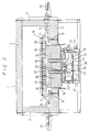
- a shaping apparatus for shaping a sheet of glass comprises a heating furnace 1 as a heating means for heating a sheet of glass G, a shaping mold 30 in the heating furnace 1, a lifting/lowering mechanism 20 (shown only in fig. 2) for vertically moving the shaping mold 30 in the heating furnace 1, a ring mold 10 for supporting at least the peripheral edge of the glass sheet G, a feed means including a chain 12 for feeding the ring mold 10 into and out of the heating furnace 1, and a quenching device 40 for quenching the shaped glass sheet G.
- the heating furnace 1 is constructed of three side walls 2, a furnace bed 7, a ceiling wall 3, and a vertically movable door 4. With the door 4 lifted, the ring mold 10 can be moved into and out of the heating furnace 1 by the chain 12.
- a number of heaters 5 are attached to the inner surfaces of the wall components of the heating furnace 1.
- a local area heating heater 6 is disposed in the heating furnace 1 above the shaping mold 30.
- FIG. 2 shows the heating furnace 1 with the ring mold 10 placed therein.
- a pair of spaced rails 8 is mounted on the furnace bed 7, and castors 11 rotatably supported on a lower portion of the ring mold 10 are positioned respectively on the rails 8 for rolling engagement therewith.
- the chain 12 (FIG. 1) is attached to the ring mold 30 and trained around sprockets, at least one of which is coupled to a motor (not shown). Therefore, the ring mold 10 can smoothly be taken into and out of the heating furnace 1 by energizing the motor.
- Two cylinder actuator units 13 (FIG. 2) are mounted on the outer surfaces of the two opposite side walls 2, and coupled to respective positioning pins 14. The positioning pins 14 are axially movable by the respective cylinder actuator units 13 into engagement with the ring mold 10 for thereby positioning the ring mold 10 in the heating furnace 1.
- the furnace bed 7 has a separate bed portion 7a which is vertically movable by the lifting/lowering mechanism 20.
- the shaping mold 30 is mounted on the separate bed portion 7a.
- the lifting/lowering mechanism 20 comprises a support frame 21, a pair of guides 22 and a guide 23 which are mounted on the support frame 21, and a motor 24 mounted on the support frame 21.
- Guide rods 25 extending downwardly from the lower surface of the separate bed 7a are slidably fitted in the guides 22, respectively.
- a rod 26 which is vertically movable by the motor 24 is slidably fitted in the guide 23.
- the rod 26 has an upper end fixed to an intermediate portion of an arm 27 pivotally coupled to the support frame 21.
- the arm 27 has an end joined to the lower surface of the separate bed 7a.
- the lifting/lowering mechanism 20 may comprise a cylinder actuator unit, rather than the illustrated assembly.
- the shaping mold 30 has upper and lower mold members 31, 32 with a space 33 defined therebetween.
- a pipe 34 extending through the separate bed 7a and connected to an evacuating unit (not shown), and another pipe 35 extending through the separate bed 7a and connected to a pressurized air source (not shown) open into the space 33.
- the upper mold member 31 is made of a ceramic material such as CaO-SiO2-Al2O3 or fused silica.
- the upper mold member 31 has an upper surface 36 which has been shaped by a numerically controlled machine in complementary relation to a final product shape.
- the upper shaping surface 36 is held in communication with the space 33 through small holes 37 defined in the upper mold member 31.
- the small holes 37 have a diameter of about 3 mm each, and are spaced about 60 mm on the upper shaping surface 36.
- a woven fabric or felt comprising alumina fibers, silica fibers, glass fibers, and metal fibers is attached to the upper shaping surface 36 except the open ends of the small holes 37, so that no glass sheet will adhere to the upper shaping surface 36.
- the lower mold member 32 is made of fused silica.
- the quenching device 40 is disposed near the heating furnace 1.
- the quenching device 40 is mounted on a mobile carriage 41 and has two upper and lower quenching air ejector nozzles 42 connected to a pressurized air source. As described later on, a shaped glass sheet G taken out of the heating furnace 1 is inserted and quenched between the nozzles 42.
- the peripheral edge of a flat glass sheet G is placed on the ring mold 10. Then, the door 4 of the heating furnace 1 is opened, and the chain 12 is driven to move the ring mold 10 into the heating furnace 1.
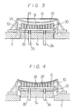
- the ring mold 10 is secured in position by the positioning pins 14. At this time, the glass sheet G is positioned directly above the shaping surface 36 of the shaping mold 30 as shown in FIG. 3.
- the heating furnace 1 is energized to start heating the glass sheet G, and the quenching device 40 is moved toward the heating furnace 1 in preparation for quenching a shaped glass sheet.
- the shaping mold 30 is lifted by the lifting/lowering mechanism 20 until the preliminarily shaped glass sheet G is received from the ring mold 10 onto the shaping surface 36 of the shaping mold 30 as shown in FIG. 4.
- the space 33 in the shaping mold 30 is evacuated to a vacuum ranging from - 20 mmAq. to - 300 mmAq. through the pipe 34.
- the glass sheet G is shaped primarily by the suction, it can accurately be curved or bent even where it should be bent deeply. While the glass sheet G is being heated and shaped, it is preferable to introduce hot air into the heating furnace 1 from an external source or circulate hot air in the heating furnace 1 with a fan disposed therein, so that various portions, especially the face and back, of the glass sheet G will be uniformly heated without any substantial temperature difference.
- the local area heating heater 6 disposed upwardly of the glass sheet G is also effective in heating and softening the glass sheet G efficiently and uniformly without substantial temperature differences on the glass sheet G.
- the shaping mold 30 is lowered by the lifting/lowering mechanism 20, and air is supplied into the space 33 in the shaping mold 30 through the pipe 35 to pressurize the space 33 up to + 100 mmAq. or less. Therefore, air is ejected out of the small holes 37 toward the glass sheet G, so that the glass sheet G will easily be separated from the shaping surface 36. Then, the shaping mold 30 is lowered to transfer the glass sheet G back onto the ring mold 10.
- the chain 12 is driven to move the ring mold 10 with the glass sheet G placed thereon out of the heating furnace 1 toward the quenching device 40 as shown in FIG. 5.
- the face and back of the shaped glass sheet G are then quenched by air ejected from the nozzles 42.
- the quenching device 40 is retracted to the right (FIG. 5), and the glass sheet G is fed to a next process either together with or independently of the ring mold 10.
- FIG. 6 shows a shaping apparatus for carrying out a shaping method according to another embodiment of the present invention.
- the shaping apparatus shown in FIG. 6 has a pair of opposite vertically movable doors 4, 4′ on the opposite sides of a heating furnace 1a.
- a glass sheet G to be shaped is fed into the heating furnace 1a through one of the doors 4′, and, after having been shaped, it is removed from the heating furnace 1a through the other door 4′.
- the shaped glass sheet G is then quenched by the quenching device 40 which has been brought in front of the door 4′ at least while the glass sheet G is being heated and shaped. Since the glass sheet G is delivered only in one direction through the heating furnace 1a toward the quenching device 40, a plurality of glass sheets G can successively be shaped and quenched.
- the heating furnace 1a shown in FIG. 6 can shape only one glass sheet G at a time.
- a long tunnel-shaped continuous heating furnace having inlet and outlet openings in its opposite ends e.g., a continuous heating furnace in which the heating temperature is gradually increased from the inlet opening toward a central region and gradually reduced from the central region toward the outlet opening, with the shaping mold 30 and the lifting/lowering mechanism 20 being located in the central region, may be employed in the present invention.
- the continuous heating furnace is more efficient since a plurality of glass sheets G can successively be introduced in a row into the heating furnace.
- Glass sheets G can be shaped more effectively by employing an auxiliary upper shaping mold in combination with the shaping mold 30 which is used as a lower shaping mold.
- the glass sheet since a glass sheet is bent under suction as well as by gravity, the glass sheet can efficiently be shaped even if it should be bent to a complex configuration, and glass sheets shaped by the method of the present invention do not suffer from substantial differences in shape. While a glass sheet is being shaped by the shaping mold, the peripheral edge of the glass sheet is separated from the ring mold. Consequently, inasmuch as the peripheral edge of the glass sheet is not pressed against the ring mold, no trace or mark of the ring mold is left on the glass sheet.
Description
- The present invention relates to a method of shaping a curved sheet of glass for use as an automotive windshield.
- Heretofore, there are known gravity and pressing processes for shaping sheets of glass to curved form.
- According to the gravity process, a sheet of glass is placed on a ring mold so that the peripheral edge of the glass sheet is softened with heat to the extent that it is deformed by gravity to a shape complementary to the shape of the ring mold. The pressing process employs a pair of upper and lower molds or a pair of lateral molds for bending a softened sheet of glass therebetween.
- The gravity process cannot bend a glass sheet to a considerably complex shape because only the peripheral edge of the glass sheet is held on the ring mold. Bent glass sheets formed by the gravity process tend to vary in configuration.
- The pressing process allows more uniformly shaped glass sheets. However, if a sheet must be highly softened, and pressed by the molds under stronger forces. This is disadvantageous in that the glass tends to stick to the molds and cannot easily be separated from the molds, and the shaped glass sheet may have strains.
- One variation of such a pressing process, using a single mold and a hot blast, is shown in DE-A1-3 640 892. In this arrangement, a preheated glass sheet is transported above a forming mold by a suction plate. The glass sheet is then released and drops onto the forming mold, the glass sheet being caused to take up the shape of the mold by means of a hot air blast. Such an arrangement can be satisfactory where a simple and relatively lightly curved result is required, but with more complex shapes, difficulties may arise due to the complexity of the finished glass object and the need, in many cases, for accuracy of finish.
- Thus, in this situation there is again a tendency for the glass to stick to the mold and/or for the glass to be undesirably stressed, and even to exhibit cracks, making it unsuitable for certain applications.
- In view of the foregoing problems of the conventional methods of shaping glass, it is an object of the present invention to provide a method of shaping a sheet of glass easily and efficiently to uniform shape such that glass sheets of complex shape can be produced without any substantial error or difference in shape.
- According to the present invention, there is provided a method of shaping a glass sheet, comprising the steps of supporting at least a peripheral edge of a glass sheet to be shaped on a ring mold, moving the ring mold into a heating furnace until the glass sheet is positioned directly above a shaping mold in the heating furnace, heating the glass sheet until the glass sheet on the ring mold is softened and deformed to a shape complimentary to the ring mold, lifting the shaping mold with respect to the ring mold to transfer the glass sheet from the ring mold onto the shaping mold and attracting the glass sheet against a shaping surface of the shaping mold to finally shape the glass sheet complementarily to the shaping surface, lowering the shaping mold with respect to the ring mold to transfer the shaped glass sheet from the shaping mold onto the ring mold and moving the ring mold out of the heating furnace.
- After the glass sheet has been shaped by the shaping mold, air may be ejected from the shaping surface of the shaping mold toward the glass sheet so that the glass sheet can easily be separated from the shaping surface.
- The invention will now be described in greater detail, by way of example, with reference to the drawings, in which :-
- FIG. 1 is a schematic elevational view, partly in cross section, of a shaping apparatus for carrying out a method of shaping glass according to a preferred embodiment of the present invention;
- FIG. 2 is an enlarged cross-sectional view taken along line II - II of FIG. 1, with a ring mold which supports a sheet of glass being placed in a heating furnace;
- FIG. 3 is a fragmentary cross-sectional view of the heating furnace in which the glass sheet supported on the ring mold is placed over a shaping mold;
- FIG. 4 is a fragmentary cross-sectional view of the heating furnace in which the glass sheet that has been transferred from the ring mold onto the shaping mold is being shaped by being attracted to a shaping surface of the shaping mold;
- FIG. 5 is a schematic elevational view, partly in cross section, of the shaping apparatus in which the shaped glass sheet is being quenched by a quenching device; and
- FIG. 6 is a schematic elevational view, partly in cross section, of a shaping apparatus for carrying out a method of shaping sheet glass in accordance with another embodiment of the present invention.
- As shown in FIG. 1, a shaping apparatus for shaping a sheet of glass comprises a
heating furnace 1 as a heating means for heating a sheet of glass G, a shapingmold 30 in theheating furnace 1, a lifting/lowering mechanism 20 (shown only in fig. 2) for vertically moving the shapingmold 30 in theheating furnace 1, aring mold 10 for supporting at least the peripheral edge of the glass sheet G, a feed means including achain 12 for feeding thering mold 10 into and out of theheating furnace 1, and aquenching device 40 for quenching the shaped glass sheet G. - The
heating furnace 1 is constructed of threeside walls 2, afurnace bed 7, aceiling wall 3, and a verticallymovable door 4. With thedoor 4 lifted, thering mold 10 can be moved into and out of theheating furnace 1 by thechain 12. A number ofheaters 5 are attached to the inner surfaces of the wall components of theheating furnace 1. A localarea heating heater 6 is disposed in theheating furnace 1 above the shapingmold 30. - FIG. 2 shows the
heating furnace 1 with thering mold 10 placed therein. A pair of spaced rails 8 is mounted on thefurnace bed 7, andcastors 11 rotatably supported on a lower portion of thering mold 10 are positioned respectively on the rails 8 for rolling engagement therewith. The chain 12 (FIG. 1) is attached to thering mold 30 and trained around sprockets, at least one of which is coupled to a motor (not shown). Therefore, thering mold 10 can smoothly be taken into and out of theheating furnace 1 by energizing the motor. Two cylinder actuator units 13 (FIG. 2) are mounted on the outer surfaces of the twoopposite side walls 2, and coupled torespective positioning pins 14. Thepositioning pins 14 are axially movable by the respectivecylinder actuator units 13 into engagement with thering mold 10 for thereby positioning thering mold 10 in theheating furnace 1. - The
furnace bed 7 has aseparate bed portion 7a which is vertically movable by the lifting/lowering mechanism 20. The shapingmold 30 is mounted on theseparate bed portion 7a. - The lifting/
lowering mechanism 20 comprises asupport frame 21, a pair ofguides 22 and aguide 23 which are mounted on thesupport frame 21, and amotor 24 mounted on thesupport frame 21.Guide rods 25 extending downwardly from the lower surface of theseparate bed 7a are slidably fitted in theguides 22, respectively. Arod 26 which is vertically movable by themotor 24 is slidably fitted in theguide 23. Therod 26 has an upper end fixed to an intermediate portion of anarm 27 pivotally coupled to thesupport frame 21. Thearm 27 has an end joined to the lower surface of theseparate bed 7a. When themotor 24 is energized, therod 26 is vertically moved to swing thearm 27 for thereby vertically moving theseparate bed 7a and the shapingmold 30. The lifting/lowering mechanism 20 may comprise a cylinder actuator unit, rather than the illustrated assembly. - The shaping
mold 30 has upper andlower mold members space 33 defined therebetween. Apipe 34 extending through theseparate bed 7a and connected to an evacuating unit (not shown), and anotherpipe 35 extending through theseparate bed 7a and connected to a pressurized air source (not shown) open into thespace 33. Theupper mold member 31 is made of a ceramic material such as CaO-SiO₂-Al₂O₃ or fused silica. Theupper mold member 31 has anupper surface 36 which has been shaped by a numerically controlled machine in complementary relation to a final product shape. The upper shapingsurface 36 is held in communication with thespace 33 throughsmall holes 37 defined in theupper mold member 31. Thesmall holes 37 have a diameter of about 3 mm each, and are spaced about 60 mm on the upper shapingsurface 36. A woven fabric or felt comprising alumina fibers, silica fibers, glass fibers, and metal fibers is attached to theupper shaping surface 36 except the open ends of thesmall holes 37, so that no glass sheet will adhere to theupper shaping surface 36. Thelower mold member 32 is made of fused silica. - As shown in FIG. 1, the
quenching device 40 is disposed near theheating furnace 1. Thequenching device 40 is mounted on amobile carriage 41 and has two upper and lower quenchingair ejector nozzles 42 connected to a pressurized air source. As described later on, a shaped glass sheet G taken out of theheating furnace 1 is inserted and quenched between thenozzles 42. - A process of shaping a glass sheet on the shaping apparatus thus constructed will be described below.
- As shown in FIG. 1, the peripheral edge of a flat glass sheet G is placed on the
ring mold 10. Then, thedoor 4 of theheating furnace 1 is opened, and thechain 12 is driven to move thering mold 10 into theheating furnace 1. When thering mold 10 has reached a predetermined position in theheating furnace 1, thering mold 10 is secured in position by thepositioning pins 14. At this time, the glass sheet G is positioned directly above the shapingsurface 36 of the shapingmold 30 as shown in FIG. 3. - Thereafter, the
heating furnace 1 is energized to start heating the glass sheet G, and thequenching device 40 is moved toward theheating furnace 1 in preparation for quenching a shaped glass sheet. When the glass sheet G is softened with heat and starts being deformed into a shape complementary to the shape of the ring mold 10 (preliminary shaping), the shapingmold 30 is lifted by the lifting/lowering mechanism 20 until the preliminarily shaped glass sheet G is received from thering mold 10 onto the shapingsurface 36 of the shapingmold 30 as shown in FIG. 4. At the same time that the shapingmold 30 is elevated, thespace 33 in the shapingmold 30 is evacuated to a vacuum ranging from - 20 mmAq. to - 300 mmAq. through thepipe 34. Air between the lower surface of the glass sheet G and the shapingsurface 36 of the shapingmold 30 is removed through thesmall holes 37 into thespace 33, thus attracting the glass sheet G against the shapingsurface 36 under suction. As a result, the glass sheet G placed on the shapingsurface 36 is finally shaped by the shapingsurface 36 as well as by gravity. According to the method of the present invention, the glass sheet G is shaped primarily by the suction, it can accurately be curved or bent even where it should be bent deeply. While the glass sheet G is being heated and shaped, it is preferable to introduce hot air into theheating furnace 1 from an external source or circulate hot air in theheating furnace 1 with a fan disposed therein, so that various portions, especially the face and back, of the glass sheet G will be uniformly heated without any substantial temperature difference. The localarea heating heater 6 disposed upwardly of the glass sheet G is also effective in heating and softening the glass sheet G efficiently and uniformly without substantial temperature differences on the glass sheet G. - After the glass sheet G has been shaped, the shaping
mold 30 is lowered by the lifting/loweringmechanism 20, and air is supplied into thespace 33 in the shapingmold 30 through thepipe 35 to pressurize thespace 33 up to + 100 mmAq. or less. Therefore, air is ejected out of thesmall holes 37 toward the glass sheet G, so that the glass sheet G will easily be separated from the shapingsurface 36. Then, the shapingmold 30 is lowered to transfer the glass sheet G back onto thering mold 10. - Subsequently, the
chain 12 is driven to move thering mold 10 with the glass sheet G placed thereon out of theheating furnace 1 toward the quenchingdevice 40 as shown in FIG. 5. The face and back of the shaped glass sheet G are then quenched by air ejected from thenozzles 42. - Thereafter, the quenching
device 40 is retracted to the right (FIG. 5), and the glass sheet G is fed to a next process either together with or independently of thering mold 10. - FIG. 6 shows a shaping apparatus for carrying out a shaping method according to another embodiment of the present invention. The shaping apparatus shown in FIG. 6 has a pair of opposite vertically
movable doors doors 4′, and, after having been shaped, it is removed from the heating furnace 1a through theother door 4′. The shaped glass sheet G is then quenched by the quenchingdevice 40 which has been brought in front of thedoor 4′ at least while the glass sheet G is being heated and shaped. Since the glass sheet G is delivered only in one direction through the heating furnace 1a toward the quenchingdevice 40, a plurality of glass sheets G can successively be shaped and quenched. - The heating furnace 1a shown in FIG. 6 can shape only one glass sheet G at a time. However, a long tunnel-shaped continuous heating furnace having inlet and outlet openings in its opposite ends, e.g., a continuous heating furnace in which the heating temperature is gradually increased from the inlet opening toward a central region and gradually reduced from the central region toward the outlet opening, with the shaping
mold 30 and the lifting/loweringmechanism 20 being located in the central region, may be employed in the present invention. The continuous heating furnace is more efficient since a plurality of glass sheets G can successively be introduced in a row into the heating furnace. - Glass sheets G can be shaped more effectively by employing an auxiliary upper shaping mold in combination with the shaping
mold 30 which is used as a lower shaping mold. - With the present invention, as described above, since a glass sheet is bent under suction as well as by gravity, the glass sheet can efficiently be shaped even if it should be bent to a complex configuration, and glass sheets shaped by the method of the present invention do not suffer from substantial differences in shape. While a glass sheet is being shaped by the shaping mold, the peripheral edge of the glass sheet is separated from the ring mold. Consequently, inasmuch as the peripheral edge of the glass sheet is not pressed against the ring mold, no trace or mark of the ring mold is left on the glass sheet.
- Although there have been described what are at present considered to be the preferred embodiments of the present invention, it will be understood that. the invention may be embodied in other specific forms without departing from the essential characteristics thereof. The present embodiments are therefore to be considered in all aspects as illustrative, and not restrictive. The scope of the invention is indicated by the appended claims rather than by the foregoing description.
Claims (7)
- A method of shaping a glass sheet (G), comprising the steps of:(a) supporting at least a peripheral edge of a glass sheet (G) to be shaped on a ring mold (10);(b) moving said ring mold (10) into a heating furnace (1) until the glass sheet (G) is positioned directly above a shaping mold (30) in said heating furnace (1);(c) heating the glass sheet (G) until the glass sheet (G) on the ring mold (10) is softened and deformed into a shape complementary to said ring mold (10) so as to gradually and preliminarily shape the glass sheet (G);(d) lifting said shaping mold (30) with respect to said ring mold (10) to transfer the glass sheet (G) from said ring mold (10) onto said shaping mold (30) and attracting the glass sheet (G) against a shaping surface (36) of said shaping mold (30) to finally shape the glass sheet (G) complementarily to said shaping surface (36);(e) lowering said shaping mold (30) with respect to said ring mold (10) to transfer the shaped glass sheet (G) from said shaping mold (30) onto said ring mold (10); and(f) moving said ring mold (10) out of said heating furnace (1).
- A method according to claim 1, wherein said step (d) comprises the step of discharging air from between the lower surface of the glass sheet (G) transferred on the shaping surface (36) of said shaping mold (30) and said shaping surface (36), through said shaping mold (30).
- A method according to claim 1 or 2, wherein said step (e) includes the step of ejecting air from said shaping surface (36) toward said glass sheet (G) to separate the shaped glass sheet (G) from said shaping surface (36).
- A method according to claim 1, 2 or 3, wherein said step (b) includes the step of positioning a quenching device (40) near an outlet of said heating furnace (1) from which the shaped glass sheet (G) is moved out of the heating furnace (1), and wherein said step (f) includes the step of quenching, with said quenching device (40), the shaped glass sheet (G) moved out of the heating surface (1).
- A method according to any one of claims 1 to 4, wherein at least said steps (c) and (d) include the step of circulating hot air in the heating furnace (1) to uniformize the temperatures of various portions of the glass sheet (G).
- A method according to any one of claims 1 to 4, wherein at least said steps (c) and (d) include the step of uniformly heating and softening the glass sheet (G) with a heater (6) disposed above the glass sheet (G) in said heating furnace (1).
- A method according to any one of claims 1 to 6, wherein said step (b) comprises the step of moving said glass sheet (G) into said heating furnace (1) through a first door (4) thereof, and said step (f) comprises the step of moving the shaped glass sheet (G) from said heating furnace (1) through a second door (4) opposite to said first door (4), said method further including the step of: positioning of the quenching device (40) for quenching the shaped glass sheet (G) moved out of said heating furnace, in front of said second door(4).
Applications Claiming Priority (2)
| Application Number | Priority Date | Filing Date | Title |
|---|---|---|---|
| JP63250454A JPH0297432A (en) | 1988-10-04 | 1988-10-04 | Method for molding plate glass |
| JP250454/88 | 1988-10-04 |
Publications (2)
| Publication Number | Publication Date |
|---|---|
| EP0363097A1 EP0363097A1 (en) | 1990-04-11 |
| EP0363097B1 true EP0363097B1 (en) | 1994-03-16 |
Family
ID=17208118
Family Applications (1)
| Application Number | Title | Priority Date | Filing Date |
|---|---|---|---|
| EP89309975A Expired - Lifetime EP0363097B1 (en) | 1988-10-04 | 1989-09-29 | Method of shaping sheet glass |
Country Status (5)
| Country | Link |
|---|---|
| EP (1) | EP0363097B1 (en) |
| JP (1) | JPH0297432A (en) |
| KR (1) | KR0119376B1 (en) |
| CA (1) | CA1324723C (en) |
| DE (1) | DE68913887T2 (en) |
Families Citing this family (8)
| Publication number | Priority date | Publication date | Assignee | Title |
|---|---|---|---|---|
| DE69608747T2 (en) * | 1995-09-07 | 2000-10-12 | Ford Motor Co | Process for heating, shaping and hardening a glass sheet |
| DE69608746T2 (en) * | 1995-09-07 | 2000-10-12 | Ford Motor Co | Process for heating a glass sheet |
| DE10105200A1 (en) * | 2001-02-06 | 2002-08-14 | Saint Gobain | Method and device for bending glass sheets in pairs |
| DE102004008595B4 (en) | 2004-02-21 | 2006-03-23 | Schott Ag | Method for producing shaped glass-ceramic parts and device for carrying out the method |
| KR100631480B1 (en) * | 2004-11-17 | 2006-10-09 | 김진동 | A curved surface system |
| FR2880343B1 (en) | 2004-12-31 | 2007-06-22 | Saint Gobain | PROCESS FOR BOMBING GLASS SHEETS BY SUCTION |
| KR101581088B1 (en) | 2013-11-26 | 2015-12-29 | 쌩-고벵 글래스 프랑스 | Apparatus and method for forming bent sheet glass |
| CN113329978A (en) * | 2019-02-08 | 2021-08-31 | Agc株式会社 | Method for forming glass plate |
Family Cites Families (3)
| Publication number | Priority date | Publication date | Assignee | Title |
|---|---|---|---|---|
| US4280828A (en) * | 1978-11-13 | 1981-07-28 | Ppg Industries, Inc. | Shaping glass sheets by drop forming with pressure assist |
| JPS61222933A (en) * | 1985-03-28 | 1986-10-03 | Nippon Sheet Glass Co Ltd | Method for forming glass article and apparatus therefor |
| DE3640892A1 (en) * | 1986-11-29 | 1988-06-09 | Ver Glaswerke Gmbh | METHOD AND DEVICE FOR BENDING A GLASS DISC |
-
1988
- 1988-10-04 JP JP63250454A patent/JPH0297432A/en active Pending
-
1989
- 1989-09-29 CA CA000615172A patent/CA1324723C/en not_active Expired - Fee Related
- 1989-09-29 DE DE68913887T patent/DE68913887T2/en not_active Expired - Lifetime
- 1989-09-29 EP EP89309975A patent/EP0363097B1/en not_active Expired - Lifetime
- 1989-10-04 KR KR1019890014271A patent/KR0119376B1/en not_active IP Right Cessation
Also Published As
| Publication number | Publication date |
|---|---|
| EP0363097A1 (en) | 1990-04-11 |
| CA1324723C (en) | 1993-11-30 |
| JPH0297432A (en) | 1990-04-10 |
| KR0119376B1 (en) | 1997-09-30 |
| DE68913887T2 (en) | 1994-06-30 |
| KR910007821A (en) | 1991-05-30 |
| DE68913887D1 (en) | 1994-04-21 |
Similar Documents
| Publication | Publication Date | Title |
|---|---|---|
| US4282026A (en) | Apparatus for bending and tempering glass | |
| US4437871A (en) | Apparatus and method for bending glass sheets | |
| US5858047A (en) | Method and apparatus of bending glass sheets | |
| CA1241197A (en) | Shaping glass sheets to complicated shapes | |
| CA1204936A (en) | Controlling overheating of vacuum mold used to shape glass sheets | |
| CA1120725A (en) | Apparatus for bending and tempering glass | |
| US4361432A (en) | Apparatus and method for removing a glass sheet from a carrier | |
| JPH03505082A (en) | Method and device for transporting glass sheets | |
| US4277276A (en) | Method and apparatus for shaping glass sheets using deformable vacuum mold | |
| US5330550A (en) | Installation for the bending of glazing | |
| US4437872A (en) | Apparatus for bending and tempering glass sheets | |
| JPH06115960A (en) | Device and method for forming glass sheet | |
| EP0363097B1 (en) | Method of shaping sheet glass | |
| GB2058743A (en) | Method and apparatus for shaping glass sheets | |
| JP2831036B2 (en) | Method and apparatus for bending sheet glass | |
| WO1993006052A1 (en) | Method for bending and tempering glass sheets | |
| US5022908A (en) | Apparatus for bending glass sheet | |
| CA1105707A (en) | Vacuum holder system and method for use in bending glass | |
| US4364765A (en) | Apparatus and method for handling heated glass sheets | |
| JPS5919890B2 (en) | Glass plate processing equipment | |
| KR960013570B1 (en) | Method and apparatus for bending and tempering glass-sheets | |
| EP1041045B1 (en) | Device for positioning a vitreous sheet in correspondence of a moulding station in plants for glass panel manufacturing and manufacturing plant thereof | |
| CA1150053A (en) | Shaping glass sheets using molds of different shapes |
Legal Events
| Date | Code | Title | Description |
|---|---|---|---|
| PUAI | Public reference made under article 153(3) epc to a published international application that has entered the european phase |
Free format text: ORIGINAL CODE: 0009012 |
|
| AK | Designated contracting states |
Kind code of ref document: A1 Designated state(s): BE DE ES FR GB IT |
|
| 17P | Request for examination filed |
Effective date: 19900615 |
|
| 17Q | First examination report despatched |
Effective date: 19911115 |
|
| GRAA | (expected) grant |
Free format text: ORIGINAL CODE: 0009210 |
|
| AK | Designated contracting states |
Kind code of ref document: B1 Designated state(s): BE DE ES FR GB IT |
|
| ITF | It: translation for a ep patent filed |
Owner name: SOCIETA' ITALIANA BREVETTI S.P.A. |
|
| PG25 | Lapsed in a contracting state [announced via postgrant information from national office to epo] |
Ref country code: BE Effective date: 19940316 Ref country code: ES Free format text: THE PATENT HAS BEEN ANNULLED BY A DECISION OF A NATIONAL AUTHORITY Effective date: 19940316 |
|
| ET | Fr: translation filed | ||
| REF | Corresponds to: |
Ref document number: 68913887 Country of ref document: DE Date of ref document: 19940421 |
|
| PLBE | No opposition filed within time limit |
Free format text: ORIGINAL CODE: 0009261 |
|
| STAA | Information on the status of an ep patent application or granted ep patent |
Free format text: STATUS: NO OPPOSITION FILED WITHIN TIME LIMIT |
|
| 26N | No opposition filed | ||
| REG | Reference to a national code |
Ref country code: GB Ref legal event code: IF02 |
|
| PGFP | Annual fee paid to national office [announced via postgrant information from national office to epo] |
Ref country code: FR Payment date: 20050823 Year of fee payment: 17 |
|
| PGFP | Annual fee paid to national office [announced via postgrant information from national office to epo] |
Ref country code: DE Payment date: 20050922 Year of fee payment: 17 |
|
| PGFP | Annual fee paid to national office [announced via postgrant information from national office to epo] |
Ref country code: GB Payment date: 20050928 Year of fee payment: 17 |
|
| PGFP | Annual fee paid to national office [announced via postgrant information from national office to epo] |
Ref country code: IT Payment date: 20060930 Year of fee payment: 18 |
|
| PG25 | Lapsed in a contracting state [announced via postgrant information from national office to epo] |
Ref country code: DE Free format text: LAPSE BECAUSE OF NON-PAYMENT OF DUE FEES Effective date: 20070403 |
|
| GBPC | Gb: european patent ceased through non-payment of renewal fee |
Effective date: 20060929 |
|
| REG | Reference to a national code |
Ref country code: FR Ref legal event code: ST Effective date: 20070531 |
|
| PG25 | Lapsed in a contracting state [announced via postgrant information from national office to epo] |
Ref country code: GB Free format text: LAPSE BECAUSE OF NON-PAYMENT OF DUE FEES Effective date: 20060929 |
|
| PG25 | Lapsed in a contracting state [announced via postgrant information from national office to epo] |
Ref country code: FR Free format text: LAPSE BECAUSE OF NON-PAYMENT OF DUE FEES Effective date: 20061002 |
|
| PG25 | Lapsed in a contracting state [announced via postgrant information from national office to epo] |
Ref country code: IT Free format text: LAPSE BECAUSE OF NON-PAYMENT OF DUE FEES Effective date: 20070929 |