EP0362982B1 - Réduction du gauchissement stéréolithographique - Google Patents
Réduction du gauchissement stéréolithographique Download PDFInfo
- Publication number
- EP0362982B1 EP0362982B1 EP89303778A EP89303778A EP0362982B1 EP 0362982 B1 EP0362982 B1 EP 0362982B1 EP 89303778 A EP89303778 A EP 89303778A EP 89303778 A EP89303778 A EP 89303778A EP 0362982 B1 EP0362982 B1 EP 0362982B1
- Authority
- EP
- European Patent Office
- Prior art keywords
- exposure
- layer
- lamina
- line
- pass
- Prior art date
- Legal status (The legal status is an assumption and is not a legal conclusion. Google has not performed a legal analysis and makes no representation as to the accuracy of the status listed.)
- Expired - Lifetime
Links
Images


Classifications
-
- B—PERFORMING OPERATIONS; TRANSPORTING
- B29—WORKING OF PLASTICS; WORKING OF SUBSTANCES IN A PLASTIC STATE IN GENERAL
- B29C—SHAPING OR JOINING OF PLASTICS; SHAPING OF MATERIAL IN A PLASTIC STATE, NOT OTHERWISE PROVIDED FOR; AFTER-TREATMENT OF THE SHAPED PRODUCTS, e.g. REPAIRING
- B29C35/00—Heating, cooling or curing, e.g. crosslinking or vulcanising; Apparatus therefor
- B29C35/02—Heating or curing, e.g. crosslinking or vulcanizing during moulding, e.g. in a mould
- B29C35/08—Heating or curing, e.g. crosslinking or vulcanizing during moulding, e.g. in a mould by wave energy or particle radiation
-
- G—PHYSICS
- G03—PHOTOGRAPHY; CINEMATOGRAPHY; ANALOGOUS TECHNIQUES USING WAVES OTHER THAN OPTICAL WAVES; ELECTROGRAPHY; HOLOGRAPHY
- G03F—PHOTOMECHANICAL PRODUCTION OF TEXTURED OR PATTERNED SURFACES, e.g. FOR PRINTING, FOR PROCESSING OF SEMICONDUCTOR DEVICES; MATERIALS THEREFOR; ORIGINALS THEREFOR; APPARATUS SPECIALLY ADAPTED THEREFOR
- G03F7/00—Photomechanical, e.g. photolithographic, production of textured or patterned surfaces, e.g. printing surfaces; Materials therefor, e.g. comprising photoresists; Apparatus specially adapted therefor
- G03F7/70—Microphotolithographic exposure; Apparatus therefor
- G03F7/70416—2.5D lithography
-
- B—PERFORMING OPERATIONS; TRANSPORTING
- B29—WORKING OF PLASTICS; WORKING OF SUBSTANCES IN A PLASTIC STATE IN GENERAL
- B29C—SHAPING OR JOINING OF PLASTICS; SHAPING OF MATERIAL IN A PLASTIC STATE, NOT OTHERWISE PROVIDED FOR; AFTER-TREATMENT OF THE SHAPED PRODUCTS, e.g. REPAIRING
- B29C64/00—Additive manufacturing, i.e. manufacturing of three-dimensional [3D] objects by additive deposition, additive agglomeration or additive layering, e.g. by 3D printing, stereolithography or selective laser sintering
- B29C64/10—Processes of additive manufacturing
- B29C64/106—Processes of additive manufacturing using only liquids or viscous materials, e.g. depositing a continuous bead of viscous material
- B29C64/124—Processes of additive manufacturing using only liquids or viscous materials, e.g. depositing a continuous bead of viscous material using layers of liquid which are selectively solidified
- B29C64/129—Processes of additive manufacturing using only liquids or viscous materials, e.g. depositing a continuous bead of viscous material using layers of liquid which are selectively solidified characterised by the energy source therefor, e.g. by global irradiation combined with a mask
- B29C64/135—Processes of additive manufacturing using only liquids or viscous materials, e.g. depositing a continuous bead of viscous material using layers of liquid which are selectively solidified characterised by the energy source therefor, e.g. by global irradiation combined with a mask the energy source being concentrated, e.g. scanning lasers or focused light sources
-
- B—PERFORMING OPERATIONS; TRANSPORTING
- B29—WORKING OF PLASTICS; WORKING OF SUBSTANCES IN A PLASTIC STATE IN GENERAL
- B29C—SHAPING OR JOINING OF PLASTICS; SHAPING OF MATERIAL IN A PLASTIC STATE, NOT OTHERWISE PROVIDED FOR; AFTER-TREATMENT OF THE SHAPED PRODUCTS, e.g. REPAIRING
- B29C64/00—Additive manufacturing, i.e. manufacturing of three-dimensional [3D] objects by additive deposition, additive agglomeration or additive layering, e.g. by 3D printing, stereolithography or selective laser sintering
- B29C64/40—Structures for supporting 3D objects during manufacture and intended to be sacrificed after completion thereof
-
- B—PERFORMING OPERATIONS; TRANSPORTING
- B33—ADDITIVE MANUFACTURING TECHNOLOGY
- B33Y—ADDITIVE MANUFACTURING, i.e. MANUFACTURING OF THREE-DIMENSIONAL [3-D] OBJECTS BY ADDITIVE DEPOSITION, ADDITIVE AGGLOMERATION OR ADDITIVE LAYERING, e.g. BY 3-D PRINTING, STEREOLITHOGRAPHY OR SELECTIVE LASER SINTERING
- B33Y10/00—Processes of additive manufacturing
-
- B—PERFORMING OPERATIONS; TRANSPORTING
- B33—ADDITIVE MANUFACTURING TECHNOLOGY
- B33Y—ADDITIVE MANUFACTURING, i.e. MANUFACTURING OF THREE-DIMENSIONAL [3-D] OBJECTS BY ADDITIVE DEPOSITION, ADDITIVE AGGLOMERATION OR ADDITIVE LAYERING, e.g. BY 3-D PRINTING, STEREOLITHOGRAPHY OR SELECTIVE LASER SINTERING
- B33Y30/00—Apparatus for additive manufacturing; Details thereof or accessories therefor
-
- B—PERFORMING OPERATIONS; TRANSPORTING
- B33—ADDITIVE MANUFACTURING TECHNOLOGY
- B33Y—ADDITIVE MANUFACTURING, i.e. MANUFACTURING OF THREE-DIMENSIONAL [3-D] OBJECTS BY ADDITIVE DEPOSITION, ADDITIVE AGGLOMERATION OR ADDITIVE LAYERING, e.g. BY 3-D PRINTING, STEREOLITHOGRAPHY OR SELECTIVE LASER SINTERING
- B33Y40/00—Auxiliary operations or equipment, e.g. for material handling
- B33Y40/20—Post-treatment, e.g. curing, coating or polishing
-
- B—PERFORMING OPERATIONS; TRANSPORTING
- B33—ADDITIVE MANUFACTURING TECHNOLOGY
- B33Y—ADDITIVE MANUFACTURING, i.e. MANUFACTURING OF THREE-DIMENSIONAL [3-D] OBJECTS BY ADDITIVE DEPOSITION, ADDITIVE AGGLOMERATION OR ADDITIVE LAYERING, e.g. BY 3-D PRINTING, STEREOLITHOGRAPHY OR SELECTIVE LASER SINTERING
- B33Y50/00—Data acquisition or data processing for additive manufacturing
-
- B—PERFORMING OPERATIONS; TRANSPORTING
- B44—DECORATIVE ARTS
- B44B—MACHINES, APPARATUS OR TOOLS FOR ARTISTIC WORK, e.g. FOR SCULPTURING, GUILLOCHING, CARVING, BRANDING, INLAYING
- B44B1/00—Artist's machines or apparatus equipped with tools or work holders moving or able to be controlled three-dimensionally for making single sculptures or models
- B44B1/006—Artist's machines or apparatus equipped with tools or work holders moving or able to be controlled three-dimensionally for making single sculptures or models using computer control means
-
- G—PHYSICS
- G03—PHOTOGRAPHY; CINEMATOGRAPHY; ANALOGOUS TECHNIQUES USING WAVES OTHER THAN OPTICAL WAVES; ELECTROGRAPHY; HOLOGRAPHY
- G03F—PHOTOMECHANICAL PRODUCTION OF TEXTURED OR PATTERNED SURFACES, e.g. FOR PRINTING, FOR PROCESSING OF SEMICONDUCTOR DEVICES; MATERIALS THEREFOR; ORIGINALS THEREFOR; APPARATUS SPECIALLY ADAPTED THEREFOR
- G03F7/00—Photomechanical, e.g. photolithographic, production of textured or patterned surfaces, e.g. printing surfaces; Materials therefor, e.g. comprising photoresists; Apparatus specially adapted therefor
- G03F7/0037—Production of three-dimensional images
Definitions
- This invention relates to a process and an apparatus for the formation of a three-dimensional object according to the precharacterising part of claim 1, claim 22, claim 42 and claim 44 respectively.
- the present invention is particularly concerned with eliminating or reducing a form of distortion called "curl" which is liable to arise in stereolithography and the nature of which is explained hereafter.
- EP-A-0 354 637 (3D Systems, Inc.) published 14th February, 1990 which, inter alia, describes data processing techniques for converting CAD (computer aided design) data to data controlling stereolithographic processing;
- EP-A-0 355 945 (3D Systems, Inc.) published 28th February, 1990, which describes techniques for relieving stress
- EP-A-0 338 751 (3D Systems, Inc.) published 25th October, 1989 which describes supports for the building of three-dimensional objects
- plastic parts and the like It is common practice in the production of plastic parts and the like to first design such a part and then painstakingly produce a prototype of the part, all involving considerable time, effort and expense. The design is then reviewed and, oftentimes, the laborious process is again and again repeated until the design has been optimized. After design optimization, the next step is production. Most production plastic parts are injection molded. Since the design time and tooling costs are very high, plastic parts are usually only practical in high volume production. While other processes are available for the production of plastic parts, including direct machine work, vacuum-forming and direct forming, such methods are typically only cost effective for short run production, and the parts produced are usually inferior in quality to molded parts.
- stereolithography is a method for automatically building complex plastic parts by successively printing cross-sections of photopolymer (such as liquid plastic) on top of each other until all of the thin layers are joined together to form a whole part.
- photopolymer such as liquid plastic
- Photocurable polymers change from liquid to solid in the presence of light and their photospeed with ultraviolet light (UV) is fast enough to make them practical model building materials.
- the material that is not polymerized when a part is made is still usable and remains in the vat as successive parts are made.
- An ultraviolet laser generates a small intense spot of UV. This spot is moved across the liquid surface with a galvanometer mirror X-Y scanner. The scanner is driven by computer generated vectors or the like. Precise complex patterns can be rapidly produced with this technique.
- SLA stereolithography apparatus
- Stereolithography represents an unprecedented way to quickly make complex or simple parts without tooling. Since this technology depends on using a computer to generate its cross sectional patterns, there is a natural data link to CAD/CAM. However, such systems have encountered difficulties relating to shrinkage, stress, curl and other distortions, as well as resolution, accuracy and difficulties in producing certain object shapes.
- Objects made using stereolithography tend to distort when the materials used change density between the liquid state and the solid state. Density change causes material shrinkage or expansion, and this generates stress as a part is formed in a way to "curl" lower layers or adjacent structure, giving an overall distortion. Materials with less density change exhibit less curl, but many materials that are otherwise useful for stereolithography have high shrinkage. The "curl” effect limits the accuracy of the object formation by stereolithography. This invention provides ways to eliminate or reduce the "curl” effect.
- the shrinkage in photopolymers is due to the shrinkage in the formation of the acrylic bonds.
- Photopolymers can be made by reacting other functional groups than acrylics, but they have substantially less reactivity than the acrylic bonded materials, resulting in generally inadequate speeds of solid material formation.
- Materials that are somewhat flexible when formed usually produce objects with less distortion, since they cannot transmit strain long distances through the object. However, this property is a disadvantage if the goal is to make stiff objects. Some materials are soft when formed, and then harden when post cured with higher levels of radiation or other means. These are useful materials for stereolithography. The whole subject of materials that produce less distortion, because of the way they make the transition from liquid to solid, is currently being studied. However, materials do not currently exist which produce distortion free parts.
- this invention is concerned with reducing or eliminating the effect of "curl” distortion in stereolithography.
- Curl is used to describe an effect similar to that found when applying coatings to such things as paper.
- a sheet is coated with a substance that shrinks, it curls up toward the coating. This is because the coating both shrinks and sticks to the sheet, and exerts a pulling force on the top but not on the bottom of the sheet.
- a sheet of paper has insufficient restraining force to resist the pulling, and most coatings will curl paper. The same thing happens when a photopolymer is cured on top of a thin sheet of already cured photo-polymer.
- U.S. patent 4,575,330 and EP-A-0 250 121 disclose a process and apparatus of the kind referred to in the introductory paragraph of this description. More particularly these specifications disclose apparatus comprising a source of prescribed stimulation, means for providing successive layers of transformable fluid medium in preparation for forming successive lamina of the object and means for selectively exposing each of said layers to prescribed stimulation to form successive lamina wherein said means for selectively exposing each of said layers is controlled by a control device operable according to a prescribed program.
- EP-A-0 250 121 discloses a process in which each fresh layer of transformable fluid medium is fully exposed through the thickness of the layer to cure it and adhere it to the preceding layer.
- EP-A-0 250 121 recognizes that distortions may arise due to shrinkage and proposes to divide the layer pattern into two complementary checkerboard patterns which are fully cured throughout in respective exposure steps whereby the two checkerboard patterns unite to form the desired pattern for the layer. If necessary a further overall exposure can be made to ensure such unity in the final lamina.
- a process ⁇ of the kind referred to is characterized by:
- apparatus of the kind defined above is characterized by:
- the implementation of the present invention will be described in conjunction with the principles of computer generated graphics in combination with stereolithography, i.e., the application of lithographic techniques to the production of three-dimensional objects, to simultaneously execute computer aided design (CAD) and computer aided manufacturing (CAM) in producing three-dimensional objects directly from computer instructions.
- CAD computer aided design
- CAM computer aided manufacturing
- the invention can be applied for the purposes of sculpturing models and prototypes in a design phase of product development, or as a manufacturing system, or even as a pure art form.
- the data base of a CAD system can take several forms.
- One form consists of representing the surface of an object as a mesh of triangles. These triangles completely form the inner and outer surfaces of the object.
- This CAD representation commonly also includes a unit length normal vector for each triangle. the normal points away from the solid which the triangle is bounding.
- a programmed movable spot beam of UV light shining on a surface or layer of UV curable liquid is used to form a solid cross-section of the object at the surface of the liquid.
- the object is then moved, in a programmed manner, away from the liquid surface by the thickness of one layer, and the next cross-section is then formed and adhered to the immediately preceding layer defining the object. This process is continued until the entire object is formed.
- synergistic stimulation for a curable fluid medium such as particle bombardment (electron beams and the like), chemical reactions by spraying materials through a mask or by ink jets, or impinging radiation other than ultraviolet light, may be used in the practice of the invention.
- particle bombardment electron beams and the like
- chemical reactions by spraying materials through a mask or by ink jets, or impinging radiation other than ultraviolet light, may be used in the practice of the invention.
- Stereolithography may use a moving laser beam to build parts by solidifying successive layers of liquid plastic. This method enables a designer to create a design on a CAD system and build an accurate plastic model in a few hours.
- the solid model is first designed in the normal way on the CAD system, without specific reference to the stereolithographic process. A copy of the model is made for stereolithographic processing.
- objects can be designed with structural configurations that reduce stress and curl in the ultimately formed object.
- a/k/a also known as the "dashed line” technique
- the pulling force normally transmitted along the vector is eliminated, and the curl effect is reduced.
- a stereolithography line which is part of a vertical or horizontal formation is drawn with bends in the line instead of a straight line
- a/k/a the "bent-line” technique the pulling force normally transmitted along the vector is reduced, and the curl effect is reduced.
- a stereolithography line which is part of a vertical or horizontal formation is drawn so that it does not adhere directly to the line below or beside it, but is attached, after it is formed with a secondary structure, a/k/a the "secondary structure” technique, the pulling force down the vector is eliminated, the bending moment on adjacent lines is reduced, and the curl effect is greatly reduced.
- a stereolithography line which is part of a vertical or horizontal formation is drawn so that it does not adhere directly to the line below or beside it until the material is substantially reacted, a/k/a the "multi-pass” technique, the pulling force down the vector is reduced, the structure is more rigid so it can resist deformation, and the curl effect is greatly reduced.
- Model preparation for stereolithography involves selecting the optimum orientation, adding supports, and selecting the operating parameters of the stereolithography system.
- the optimum orientation will (1) enable the object to drain, (2) have the least number of unsupported surfaces, (3) optimize important surfaces, and (4) enable the object to fit in the resin vat. Supports must be added to secure unattached sections and for other purposes; a CAD library of supports can be prepared for this purpose.
- the stereolithography operating parameters include selection of the model scale and layer (slice) thickness.
- the surface of the solid model is then divided into triangles, typically "PHIGS".
- a triangle is the least complex polygon for vector calculations. The more triangles formed, the better the surface resolution and hence the more accurate the formed object with respect to the CAD design
- Data points representing the triangle coordinates are then transmitted to the stereolithographic system via appropriate network communications.
- the software of the stereolithographic system then slices the triangular sections horizontally (X-Y plane) at the selected layer thickness.
- the stereolithographic unit next calculates the section boundary, hatch, and horizontal surface (skin) vectors.
- Hatch vectors consist of cross-hatching between the boundary vectors.
- Skin vectors which are traced at high speed and with a large overlap, form the outside horizontal surfaces of the object.
- Interior horizontal areas, those within top and bottom skins, are not filled in other than by cross-hatch vectors.
- the SLA then forms the object one horizontal layer at a time by moving the ultraviolet beam of a helium-cadmium laser across the surface of a photocurable resin and solidifying the liquid where it strikes. Absorption in the resin prevents the laser light from penetrating deeply and allows a thin layer to be formed.
- Each layer is comprised of vectors which are drawn in the following order: border, hatch, and surface.
- the first layer that is drawn by the SLA adheres to a horizontal platform located just below the liquid surface.
- This platform is attached to an elevator which then lowers its vertically under computer control.
- the platform dips several millimeters into the liquid to coat the previously cured layer with fresh liquid, then rises up a smaller distance leaving a thin film of liquid from which the second layer will be formed.
- the next layer is drawn. Since the resin has adhesive properties, the second layer becomes firmly attached to the first. This process is repeated until all the layers have been drawn and the entire three-dimensional object is formed. Normally, the bottom 0.25 inch or so of the object is a support structure on which the desired part is built. Resin that has not been exposed to light remains in the vat to be used for the next part. There is very little waste of material.
- Post processing involves heating the formed object to remove excess resin, ultraviolet or heat curing to complete polymerization, and removing supports. Additional processing, including sanding and assembly into working models, may also be performed.
- Stereolithography has many advantages for producing plastic objects. It avoids the need of producing design layouts and drawings, and of producing tooling drawings and tooling.
- the designer can work directly with the computer and a stereo-lithographic device, and when he is satisfied with the design as displayed on the output screen of the computer, he can fabricate a part for direct examination. If the design has to be modified, it can be easily done through the computer, and then another part can be made to verify that the change was correct. If the design calls for several parts with interacting design parameters, stereolithography becomes even more useful because of all of the part designs can be quickly changed and made again so that the total assembly can be made and examined, repeatedly if necessary.
- part production can begin immediately, so that the weeks and months between design and production are avoided. Ultimate production rates and parts costs should be similar to current injection molding costs for short run production, with even lower labor costs than those associated with injection molding. Injection molding is economical only when large numbers of identical parts are required. Stereolithography is useful for short run production because the need for tooling is eliminated and production set-up time is minimal. Likewise, design changes and custom parts are easily provided using the technique. Because of the ease of making parts, stereolithography can allow plastic parts to be used in many places where metal or other material parts are now used. Moreover, it allows plastic models of objects to be quickly and economically provided, prior to the decision to make more expensive metal or other material parts.
- the present invention will be described as applied to a stereolithographic method and apparatus of the type for building up successive layers of photopolymer, where each layer is formed by drawing a series of vectors with a light pencil on the liquid surface that defines each cross-section of the object, wherein the improvement comprises reducing or eliminating curl.
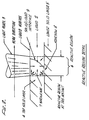
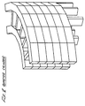
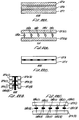
- a number of techniques have been examined by building rails that are a series of layers of straight lines, and examining the resulting distortion. The force, or stress, in this case is generated at the interface where the photopolymer cures (and shrinks) and adheres to the layer below, as shown in the following diagram.
- light pencil 3 moves across liquid 2 in the direction shown, converting it to solid 1. This forms a solid top layer 4, that adheres to lower layer 5.
- the term light pencil refers to synergistic stimulation such as UV light which impinges on the surface of the liquid photopolymer.
- FIG. 2 In the expanded diagram (FIG. 2), the light from the pencil is shown penetrating into the photopolymer, forming reactive region 6. Solid/liquid interface 9, or gel point, is indicated. However, the polymeric state of the material in the active region is more complex. All of the material in the region is reacting. The material at the upper left of the region is most reacted, because the light is most intense and the pencil has been in this area the most time. The material at the lower right, just above the lower layer, is the least reacted, because the light is the least intense and the pencil has been in this area the least time.
- Reactive region 6 acts as a complex shrinking cylinder, and shrinkage 7 is toward the interior of this cylinder.
- shrinkage 7 is toward the interior of this cylinder.
- the new solid material of top layer 4 attaches to the lower layer 5 with adhesion 8.
- the first mechanism is that the polymer shrinks due to polymer bond formation.
- the result is that the solid polymer state is more dense than the liquid pre-polymer state, and hence a given amount of polymer takes up less volume than the pre-polymer that it was formed from.
- This shrinkage mechanism is essentially instantaneous compared to the time taken to generate laser patterns (i.e., less than a microsecond).
- the second mechanism is a thermal effect. Photopolymers are exothermic, so they give off heat when they react. This heat raises the temperature of the polymer, and it expands upon formation.
- the subsequent cooling and shrinkage has the same effect as the shrinkage due to the change of state, except it is slower, and is long compared to the time taken to generate laser patterns (seconds).
- the change of state mechanism is the larger of the two types of shrinkage.
- a typical example of a stereolithographic photopolymer is DeSoto SLR800 stereolithography resin, made by DeSoto, Inc., 1700 South Mt. Prospect Road, Des Plaines, Illinois 60018.
- the methods to control curl depend on building parts in ways so that the effects (a) and (b) above are eliminated or reduced.
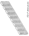
- ways to draw rails with reduced curl There are several simple examples of ways to draw rails with reduced curl; 1) a dashed line, to provide isolation of the pulling effect, 2) a line with short segments at angles to each other, to isolate the pulling effect, 3) lines that do not adhere to the layer below, to eliminate the pulling effect, but which are held together with other structure, and 4) lines that are as fully reacted as possible before the exposure that extends the gel point (and adhesion) to the lower layer is applied.
- These techniques are referred to respectively as the dashed line, bent line, secondary structure, and multi-pass techniques.
- FIG. 3 A rail made with a dashed line is illustrated in FIG. 3.
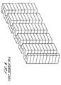
- FIG. 4 shows a rail made with short segments at angles to each other.
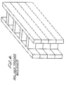
- FIGS. 5a and 5b illustrates a rail made with lines that do not adhere to the layer below but which are held together with other structure.
- reaction time taken, to form a layer in stereolithography depends on the layer thickness, the adsorption rate of the incident reactant energy, and the reactant rate of the material.
- the thickness response curve to form a solid film on a liquid surface with incident reactant energy is a logarithmic function.
- the solid material at the liquid/solid interface is just at the gel point, and the solid material at the surface is the most reacted. After a film is formed, subsequent exposures increase the reaction at the surface, but extend the thickness of the film less and less.
- An effective way to control curl is to choose a layer thickness that is large enough so that the bulk of the new top layer is highly cured (reacted). It is even more effective to cure this layer with multiple exposures so that only the last few exposures achieve the adhesion. In this case, most of the material in the reactive region has already changed density before adhesion occurs. Also, the new top layer and the lower layers are more fully cured and more able to resist deformation.
- a rail is built with two parallel walls close to each other, with exposure small enough so the layers do not adhere, and the walls are connected with short perpendicular vectors that are exposed to a depth great enough so that the layers adhere at these points and hold the structure together.
- the vectors for the two walls are both grown for each layer, and the adhesion is achieved by using additional exposure for the connecting vectors.
- the amount of curl of the part depends on the amount of exposure beyond that required to make the polymer depth equal to the layer depth. That is, the more the walls are exposed beyond the point where the layer touches the layer below, the more the part curls.
- This is, in fact, the basis of a standard "curl test" for different resins described in more detail further on in this application. According to this test, a series of these quarter cylinders are built at different exposures, and the curl versus exposure is plotted. Using this test, it has been discovered that different resin formulas curl differently, and this allows the selection of the best resins.
- the methods described herein to reduce curl are also applicable to the technique of building parts by fusing metal or plastic powder with a heat generating laser.
- the powder fusing technique may be even more susceptible to curl than by building with photopolymers, and the curl reduction techniques are needed even more with this method.
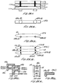
- FIG. 8 of the drawings illustrates an overall stereolithography system suitable for this purpose which is described in more detail in EP-A-0 354 637.
- the broken lines or bent lines can be "filled” with lower exposure dashed lines to even out the surface structure.
- Dashed or broken lines can be used as the support lines that do not adhere directly to the line below or next to them
- the unsupported lines are connected to the support lines with small additional structure lines.
- the secondary structure to attach unsupported lines can be "rivets" of higher exposure on top of these lines to connect them to the lines below.
- Thinner layers can be formed by adjusting the absorption of the material so that a given exposure produces a thinner film, while the material near the top surface is still almost fully reacted.
- a CAD generator 2 and appropriate interface 3 provide a data description of the object to be formed, typically in PHIGS format, via network communication such as ETHERNET or the like to an interface computer 4 where the object data is manipulated to optimize the data and provide output vectors which reduce stress, curl and distortion, and increase resolution, strength, accuracy, speed and economy of reproduction, even for rather difficult and complex object shapes.
- the interface computer 4 generates layer vector data by successively slicing, varying layer thickness, rounding polygon vertices, filling, generating flat skins, near-flat skins, up-facing and down-facing skins, scaling, cross-hatching, offsetting vectors and ordering of vectors.
- the vector data and parameters from the computer 4 are directed to a controller subsystem 5 for operating the system stereolithography laser, mirrors, elevator and the like.
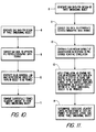
- FIGS. 10 and 11 are flow charts illustrating the basic system for generating three-dimensional objects by means of stereolithography.
- UV curable chemicals are known which can be induced to change to solid state polymer plastic by irradiation with ultraviolet light (UV) or other forms of synergistic stimulation such as electron beams, visible or invisible light, reactive chemicals applied by ink jet or via a suitable mask.
- UV curable chemicals are currently used as ink for high speed printing, in processes of coating of paper and other materials, as adhesives, and in other specialty areas.
- Lithography is the art of reproducing graphic objects, using various techniques. Modern examples include photographic reproduction, xerography, and microlithography, as is used in the production of microelectronic circuit boards. Computer generated graphics displayed on a plotter or a cathode ray tube are also forms of lithography, where the image is a picture of a computer coded object.
- Computer aided design (CAD) and computer aided manufacturing (CAM) are techniques that apply the capabilities of computers to the processes of designing and manufacturing.
- a typical example of CAD is in the area of electronic printed circuit design, where a computer and plotter draw the design of a printed circuit board, given the design parameters as computer data input.
- a typical example of CAM is a numerically controlled milling machine, where a computer and a milling machine produce metal parts, given the proper programming instructions. Both CAD and CAM are important and are rapidly growing technologies.
- Step 8 calls for generation of CAD or other data, typically in digital form, representing a three-imensional object to be formed by the system.
- This CAD data usually defines surfaces in polygon format, triangles and normals perpendicular to the planes of those triangles, e.g., for slope indications, being presently preferred, and in a presently preferred embodiment of the invention conforms to the Programmer's Hierarchial Interactive Graphics System (PHIGS) now adapted as an ANSI standard.
- PHIGS Hierarchial Interactive Graphics System
- Step 9 the PHIGS data or its equivalent is converted, to a modified data base for driving the stereolithography output system in forming three-imensional objects.
- information defining the object is specially processed to reduce stress, curl and distortion, and increase resolution, strength and accuracy of reproduction.
- Step 10 in FIG. 10 calls for the generation of individual solid laminae representing cross-sections of a three-dimensional object to be formed.
- Step 11 combines the successively formed adjacent lamine to form the desired three-dimensional object which has been programmed into the system for selective curing.
- the stereolithographic system generates three-dimensional objects by creating a cross-sectional pattern of the object to be formed at a selected surface of a fluid medium, e.g., a UV curable liquid or the like, capable of altering its physical state in response to appropriate synergistic stimulation such as impinging radiation, electron beam or other particle bombardment, or applied chemicals (as by ink jet or spraying over a mask adjacent the fluid surface), successive adjacent laminae, representing corresponding successive adjacent cross-sections of the object, being automatically formed and integrated together to provide a step-wise laminar or thin layer buildup of the object, whereby a three-dimensional object is formed and drawn from a substantially planar or sheet-like surface of the fluid medium during the forming process.
- a fluid medium e.g., a UV curable liquid or the like
- Step 8 calls for generation of CAD or other data, typically in digital form, representing a three-dimensional object to be formed by the system.
- the PHIGS data is converted by a unique conversion system to a modified data base for driving the stereolithography output system in forming three-dimensional objects.
- Step 12 calls for containing a fluid medium capable of solidification in response to prescribed reactive stimulation.
- Step 13 calls for application of that stimulation as a graphic pattern, in response to data output from the computer 4 in FIG. 9, at a designated fluid surface to form thin, solid, individual layers at that surface, each layer representing an adjacent cross-section of a three-dimensional object to be produced.
- each lamina will be a thin lamina, but thick enough to be adequately cohesive in forming the cross-section and adhering to the adjacent laminae defining other cross-sections of the object being formed.
- Step 14 in FIG. 13 calls for superimposing successive adjacent layers or laminae on each other as they are formed, to integrate the various layers and define the desired three-dimensional object. Normally as the fluid medium cures and solid material forms to define one lamina, that lamina is moved away from the working surface of the fluid medium and the next lamina is formed in the new liquid which replaces the previously formed lamina, so that each successive lamina is superimposed and integral with (by virtue of the natural adhesive properties of the cured fluid medium) all of the other cross-sectional laminae.
- FIGS. 12-13 of the drawings illustrate various apparatus suitable for implementing the stereolithographic methods illustrated and described by the systems and flow charts of FIGS. 1 - 3.
- Stepolithography is a method and apparatus for making solid objects by successively “printing” thin layers of a curable material, e.g., a UV curable material, one on top of the other.
- a curable material e.g., a UV curable material
- a programmable movable spot beam of UV light shining on a surface or layer of UV curable liquid is used to form a solid cross-section of the object at the surface of the liquid.
- the object is then moved, in a programmed manner, away from the liquid surface by the thickness of one layer and the next cross-section is then formed and adhered to the immediately preceding layer defining the object. This process is continued until the entire object is formed.
- the data base of a CAD system can take several forms.
- One form as previously indicated, consists of representing the surface of an object as a mesh of triangles (PHIGS). These triangles completely form the inner and outer surfaces of the object.
- This CAD representation also includes a unit length normal vector for each triangle. The normal points away from the solid which the triangle is bounding.
- This invention provides a means of processing such CAD data into the layer-by-layer vector data that is necessary for forming objects through stereolithography.
- plastic from one layer must overlay plastic that was formed when the previous layer was built.
- plastic that is formed on one layer will fall exactly on previously formed plastic from the preceding layer, and thereby provide good adhesion.
- a point will eventually be reached where the plastic formed on one layer does not make contact with the plastic formed on the previous layer, and this causes severe adhesion problems.
- Horizontal surfaces themselves do not present adhesion problems because by being horizontal, the whole section is built on one layer with side-to-side adhesion maintaining structural integrity.
- FIG. 12 An embodiment of a stereolithographic system to which the present invention is applicable is shown in elevational cross-section in FIG. 12.
- a container 21 is filled with a UV curable liquid 22 or the like, to provide a designated working surface 23.
- a programmable source of ultraviolet light 26 or the like produces a spot of ultraviolet light 27 in the plane of surface 23.
- the spot 27 is movable across the surface 23 by the motion of mirrors or other optical or mechanical elements (not shown in FIG. 12) used with the light source 26.
- the position of the spot 27 on surface 23 is controlled by a computer control system 28.
- the system 28 may be under control of CAD data produced by a generator 20 in a CAD design system or the like and directed in PHIGS format or its equivalent to a computerized conversion system 25. It is in this conversion system 25 that information defining the object is specially processed to reduce stress, curl and distortion, and increase resolution, strength and accuracy of reproduction.
- a movable elevator platform 29 inside container 21 can be moved up and down selectively, the position of the platform being controlled by the system 28. As the device operates, it produces a three-dimensional object 30 by step-wise buildup of integrated laminae such as 30a, 30b, 30c.
- the surface of the UV curable liquid 22 is maintained at a constant level in the container 21, and the spot of UV light 27, or other suitable form of reactive stimulation, of sufficient intensity to cure the liquid and convert it to a solid material, is moved across the working surface 23 in a programmed manner.
- the elevator platform 29 that was initially just below surface 23 is moved down from the surface in a programmed manner by any suitable actuator. In this way, the solid material that was initially formed is taken below surface 23 and new liquid 22 flows across the surface 23. A portion of this new liquid is, in turn, converted to solid material by the programmed UV light spot 27, and the new material adhesively connects to the material below it. This process is continued until the entire three-dimensional object 30 is formed.
- the object 30 is then removed from the container 21, and the apparatus is ready to produce another object. Another object can then be produced, or some new object can be made by changing the program in the computer 28.
- the curable liquid 22, e.g., UV curable liquid, must have several important properties: (A) It must cure fast enough with the available UV light source to allow practical object formation times. (B) It must be adhesive, so that successive layers will adhere to each other. (C) Its viscosity must be low enough so that fresh liquid material will quickly flow across the surface when the elevator moves the object. (D) It should absorb UV light so that the film formed will be reasonably thin. (E) It must be reasonably insoluble in that same solvent in the solid state, so that the object can be washed free of the UV cure liquid and partially cured liquid after the object has been formed. (F) It should be as non-toxic and non-irritating as possible.
- the cured material must also have desirable properties once it is in the solid state. These properties depend on the application involved, as in the conventional use of other plastic materials. Such parameters as color, texture, strength, electrical properties, flammability, and flexibility are among the properties to be considered. In addition, the cost of the material will be important in many cases.
- the UV curable material used in the present embodiment of a working stereolithography system is DeSoto SLR 800 stereolithography resin, made by DeSoto, Inc. of Des Plains, Illinois.
- the light source 26 produces the spot 27 of UV light small enough to allow the desired object detail to be formed, and intense enough to cure the UV curable liquid being used quickly enough to be practical.
- the source 26 is arranged so it can be programmed to be turned off and on, and to move, such that the focused spot 27 moves across the surface 23 of the liquid 22.
- the spot 27 moves, it cures the liquid 22 into a solid, and "draws" a solid pattern on the surface in much the same way a chart recorder or plotter uses a pen to draw a pattern on paper.
- the light source 26 is typically a helium-cadmium ultraviolet laser such as the Model 4240-N HeCd Multimode Laser, made by Liconix of Sunnyvale, California.
- means may be provided to keep the surface 23 at a constant level and to replenish this material after an object has been removed, so that the focus spot 27 will remain sharply in focus on a fixed focus plane, thus insuring maximum resolution in forming a high layer along the working surface.
- the elevator platform 29 is used to support and hold the object 30 being formed, and to move it up and down as required. Typically, after a layer is formed, the object 30 is moved beyond the level of the next layer to allow the liquid 22 to flow into the momentary void at surface 23 left where the solid was formed, and then it is moved back to the correct level for the next layer.
- the requirements for the elevator platform 29 are that it can be moved in a programmed fashion at appropriate speeds, with adequate precision, and that it is powerful enough to handle the weight of the object 30 being formed. In addition, a manual fine adjustment of the elevator platform position is useful during the set-up phase and when the object is being removed.
- the elevator platform 29 can be mechanical, pneumatic, hydraulic, or electrical and may also be optical or electronic feedback to precisely control its position.
- the elevator platform 29 is typically fabricated of either glass or aluminum, but any material to which the cured plastic material will adhere is suitable.
- a computer controlled pump may be used to maintain a constant level of the liquid 22 at the working surface 23.
- Appropriate level detection system and feedback networks can be used to drive a fluid pump or a liquid displacement device, such as a solid rod (not shown) which is moved out of the fluid medium as the elevator platform is moved further into the fluid medium, to offset changes in fluid volume and maintain constant fluid level at the surface 23.
- the source 26 can be moved relative to the sensed level 23 and automatically maintain sharp focus at the working surface 23. All of these alternatives can be readily achieved by appropriate data operating in conjunction with the computer control system 28.
- the elevator platform 29 is raised and the object is removed from the platform for post processing.
- FIG. 13 of the drawings there is shown an alternate configuration of a stereolithography system wherein the UV curable liquid 22 or the like floats on a heavier UV transparent liquid 32 which is non-miscible and non-wetting with the curable liquid 22.
- ethylene glycol or heavy water are suitable for the intermediate liquid layer 32.
- the three-dimensional object 30 is pulled up from the liquid 22, rather than down and further into the liquid medium, as shown in the system of FIG. 12.
- the UV light source 26 in FIG. 13 focuses the spot 27 at the interface between the liquid 22 and the non-miscible intermediate liquid layer 32, the UV radiation passing through a suitable UV transparent window 33, of quartz or the like, supported at the bottom of the container 21.
- the curable liquid 22 is provided in a very thin layer over the non-miscible layer 32 and thereby has the advantage of limiting layer thickness directly rather than relying solely upon adsorption and the like to limit the depth of curing since ideally an ultrathin lamina is to be provided. Hence, the region of formation will be more sharply defined and some surfaces will be formed smoother with the system of FIG. 13 than with that of FIG. 12. In addition, a smaller volume of UV curable liquid 22 is required, and the substitution of one curable material for another is easier.
- a layer of liquid resin is incrementally cured to a particular depth through multiple passes of a UV laser beam over the resin such that the layer does not adhere to an adjacent already-cured layer below on the first pass. Instead, adhesion is achieved at a later pass, and in fact, additional passes after adhesion has been achieved are possible to achieve even more adhesion. For example, for a layer thickness of 0.51 mm (20 mils), adhesion will be achieved when enough passes have been made to incrementally cure the layer down to 0.51 mm (20 mils).
- Multi-pass reduces curl in two ways.
- multi-pass cures a layer incrementally, and enables the top portions of a layer to cure without transmitting stress to previously cured layers.
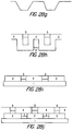
- the resin making up the layer will simultaneously shrink and adhere to layer 101, causing stress to be transmitted to this layer.
- layer 101 is somehow anchored to resist the transmittal of stress, both layers will curl upwards as illustrated in Figure 14b. If layer 100 were cured on multiple passes, on the other hand, it could be cured without transmitting a significant amount of stress to layer 101.
- layer 100 could be cured almost to the point of adhering to layer 101, but separated from it by distance 102, which could be on the order of a few mils. Then, in a subsequent pass, the layers would be adhered to one another, but since the amount of resin which is cured on the final pass is small, there will be less shrinkage on the final pass compared with a single pass, and therefore less stress transmitted to the lower layer.
- the second way multi-pass reduces curl is that when the adhesion pass is made, the resin being cured on the adhesion pass will be sandwiched in between a rigid already-cured layer below, and the rigid already-cured portion of the present layer above. With reference to FIG. 15b, the curing of this resin will simultaneously introduce stresses to both the upper and lower cured layers, which will tend to cancel each other out. For example, lower layer 101 will tend to bend upwards, while upper layer 100 will tend to bend downwards as indicated.
- a possible embodiment of multi-pass is to provide only two passes for a given layer, with adhesion (and possible over-curing to penetrate into the next layer for better adhesion) occurring on the second pass.
- a preferred embodiment of multi-pass is to provide more than two passes, i.e. four or five passes, for a given layer, such that after the first pass, an incremental amount of the uncured gap between the layers is incrementally cured on subsequent passes until a gap of only about two to three mils remains. Then, in a subsequent pass, the remaining two to three mil gap is cured, and adherence is achieved.
- the first pass it is not necessary for the first pass to bring the layers to within a few mils of each other. Instead, a wider gap can be left after the first pass, and it will be left up to subsequent passes to bring the layers to within a few mils of each other, and ultimately adhere. Therefore, if adherence takes place at all before the desired pass, it will surely not take place on the first pass, when a large amount of liquid resin will be cured, but will only take place on a later pass when only a relatively small volume of liquid resin will be cured. Also, according to Beer's law (discussed below), much less penetration of the cure depth will typically be achieved on a subsequent pass compared to a first pass, even if the exposure of the UV laser is kept the same on each pass.
- Imprecision in estimating cure depth is due to many sources.
- the cure depth depends logarithmically on the exposure from the UV laser, which means that doubling or tripling the exposure will not double or triple the cure depth, but will increase it much less than this.
- the lensing effect will occur because cured resin from previous pass will act as a lens, since the cured resin has a different index of refraction compared with the liquid resin.
- the laser beam will pass through the resin which has already been cured on previous passes, and the cured resin, as mentioned above, will act as a lens, and will focus the UV laser light, causing it to achieve a greater cure depth penetration than predicted using Beer's Law.
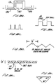
- FIG. 16a shows cured resin 103 produced by a single pass of the UV laser at a particular exposure.
- the cure depth achieved is identified as T 1 .
- FIG. 16b shows the cured resin produced by multiple passes of the UV laser beam, where the increase in the cure depth at each pass is identified with reference numerals 103a, 103b, 103c, and 103d, respectively. If it is assumed that the sum of the incremental exposures applied at each pass equals the exposure applied in the single pass of FIG. 16a, based on Beer's Law, it would be expected that T 2 would equal T 1 . However as illustrated, because of the lensing effect, T 2 will be greater than T 1 by an increment indicated as T 3 , which will be on the order of 50-76 ⁇ m (2-3 mils).
- a third reason for imprecision is variations in the intensity of the light produced by the laser, which, in turn, are caused by power fluctuations in the output of the laser.
- a laser presently used in the SLA-250 a commercial stereolithography apparatus manufactured by 3D Systems, Inc., has a continuous power output of approximately 20 mW. Because of power fluctuations, the laser output may be punctuated by 16-28 mW power bursts.
- the laser beam is directed to step across the surface of the liquid resin in incremental steps, and to then remain stationary for a given time period after each step.
- the exposure for the laser on an infinitesimal part of the liquid surface will be directly proportional to the laser output power multiplied by the step period divided by the step size. In other words, for a given laser output power, the exposure to the resin can be increased either by increasing the step period or decreasing the step size. Therefore, the fluctuations in laser output power will show up directly as fluctuations in exposure, with the result that the cure depth may vary by a few mils from what is expected because of these fluctuations.
- Another possible embodiment of multi-pass is to keep the laser exposure on each pass uniform. In many instances, however, uniform exposure on each pass will not be possible because of the impact of Beer's Law, according to which uniform increments of exposure at each pass will not lead to uniform increments in cure depth. Instead, much more will be cured on the first pass than on subsequent passes. For example, it is entirely possible for a first pass to cure 90% of the layer thickness, for a second pass to cure 90% of the uncured gap which remains left over after the first pass, and for a third pass to cure 90% of the remaining uncured gap left over after the second pass, etc. The result is that with uniform exposure, a layer may adhere only after two passes, with the additional passes resulting in even more adherence between the layers. As a result, in general, an embodiment where non-uniform exposures are possible on the various passes will be preferable.
- the first set of examples are for a two-pass embodiment of multi-pass.
- Example 2.) may be preferable since the top layer is cured closer to the bottom layer after the first pass, so that on the second pass, when adherence occurs, less resin will have to be cured.
- the optimum solution would require the exposure on the first pass to be in the range of 1/4-1/2, which would leave even less of a gap between the layers after the first pass.
- the exposure on the first pass it is preferable for the exposure on the first pass to be closer to 1/4 rather than 1/2. Therefore, Example 2.) is a preferred implementation compared with Example 3.).
- this example may not an acceptable implementation because adhesion occurs on the second pass, and in addition, due to the degree of imprecision involved, because some adhesion may, in all likelihood, occur on the first pass since the 0.50 mm (19.7 mil) cure depth is so close to the layer thickness of 0.51 mm (20 mils). Since there is a significant danger that adhesion may occur on the first pass, when the amount of liquid resin which is cured is great, this example is not a preferred embodiment of multi-pass.
- Example 7 is a preferable implementation, since much less resin will have to be cured on the third pass.
- a consideration in choosing exposure levels for the multiple passes is to avoid downward curl, a problem that can occur on a given pass if the cure depth achieved in previous passes is so small, that the curing of the liquid resin that takes place on later passes will cause the resin cured on the previous passes to bend downwards.
- adhesion to the lower layer can occur sooner than expected, which as described above, can introduce even more stress into the part by introducing upward curl of the bottom layer.
- This problem will be particularly acute if the incremental cure depth at each pass is uniform since, in this instance, the cured resin from the previous passes will (except for the first pass) be relatively thin, and therefore more easily bent by the curing during the later passes.
- the amount of downward bending will be dependent on the amount of resin which is cured during the later passes, since the more resin which is cured on the later passes, the more stress which is transmitted to the resin cured by the earlier passes.
- the amount of resin cured during the later passes may be relatively small, so that the downward bending problem may be alleviated by this type of implementation.
- FIG. 17a The problem of downward bending can be illustrated with reference to FIG. 17a, in which compared with the previous Figures, like references numerals are used to identity like components.
- bottom layer 101 is already cured, and layer 100 is being cured by multiple passes during which incremental amounts of liquid resin, identified by reference numerals 104a, 104b, and 104c, respectively, is cured.
- incremental amounts of liquid resin identified by reference numerals 104a, 104b, and 104c, respectively.
- resin 104c when resin 104c is cured, it shrinks and simultaneously adheres to cured resin 104b, transmitting stress and, causing downward bending.
- the downward bending at the ends of the already-cured portion of the layer, identified by reference numerals 105 and 106 respectively is great enough, the ends may touch the upper surface of layer 101, resulting in early adherence.
- One solution is to increase the thickness of the resin cured in the early passes, 104a and 104b, respectively, with respect to that cured during the later passes, 104c, or alternatively, to decrease the thickness of the resin cured during the later passes, 104c, compared with that cured during the early passes, 104a and 104b. This is illustrated in FIG. 17b, where, as before, compared with previous Figures, like components are identified with like reference numerals.
- birdnesting Another problem that can occur with multi-pass is birdnesting, which is a distortion that can occur if there are significant delays between the multiple passes.
- the problem occurs when resin cured on a particular pass is allowed to float for a long period of time on the surface of the liquid resin before additional passes adhere this cured resin to the layer below. If the delay is long enough, the cured resin floating on the surface of the resin can migrate about before it is adhered to the layer below.
- Birdnesting will be discussed in more detail below in the discussion of a commercial embodiment of multi-pass known as REDRAW, but it should be noted that a possible solution to the birdnesting problem is to reduce as much as possible the delays between successive passes.
- BUILD controls the laser movement through the use of two other programs, STEREO and LASER, and it obtains the parameters it needs to implement the numerous REDRAW functions based on information supplied in either 1.) a .PRM default parameter file in which a user can specify default REDRAW parameters; 2.) a .L layer control file in which a user can specify REDRAW parameters on a layer by layer, and vector type by vector type, basis; or 3.) a .R range control file in which a user can specify REDRAW parameters for a range of layers, and for vector types within a range. To implement the REDRAW functions, various command lines specifying REDRAW parameters are placed in either of these files similar to the way that other cure parameters are defined (as explained in the above co-pending applications).
- the first place BUILD looks for REDRAW control parameters is the .L or .R file, not both.
- the .L file enables a user to specify REDRAW parameters with a high degree of control.
- the .L file a user can specify REDRAW parameters for a particular vector type within a layer of an object. For example, for a .L file consisting of merged data for four objects, which data represents 11 different vector types, the .L file enables 44 different REDRAW parameters to be specified for each layer.
- the .L file provides layer by layer control of multi-pass.
- the .R file is designed for those applications whether the layer by layer control allowed by the .L file is not needed. Instead of providing layer by layer control, the .R file provides control on a range by range basis, where a range represents any number of adjacent layers.
- the REDRAW parameters can be placed into the .R file using a user interface program known as PREPARE.
- PREPARE a user interface program known as PREPARE.
- a standard word processor type line editor is used to place the REDRAW parameters into the .L file.
- BUILD requires any REDRAW parameters which it is unable to obtain from either the .L or .R files, then it will seek them from the .PRM default parameter file.
- REDRAW parameters can be placed in these files by use of the PREPARE program.
- the first REDRAW command is RC ##, where RC is a mnemonic for Redraw Count. This command specifies the number of passes that the laser beam will make over each vector of a cross-section, i.e., the number of passes for a particular layer. The number of passes specified can range from 1 to 10.
- the second REDRAW command is RD ####, where RD is a mnemonic for Redraw Delay.
- This command specifies the length of time the laser will wait at the beginning of each pass. As mentioned earlier, the laser beam moves across the surface of the resin in steps followed by delays at each step. The delay at each step is known as the Step Period, which is identified with the mnemonic SP, and the command for specifying a particular value of SP is the command SP ##, where the value chosen is in units of 10 microseconds.
- the value of RD can be specified as any number in the range of 0 to 65,535, which number represents the delay in units which are multiples of the SP value. Thus, an RD of 10 represents a delay of ten times the value specified for SP. In general, the RD command is not used much, and the standard value is 0.
- the RD command is similar to the JD command (which mnemonic stands for Jump Delay).
- the JD and RD commands are both necessitated by the inability of the software running on the PROCESS computer (which software controls the rotation of the dynamic mirrors, and hence the movement of the laser beam across the liquid resin) to take account of the time it takes for the laser beam to jump from a first vector to another vector, after it has drawn the first vector.
- the software will direct the beam to start drawing out another vector, perhaps beginning at a different location than the end of the previous vector, and will then simultaneously begin counting down the time for the laser to step through the vector as if the beam were instantaneously situated at the beginning of the next vector.
- the PROCESS computer will begin the counting while the laser beam is still jumping to the beginning of the vector.
- the PROCESS computer will immediately position it at the location it has counted down to, with the result that the first part of the vector maybe skipped over and left uncured.
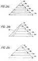
- FIG. 21b illustrates cross-section 105 of an object, and associated vectors 106a, 106b, 106c, 106d, and 106e spanning the surface of the cross-section, which vectors represent the movement of the laser beam as it cures the liquid plastic that forms the cross-section.
- the dotted lines between the head and tails of successive vectors is the movement of the laser as it jumps from one vector to another, and it is the jumping time for these jumps that causes the problem mentioned above.
- FIG. 21b The effect of the jumping time is illustrated in FIG. 21b, in which like elements are identified with like reference numerals compared with FIG. 21a.
- the jumping time results in an area, identified with reference numeral 107 in FIG. 21b, which is left uncured.
- JD and RD are designed to get around this problem.
- the delay specified by these commands is the time the PROCESS computer is directed to wait, after it has cured a particular vector, before it begins stepping through the next vector.
- RD is the time the PROCESS computer is directed to wait after it has completed a pass over a particular area, before it begins a next pass over that area.
- FIG. 21c illustrates a technique known as the "zig-zag" technique which is now implemented in the software to reduce the travel distance and hence jumping time between successive vectors.
- successive vectors 106a, 106b, 106c, 106d, and 106e instead of all pointing in the same direction as indicated in FIGS. 21a and 21b, are caused to alternate directions, as illustrated in FIG. 21c.
- the direction of these vectors indicates the movement of the laser beam on the surface of the resin as it traces out these vectors.
- This technique is also implemented in REDRAW, so that the laser beam will be caused to alternate directions every time it passes over a particular area in multi-pass. As a result, it is also frequently unnecessary to use the RD command.
- the third REDRAW command is RS ####, where RS is the mnemonic for Redraw Size. It was recognized early on that a problem with some forms of multi-pass was birdnesting, and to alleviate this problem, the RS command was added to enable long vectors in a given cross-section to be broken up into smaller mini-vectors so that multi-pass could be performed on each mini-vector before proceeding on to the next mini-vector. By choosing an appropriate size for the mini-vector, cured resin from the early passes could more rapidly be adhered to the layer below than if the entire vector were drawn on a given pass.
- the RS command specifies the length of the mini-vector into which the vectors of the cross-section are divided.
- the laser beam moves in steps, and the step size is identified by the mnemonic SS.
- the command for specifying the step size is SS ##, where the number specified can range from 0 to 65,538 bits, where a bit represents approximately 7.6 ⁇ m (.3 mil) (the actual tranlation is 140 bits/mm (3560 bits per inch).
- a particular pass can proceed over a distance which can range from a minimum of approximately 7.6 ⁇ m (.3 mils) to a maximum of approximately 508 mm (20 inches).
- the units of RS are multiples of SS. For example, an SS of 2, and an RS of 1000, indicates that each pass will draw 2000 bits of vector information before jumping back to make additional passes. Alternatively, with an SS of 8, and an RS of 1000, then 8000 bits of vector information will be drawn before beginning another pass.
- the last REDRAW command is a command for providing a different laser exposure value for each pass. This is accomplished by specifying a different SP value for each pass, since as indicated earlier, the exposure is directly proportional to SP.
- the format of the command is SP ####, ####, #### . . . . depending on the number of passes.
- the value of SP is in units of 10 ⁇ s, and in addition, each SP can range in value from approximately 5-15 to approximately 4000-6500.
- REDRAW parameters can be specified for each vector type in that layer using the .L file.
- all the REDRAW commands will be completed for a particular vector type, before REDRAW commands for the next vector type are expected.
- a typical command line in the .L file might appear as follows: 920, LB1, "RC 3; RD 0; RS 1000; SP 250, 150, 1000; SS 2.”
- This command indicates that at the layer of a first object located 920 vertical bits from the bottom, that for the layer boundary vectors for that object, identified by the mnemonic LB1, 3 passes will be performed for each boundary vector (indicated by the REDRAW command RC 3), each pass will draw 2000 bits of a boundary vector (indicated by the commands SS 2 and RS 1000) before proceeding on to the next pass, and the SP values for the first, second, and third passes, respectively, will be 250, 150, and 1000.
- a typical command in a .R file might appear as follows: LB1, "RC 3; RD 0; RS 1000; SP 250, 150, 1000; SS 2" which command is identical to that specified above for the .L file, except that no layer specification is provided, since this command will apply to all layers within a specified range.
- a command in the .PRM default parameter would look similar to this.
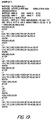
- FIG. 18 A sample report showing the format of the .L file is shown in FIG. 18. As illustrated, only vectors for a first object are represented, and REDRAW commands can be specified for each vector type within a layer of that object.
- the vector types and their associated mnemonics are as follows:
- boundary vectors are used to trace the perimeter of each layer
- cross hatch vectors are used to trace the internal portion of each layer surrounded by the layer boundary
- skill fill vectors are used to trace any outward surfaces of the object. They are traced in the following order: boundary, cross-hatch, and skin.
- FIG. 19 is a sample report showing the format of the .R file. As indicated, the format is similar to that for the .L file, except that the specifiction of REDRAW parameters is only possible for a particular vector type within a range of layers.
- the REDRAW commands for a particular range are framed by the mnemonics #TOP and #BTM, and in addition, the range of layers to which the REDRAW commands apply are provided in the line before the #TOP mnemonic.
- the range specified is 920, 920, which indicates that the range specified for the first block of REDRAW commands is the one layer located at 920 SLICE units from the bottom (assuming CAD/CAM units of inches, and a desired resolution of 1,000, the SLICE units will be mils.
- the difference between the CAD/CAM and SLICE reference scales is described in more detail in EP-A-0 354 637 This is because the beginning and ending points of the range are identical: 920 mils (23.4 mm). The ending point of the range could just as well have been specified as any other value in the CAD/CAM reference scale, in which case, the block of commands would apply to all layers in the specified range.
- FIG. 20 illustrates default parameters listed in a .PRM file, which parameters will be used if they are not specified in either the .L or .R files. As indicated, default parameters can be specified for each object (assuming more than one object is being built at the same time), and for each object, can be further specified for each vector type within any layer of that object.
- the default parameters specified for the layer boundary vectors of the first object are as follows: LB1, "RD 1; RS 300; RC 1; SP 20; JD 0; SS 8.”
- This command line is interpreted as follows: the default value for Redraw Delay is 1 (representing 200 ⁇ s given the default SP value of 20), for Redraw Size is 300 (representing 2400 bits or approximately 720 mils, given the default SS of 8), for Redraw Count is 1 (indicating single pass, i.e., layer boundary vectors are not to be multi-passed), for Step Period is 20 (representing 200 ⁇ s), for Jump Delay is 0 (indicating this command is not being used), and for Step Size is 8 (representing 8 bits or approximately 2.4 mils). Since the default value for RC is 1, this indicates that unless multi-pass is specified in either the .L or .R files for the layer boundary vectors, it will not be provided for these vectors.
- the commercial embodiment of REDRAW utilizes a technique known as the "short vector" technique, whereby any vector is divided up into a sequence of short mini-vectors, and the entire vector is multi-passed by successively multi-passing each of the mini-vectors.
- the objective of the short vector technique is to eliminate the problem of birdnesting, a problem which could occur if multi-passing were attempted on the full length of vectors as a whole, especially long vectors.
- the plastic cured during the early passes will be floating quite awhile on the surface of the liquid resin before they would be adhered to the lower layer through curing from subsequent, additional passes. As a result, this cured plastic can move before it is finally adhered to the layer below, a problem which can manifest itself as a distortion in the final part, which distortion resembles a birdnest, and hence is called birdnesting.
- boundary vectors are the only vectors where birdnesting may result from their being drawn through multiple passes since they are typically drawn in isolation from the other vectors, and do not therefore have anything to adhere to when they are drawn.
- Hatch vectors on the other hand, are usually drawn after the border vectors have been drawn, and they therefore adhere to the cured plastic from the border vectors when they are drawn, even if they are drawn in multiple passes.
- Skin and near-flat skin vectors also are typically drawn after the border and hatch vectors are drawn, and may adhere to the cured plastic from these vectors when they are drawn.
- the spacing between these vectors is typically very small (approximately 25-100 ⁇ m (1-4 mils), compared to a spacing of approximately 0.76-2.54 mm (30-100 mils) for hatch vectors), so that adherence will also take place with cured plastic from adjacent skin and near flat skin vectors.
- one solution to the birdnesting problem is to only multi-pass the hatch vectors, and not the border vectors. All the hatch vectors could be multi-passed, or alternatively, only a percentage of the hatch vectors could be multi-passed. Even if the hatch vectors did have a bowed down appearance from the multi-passing, this would not affect the outer appearance of the part.
- This solution is feasible in the commercial embodiment of REDRAW described above, since the use of the .L, .R, or .PRM files all allow multi-pass to be implemented only for selected vector types. Thus, REDRAW could only be provided for the hatch vectors.
- a third solution is to use a two pass implementation of multi-pass so that the cured plastic from the first pass will be adhered on the second pass, and will therefore only be floating for a short while.
- the disadvantage is that as mentioned earlier, more than two passes is beneficial for dealing with the imprecision in estimating cure depth. This disadvantage could be alleviated by only two pass multi-passing the border vectors (where birdnesting is a problem), but multi-passing with more than two passes for the remainder of the vectors.
- a fourth possible solution is to isolate the use of multi-pass to those areas of the part having critical volume features, that is areas that are most susceptible to distortion, such as cantilevered sections of a part. These areas can be isolated through the use of the .R file, which can be used to specify a range of cross sections to which multi-pass is to be applied.
- An important aspect of the commercial embodiment of REDRAW in version 2.62 of the software is the ability to specify different SP values (and hence different exposures) for different passes. As discussed earlier, it is frequently necessary to specify different exposure values for the different passes in order to prevent adhesion from occurring earlier than desired.
- the SP values should be chosen so that on the first pass, a large percentage of the gap between layers is cured, leaving an uncured area which is cured on successive passes, and which area has a thickness in the range of only 25-127 ⁇ m (1-5 mils) depending on the layer thickness and tolerances possible.
- the preferred size of the gap will depend on the layer thickness as follows: Layer thickness Uncured gap 0.51 mm (20 mils) 25-127 ⁇ m (1-5 mils) 0.25 mm (10 mils) 25-76 ⁇ m (1-3 mils) 0.13 mm (5 mils) 25-50 ⁇ m (1-2 mils)
- the size of the uncured gap remaining after the first pass can increase with the layer thickness. This is because the greater the layer thickness, the more plastic that will be cured on the first pass, which plastic will be less susceptible to downward bending from the shrinking of the plastic in the uncured gap as it is cured.
- the SP for the remaining passes should preferably be chosen to effectuate a 25-50 ⁇ m (1-2 mil) increase in cure depth per pass.
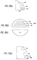
- FIGS. 22a-22f illustrate an example which combines the technique of using secondary structures and rivets to connect rails.
- FIGS. 22a-22f illustrate an example which combines the technique of using secondary structures and rivets to connect rails.
- FIGS. 22a-22f illustrate an example which combines the technique of using secondary structures and rivets to connect rails.
- FIGS. 22a-22f illustrate an example which combines the technique of using secondary structures and rivets to connect rails.
- FIGS. 22a-22f illustrate an example which combines the technique of using secondary structures and rivets to connect rails.
- FIGS. 22a-22f illustrate an example which combines the technique of using secondary structures and rivets to connect rails.
- like components are identified with like reference numerals.
- Figure 22a shows a side view of layers 107a, 107b, and 107c, which are shown stacked on top of each other.
- the layers have been cured in isolation from each other in order to reduce curl by eliminating the ability of the layers to transmit stress to one another while they
- FIG. 22a Each layer in FIG. 22a is actually comprised of two lines in parallel, and a top view of a layer is illustrated in FIG. 22b, which shows layer 107b as consisting of lines 107b(1) and 107b(2) in parallel. As shown, the lines for a given layer have also been cured in isolation from each other to reduce curl, and they must also be connected by some form of secondary structure in order to provide structure to the part.
- FIG. 22b is a top view of layer 107b, which illustrates secondary structure 108a, 108b, 108c, 108d, and 108e, for connecting the lines of a particular layer, in this case, lines 107b(1) and 107b(2) of layer 107b.
- the secondary structure also connects the lines of adjacent layers together, in this case, lines 107b(1) and 107b(2) are respectively connected to lines 107c(1) and 107c(2) by the secondary structure.
- FIG. 22c shows a side view of the lines of layer 107b stacked on top of the lines for layer 107c, and connected by secondary structure 108a, 108b, 108c, 108d, and 108e.
- the secondary structure has two aspects to it, and comprises supporting lines of lower exposure and an area of higher exposure known as rivets for connecting support lines from adjacent layers together. This is illustrated in FIGS. 22d and 22e.
- the secondary structure for layer 107b comprises, in part, connecting support lines 108a(1), 108b(1) 108c(1), 108d(1) and 108e(1) of lower exposure than lines 107b(1) and 107b(2) making up the layer (as a result of which the support lines have a lower cure depth than the lines making up the layer).
- the support lines are used to connect the lines making up a layer, in this case lines 107b(1) and 107b(2) of layer 107b.
- the secondary structure is comprised, in part, of areas of higher exposure known as rivets.
- these are identified as 108a(2), 108b(2), 108c(2), 108d(2), and 108e(2), respectively, which rivets are areas of heavier exposure than either the support lines or the lines making up a layer, the result of which is that the rivets have a cure depth which penetrates down to and adheres to the support lines of an adjacent layer.
- FIG. 22d which shows the rivets connecting the support lines for layers 107b and 107c.
- FIGS. 23a-23c An important aspect of rivets is illustrated in FIGS. 23a-23c, in which like components are indicated with like reference numerals. If lines on different layers are connected by rivets, then, in certain instances, it may be important to keep the diameter of the rivets smaller than the width of the lines. This, in turn, will be accomplished by keeping the exposure used to create the rivets low enough so that this condition does not occur.
- FIG. 23a illustrates a line with rivets 109a, 109b, and 109c, where the diameter of the rivets is much smaller than the width of the line.
- FIG. 23b illustrates a line where the diameter of the rivets is larger than those in FIG. 23a.
- FIG. 23c illustrates a line where the diameter of the rivets is even larger than the width of the line.
- the diameter of the rivets smaller than the width of the lines is only important when the lines form the outer surface of a layer of the part. In this instance, it is important to keep the rivet diameter smaller than the line width so that the outward surface of the part remains smooth. If the lines being riveted are support lines in the interior of the object, it may not be necessary to keep the diameter of the rivets smaller than the width of the lines. In fact, in this instance, as illustrated in FIGS. 22b and 22e, the diameter of the rivets can be greater than the width of the support lines.
- FIGS. 24a-24d This aspect of rivets is illustrated in more detail in FIGS. 24a-24d, in which like components are identified with like reference numerals.
- FIG. 24a illustrates a part comprising layers 107a, 107b, and 107c respectively, which layers are connected to adjacent layers by means of rivets 108a(2) and 108b(2) (for connecting layer 107a to 107b), and by means of rivets 109a(2) and 109b(2) (for connecting layer 107b to 107c).
- FIG. 24b A top view of rivets 108a(2) and 108b(2) is illustrated in FIG. 24b. If line 107b makes up the outer surface of the finished part, then if the diameter of the rivets is greater than the width of the line, a rough outer surface will be introduced.
- FIG. 24d shows lines 107b(1) and 107b(2) connected by lower exposure support lines, which support lines are connected to support lines of adjacent layers by rivets 108a(2) and 108b(2).
- line 107b(1) is connected to a line of an adjacent layer by means of rivets 111a(2) and 111b(2)
- line 107b(2) is connected to a line of an adjacent layer by means of rivets 110a(2) and 110b(2). If either of these lines forms the outer surface of the part, then as discussed above, the diameter of the rivets cannot be too large, or if it is, the rivets must be offset towards the interior of the part so they do not extend beyond the plane of the outer surface of the part.
- FIGS. 25a-25c illustrate another example of using a secondary structure to connect lines.
- like components are identified with like reference numerals.
- FIG. 25a successive structures 113a, 113b, 113c, and 113d are drawn, wherein each structure, as illustrated in FIG. 25c has a portion 113a(1) made with relatively low exposure, and another portion 113a(2) made with higher exposure.
- the exposure chosen to make the higher exposure portion should be such that successively stacked high exposure portions, 113a(2) and 113c(2) in the Figure, barely touch.
- successful parts have been made using this technique where successive high exposure portions are within 1.02-7.62 mm (40-300 mils) of each other, but this range is provided for illustrative purposes only, and is not intended to be limiting.
- FIG. 25b shows rivets 116a, 116b, and 116c holding together overlapping lower exposure portions from successive layers, 113a(1) and 113b(1) in the Figure.
- the outer surfaces 114 and 115 of the part are formed from the stacking of the higher exposed portions from successive layers, surface 114 being made up, in part, of stacked portions 113a and 113c, and surface 115 being made up, in part, of stacked portions 113b and 113d.
- curl reduction techniques described above reduce curl through one of three ways: 1.) reducing stress; 2.) resisting stress; and 3.) relieving stress.
- An example of 1.) is multi-pass where successive layers are cured through multiple passes so that when they do adhere, only a small amount of stress will be transmitted to adjacent layers.
- An example of 2.) is the multi-pass technique whereby as much of a layer as possible is cured on the first pass, so that this portion of the layer will be strong to both resist downward curling, and to resist the layer below from upward curling.
- An example of 3.) is dashed or bent lines, where stress is actually transmitted from one layer to another, but breaks or bends act to relieve the stress.
- FIGS. 26a-26c illustrate a part made with different curl reduction techniques.
- FIG. 26a shows the part made with dashed lines
- FIG. 26b shows bent lines
- FIG. 26c shows a part made using the secondary structure technique described above with respect to FIGSs. 25a-25c.
- FIG. 26a parts have been successfully built where the length of the solid portions of a line, identified with reference numeral 117a in the Figure, range from 1.02 to 7.62 mm (40 to 300 mils), and where the breaks between the successive solid portions, identified with reference numeral 117b in the Figure, were also in the range of 1.02 to 7.62 mm (40 to 300 mils).
- these ranges are illustrative only, and are not meant to be limiting.
- FIGS. 27a-27e Three variants of the techniques are available to alleviate these problems, which variants are illustrated in FIGS. 27a-27e, in which like components are identified with like reference numerals.
- the first variant is illustrated in FIG.27a.
- the solid portions of a dashed line are analogized to bricks, and the breaks between successive bricks are filled in with liquid resin analogized to mortar, which is then cured with less exposure than the bricks.
- a problem with this variant is that if the mortar is subsequently exposed at the same level as the bricks to improve strength, curl will be reintroduced.
- FIG. 27b shows the order in which the indicated portions are successively cured.
- the solid layer is drawn, and then on top of it are drawn spaced bricks, and then the interstices between the bricks are filled with mortar, which interstices are then cured, preferably at a lower exposure than the bricks.
- An advantage of curing the bricks on top of the solid layer is so that the solid layer will be strong to resist upward curl.
- FIG. 27c shows the order in which the indicated portions are cured. As indicated, bricks are drawn on one layer, and then on the next layer, bricks are also drawn, but offset from those on the first layer, so that the bricks on the second layer span the interstices between the bricks on the first layer. A problem with this technique is that it results in almost as much curl as if standard solid lines were drawn.
- FIGS. 27d and 27e show other variations of the dashed line technique, where the numerals indicate the order of drawing the indicated solid portions.
- FIG. 27d shows placing a first dashed line on a solid line, and a second offset dashed line placed on the first dashed line.
- FIG. 27e shows placing several dashed lines on a solid line which are lined up, and then offsetting successive dashed lines.
- FIGS. 28a-28i The bent line technique illustrated in general in FIG. 26b, and variants on this technique are illustrated in FIGS. 28a-28i.
- the basic idea of the bent line technique is to relieve the stress transmitted to a given layer from adjacent layers.
- stress introduced to portions 118a and 118b of line 118 are taken up by lateral movement of these portions into gap 118c. This is because something must give to relieve the stress, and in the example of FIG. 28a, what gives is the portions 118a and 118b, which are allowed to move laterally into gap 118c.
- Parts have been successfully built with the dimensions indicated in FIG. 28b, that is with the solid portions of a line in the range of 1.02-7.62 mm (40 - 300 mils), and the gaps between the solid portions also in this range.
- Other examples are possible, and the indicated ranges are intended to be illustrative only, and not limiting.
- the size of the gaps should preferably be as small as possible, but as a practical matter, the size of the gaps depends on the tolerances possible, because it is crucial that successive solid portions do not touch. In the example of FIG. 28a, it is crucial that gap 118c is not so small that solid portions 118a and 118b touch. If they touch, then curl will result.
- FIG. 28c shows an example of a bent line where the gaps are much smaller than the length of the solid portions.
- bent lines can be much stronger than dashed lines, and in addition, their stress resistance can be much greater after a part is built using bent lines.
- FIG. 28d shows a variant of a bent line where the bends in the line have a triangular shape. Parts have been successfully built with each triangular bend on the order of 6.35 mm (250 mils (1/4 inch)) in length.
- the angle of the vertex of each triangular bend although indicated at 90° in FIG. 28d, can vary from this. In fact, if made smaller than this, the resulting line will resemble that in FIG. 28c, and even more curl can be eliminated. If the angle is made greater than this, the bent line will resemble a straight line, and the curl effect will be more pronounced.
- FIGS. 28e and 28f Another variant of a bent line is illustrated in FIGS. 28e and 28f.
- FIG. 28e parts have been successfully built using bent lines where the bends in the line have an inverted triangular shape as illustrated, and where each bend has in FIG. 28f the dimensions indicated, that is, a width of 3.18 mm (125 mils (1/8 inch)), with the gaps between successive solid portions 40 mils or smaller, and with the angles of each triangular bend at 45°, 45°, and 90°, respectively.
- FIG. 28g shows another variant of a bent line technique where the bends have a trapezoidal shape.
- Other examples are possible, and the examples above are intended to be illustrative only, and are not intended to be limiting.
- FIG. 28h illustrates the technique of filling in the gaps in the line with liquid resin and then partially exposing the resin in the gaps.
- the numbers indicate the order in which the portions shown are cured.
- FIG. 28i Another variant is to place a bent line on a solid line as indicated in FIG. 28i, which has the advantage that the solid line drawn first resists upward curl.
- FIG. 28h the gaps in the bent line are filled in with resin and partially exposed. The order in which the curing takes place is indicated by the numerals in the Figure.
- FIG. 28j illustrates another variant where a first bent line is placed on a solid line, and a second bent line is placed on the first bent line but offset from the first bent line so that the solid portions of the second bent line span the gaps in the first bent line.
- the numerals indicate the order in which the portions indicated in the Figure are cured.
- FIG. 29a illustrates an undistorted cantilevered section 120, made up of individual layers 120a, 120b, 120c, 120d, and 120e, which adhere to adjacent layers as shown to make up the overall section.
- the cantilevered section is what is commonly referred to as a rail. As shown, the section is supported by supports 120 which in turn make direct contact with platform 122.
- the axis of the section is also indicated in the Figure.
- FIG. 29b illustrates the same cantilevered section reflecting the distortion caused by curl.
- like components are identified with like reference numerals.
- the direction of the curl is upwards, in the same direction as the axis of the cantilevered section.
- FIG. 29c is a top view of layer 102d of the sections showing the direction of the vectors that contribute to adhesion between layer 102d and layer 102e. As shown, the direction of these vectors is all perpendicular to the direction of distortion, and therefore to the axis of the cantilevered section.
- boundary vectors are used to trace the parimeter of a layer
- cross hatch vectors and used to trace the internal portions of a layer
- skin fill vectors are used to trace any outward surfaces of a part. They are traced in the following order: boundary, cross hatch, and skin fill. The following list shows the correspondence between these mnemonics:
- the first aspect of the vector-based implementation of rivets is specifying a critical area of a particular layer or layers in which rivets will be placed. These critical areas are specified by creating what is known as a critical box file. This file contains one or more box specifications enclosing volumes that will either have their crosshatch vectors riveted or not scanned at all. An XV placed at the beginning of a box specification indicates that crosshatch vectors inside the box will be riveted while an XI placed at the beginning of a box specification indicates that crosshatch vectors inside the box will not be scanned.
- the critical box file is an ASCII file generated by any convenient text editor and is given the same name as that of the output files (the .L and .V files) that will be created by the MERGE program, which merges .SLI files for different objects before beginning the process of tracing out vectors (described in more detail in EP-A-354 637, except it will have the extension .BOX instead of .L or .V.
- the CAD file for an object is referred to as the .STL file for that object.
- MERGE then merges the .SLI file for different objects to form a .V file containing the merged vector data, and also a .L file for control purposes.
- the BUILD program then takes the .V and .L files, and begins tracing out the vectors.
- the MERGE program begins to merge its input .SLI files for different objects, it looks for a corresponding .BOX file. If this file is found, MERGE then appends critical area designations onto all layers that are indicated as requiring them.
- a single box consists of a rectangular volume for a particular vector type followed by its position in space.
- a typical specification might look like, "XV,.94,.04,.250,8.750,.250,.250,4.375,.250,4.375,8 .750"
- the XV indicates that this box surrounds a volume to be riveted.
- the 0.94 indicates the location of the bottom of the box in the same units and reference scale as that used in the CAD design of the part. If the CAD units are inches, the 0.94 indicates that the bottom of the box is .94 inches from the bottom of the CAD space.
- the 0.04 represents the height of the box in CAD units (inches in the above example) above the bottom.
- the next eight numbers are read as XY pairs that indicate the corners of the box in CAD units and are based on the location of the part in space as designated by the CAD system.
- FIG. 30 shows the format of a typical .BOX file (entitled for illustrative purposes only as RIVET.BOX), which file describes two boxes specifying volumes that will be riveted.
- the example shows the file as consisting of a single text line which is wrapped around for printing purposes only.
- a benefit of the MERGE program is that different riveting parameters can be specified for different subvolumes of an object by placing the different subvolumes into separate .STL files, slicing them separately into different .SLI files for each subvolume, and then merging them. This is because different riveting parameters can be specified for each .SLI file. More details on the .SLI and .STL file formats are provided in EP-A-0 354 637.
- the .L file is created by a standard text editor, and is used by BUILD (or SUPER, depending on the software version) program for layer to layer control of the curing process.
- the R. file which provides control for a range of layers, is not available to control riviting for the particular implementation of rivets described here.
- the .PRM file is used by BUILD to obtain default riveting parameters when a particular parameter is not specified in the .L file.
- the .L file is used to control riveting on a layer by layer basis, and within a layer, on a vector type by type basis.
- the .PRM file is used only in those instances where a critical riveting parameter is not specified in the .L. file.
- FIG. 31 The format of a .L file for use in controlling riveting is provided in FIG. 31.
- the file is named RIVIT.L for illustrative purposes only, and shows layer 920 with no rivet parameters specified.
- Layer 940 has a number of riveting commands which apply to it, which commands are framed by the #TOP and #BTM mnemonics.
- RIVET.BOX where parameters are specified in CAD units
- parameters in the .L and .PRM files are specified in SLICE units.
- CAD units are the units in which an object is designed on a CAD system, and are the units associated with the .STL file for an object.
- SLICE units are the units into which the object is sliced into layers by the SLICE program, and is associated with the .SLI file for that object.
- CAD units in inches, for example, and a desired SLICE resolution of 1,000, the SLICE units will be in mils.
- CAD units, SLICE units and resolution are described in more detail in EP-A-0 354 637.
- the first riveting command line specified for layer 940 is "#CA XV, 250, 250, 3750, 250, 3750, 8750, 250, 8750" where the mnemonic #CA stands for Critical Area.
- This command is similar to the .BOX file discussed earlier, and specifies a critical box, within which the cross hatch vectors are either riveted or not scanned at all.
- the XV mnemonic indicates that the cross hatch vectors will be riveted.
- the next eight numbers are four XY pairs (in SLICE units) that describe the corners of box which makes up the critical area.
- the next command line for layer 940 is a command which applies only to "Z" vectors (which are layer boundary vectors, and as per the table provided earlier, are referred to in later implementations with the mnemonic "LB"). As indicated, the command line is "SS 8; SP 100; JD 0: RC 1", which since a VC command is not specified, indicates that the layer boundary vectors are not being rivetted.
- the next command line for layer 940 applies only to the "X" vectors (as per the above table, X cross hatch is now combined with Y and 60/120 cross hatch into the single mnemonic "LH”) and is as follows: "SS 8; SP 100; JD 0; RC 1; VC 2; VR 500; VP 20, 100".
- the "VC 2" command specifies a Rivet Count of two passes, where an exposure of 20 is specified for the first pass, and an exposure of 100 is specified for the second pass. Given exposure units of 10 ⁇ s, this translates into an exposure of 400 ⁇ s, and 1,000 ⁇ s, respectively.
- the command "VR 500" indicates that for the second pass, the X cross hatch vectors will only be riveted to within 500 SS multiples from where the cross hatch vectors join the layer boundary vectors. Given an SS of 8 bits (approximately 2.4 mils), this translates into an offset of approximately 1,200 mils (1.2 inches) from the ends.
- FIG. 32 shows an example of a .PRM file, entitled SUPER.RPM for illustrative purposes only.
- the .PRM file is described in greater detail in EP-A-0 354 637, and only the aspects of the example pertaining to default riveting parameters will be described here.
- the only default riveting parameters indicated are for the layer cross hatch vectors for the first object (described in the Figure by the mnemonic "LH1", which as per the table above, in earlier implementations, would have been described with the mnemonics "X”, “Y” or “I”, for X, Y, or 60/120 cross hatch, respectively) and for the near flat down facing skin vectors for the first object (described in the Figure with the mnemonic, "NFDH1," which, as per the table, would have been described in earlier implementations with the mnemonics "F”, “G”, and “K”, for X, Y, or 60/120 cross hatch, respectively).
- the relevant portion of the file is reproduced below:
- the portion of each line following the "! is a comment for readability purposes only.
- the default Rivet Count is 5 passes, with an exposure of 11, 12, 13, 14 and 15 specified for each respective pass (which given exposure units of 10 ⁇ s, translates into exposures of 110, 120, 130, 140, and 150 ⁇ S, respectively).
- the default Rivet Reduction amount is 99 SS multiples, which given the default SS of 8, translates into a value of 792 bits or approximately 6.035 mm (237.6 mils).
- the default riveting parameters are identical to those specified for the layer cross hatch vectors.
- the .V file produced by MERGE is illustrated in FIG. 33.
- the file consists of the vectors to be traced for each layer divided into the various vector types.
- the XY pairs for the layer boundary vectors are listed followed by the XY pairs for the cross hatch vectors (indicated by the mnemonic "X1").
- the layer boundary and cross hatch vectors are listed for layer 940.
- the quarter-cylinder is actually a cantilevered beam made up of a number of layers which adhere to adjacent layers to form the overall beam.
- An aspect of the quarter-cylinder is the measurement of upward (or vertical) curl, which results from the adhesion of layers to adjacent layers.
- FIGS. 34(a) and 34(b) provide a side view of a quarter cylinder which shows the effects of upward curl.
- the quarter cylinder comprises cantilevered beam 120 made up of layers 120a, 120b, and 120c, which are supported by platform 121.
- FIG. 34a shows the quarter-cylinder before the effects of upward curl have been introduced
- FIG. 34b shows the same quarter-cylinder after the effects of upward curl have been introduced.
- 34b illustrates another aspect of upward curl, which is that as the number of cured layers increases, they become more effective in resisting the torque produced by the successively cured layers. As a result, in the example of FIG. 34b, by the time layer 120c is cured, the effects of upward curl have just about disappeared.
- FIGS. 34c and 34d illustrate a top view of layer 120a comprising lines 123a, 123b, and 123c, respectively, while FIG. 34d shows the effects of horizontal curl on the same layer. As indicated, as more lines are built, the effects of horizontal curl become less pronounced since the already cured lines become better able to resist the torque exerted by successive lines.
- FIG. 35a A specific example of a quarter cylinder is illustrated in FIG. 35a.
- the part comprises upper layers 124, support layer 125, post-layers 126, and base layer 127.
- upper layers 124 comprise 25 layers
- post-layers 126 comprise 8 layers
- base layer 127 comprises 1 layer
- support layer 125 comprises 1 layer.
- Other examples are possible, however, and this example is provided for illustrative purposes only, and is not intended to be limiting.
- each layer advantageously comprises inner and outer concentric circularly curved rails, 128 and 129 respectively, where the inner rail has a radius of 27 mm and the outer rail has a radius of 30 mm.
- the curved rails subtend an angle of 5 ⁇ /12 radians, slightly less than 90°.
- post layers 126 comprise post-pairs 126a, 126b, 126c, and 126d, and as illustrated in FIG. 35c, each post-pair advantageously comprises two posts.
- Post-pair 126a for example, comprises posts 126a(1) and 126a(2), respectively.
- ⁇ /4 radians a little over half, of the concentric arc is supported by posts, with each post pair advantageously uniformally spaced by ⁇ /12 radians along the supported portion of the arc.
- the inner and outer rails of a layer are advantageously connected by 21 uniformally spaced support lines of lower exposure (which are analogous to cross hatch vectors described in EP-A-0 354 637, and which therefore will be known here simply as cross hatch), where each line is advantageously uniformly spaced by ⁇ /48 radians.
- the cross hatch is exposed at a lower exposure so that the cross hatch for a given layer does not initially adhere to cross hatch for an adjacent layer.
- the center of every other cross hatch on a given layer is given extra exposure, i.e. riveted, so that it adheres to the cross hatch below at this location.
- successive rivets for a particular layer are identified with reference numerals 130a, 130b, and 130c, respectively.
- the use of rivets is a technique for reducing upward curl.
- the part is advantageously built with 0.25 mm (10 mil) layers, but the exposure is varied amongst layers to provide different cure depths. This allows the measurement of curl at different cure depths.
- the base layer is advantageously given enough exposure to ensure good adhesion to the elevator platform (not shown), which corresponds to a 30 mil cure.
- the posts are advantageously given enough exposure to ensure good adhesion to the previous layer, which also corresponds to a 0.76 mm (30 mil) cure.
- the support rail is advantageously given a 0.76 mm (30 mil)cure to assure sufficient strength to resist resin currents during dipping.
- the rivets are advantageously exposed at a cure depth of 0.76 mm (30 mils), to ensure layer to layer adhesion of the lines of the upper layers.
- the upper lines, both inner and outer, and the supporting cross hatch lines are advantageously exposed at a varying cure depth, which parameter is varied to developed a curve of cure depth versus curl for the particular curl reduction technique used to make a quarter cylinder.
- An overall perspective of a quarter cylinder is provided in FIG. 35f.
- the cure depth of the lines of the upper layers can be varied between 25 or 51 ⁇ m (one or two mils) up to 1.02 mm (40 mils).
- the thickness of the quarter cylinder is measured at two locations: 1.) at the first rivet from the unsupported end of the upper layers, which location is identified with reference numeral 131 in FIG. 35g, and the thickness at this location is identified as "s" in the Figure: and 2.) at the first rivet from the supported end of the upper layer, which location is identified with reference numeral 132 in the Figure, and the thickness at this location is identified as "f” in the Figure.
- the curl factor for a given cure depth is defined as the ratio f/s.
- the curl factor for a range of cure depths are computed, and then plotted against cure depth. After a particular curve is plotted, the above would be repeated for different curl reduction techniques, to find the best curl reduction technique for a particular application.
- the above describes the use of a secondary structure combined with rivets to reduce curl, but other techniques described earlier, such as dashed or bent lines, multi-pass, etc., are possible to evaluate with this technique.
- FIG. 35h illustrates several such plots for different curl reduction techniques.
- inner and outer lines 129 and 128, respectively, when inner and outer lines 129 and 128, respectively, are cured, they will shrink by the same approximate percentage. Since the percentage of shrink is about the same, the extent to which the radius of the outer line shrinks will be greater then the extent to which the inner line shrinks, since for the larger radius, a greater incremental change is required to achieve to same percentage change. The result is that the outer line will transmit more stress to the surrounding structure. The presence of the cross hatch will prevent the relieving of the stress by movement of the outer line inwards towards the inner line. Therefore, to relieve the stress, the outer line typically moves upwards to produce the effect known as sneer. Note that the effect of sneer will be more pronounced the larger the radius of the cross section of the part under examination.
- FIGS. 36a-36c illustrates a side, front, and top view of a particular part having slotted sections 131a, 131b, and 131c.
- FIG. 36d shows that the areas of the part at the outer radius distort more, and in some instances, shown at slot 131c in the Figure, the distortion is so great as to cause the solid portion of the part to split. This is indicated with reference numeral 131d in the Figure.
- the quarter-cylinder can also be used to evaluate the impart on sneer of the various techniques described above.
Landscapes
- Engineering & Computer Science (AREA)
- Materials Engineering (AREA)
- Chemical & Material Sciences (AREA)
- Manufacturing & Machinery (AREA)
- Physics & Mathematics (AREA)
- Optics & Photonics (AREA)
- Mechanical Engineering (AREA)
- General Physics & Mathematics (AREA)
- General Engineering & Computer Science (AREA)
- Health & Medical Sciences (AREA)
- Thermal Sciences (AREA)
- Oral & Maxillofacial Surgery (AREA)
- Toxicology (AREA)
- Crystals, And After-Treatments Of Crystals (AREA)
- Heating, Cooling, Or Curing Plastics Or The Like In General (AREA)
- Stringed Musical Instruments (AREA)
Claims (45)
- Un processus pour former un objet tridimensionnel (30) dans lequel l'objet (30) est construit à partir de strates superposées (30a, 30b, 30c) formées chacune par solidification sélective d'une couche d'un milieu fluide transformable (22) par exposition à une stimulation prescrite (27) où la formation d'au moins une strate (30a, 30b, 30c) à partir d'une couche du milieu fluide est caractérisée par :au moins une exposition initiale de la couche à la stimulation prescrite (27) selon un motif prédéterminé pour former une section initiale de strate (30a, 30b, 30c) qui n'adhère pas directement à la strate précédente (30a, 30b, 30c) etau moins une autre exposition à la stimulation prescrite (27) selon un motif prédéterminé pour former une autre section de la strate (30a, 30b, 30c) reliant, au moins en partie, la section initiale directement à la strate précédente (30a, 30b, 30c).
- Un processus tel que revendiqué dans la revendication 1, où ladite exposition initiale au moins comprend l'exposition d'au moins une ligne et où ladite autre exposition au moins réexpose ladite ligne au moins.
- Le processus de la revendication 1, dans lequel ladite exposition initiale au moins comprend l'exposition d'au moins une ligne et où ladite autre exposition au moins ne réexpose qu'une partie de ladite ligne au moins.
- Un processus tel que revendiqué dans la revendication 3, où ladite autre exposition au moins donne des parties de la strate en des endroits choisis par lesquels la strate est reliée à la précédente strate (fig. 24).
- Un processus tel que revendiqué dans les revendications 1 à 4, où ladite exposition initiale au moins est une exposition unique.
- Le processus de l'une des revendications 1 à 4, où ladite exposition initiale au moins comprend au moins deux expositions.
- Un processus tel que revendiqué dans l'une des revendications 1 à 6, où ladite autre exposition au moins est une exposition unique.
- Un processus tel que revendiqué dans l'une des revendications 1 à 6, où ladite autre exposition au moins comprend au moins deux expositions.
- Un processus tel que revendiqué dans la revendication 1, où chaque exposition de la couche est du même motif prédéterminé, une succession d'expositions est utilisée pour approfondir progressivement la solidification de la couche vers la strate précédente et ensuite pour adhérer à la strate précédente (fig. 16B).
- Un processus tel que revendiqué dans l'une des revendications 2 à 8, où ladite exposition initiale au moins et ladite autre exposition initiale au moins sont opérées par le tracé d'un faisceau de stimulation prescrite sur une surface du milieu fluide.
- Un processus tel que revendiqué dans la revendication 10, où aussi bien ladite exposition initiale au moins que ladite autre exposition initiale comprennent l'exposition d'au moins une ligne et sont réalisées de manière à intervenir sur une partie de ladite ligne au moins avant l'exécution de toute exposition sur une partie résiduelle de ladite ligne au moins.
- Un processus tel que revendiqué dans la revendication 9, 10 ou 11, où différentes quantités d'exposition sont appliquées à chacune des dites expositions au moins.
- Un processus tel que revendiqué dans l'une des revendications 1 à 12, où l'on fait adhérer une partie de frontière de la strate à la strate précédemment formée en deux expositions et où l'on utilise un plus grand nombre d'expositions pour faire adhérer au moins une partie de la fraction intérieure de la strate à la strate précédemment formée.
- Un processus tel que revendiqué dans l'une des revendications 1 à 12, où l'on fait adhérer une partie de frontière de la strate à la strate précédemment formée en une seule exposition.
- Un processus tel que revendiqué dans l'une des revendications 1 à 14, où l'on applique ladite exposition initiale au moins et ladite autre exposition au moins dans une région critique de la couche susceptible de distorsion due au cintrage.
- Un processus tel que revendiqué dans l'une des revendications précédentes, appliqué à la formation de chaque strate d'une séquence de strates consécutives.
- Un processus tel que revendiqué dans la revendication 16, où la mise en place et l'exposition de couches successives du milieu fluide transformable (22) pour former la séquence consécutive de strates (30a, 30b, 30c) est opérée automatiquement sous le contrôle d'un programme prescrit.
- Un processus tel que revendiqué dans l'une des revendications 1 à 17, où la stimulation prescrite est un rayonnement, une lumière ultraviolette, une lumière visible, une lumière invisible, un bombardement de particules, des faisceaux d'électrons ou des réactifs chimiques.
- Un processus tel que revendiqué dans la revendication 18, où la stimulation prescrite est un faisceau de rayonnement ultraviolet.
- Un processus tel que revendiqué dans l'une des revendications 1 à 19, où le milieu fluide transformable est un polymère liquide.
- Un processus tel que revendiqué dans l'une des revendications 1 à 18, où le milieu fluide transformable comprend un métal ou une poudre de plastique.
- Un dispositif pour former un objet tridimensionnel (30) à partir de strates superposées (30a, 30b, 30c) formées chacune par la solidification sélective d'une couche d'un milieu fluide transformable par exposition à une stimulation prescrite (27), comprenant une source de stimulation prescrite (26), des moyens pour produire des couches successives de milieu fluide transformable (22) en préparation pour former des strates successives (30a, 30b, 30c) de l'objet et des moyens pour exposer sélectivement chacune de ces couches à une stimulation prescrite (27) pour former des strates successives (30a, 30b, 30c), où les moyens pour exposer sélectivement chacune des couches sont contrôlés par un dispositif de contrôle (25) pouvant fonctionner selon un programme prescrit, caractérisé en ce que :le dispositif de contrôle contrôle les moyens pour exposer sélectivement chacune des couchespour appliquer au moins une exposition initiale de stimulation prescrite (27) à la couche selon un motif prédéterminé pour former une section initiale de la strate (30a, 30b, 30c) qui n'adhère pas directement à la strate précédente (30a, 30b, 30c), etpour appliquer au moins une autre exposition de stimulation prescrite (27) à la couche selon un motif prédéterminé pour former une autre section de la couche (30a, 30b, 30c) reliant, au moins en partie, la section initiale directement à la strate précédente.
- Dispositif selon la revendication 22, où l'application de ladite exposition initiale au moins comprend l'exposition d'au moins une ligne et où l'application de ladite autre exposition au moins comprend la réexposition de ladite ligne au moins.
- Dispositif tel que revendiqué dans la revendication 22, où l'application de ladite exposition initiale au moins comprend l'exposition d'au moins une ligne et où l'application de ladite autre exposition au moins comprend la réexposition d'au moins une partie de ladite ligne au moins.
- Dispositif tel que revendiqué dans la revendication 24, où l'application de ladite autre exposition au moins comprend la liaison de la section initiale à la strate précédente en des emplacements choisis (fig. 24).
- Dispositif tel que revendiqué dans l'une des revendications 22 à 25, où l'application de ladite exposition initiale au moins est l'application d'une exposition unique.
- Dispositif tel que revendiqué dans l'une des revendications 22 à 25, où l'application de ladite exposition initiale au moins est l'application d'au moins deux expositions.
- Dispositif selon l'une des revendications 22 à 27, où l'application de ladite autre exposition au moins est l'application d'une exposition unique.
- Dispositif tel que revendiqué dans l'une des revendications 22 à 27, où l'application de ladite autre exposition au moins est l'application d'au moins deux expositions.
- Dispositif tel que revendiqué dans l'une des revendications 22 à 29, où la source est configurée de manière à produire la stimulation prescrite sous forme d'un faisceau et les moyens pour exposer sélectivement la couche sont configurés pour contrôler le traçage sélectif de ce faisceau de stimulation prescrite sur une surface du milieu fluide.
- Dispositif tel que revendiqué dans la revendication 30, où aussi bien l'application de ladite exposition initiale au moins que l'application de ladite autre exposition au moins comprennent l'exposition d'au moins une ligne et sont contrôlées pour exposer une partie de ladite ligne au moins avant d'opérer toute exposition sur une quelconque partie restante de ladite ligne au moins.
- Dispositif tel que revendiqué dans la revendication 30 ou 31, où l'on applique des quantités différentes d'expositions sur au moins deux des expositions.
- Dispositif tel que revendiqué dans l'une quelconque des revendications 22 à 32, où le programme prescrit possède des données, qui lui sont associées, pour exposer une partie de frontière d'une strate à former à partir d'une couche du milieu fluide de telle sorte que la partie de frontière adhère à la strate précédemment formée en deux expositions, et l'on utilise un plus grand nombre d'expositions pour faire adhérer au moins une partie de la fraction intérieure de la même strate à la strate précédemment formée.
- Dispositif tel que revendiqué dans l'une des revendications 22 à 32, où l'on fait adhérer une partie de frontière de la strate à la strate précédemment formée en une seule exposition.
- Dispositif tel que revendiqué dans l'une des revendications 22 à 34, où l'application de ladite exposition initiale au moins et l'application de ladite autre exposition au moins sont configurées de manière à exposer la couche de milieu fluide en une région critique susceptible de distorsion par cintrage.
- Dispositif tel que revendiqué dans l'une des revendications 22 à 35, dans lequel le programme fait en sorte que l'application de ladite exposition initiale au moins et l'application de ladite autre exposition au moins sont effectuées dans l'exposition d'une pluralité de couches consécutives.
- Dispositif tel que revendiqué dans l'une des revendications 22 à 36, où :
les moyens pour produire des couches successives de milieu fluide transformable et les moyens pour exposer sélectivement chacune de ces couches sont actionnables par le programme prescrit de manière à contrôler automatiquement la production des couches successives du milieu fluide et la formation des strates à partir de ces dernières. - Dispositif tel que revendiqué dans l'une des revendications 22 à 37, où la source de stimulation prescrite est une source de rayonnement, de lumière ultraviolette, de lumière visible, de lumière invisible, de particules, d'électrons ou de réactifs chimiques.
- Dispositif tel que revendiqué dans la revendication 38, où la source de stimulation prescrite est une source d'un faisceau de rayonnement ultraviolet.
- Dispositif tel que revendiqué dans l'une des revendications 27 à 39, où le milieu fluide transformable est un polymère liquide.
- Dispositif tel que revendiqué dans l'une des revendications 27 à 39 où le milieu fluide transformable comprend un métal ou une poudre plastique.
- Un processus pour former un objet tridimensionnel (30) dans lequel l'objet (30) est construit à partir de strates superposées (30a, 30b, 30c) formées chacune par solidification sélective d'une couche d'un milieu fluide transformable (22) par exposition à une stimulation prescrite (27) où la formation d'au moins une strate (30a, 30b, 30c) à partir d'une couche du milieu fluide est caractérisée par :au moins une exposition initiale de la couche à la stimulation prescrite (27) selon un motif prédéterminé pour former deux sections latéralement distinctes (107b(1), 107b(2)) de la couche qui n'adhèrent pas directement ensemble (fig. 22E, fig. 24D), etau moins une autre exposition à la stimulation prescrite (27) selon un motif prédéterminé pour former une structure (108) reliant les sections distinctes et laissant des parties non solidifiées de la couche entre ces sections.
- Le processus tel que revendiqué dans la revendication 42, où les sections distinctes ont des côtés qui se font face sur une longueur donnée et la structure (108) relie les côtés sur moins de cette longueur donnée.
- Un dispositif pour former un objet tridimensionnel (30) à partir de strates superposées (30a, 30b, 30c) formées chacune par la solidification sélective d'une couche d'un milieu fluide transformable par exposition à une stimulation prescrite (27), comprenant une source de stimulation prescrite (26), des moyens pour produire des couches successives de milieu fluide transformable (22) en préparation pour former des strates successives (30a, 30b, 30c) de l'objet et des moyens pour exposer sélectivement chacune de ces couches à une stimulation prescrite (27) pour former des strates successives (30a, 30b, 30c), où les moyens pour exposer sélectivement chacune des couches sont contrôlés par un dispositif de contrôle (25) pouvant fonctionner selon un programme prescrit, caractérisé en ce que :le dispositif de contrôle contrôle les moyens pour exposer sélectivement chacune des couchespour appliquer au moins une exposition initiale de stimulation prescrite (27) à la couche selon un motif prédéterminé pour former deux sections latéralement distinctes (107b(1), 107b(2)) de la couche qui n'adhèrent pas directement ensemble (fig. 22E, fig. 24D), etpour appliquer au moins une autre exposition de stimulation prescrite (27) à la couche selon un motif prédéterminé pour former une structure (108) reliant les sections distinctes et laissant des parties non solidifiées de la couche entre ces sections.
- Dispositif tel que revendiqué dans la revendication 44, où :
la formation des sections latéralement distinctes est contrôlée de manière que ces sections distinctes présentent des côtés en vis-à-vis sur une longueur donnée, et la formation de la structure est contrôlée de manière que cette structure (108) relie ces côtés sur moins de ladite longueur donnée.
Priority Applications (1)
| Application Number | Priority Date | Filing Date | Title |
|---|---|---|---|
| EP96114443A EP0747203B1 (fr) | 1988-04-18 | 1989-04-17 | Réduction du gauchissement stéréolithographique |
Applications Claiming Priority (4)
| Application Number | Priority Date | Filing Date | Title |
|---|---|---|---|
| US18282388A | 1988-04-18 | 1988-04-18 | |
| US182823 | 1988-04-18 | ||
| US339246 | 1989-04-17 | ||
| US07/339,246 US5104592A (en) | 1988-04-18 | 1989-04-17 | Method of and apparatus for production of three-dimensional objects by stereolithography with reduced curl |
Related Child Applications (2)
| Application Number | Title | Priority Date | Filing Date |
|---|---|---|---|
| EP96114443A Division EP0747203B1 (fr) | 1988-04-18 | 1989-04-17 | Réduction du gauchissement stéréolithographique |
| EP96114443.3 Division-Into | 1996-09-09 |
Publications (3)
| Publication Number | Publication Date |
|---|---|
| EP0362982A2 EP0362982A2 (fr) | 1990-04-11 |
| EP0362982A3 EP0362982A3 (fr) | 1991-10-30 |
| EP0362982B1 true EP0362982B1 (fr) | 1997-03-26 |
Family
ID=26878455
Family Applications (1)
| Application Number | Title | Priority Date | Filing Date |
|---|---|---|---|
| EP89303778A Expired - Lifetime EP0362982B1 (fr) | 1988-04-18 | 1989-04-17 | Réduction du gauchissement stéréolithographique |
Country Status (9)
| Country | Link |
|---|---|
| US (1) | US5273691A (fr) |
| EP (1) | EP0362982B1 (fr) |
| JP (1) | JP3443365B2 (fr) |
| KR (1) | KR100257033B1 (fr) |
| AT (2) | ATE150693T1 (fr) |
| CA (1) | CA1339750C (fr) |
| DE (3) | DE68929309T2 (fr) |
| HK (2) | HK1001675A1 (fr) |
| WO (1) | WO1989010801A1 (fr) |
Families Citing this family (74)
| Publication number | Priority date | Publication date | Assignee | Title |
|---|---|---|---|---|
| US5772947A (en) * | 1988-04-18 | 1998-06-30 | 3D Systems Inc | Stereolithographic curl reduction |
| JPH07113912B2 (ja) * | 1991-05-31 | 1995-12-06 | 富士ゼロックス株式会社 | 分散型情報処理システムのデバッグ方式 |
| DE4134265C2 (de) * | 1991-10-16 | 1993-11-25 | Eos Electro Optical Syst | Vorrichtung und Verfahren zur Herstellung eines dreidimensionalen Objekts mittels Stereographie |
| DE4233812C1 (de) * | 1992-10-07 | 1993-11-04 | Eos Electro Optical Syst | Verfahren und vorrichtung zum herstellen von dreidimensionalen objekten |
| JP3218769B2 (ja) * | 1993-02-01 | 2001-10-15 | ソニー株式会社 | 光学的造形方法 |
| US5296335A (en) | 1993-02-22 | 1994-03-22 | E-Systems, Inc. | Method for manufacturing fiber-reinforced parts utilizing stereolithography tooling |
| DE4309524C2 (de) * | 1993-03-24 | 1998-05-20 | Eos Electro Optical Syst | Verfahren zum Herstellen eines dreidimensionalen Objekts |
| DE69432023T2 (de) * | 1993-09-10 | 2003-10-23 | The University Of Queensland, Santa Lucia | Stereolithographischer anatomischer modellierungsprozess |
| US5943235A (en) | 1995-09-27 | 1999-08-24 | 3D Systems, Inc. | Rapid prototyping system and method with support region data processing |
| CN1202131A (zh) * | 1995-09-27 | 1998-12-16 | 3D系统公司 | 形成三维物体和支撑的局部沉积成型的方法和设备 |
| US6270335B2 (en) | 1995-09-27 | 2001-08-07 | 3D Systems, Inc. | Selective deposition modeling method and apparatus for forming three-dimensional objects and supports |
| US5783136A (en) * | 1996-09-09 | 1998-07-21 | Ford Global Technologies, Inc. | Method of preparing a stereolithographically produced prototype for experimental stress analysis |
| US6007318A (en) | 1996-12-20 | 1999-12-28 | Z Corporation | Method and apparatus for prototyping a three-dimensional object |
| US7037382B2 (en) | 1996-12-20 | 2006-05-02 | Z Corporation | Three-dimensional printer |
| US6051179A (en) * | 1997-03-19 | 2000-04-18 | Replicator Systems, Inc. | Apparatus and method for production of three-dimensional models by spatial light modulator |
| AU743394B2 (en) * | 1997-04-04 | 2002-01-24 | University Of Southern California | Article, method, and apparatus for electrochemical fabrication |
| US6696221B1 (en) | 1997-05-19 | 2004-02-24 | Day International, Inc. | Printing plate and method of making using digital imaging photopolymerization |
| DE19729770C1 (de) * | 1997-07-11 | 1998-11-05 | Daniel Graf | Verfahren zum Erzeugen beliebiger metallischer Körper durch schichtweisen Aufbau der Geometrie und Laserbearbeitung der Schichten |
| US6207097B1 (en) | 1998-02-18 | 2001-03-27 | Norma Jean Iverson | Method for manufacturing physical objects using precision stereolithography |
| US6267919B1 (en) | 1998-02-19 | 2001-07-31 | Nissan Motor Co., Ltd. | Method of producing a three-dimensional object |
| US7418993B2 (en) | 1998-11-20 | 2008-09-02 | Rolls-Royce Corporation | Method and apparatus for production of a cast component |
| US6932145B2 (en) | 1998-11-20 | 2005-08-23 | Rolls-Royce Corporation | Method and apparatus for production of a cast component |
| US6399010B1 (en) * | 1999-02-08 | 2002-06-04 | 3D Systems, Inc. | Method and apparatus for stereolithographically forming three dimensional objects with reduced distortion |
| GB9919511D0 (en) * | 1999-08-19 | 1999-10-20 | British Aerospace | Stereolithography |
| DE60008778T2 (de) | 1999-11-05 | 2005-02-10 | Z Corp., Burlington | Verfahren für dreidimensionales drucken |
| US6558606B1 (en) | 2000-01-28 | 2003-05-06 | 3D Systems, Inc. | Stereolithographic process of making a three-dimensional object |
| US7300619B2 (en) | 2000-03-13 | 2007-11-27 | Objet Geometries Ltd. | Compositions and methods for use in three dimensional model printing |
| US8481241B2 (en) | 2000-03-13 | 2013-07-09 | Stratasys Ltd. | Compositions and methods for use in three dimensional model printing |
| US20030207959A1 (en) | 2000-03-13 | 2003-11-06 | Eduardo Napadensky | Compositions and methods for use in three dimensional model printing |
| US6699424B2 (en) | 2001-06-29 | 2004-03-02 | 3D Systems, Inc. | Method for forming three-dimensional objects |
| US9614266B2 (en) | 2001-12-03 | 2017-04-04 | Microfabrica Inc. | Miniature RF and microwave components and methods for fabricating such components |
| WO2003049514A2 (fr) | 2001-12-03 | 2003-06-12 | Memgen Corporation | Composants rf et hyperfrequence miniatures et procedes de fabrication desdits composants |
| US10416192B2 (en) | 2003-02-04 | 2019-09-17 | Microfabrica Inc. | Cantilever microprobes for contacting electronic components |
| US8613846B2 (en) | 2003-02-04 | 2013-12-24 | Microfabrica Inc. | Multi-layer, multi-material fabrication methods for producing micro-scale and millimeter-scale devices with enhanced electrical and/or mechanical properties |
| US10297421B1 (en) | 2003-05-07 | 2019-05-21 | Microfabrica Inc. | Plasma etching of dielectric sacrificial material from reentrant multi-layer metal structures |
| TWI297045B (en) * | 2003-05-07 | 2008-05-21 | Microfabrica Inc | Methods and apparatus for forming multi-layer structures using adhered masks |
| US9671429B2 (en) | 2003-05-07 | 2017-06-06 | University Of Southern California | Multi-layer, multi-material micro-scale and millimeter-scale devices with enhanced electrical and/or mechanical properties |
| EP1628831A2 (fr) | 2003-05-23 | 2006-03-01 | Z Corporation | Appareil et proceces pour impression 3d |
| US10641792B2 (en) | 2003-12-31 | 2020-05-05 | University Of Southern California | Multi-layer, multi-material micro-scale and millimeter-scale devices with enhanced electrical and/or mechanical properties |
| US7261542B2 (en) * | 2004-03-18 | 2007-08-28 | Desktop Factory, Inc. | Apparatus for three dimensional printing using image layers |
| US20050242473A1 (en) * | 2004-04-28 | 2005-11-03 | 3D Systems, Inc. | Uniform thermal distribution imaging |
| US7547978B2 (en) * | 2004-06-14 | 2009-06-16 | Micron Technology, Inc. | Underfill and encapsulation of semiconductor assemblies with materials having differing properties |
| US7235431B2 (en) | 2004-09-02 | 2007-06-26 | Micron Technology, Inc. | Methods for packaging a plurality of semiconductor dice using a flowable dielectric material |
| US7440398B2 (en) | 2004-11-29 | 2008-10-21 | Honeywell International Inc. | Fault tolerant communication apparatus |
| US7828022B2 (en) | 2006-05-26 | 2010-11-09 | Z Corporation | Apparatus and methods for handling materials in a 3-D printer |
| WO2008073297A2 (fr) | 2006-12-08 | 2008-06-19 | Z Corporation | Système de matériaux d'impression tridimensionnelle et procédé utilisant un durcissement au peroxyde |
| CN101616785B (zh) | 2007-01-10 | 2014-01-08 | 3D系统公司 | 具有改进的颜色、制品性能和易用性的三维印刷材料体系 |
| US7968626B2 (en) | 2007-02-22 | 2011-06-28 | Z Corporation | Three dimensional printing material system and method using plasticizer-assisted sintering |
| US7923298B2 (en) | 2007-09-07 | 2011-04-12 | Micron Technology, Inc. | Imager die package and methods of packaging an imager die on a temporary carrier |
| WO2010074566A1 (fr) | 2008-12-22 | 2010-07-01 | Nederlandse Organisatie Voor Toegepast-Natuurwetenschappelijk Onderzoek Tno | Procédé et appareil pour la production par couches d'un objet en 3d |
| US8678805B2 (en) | 2008-12-22 | 2014-03-25 | Dsm Ip Assets Bv | System and method for layerwise production of a tangible object |
| US8777602B2 (en) | 2008-12-22 | 2014-07-15 | Nederlandse Organisatie Voor Tobgepast-Natuurwetenschappelijk Onderzoek TNO | Method and apparatus for layerwise production of a 3D object |
| GB201016169D0 (en) * | 2010-09-27 | 2010-11-10 | Materialise Nv | Method for reducing differential shrinkage in stereolithography |
| US8460451B2 (en) | 2011-02-23 | 2013-06-11 | 3D Systems, Inc. | Support material and applications thereof |
| US9394441B2 (en) | 2011-03-09 | 2016-07-19 | 3D Systems, Inc. | Build material and applications thereof |
| US9157007B2 (en) | 2011-03-09 | 2015-10-13 | 3D Systems, Incorporated | Build material and applications thereof |
| DK2726264T3 (en) * | 2011-06-28 | 2017-02-27 | Global Filtration Systems Dba Gulf Filtration Systems Inc | Apparatus for forming three-dimensional objects using an ultraviolet laser diode |
| DE102014215061A1 (de) * | 2014-07-31 | 2016-02-04 | Fraunhofer-Gesellschaft zur Förderung der angewandten Forschung e.V. | Mikromechanische Komponente und Verfahren zu ihrer Herstellung |
| JP6374271B2 (ja) * | 2014-08-28 | 2018-08-15 | ローランドディー.ジー.株式会社 | 3次元造形装置 |
| AT518101B1 (de) * | 2015-12-17 | 2018-05-15 | Stadlmann Klaus | Verfahren zum Erzeugen eines dreidimensionalen Gegenstands |
| US11283189B2 (en) | 2017-05-02 | 2022-03-22 | Rogers Corporation | Connected dielectric resonator antenna array and method of making the same |
| US11616302B2 (en) | 2018-01-15 | 2023-03-28 | Rogers Corporation | Dielectric resonator antenna having first and second dielectric portions |
| CN110815812A (zh) * | 2018-08-08 | 2020-02-21 | 严铜 | 多喷头3d打印机并行打印的方法 |
| US11552390B2 (en) | 2018-09-11 | 2023-01-10 | Rogers Corporation | Dielectric resonator antenna system |
| US11262383B1 (en) | 2018-09-26 | 2022-03-01 | Microfabrica Inc. | Probes having improved mechanical and/or electrical properties for making contact between electronic circuit elements and methods for making |
| TWI820237B (zh) | 2018-10-18 | 2023-11-01 | 美商羅傑斯公司 | 聚合物結構、其立體光刻製造方法以及包含該聚合物結構之電子裝置 |
| US12078657B2 (en) | 2019-12-31 | 2024-09-03 | Microfabrica Inc. | Compliant pin probes with extension springs, methods for making, and methods for using |
| JP2022510892A (ja) | 2018-12-04 | 2022-01-28 | ロジャーズ コーポレーション | 誘電体電磁構造およびその製造方法 |
| EP3942366B1 (fr) | 2019-05-30 | 2023-11-15 | Rogers Corporation | Compositions photodurcissables pour stéréolithographie, procédés de stéréolithographie utilisant les compositions, composants polymères formés par les procédés de stéréolithographie et dispositif comprenant les composants polymères |
| CN110394985B (zh) * | 2019-06-21 | 2021-08-20 | 南京大学 | 一种利用Taylor喷射效应构造双层液锥进行三维连续分子自组装的装置及其方法 |
| CN110624764B (zh) * | 2019-10-11 | 2021-02-26 | 张盛女 | 毛笔上胶装置 |
| US11153556B1 (en) | 2020-03-31 | 2021-10-19 | Toyota Motor Engineering & Manufacturing North America, Inc. | Volumetric accessing of a volumetric display |
| US11482790B2 (en) | 2020-04-08 | 2022-10-25 | Rogers Corporation | Dielectric lens and electromagnetic device with same |
| CN115468674A (zh) * | 2021-06-11 | 2022-12-13 | 三赢科技(深圳)有限公司 | 胶水回温装置 |
Family Cites Families (14)
| Publication number | Priority date | Publication date | Assignee | Title |
|---|---|---|---|---|
| US2775758A (en) * | 1951-05-25 | 1956-12-25 | Munz Otto John | Photo-glyph recording |
| US4139654A (en) * | 1975-07-28 | 1979-02-13 | Murfin Incorporated | Medallion-like articles, lamp lenses and method for their manufacture |
| US4575330A (en) * | 1984-08-08 | 1986-03-11 | Uvp, Inc. | Apparatus for production of three-dimensional objects by stereolithography |
| JPS61116320A (ja) * | 1984-11-09 | 1986-06-03 | Fujitsu Ltd | 立体形状形成装置 |
| JPS61116321A (ja) * | 1984-11-09 | 1986-06-03 | Fujitsu Ltd | 立体形状形成装置 |
| US4961154A (en) * | 1986-06-03 | 1990-10-02 | Scitex Corporation Ltd. | Three dimensional modelling apparatus |
| JPH0675925B2 (ja) * | 1986-12-10 | 1994-09-28 | 富士通株式会社 | 立体形状形成装置 |
| US4752498A (en) * | 1987-03-02 | 1988-06-21 | Fudim Efrem V | Method and apparatus for production of three-dimensional objects by photosolidification |
| US4801477A (en) * | 1987-09-29 | 1989-01-31 | Fudim Efrem V | Method and apparatus for production of three-dimensional objects by photosolidification |
| IL109511A (en) * | 1987-12-23 | 1996-10-16 | Cubital Ltd | Three-dimensional modelling apparatus |
| US4945032A (en) * | 1988-03-31 | 1990-07-31 | Desoto, Inc. | Stereolithography using repeated exposures to increase strength and reduce distortion |
| US5059359A (en) * | 1988-04-18 | 1991-10-22 | 3 D Systems, Inc. | Methods and apparatus for production of three-dimensional objects by stereolithography |
| US5015424A (en) * | 1988-04-18 | 1991-05-14 | 3D Systems, Inc. | Methods and apparatus for production of three-dimensional objects by stereolithography |
| US5137662A (en) * | 1988-11-08 | 1992-08-11 | 3-D Systems, Inc. | Method and apparatus for production of three-dimensional objects by stereolithography |
-
1989
- 1989-04-17 AT AT89303778T patent/ATE150693T1/de active
- 1989-04-17 EP EP89303778A patent/EP0362982B1/fr not_active Expired - Lifetime
- 1989-04-17 AT AT96114443T patent/ATE202517T1/de not_active IP Right Cessation
- 1989-04-17 DE DE68929309T patent/DE68929309T2/de not_active Expired - Fee Related
- 1989-04-17 KR KR1019890702387A patent/KR100257033B1/ko not_active IP Right Cessation
- 1989-04-17 DE DE0362982T patent/DE362982T1/de active Pending
- 1989-04-17 WO PCT/US1989/001558 patent/WO1989010801A1/fr active Application Filing
- 1989-04-17 CA CA000596827A patent/CA1339750C/fr not_active Expired - Fee Related
- 1989-04-17 DE DE68927908T patent/DE68927908T2/de not_active Expired - Lifetime
-
1992
- 1992-04-14 US US07/868,462 patent/US5273691A/en not_active Expired - Lifetime
-
1998
- 1998-01-22 HK HK98100600A patent/HK1001675A1/xx not_active IP Right Cessation
- 1998-03-04 HK HK98101823A patent/HK1004856A1/xx not_active IP Right Cessation
-
1999
- 1999-06-14 JP JP16677199A patent/JP3443365B2/ja not_active Expired - Lifetime
Also Published As
| Publication number | Publication date |
|---|---|
| KR900700191A (ko) | 1990-08-11 |
| DE68929309T2 (de) | 2002-05-02 |
| HK1004856A1 (en) | 1998-12-11 |
| KR100257033B1 (ko) | 2000-06-01 |
| US5273691A (en) | 1993-12-28 |
| DE68929309D1 (de) | 2001-08-02 |
| DE68927908D1 (de) | 1997-04-30 |
| DE68927908T2 (de) | 1997-09-25 |
| DE362982T1 (de) | 1996-06-27 |
| CA1339750C (fr) | 1998-03-17 |
| JP2000000893A (ja) | 2000-01-07 |
| HK1001675A1 (en) | 1998-07-03 |
| EP0362982A2 (fr) | 1990-04-11 |
| ATE202517T1 (de) | 2001-07-15 |
| WO1989010801A1 (fr) | 1989-11-16 |
| EP0362982A3 (fr) | 1991-10-30 |
| JP3443365B2 (ja) | 2003-09-02 |
| ATE150693T1 (de) | 1997-04-15 |
Similar Documents
| Publication | Publication Date | Title |
|---|---|---|
| EP0362982B1 (fr) | Réduction du gauchissement stéréolithographique | |
| EP0747203B1 (fr) | Réduction du gauchissement stéréolithographique | |
| US6048188A (en) | Stereolithographic curl reduction | |
| CA1338628C (fr) | Methode pour reduire la deformation d'un objet produit selon le procede de stereolithgraphie, par l'isolement des contraintes | |
| EP0338751B1 (fr) | Supports stéréolithographiques | |
| US4999143A (en) | Methods and apparatus for production of three-dimensional objects by stereolithography | |
| US4996010A (en) | Methods and apparatus for production of three-dimensional objects by stereolithography | |
| US5238639A (en) | Method and apparatus for stereolithographic curl balancing | |
| US5571471A (en) | Method of production of three-dimensional objects by stereolithography | |
| US5236637A (en) | Method of and apparatus for production of three dimensional objects by stereolithography | |
| US5076974A (en) | Methods of curing partially polymerized parts | |
| Gibson et al. | Vat photopolymerization processes | |
| US5344298A (en) | Apparatus for making three-dimensional objects by stereolithography | |
| US5164128A (en) | Methods for curing partially polymerized parts | |
| EP1170115B1 (fr) | Procédé pour lisser un contour stéréolithographique | |
| CA1340890C (fr) | Methode pour reduire les courbes en stereolithographie | |
| EP0681906B1 (fr) | Techniques de construction stéréolithographique | |
| CA1339751C (fr) | Supports stereolithographiques |
Legal Events
| Date | Code | Title | Description |
|---|---|---|---|
| PUAI | Public reference made under article 153(3) epc to a published international application that has entered the european phase |
Free format text: ORIGINAL CODE: 0009012 |
|
| AK | Designated contracting states |
Kind code of ref document: A2 Designated state(s): AT BE CH DE ES FR GB GR IT LI LU NL SE |
|
| PUAL | Search report despatched |
Free format text: ORIGINAL CODE: 0009013 |
|
| AK | Designated contracting states |
Kind code of ref document: A3 Designated state(s): AT BE CH DE ES FR GB GR IT LI LU NL SE |
|
| 17P | Request for examination filed |
Effective date: 19920428 |
|
| 17Q | First examination report despatched |
Effective date: 19930812 |
|
| EL | Fr: translation of claims filed | ||
| GRAG | Despatch of communication of intention to grant |
Free format text: ORIGINAL CODE: EPIDOS AGRA |
|
| DET | De: translation of patent claims | ||
| GRAH | Despatch of communication of intention to grant a patent |
Free format text: ORIGINAL CODE: EPIDOS IGRA |
|
| GRAH | Despatch of communication of intention to grant a patent |
Free format text: ORIGINAL CODE: EPIDOS IGRA |
|
| 111L | Licence recorded |
Free format text: 960826 0100 3D SYSTEMS FRANCE, SARL |
|
| GRAH | Despatch of communication of intention to grant a patent |
Free format text: ORIGINAL CODE: EPIDOS IGRA |
|
| GRAA | (expected) grant |
Free format text: ORIGINAL CODE: 0009210 |
|
| AK | Designated contracting states |
Kind code of ref document: B1 Designated state(s): AT BE CH DE ES FR GB GR IT LI LU NL SE |
|
| PG25 | Lapsed in a contracting state [announced via postgrant information from national office to epo] |
Ref country code: LI Effective date: 19970326 Ref country code: AT Effective date: 19970326 Ref country code: GR Free format text: LAPSE BECAUSE OF FAILURE TO SUBMIT A TRANSLATION OF THE DESCRIPTION OR TO PAY THE FEE WITHIN THE PRESCRIBED TIME-LIMIT Effective date: 19970326 Ref country code: ES Free format text: THE PATENT HAS BEEN ANNULLED BY A DECISION OF A NATIONAL AUTHORITY Effective date: 19970326 Ref country code: CH Effective date: 19970326 Ref country code: NL Free format text: LAPSE BECAUSE OF FAILURE TO SUBMIT A TRANSLATION OF THE DESCRIPTION OR TO PAY THE FEE WITHIN THE PRESCRIBED TIME-LIMIT Effective date: 19970326 Ref country code: BE Effective date: 19970326 |
|
| REF | Corresponds to: |
Ref document number: 150693 Country of ref document: AT Date of ref document: 19970415 Kind code of ref document: T |
|
| XX | Miscellaneous (additional remarks) |
Free format text: TEILANMELDUNG 96114443.3 EINGEREICHT AM 09/09/96. |
|
| REG | Reference to a national code |
Ref country code: CH Ref legal event code: EP |
|
| PG25 | Lapsed in a contracting state [announced via postgrant information from national office to epo] |
Ref country code: LU Free format text: LAPSE BECAUSE OF NON-PAYMENT OF DUE FEES Effective date: 19970417 |
|
| REF | Corresponds to: |
Ref document number: 68927908 Country of ref document: DE Date of ref document: 19970430 |
|
| ET | Fr: translation filed | ||
| PG25 | Lapsed in a contracting state [announced via postgrant information from national office to epo] |
Ref country code: SE Effective date: 19970626 |
|
| NLV1 | Nl: lapsed or annulled due to failure to fulfill the requirements of art. 29p and 29m of the patents act | ||
| REG | Reference to a national code |
Ref country code: CH Ref legal event code: PL |
|
| PLBE | No opposition filed within time limit |
Free format text: ORIGINAL CODE: 0009261 |
|
| STAA | Information on the status of an ep patent application or granted ep patent |
Free format text: STATUS: NO OPPOSITION FILED WITHIN TIME LIMIT |
|
| 26N | No opposition filed | ||
| REG | Reference to a national code |
Ref country code: GB Ref legal event code: IF02 |
|
| PGFP | Annual fee paid to national office [announced via postgrant information from national office to epo] |
Ref country code: DE Payment date: 20080424 Year of fee payment: 20 Ref country code: FR Payment date: 20080312 Year of fee payment: 20 |
|
| PGFP | Annual fee paid to national office [announced via postgrant information from national office to epo] |
Ref country code: IT Payment date: 20080428 Year of fee payment: 20 |
|
| PGFP | Annual fee paid to national office [announced via postgrant information from national office to epo] |
Ref country code: GB Payment date: 20080423 Year of fee payment: 20 |
|
| REG | Reference to a national code |
Ref country code: GB Ref legal event code: PE20 Expiry date: 20090416 |
|
| PG25 | Lapsed in a contracting state [announced via postgrant information from national office to epo] |
Ref country code: GB Free format text: LAPSE BECAUSE OF EXPIRATION OF PROTECTION Effective date: 20090416 |