EP0362849A2 - Method and system for fitting image positions - Google Patents
Method and system for fitting image positions Download PDFInfo
- Publication number
- EP0362849A2 EP0362849A2 EP89118507A EP89118507A EP0362849A2 EP 0362849 A2 EP0362849 A2 EP 0362849A2 EP 89118507 A EP89118507 A EP 89118507A EP 89118507 A EP89118507 A EP 89118507A EP 0362849 A2 EP0362849 A2 EP 0362849A2
- Authority
- EP
- European Patent Office
- Prior art keywords
- image
- region
- images
- entropy
- subtraction
- Prior art date
- Legal status (The legal status is an assumption and is not a legal conclusion. Google has not performed a legal analysis and makes no representation as to the accuracy of the status listed.)
- Granted
Links
- 238000000034 method Methods 0.000 title claims description 37
- 238000012545 processing Methods 0.000 abstract description 14
- 238000002601 radiography Methods 0.000 abstract description 4
- 230000000875 corresponding effect Effects 0.000 abstract 1
- PXFBZOLANLWPMH-UHFFFAOYSA-N 16-Epiaffinine Natural products C1C(C2=CC=CC=C2N2)=C2C(=O)CC2C(=CC)CN(C)C1C2CO PXFBZOLANLWPMH-UHFFFAOYSA-N 0.000 description 4
- 238000010586 diagram Methods 0.000 description 3
- 230000009850 completed effect Effects 0.000 description 2
- 239000002872 contrast media Substances 0.000 description 2
- 238000003384 imaging method Methods 0.000 description 2
- 239000003550 marker Substances 0.000 description 2
- 238000010845 search algorithm Methods 0.000 description 2
- 239000011358 absorbing material Substances 0.000 description 1
- 238000007796 conventional method Methods 0.000 description 1
- 229910001385 heavy metal Inorganic materials 0.000 description 1
- 230000001678 irradiating effect Effects 0.000 description 1
- 239000000463 material Substances 0.000 description 1
- 238000012986 modification Methods 0.000 description 1
- 230000004048 modification Effects 0.000 description 1
- 230000002123 temporal effect Effects 0.000 description 1
Images


Classifications
-
- G—PHYSICS
- G06—COMPUTING; CALCULATING OR COUNTING
- G06T—IMAGE DATA PROCESSING OR GENERATION, IN GENERAL
- G06T3/00—Geometric image transformations in the plane of the image
- G06T3/14—Transformations for image registration, e.g. adjusting or mapping for alignment of images
-
- G—PHYSICS
- G06—COMPUTING; CALCULATING OR COUNTING
- G06T—IMAGE DATA PROCESSING OR GENERATION, IN GENERAL
- G06T5/00—Image enhancement or restoration
- G06T5/50—Image enhancement or restoration using two or more images, e.g. averaging or subtraction
-
- G—PHYSICS
- G06—COMPUTING; CALCULATING OR COUNTING
- G06T—IMAGE DATA PROCESSING OR GENERATION, IN GENERAL
- G06T7/00—Image analysis
- G06T7/20—Analysis of motion
- G06T7/254—Analysis of motion involving subtraction of images
Definitions
- the present invention relates to a method and system for fitting image positions.
- An energy subtraction process and a temporal subtraction process are performed in a digital radiography system using a storage fluorescent material.
- the energy subtraction process two images obtained at different energy levels are subjected to subtraction for displaying a difference image representing the difference between the two images.
- the entropy E is represented as follows: where Pi is the number of pixels whose gray level of an image is i and N is the number of gray levels of the image.
- the exclusive marker images will necessarily be formed on an image of a subject in usual photography by the use of general-purpose X-ray photographing equipment. If the exclusive markers were not used, it would be impossible to fitting positions of two images for subtraction process.
- a method for fitting image positions comprising the steps of: acquiring a plurality of images; setting a plurality of regions on each acquired image; cutting out a plurality of region images within the set regions; setting position fitting parameters; moving at least one region image outside a standard region image selected from the region images in accordance with the set position fitting parameters; subtracting the moved region image from the standard region image, thereby obtaining a subtraction image; calculating an entropy of the subtraction image; and fitting the image positions among the acquired images in accordance with the set position fitting parameters, when the calculated entropy reaches minimum.
- a system for fitting image positions comprising: acquiring means for acquiring a plurality of images; region setting means for setting a plurality of regions on each acquired image; cutting out means for cutting out a plurality of region images within the set regions; parameter setting means for setting position fitting parameters; moving means for moving at least one region image outside a standard region image selected from the region images in accordance with the set position fitting parameters; subtracting means for subtracting the moved region image from the standard region image, thereby obtaining a subtraction image; entropy calculating means for calculating an entropy of the subtraction image; and fitting means for fitting the image positions among the acquired images in accordance with the set position fitting parameters, when the calculated entropy reaches minimum.
- Parameters of amounts of shift ⁇ X and ⁇ Y and an amount of rotation ⁇ are used to position-fit two images having an image of a subject under examination.
- ⁇ X and ⁇ Y and an amount of rotation ⁇ are used to position-fit two images having an image of a subject under examination.
- regions of interest ROI1a and ROI2a are respectively set at the top right-hand corners of two images. Images within the regions of interest are cut out. The cut-out images are subjected to a subtraction process.
- the entropy E of a subtraction image obtained by the subtraction process is calculated as follows: where Pi is the number of pixels having a gray level of i and N is the number of gray levels of the subtraction image.
- the search for such amounts of shift ⁇ X and ⁇ Y as to make the entropy E minimum is performed by the use of a general extremum-search method such as the two-dimensional Newton method.
- ROI1b and ROI2b are set at the bottom left-hand corners of the images.
- the images within the regions ROI1b and ROI2b are cut out.
- the cut-out images are then subjected to subtraction.
- the previously obtained amounts of shift ⁇ Xo and ⁇ Yo are used.
- the images are rotated by an amount of rotation ⁇ with their centers of rotation at the respective centers of regions ROI1a and ROI2a. Consequently such an amount of rotation ⁇ as to make the entropy of the subtraction image minimum (local minimum in the present embodiment) is searched for.
- the extremum-search method for one parameter such as the one-dimensional Newton method, may be used.
- the parameters ⁇ X, ⁇ Y and ⁇ to make the entropy minimum are searched for in that way.
- by performing the extremum search two times on regions with a relatively small number of pixels it becomes possible to fit positions of two images to be subjected to subtraction with respect to each other rapidly and accurately.
- X-rays generated by an X-ray tube 1 are radiated to an imaging plate (IP) 2 through a subject P under examination.
- IP imaging plate
- the X-ray information recorded on IP 2 is read by an IP scanner 3.
- An image memory 12 stores image information output from IP scanner 3.
- the image information stored in image memory 12 includes mask images and live images.
- the mask images are obtained without the use of contrast medium, while the live images are obtained by the use of contrast medium.
- An image position fitting unit 30 comprises an cutout position setting section 11, a mask image buffer 13, a live image buffer 21, a subtraction processing section 16, an image buffer 17, an entropy calculating section 18, a parameter setting section 14 and an affine transform processing section 15.
- Mask image buffer 13 stores an image (hereinafter referred to as a region mask image) within an region of interest of a mask image, while live image buffer 21 stores an image (hereinafter referred to as a region live image).
- Cutout position setting section 11 sets regions of interest at the top right-hand corner and bottom left-hand corner of an image stored in image memory 12 as the cutout positions of the image.
- Parameter setting section 14 stores extremum-search algorithms according to the above one-dimensional and two-dimensional Newton methods and sets the position fitting parameters, i.e., amounts of shift ⁇ X and ⁇ Y and an amount of rotation ⁇ in accordance with the entropy E calculated by entropy calculating section 18 using the stored extremum-search algorithms.
- ⁇ is a rotation angle with their rotation centers at the respective centers of ROI1a and ROI2a.
- Affine transform processing section 15 calculates the position of image data according to the parameters ⁇ X, ⁇ Y and ⁇ .
- Subtraction processing section 16 performs subtraction process on two images on the basis of a region mask image Qmask stored in mask image buffer 13, a region live image Qlive stored in live image buffer 21 and parameters ⁇ X, ⁇ Y and ⁇ set by parameter setting section 14.
- Image buffer 17 stores a subtraction image obtained in subtraction processing section 16.
- Entropy calculating section 18 calculates the entropy of the subtraction image transferred from subtraction processing section 16 via image buffer 17.
- the subtraction image stored in image buffer 17 is displayed on a display 20 via a display memory 19.
- the search for the subtraction position is completed when a checking section 18a of entropy calculating section 18 determines the entropy of the subtraction image to be minimum.
- step S1 regions of interest ROI1a and ROI2a are set, respectively, at the top right-hand corner of a mask image and the top left-hand corner of a live image stored in image memory 12 by cutout position setting section 11.
- step S2 a region mask image within ROI1a is read out from image memory 12 and entered into subtraction processing section 16 via mask image buffer 13.
- a region live image within ROI2a is read out from image memory 12 and entered into subtraction processing section 16 via live image buffer 21.
- step S3 initial values of position fitting parameters ⁇ X and ⁇ Y are set to 0 in parameter setting section 14.
- affine transform processing section 15 the position of image data is calculated according to the position fitting parameters ⁇ X and ⁇ Y and then entered into subtraction processing section 16 via mask image buffer 13. At this point, for example, the movement position of the region live image is calculated and the region live image is moved (step S4).
- the subtraction image calculated as above is entered into entropy calculating section 18 via image buffer 17.
- step S6 the entropy of the entered subtraction image is calculated by entropy calculating section 18. The calculated entropy is then entered into parameter setting section 14.
- step S7 in checking section 18a of entropy calculating section 18, it is determined whether the entered entropy is local minimum or not.
- step S7 when it is determined that the entered entropy is not local minimum, the entropy calculated by entropy calculating section 18 is entered into parameter setting section 14.
- step S8 the new position fitting parameters ⁇ X and ⁇ Y are set by parameter setting section 14 on the basis of the entered entropy. The new parameters are then entered into affine transform processing section 15.
- steps S4 to S8 are performed repeatedly to determine parameters ⁇ X and ⁇ Y that make the entropy of the image local minimum.
- step S7 when it is determined that the entered entropy is local minimum, the parameter ⁇ is determined by the same process as with ROI1a and ROI2a.
- step S9 regions ROI1b and ROI2b are set at the bottom left-hand corners of the mask and live images.
- step S10 a region mask image within ROI1b and a region live image within ROI2b are read out from image memory 12 and then entered into subtraction processing section 16 via mask image buffer 13 and live mask buffer 21.
- step S11 0 is set as the initial value of position fitting parameter ⁇ .
- step S12 the region live image is rotated according to position fitting parameter ⁇ .
- step S13 the subtraction process is performed on the region mask image and the rotated region live image.
- step S14 the entropy of the subtraction image obtained by the subtraction process in step S13 is calculated.
- step S15 it is determined whether or not the calculated entropy is local minimum.
- the new position fitting parameter ⁇ is set on the basis of calculated entropy in step S16.
- the present invention permits the position-fitting of three or more images.
Landscapes
- Engineering & Computer Science (AREA)
- Physics & Mathematics (AREA)
- General Physics & Mathematics (AREA)
- Theoretical Computer Science (AREA)
- Multimedia (AREA)
- Computer Vision & Pattern Recognition (AREA)
- Apparatus For Radiation Diagnosis (AREA)
- Image Processing (AREA)
- Image Analysis (AREA)
Abstract
Description
- The present invention relates to a method and system for fitting image positions.
- An energy subtraction process and a temporal subtraction process are performed in a digital radiography system using a storage fluorescent material. For example, in the energy subtraction process, two images obtained at different energy levels are subjected to subtraction for displaying a difference image representing the difference between the two images.
- In such subtraction processes, the following two methods have been used to fitting positions of two images with respect to each other.
- (1) Exclusive markers formed of a X-ray absorbing material such as a heavy metal, are attached to previously determined positions, for example, the top right-hand corner and the bottom left-hand corner of a cassette into which imaging plate (IP) is inserted. By irradiating the IPs with X-rays at different levels through a subject under examination, images Q1 and Q2 of the subject and images m1a, m1b, m2a and m2b of the exclusive markers are formed as shown in Figs. 1A and 1B. The marker positions on the images Q1 and Q2 are detected to determine the subtraction position in which the two images are subjected to the subtraction process.
- (2) Such a subtraction position as to make the entropy of a subtraction image minimum is searched for.
- More specifically, the subtraction process is performed while shifting the subtraction position by using three parameters, i.e., an amount of lateral shift, an amount of longitudinal shift and an amount of rotation so as to calculate the entropy of the subtraction images. The subtraction position is determined by such three parameters as to make the entropy minimum.
- The entropy E is represented as follows:

- However, the above two methods have the following problems. That is, in the case of the first method, the exclusive marker images will necessarily be formed on an image of a subject in usual photography by the use of general-purpose X-ray photographing equipment. If the exclusive markers were not used, it would be impossible to fitting positions of two images for subtraction process.
- On the other hand, in the case of the second method, it will take long to calculate the entropy of digital radiography images having a large number of pixels.
- In view of the foregoing, there is a demand for an apparatus which allows easy and rapid position fitting of images to be subjected to subtraction.
- It is an object of the present invention to provide a method and system for fitting image positions.
- According to one aspect of the present invention, there is provided a method for fitting image positions, the method comprising the steps of:
acquiring a plurality of images;
setting a plurality of regions on each acquired image;
cutting out a plurality of region images within the set regions;
setting position fitting parameters;
moving at least one region image outside a standard region image selected from the region images in accordance with the set position fitting parameters;
subtracting the moved region image from the standard region image, thereby obtaining a subtraction image;
calculating an entropy of the subtraction image; and
fitting the image positions among the acquired images in accordance with the set position fitting parameters, when the calculated entropy reaches minimum. - According to another aspect of the present invention, there is provided a system for fitting image positions, the system comprising:
acquiring means for acquiring a plurality of images;
region setting means for setting a plurality of regions on each acquired image;
cutting out means for cutting out a plurality of region images within the set regions;
parameter setting means for setting position fitting parameters;
moving means for moving at least one region image outside a standard region image selected from the region images in accordance with the set position fitting parameters;
subtracting means for subtracting the moved region image from the standard region image, thereby obtaining a subtraction image;
entropy calculating means for calculating an entropy of the subtraction image; and
fitting means for fitting the image positions among the acquired images in accordance with the set position fitting parameters, when the calculated entropy reaches minimum. - This invention can be more fully understood from the following detailed description when taken in conjunction with the accompanying drawings, in which:
- Figs. 1A and 1B are diagrams for illustrating a conventional method of fitting image positions by use of markers;
- Figs. 2A and 2B are diagrams for illustrating a method of fitting image positions according to the present invention;
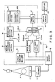
- Fig. 3 is a block diagram of a system for fitting image positions according to the present invention; and
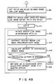
- Figs. 4A and 4B are a flowchart of the operation of the image position fitting system of the present invention.
- Parameters of amounts of shift ΔX and ΔY and an amount of rotation Δϑ are used to position-fit two images having an image of a subject under examination. Hereinafter a description will be made of a case where two digital images are position-fit with respect to each other which have 1760 × 1760 pixels and a gray level of 10 bits (0 - 1023).
- As shown in Figs. 2A and 2B, regions of interest ROI1a and ROI2a (each of 500 × 500 pixels) are respectively set at the top right-hand corners of two images. Images within the regions of interest are cut out. The cut-out images are subjected to a subtraction process. The entropy E of a subtraction image obtained by the subtraction process is calculated as follows:

- When the amounts of shift ΔX and ΔY are obtained by which the entropy of the subtraction image is made minimum, ROI1b and ROI2b (each of 500 × 500 pixels) are set at the bottom left-hand corners of the images. The images within the regions ROI1b and ROI2b are cut out. The cut-out images are then subjected to subtraction.
- As amounts of shift ΔX and ΔY in the subtraction process, the previously obtained amounts of shift ΔXo and ΔYo are used. The images are rotated by an amount of rotation Δϑ with their centers of rotation at the respective centers of regions ROI1a and ROI2a. Consequently such an amount of rotation Δϑ as to make the entropy of the subtraction image minimum (local minimum in the present embodiment) is searched for.
- To search for the amount of rotation Δϑ, the extremum-search method for one parameter, such as the one-dimensional Newton method, may be used.
- The parameters ΔX, ΔY and Δϑ to make the entropy minimum are searched for in that way. In the case of digital radiography images having a large number of pixels, accordingly, by performing the extremum search two times on regions with a relatively small number of pixels, it becomes possible to fit positions of two images to be subjected to subtraction with respect to each other rapidly and accurately.
- Next, a system for performing the above image position fitting will be described.
- In the system of the present invention shown in Fig. 3, X-rays generated by an X-ray tube 1 are radiated to an imaging plate (IP) 2 through a subject P under examination. The X-ray information recorded on
IP 2 is read by an IP scanner 3. - An image memory 12 stores image information output from IP scanner 3. The image information stored in image memory 12 includes mask images and live images. The mask images are obtained without the use of contrast medium, while the live images are obtained by the use of contrast medium.
- An image
position fitting unit 30 comprises an cutout position setting section 11, amask image buffer 13, a live image buffer 21, asubtraction processing section 16, animage buffer 17, anentropy calculating section 18, aparameter setting section 14 and an affinetransform processing section 15. -
Mask image buffer 13 stores an image (hereinafter referred to as a region mask image) within an region of interest of a mask image, while live image buffer 21 stores an image (hereinafter referred to as a region live image). - Cutout position setting section 11 sets regions of interest at the top right-hand corner and bottom left-hand corner of an image stored in image memory 12 as the cutout positions of the image.
-
Parameter setting section 14 stores extremum-search algorithms according to the above one-dimensional and two-dimensional Newton methods and sets the position fitting parameters, i.e., amounts of shift ΔX and ΔY and an amount of rotation Δϑ in accordance with the entropy E calculated byentropy calculating section 18 using the stored extremum-search algorithms. Δϑ is a rotation angle with their rotation centers at the respective centers of ROI1a and ROI2a. - Affine
transform processing section 15 calculates the position of image data according to the parameters ΔX, ΔY and Δϑ. -
Subtraction processing section 16 performs subtraction process on two images on the basis of a region mask image Qmask stored inmask image buffer 13, a region live image Qlive stored in live image buffer 21 and parameters ΔX, ΔY and Δϑ set byparameter setting section 14. -
Image buffer 17 stores a subtraction image obtained insubtraction processing section 16. -
Entropy calculating section 18 calculates the entropy of the subtraction image transferred fromsubtraction processing section 16 viaimage buffer 17. - When the search for the subtraction position is completed, the subtraction image stored in
image buffer 17 is displayed on adisplay 20 via adisplay memory 19. - The search for the subtraction position is completed when a
checking section 18a ofentropy calculating section 18 determines the entropy of the subtraction image to be minimum. - Next, the operation of the system will be described with reference to Figs. 4A and 4B.
- In step S1, regions of interest ROI1a and ROI2a are set, respectively, at the top right-hand corner of a mask image and the top left-hand corner of a live image stored in image memory 12 by cutout position setting section 11. In step S2, a region mask image within ROI1a is read out from image memory 12 and entered into
subtraction processing section 16 viamask image buffer 13. Also, a region live image within ROI2a is read out from image memory 12 and entered intosubtraction processing section 16 via live image buffer 21. - In step S3, initial values of position fitting parameters ΔX and ΔY are set to 0 in
parameter setting section 14. - In affine
transform processing section 15, the position of image data is calculated according to the position fitting parameters ΔX and ΔY and then entered intosubtraction processing section 16 viamask image buffer 13. At this point, for example, the movement position of the region live image is calculated and the region live image is moved (step S4). - Assuming that subtraction parameters A, B and C set by
parameter setting section 14 are 1, -1 and 511, respectively, a subtraction image I of the region mask image and region live image is calculated bysubtraction processing section 16 as follows (step S5):
I = A × Qmask + B × Qlive + C - The subtraction image calculated as above is entered into
entropy calculating section 18 viaimage buffer 17. - In step S6, the entropy of the entered subtraction image is calculated by
entropy calculating section 18. The calculated entropy is then entered intoparameter setting section 14. - In step S7, in checking
section 18a ofentropy calculating section 18, it is determined whether the entered entropy is local minimum or not. - In step S7, when it is determined that the entered entropy is not local minimum, the entropy calculated by
entropy calculating section 18 is entered intoparameter setting section 14. In step S8, the new position fitting parameters ΔX and ΔY are set byparameter setting section 14 on the basis of the entered entropy. The new parameters are then entered into affinetransform processing section 15. - The above steps S4 to S8 are performed repeatedly to determine parameters ΔX and ΔY that make the entropy of the image local minimum.
- In step S7, when it is determined that the entered entropy is local minimum, the parameter Δϑ is determined by the same process as with ROI1a and ROI2a.
- That is, in step S9, regions ROI1b and ROI2b are set at the bottom left-hand corners of the mask and live images. In step S10, a region mask image within ROI1b and a region live image within ROI2b are read out from image memory 12 and then entered into
subtraction processing section 16 viamask image buffer 13 and live mask buffer 21. - In step S11, 0 is set as the initial value of position fitting parameter Δϑ. In step S12, the region live image is rotated according to position fitting parameter Δϑ.
- In step S13, the subtraction process is performed on the region mask image and the rotated region live image.
- In step S14, the entropy of the subtraction image obtained by the subtraction process in step S13 is calculated.
- In step S15, it is determined whether or not the calculated entropy is local minimum. When the calculated entropy is not local minimum, the new position fitting parameter Δϑ is set on the basis of calculated entropy in step S16.
- The above steps S12 to S16 are performed repeatedly to determine the parameter Δϑ that makes the entropy of the image local minimum.
- By determining parameters ΔX, ΔY and Δϑ that make the entropy of the image local minimum in accordance with the above processes, it becomes possible to position-fit two images with respect to each other. It is actually desired that the search for the position in which the entropy of the image is truly minimum. As in the present embodiment, however, the searching for the position in which the entropy of the image is local minimum also allows two images to be position-fit with respect to each other with sufficient accuracy. In addition, in the present invention, there is no need for position-fitting of the overall regions of images, thus saving process time considerably.
- Moreover, the present invention permits the position-fitting of three or more images.
- Although only one embodiment of the present invention has been disclosed and described, it is apparent that other embodiments and modifications of the invention are possible.
Claims (10)
acquiring a plurality of images;
setting a plurality of regions on each acquired image;
cutting out a plurality of region images within the set regions;
setting position fitting parameters;
moving at least one region image outside a standard region image selected from the region images in accordance with the set position fitting parameters;
subtracting the moved region image from the standard region image, thereby obtaining a subtraction image;
calculating an entropy of the subtraction image; and
fitting the image positions among the acquired images in accordance with the set position fitting parameters, when the calculated entropy reaches minimum.
acquiring means (1, 2, 3, 12) for acquiring a plurality of images;
region setting means (11) for setting a plurality of regions on each acquired image;
cutting out means for (11) cutting out a plurality of region images within the set regions;
parameter setting means (14) for setting position fitting parameters;
moving means (15) for moving at least one region image outside a standard region image selected from the region images in accordance with the set position fitting parameters;
subtracting means (16) for subtracting the moved region image from the standard region image, thereby obtaining a subtraction image;
entropy calculating means (18) for calculating an entropy of the subtraction image; and
fitting means (14, 15, 18) for fitting the image positions among the acquired images in accordance with the set position fitting parameters, when the calculated entropy reaches minimum.
Applications Claiming Priority (2)
| Application Number | Priority Date | Filing Date | Title |
|---|---|---|---|
| JP63252977A JPH02100583A (en) | 1988-10-07 | 1988-10-07 | Method and device for aligning picture |
| JP252977/88 | 1988-10-07 |
Publications (3)
| Publication Number | Publication Date |
|---|---|
| EP0362849A2 true EP0362849A2 (en) | 1990-04-11 |
| EP0362849A3 EP0362849A3 (en) | 1991-08-21 |
| EP0362849B1 EP0362849B1 (en) | 1996-12-11 |
Family
ID=17244787
Family Applications (1)
| Application Number | Title | Priority Date | Filing Date |
|---|---|---|---|
| EP89118507A Expired - Lifetime EP0362849B1 (en) | 1988-10-07 | 1989-10-05 | Method and system for fitting image positions |
Country Status (4)
| Country | Link |
|---|---|
| US (1) | US5034988A (en) |
| EP (1) | EP0362849B1 (en) |
| JP (1) | JPH02100583A (en) |
| DE (1) | DE68927545T2 (en) |
Cited By (4)
| Publication number | Priority date | Publication date | Assignee | Title |
|---|---|---|---|---|
| WO1995026539A1 (en) * | 1994-03-25 | 1995-10-05 | Idt International Digital Technologies Deutschland Gmbh | Method and apparatus for estimating motion |
| GB2331440A (en) * | 1997-11-15 | 1999-05-19 | Elekta Ab | Analysis of radiographic images |
| WO2006015971A1 (en) * | 2004-08-09 | 2006-02-16 | Bracco Research Sa | An image registration method and apparatus for medical imaging based on mulptiple masks |
| WO2011001328A1 (en) * | 2009-06-30 | 2011-01-06 | Koninklijke Philips Electronics N.V. | Digital image subtraction |
Families Citing this family (11)
| Publication number | Priority date | Publication date | Assignee | Title |
|---|---|---|---|---|
| US5485371A (en) * | 1990-02-14 | 1996-01-16 | Fuji Photo Film Co., Ltd. | Method for forming energy subtraction radiation images, and method and apparatus for smoothing radiation images |
| US5384861A (en) * | 1991-06-24 | 1995-01-24 | Picker International, Inc. | Multi-parameter image display with real time interpolation |
| JPH06259541A (en) * | 1992-10-30 | 1994-09-16 | Toshiba Corp | Method for correcting image distorting and its system |
| US8630498B2 (en) * | 2006-03-02 | 2014-01-14 | Sharp Laboratories Of America, Inc. | Methods and systems for detecting pictorial regions in digital images |
| US7792359B2 (en) | 2006-03-02 | 2010-09-07 | Sharp Laboratories Of America, Inc. | Methods and systems for detecting regions in digital images |
| US7889932B2 (en) * | 2006-03-02 | 2011-02-15 | Sharp Laboratories Of America, Inc. | Methods and systems for detecting regions in digital images |
| US7864365B2 (en) * | 2006-06-15 | 2011-01-04 | Sharp Laboratories Of America, Inc. | Methods and systems for segmenting a digital image into regions |
| US8437054B2 (en) * | 2006-06-15 | 2013-05-07 | Sharp Laboratories Of America, Inc. | Methods and systems for identifying regions of substantially uniform color in a digital image |
| US7876959B2 (en) * | 2006-09-06 | 2011-01-25 | Sharp Laboratories Of America, Inc. | Methods and systems for identifying text in digital images |
| US20090041344A1 (en) * | 2007-08-08 | 2009-02-12 | Richard John Campbell | Methods and Systems for Determining a Background Color in a Digital Image |
| JP5511152B2 (en) * | 2008-05-14 | 2014-06-04 | 富士フイルム株式会社 | Energy subtraction method and apparatus |
Citations (3)
| Publication number | Priority date | Publication date | Assignee | Title |
|---|---|---|---|---|
| JPS5899082A (en) * | 1981-12-09 | 1983-06-13 | Hitachi Medical Corp | Subtraction picture processor |
| JPS5980085A (en) * | 1982-10-30 | 1984-05-09 | Shimadzu Corp | Digital subtraction system |
| JPH0241077A (en) * | 1988-07-30 | 1990-02-09 | Shimadzu Corp | Dsa equipment |
Family Cites Families (8)
| Publication number | Priority date | Publication date | Assignee | Title |
|---|---|---|---|---|
| US4736437A (en) * | 1982-11-22 | 1988-04-05 | View Engineering, Inc. | High speed pattern recognizer |
| JPS59137942A (en) * | 1983-01-28 | 1984-08-08 | Hitachi Ltd | Picture positioning system |
| IL69327A (en) * | 1983-07-26 | 1986-11-30 | Elscint Ltd | Automatic misregistration correction |
| JP2531605B2 (en) * | 1984-02-24 | 1996-09-04 | 株式会社東芝 | Image registration device |
| JPS62122635A (en) * | 1985-11-22 | 1987-06-03 | 株式会社東芝 | Radiation image treatment apparatus |
| US4769756A (en) * | 1986-08-07 | 1988-09-06 | The United States Of America As Represented By The Department Of Health And Human Services | Systematic method for matching existing radiographic projections with radiographs to be produced from a specified region of interest in cancellous bone |
| NL8603059A (en) * | 1986-12-01 | 1988-07-01 | Philips Nv | DEVICE AND METHOD WITH MOTION ARTEFACT REDUCTION FOR DIFFERENCE IMAGE DETERMINATION. |
| US4872188A (en) * | 1987-11-27 | 1989-10-03 | Picker International, Inc. | Registration correction for radiographic scanners with sandwich detectors |
-
1988
- 1988-10-07 JP JP63252977A patent/JPH02100583A/en active Granted
-
1989
- 1989-10-03 US US07/416,040 patent/US5034988A/en not_active Expired - Fee Related
- 1989-10-05 DE DE68927545T patent/DE68927545T2/en not_active Expired - Fee Related
- 1989-10-05 EP EP89118507A patent/EP0362849B1/en not_active Expired - Lifetime
Patent Citations (3)
| Publication number | Priority date | Publication date | Assignee | Title |
|---|---|---|---|---|
| JPS5899082A (en) * | 1981-12-09 | 1983-06-13 | Hitachi Medical Corp | Subtraction picture processor |
| JPS5980085A (en) * | 1982-10-30 | 1984-05-09 | Shimadzu Corp | Digital subtraction system |
| JPH0241077A (en) * | 1988-07-30 | 1990-02-09 | Shimadzu Corp | Dsa equipment |
Non-Patent Citations (4)
| Title |
|---|
| §§TENT ABSTACTS OF JAPAN, vol. 7, no. 200 (E-196)[1345], 3rd September 1983; & JP-A-58 099 082 (HTACHI) 13-06-1983 * |
| PATENT ABSTACTS OF JAPAN, vol. 7, no. 200 (E-196)[1345], 3rd September 1983; & JP-A-58 99 082 (HTACHI) 13-06-1983 * |
| PATENT ABSTRACTS OF JAPAN, vol. 14, no. 200 (E-920)[4143], 24th April 1990; & JP-A-02 041 077 (SHIMADZU) 09-02-1990 * |
| PATENT ABSTRACTS OF JAPAN, vol. 8, no. 190 (E-263)[1627], 31st August 1984; & JP-A-59 080 085 (SHIMAZU) 09-05-1984 * |
Cited By (10)
| Publication number | Priority date | Publication date | Assignee | Title |
|---|---|---|---|---|
| WO1995026539A1 (en) * | 1994-03-25 | 1995-10-05 | Idt International Digital Technologies Deutschland Gmbh | Method and apparatus for estimating motion |
| GB2331440A (en) * | 1997-11-15 | 1999-05-19 | Elekta Ab | Analysis of radiographic images |
| GB2331440B (en) * | 1997-11-15 | 2001-08-29 | Elekta Ab | Analysis of radiographic images |
| US6333991B1 (en) | 1997-11-15 | 2001-12-25 | Elekta Ab | Analysis of radiographic images |
| WO2006015971A1 (en) * | 2004-08-09 | 2006-02-16 | Bracco Research Sa | An image registration method and apparatus for medical imaging based on mulptiple masks |
| US7912259B2 (en) | 2004-08-09 | 2011-03-22 | Bracco International Bv | Image registration method and apparatus for medical imaging based on multiple masks |
| WO2011001328A1 (en) * | 2009-06-30 | 2011-01-06 | Koninklijke Philips Electronics N.V. | Digital image subtraction |
| CN102473296A (en) * | 2009-06-30 | 2012-05-23 | 皇家飞利浦电子股份有限公司 | Digital image subtraction |
| CN102473296B (en) * | 2009-06-30 | 2016-01-20 | 皇家飞利浦电子股份有限公司 | digital image subtraction |
| US9251576B2 (en) | 2009-06-30 | 2016-02-02 | Koninklijke Philips N.V. | Digital image subtraction |
Also Published As
| Publication number | Publication date |
|---|---|
| JPH02100583A (en) | 1990-04-12 |
| DE68927545D1 (en) | 1997-01-23 |
| EP0362849A3 (en) | 1991-08-21 |
| US5034988A (en) | 1991-07-23 |
| JPH0479190B2 (en) | 1992-12-15 |
| EP0362849B1 (en) | 1996-12-11 |
| DE68927545T2 (en) | 1997-07-10 |
Similar Documents
| Publication | Publication Date | Title |
|---|---|---|
| EP0362849A2 (en) | Method and system for fitting image positions | |
| US5896463A (en) | Method and apparatus for automatically locating a region of interest in a radiograph | |
| US4229797A (en) | Method and system for whole picture image processing | |
| JP3683914B2 (en) | Multiprocessing method of radiological images based on pyramidal image decomposition | |
| USRE42881E1 (en) | Method and system for scanning images in a photo kiosk | |
| US5956435A (en) | Automatic analysis of two different images of the same object | |
| US5008947A (en) | Method and apparatus for correcting extension rates of images | |
| US5042077A (en) | Method of highlighting subtle contrast in graphical images | |
| EP0653726B1 (en) | A technique for finding the histogram region of interest for improved tone scale reproduction of digital radiographic images | |
| EP1008956A1 (en) | Automatic image montage system | |
| US20090110285A1 (en) | Apparatus and method for improving image resolution using fuzzy motion estimation | |
| KR19990067567A (en) | Vector Correlation System for Automatic Positioning of Patterns in Images | |
| EP0136652B1 (en) | Image processing apparatus with automatic window processing function | |
| US6868172B2 (en) | Method for registering images in a radiography application | |
| US7035450B1 (en) | Method for locating an element of interest contained in a three-dimensional object, in particular during a stereotactic investigation in the X-ray examination of the breast | |
| JPH07153592A (en) | Operation of automatic x-ray exposure device and automatic x-ray exposure device | |
| US6356652B1 (en) | Visualization of diagnostically irrelevant zones in a radiographic image | |
| JPH06290276A (en) | Arrangement and method for visualization of three-dimensional scene | |
| JP2000316837A (en) | Imaging diagnosis aid device | |
| US6480619B1 (en) | Method of displaying part of a radiographic image | |
| EP0094597A2 (en) | Image processing for unsharp masking of image | |
| EP0132795B1 (en) | Method and apparatus for image processing with field portions | |
| JPH08110939A (en) | Picture aligning processor and inter-picture arithmetic processing unit | |
| JP2002063563A (en) | Method and system for image processing | |
| US7043067B2 (en) | Blackening processing method and apparatus for radiation images |
Legal Events
| Date | Code | Title | Description |
|---|---|---|---|
| PUAI | Public reference made under article 153(3) epc to a published international application that has entered the european phase |
Free format text: ORIGINAL CODE: 0009012 |
|
| 17P | Request for examination filed |
Effective date: 19891005 |
|
| AK | Designated contracting states |
Kind code of ref document: A2 Designated state(s): DE NL |
|
| PUAL | Search report despatched |
Free format text: ORIGINAL CODE: 0009013 |
|
| AK | Designated contracting states |
Kind code of ref document: A3 Designated state(s): DE NL |
|
| 17Q | First examination report despatched |
Effective date: 19941107 |
|
| GRAG | Despatch of communication of intention to grant |
Free format text: ORIGINAL CODE: EPIDOS AGRA |
|
| GRAH | Despatch of communication of intention to grant a patent |
Free format text: ORIGINAL CODE: EPIDOS IGRA |
|
| GRAH | Despatch of communication of intention to grant a patent |
Free format text: ORIGINAL CODE: EPIDOS IGRA |
|
| GRAA | (expected) grant |
Free format text: ORIGINAL CODE: 0009210 |
|
| AK | Designated contracting states |
Kind code of ref document: B1 Designated state(s): DE NL |
|
| REF | Corresponds to: |
Ref document number: 68927545 Country of ref document: DE Date of ref document: 19970123 |
|
| PLBE | No opposition filed within time limit |
Free format text: ORIGINAL CODE: 0009261 |
|
| STAA | Information on the status of an ep patent application or granted ep patent |
Free format text: STATUS: NO OPPOSITION FILED WITHIN TIME LIMIT |
|
| 26N | No opposition filed | ||
| PGFP | Annual fee paid to national office [announced via postgrant information from national office to epo] |
Ref country code: DE Payment date: 19981012 Year of fee payment: 10 |
|
| PGFP | Annual fee paid to national office [announced via postgrant information from national office to epo] |
Ref country code: NL Payment date: 19981028 Year of fee payment: 10 |
|
| PG25 | Lapsed in a contracting state [announced via postgrant information from national office to epo] |
Ref country code: NL Free format text: LAPSE BECAUSE OF NON-PAYMENT OF DUE FEES Effective date: 20000501 |
|
| NLV4 | Nl: lapsed or anulled due to non-payment of the annual fee |
Effective date: 20000501 |
|
| PG25 | Lapsed in a contracting state [announced via postgrant information from national office to epo] |
Ref country code: DE Free format text: LAPSE BECAUSE OF NON-PAYMENT OF DUE FEES Effective date: 20000801 |