EP0362208B1 - Optisches koppelelement - Google Patents
Optisches koppelelement Download PDFInfo
- Publication number
- EP0362208B1 EP0362208B1 EP88902875A EP88902875A EP0362208B1 EP 0362208 B1 EP0362208 B1 EP 0362208B1 EP 88902875 A EP88902875 A EP 88902875A EP 88902875 A EP88902875 A EP 88902875A EP 0362208 B1 EP0362208 B1 EP 0362208B1
- Authority
- EP
- European Patent Office
- Prior art keywords
- optical
- fibre
- pick
- rod
- optical fibre
- Prior art date
- Legal status (The legal status is an assumption and is not a legal conclusion. Google has not performed a legal analysis and makes no representation as to the accuracy of the status listed.)
- Expired - Lifetime
Links
- 230000003287 optical effect Effects 0.000 title claims abstract description 50
- 230000008878 coupling Effects 0.000 title claims abstract description 30
- 238000010168 coupling process Methods 0.000 title claims abstract description 30
- 238000005859 coupling reaction Methods 0.000 title claims abstract description 30
- 239000013307 optical fiber Substances 0.000 claims abstract description 40
- 230000005855 radiation Effects 0.000 claims abstract description 33
- 239000011248 coating agent Substances 0.000 claims abstract description 13
- 238000000576 coating method Methods 0.000 claims abstract description 13
- 239000004033 plastic Substances 0.000 claims abstract description 6
- 229920003023 plastic Polymers 0.000 claims abstract description 6
- 239000000463 material Substances 0.000 claims description 17
- 239000000835 fiber Substances 0.000 abstract description 67
- VYPSYNLAJGMNEJ-UHFFFAOYSA-N Silicium dioxide Chemical compound O=[Si]=O VYPSYNLAJGMNEJ-UHFFFAOYSA-N 0.000 abstract description 12
- 238000004891 communication Methods 0.000 abstract description 10
- 239000000377 silicon dioxide Substances 0.000 abstract description 6
- 238000012423 maintenance Methods 0.000 abstract description 2
- 238000005253 cladding Methods 0.000 description 8
- 230000001681 protective effect Effects 0.000 description 4
- 238000012360 testing method Methods 0.000 description 4
- 230000005540 biological transmission Effects 0.000 description 3
- 238000013461 design Methods 0.000 description 3
- 239000011521 glass Substances 0.000 description 3
- 238000009826 distribution Methods 0.000 description 2
- 238000000034 method Methods 0.000 description 2
- 238000005498 polishing Methods 0.000 description 2
- 238000002360 preparation method Methods 0.000 description 2
- 239000004677 Nylon Substances 0.000 description 1
- 238000005452 bending Methods 0.000 description 1
- 230000003247 decreasing effect Effects 0.000 description 1
- 230000000593 degrading effect Effects 0.000 description 1
- 230000001419 dependent effect Effects 0.000 description 1
- 239000003989 dielectric material Substances 0.000 description 1
- 230000000694 effects Effects 0.000 description 1
- 238000005516 engineering process Methods 0.000 description 1
- 239000012530 fluid Substances 0.000 description 1
- 238000004519 manufacturing process Methods 0.000 description 1
- 229920001778 nylon Polymers 0.000 description 1
- 239000006223 plastic coating Substances 0.000 description 1
- 229920000642 polymer Polymers 0.000 description 1
- 239000011253 protective coating Substances 0.000 description 1
- 230000035945 sensitivity Effects 0.000 description 1
- 238000000926 separation method Methods 0.000 description 1
- 239000007787 solid Substances 0.000 description 1
- 238000011282 treatment Methods 0.000 description 1
Images

Classifications
-
- G—PHYSICS
- G02—OPTICS
- G02B—OPTICAL ELEMENTS, SYSTEMS OR APPARATUS
- G02B6/00—Light guides; Structural details of arrangements comprising light guides and other optical elements, e.g. couplings
- G02B6/10—Light guides; Structural details of arrangements comprising light guides and other optical elements, e.g. couplings of the optical waveguide type
- G02B6/14—Mode converters
-
- G—PHYSICS
- G02—OPTICS
- G02B—OPTICAL ELEMENTS, SYSTEMS OR APPARATUS
- G02B6/00—Light guides; Structural details of arrangements comprising light guides and other optical elements, e.g. couplings
- G02B6/24—Coupling light guides
- G02B6/42—Coupling light guides with opto-electronic elements
- G02B6/4201—Packages, e.g. shape, construction, internal or external details
- G02B6/4286—Optical modules with optical power monitoring
-
- G—PHYSICS
- G02—OPTICS
- G02B—OPTICAL ELEMENTS, SYSTEMS OR APPARATUS
- G02B6/00—Light guides; Structural details of arrangements comprising light guides and other optical elements, e.g. couplings
- G02B6/24—Coupling light guides
- G02B6/42—Coupling light guides with opto-electronic elements
- G02B6/4201—Packages, e.g. shape, construction, internal or external details
- G02B6/4287—Optical modules with tapping or launching means through the surface of the waveguide
- G02B6/4289—Optical modules with tapping or launching means through the surface of the waveguide by inducing bending, microbending or macrobending, to the light guide
Definitions
- the present invention relates to optical coupling devices. It finds particular application in maintenance, or fault finding, in optical communications systems.
- this technique for injecting and picking off light has the advantage that little preparation of the fibre has to be done, that is, it can be carried out for instance through a protective polymer coating carried by a fibre, there are circumstances in which it is unsuitable.
- the technique injects a relatively high power level of light and picks off as high a proportion of the light injected as possible.
- Optical couplers are known which can be used to couple an adjustable power level of light into, or from, an optical fibre, but they rely on careful preparation of the fibre. For instance, in one type, the core glass of the fibre has to be brought close to the fibre surface by mounting the fibre in a curved position and polishing away the cladding glass on the outside of the curve until fibre core glass is almost exposed. Light is then coupled into, and out of, the exposed core of the fibre by controlling the relative position of a second fibre which has been polished in the same manner.
- Optical couplers of this type suffer from the disadvantages that they are time-consuming and expensive to produce.
- a monomode fibre typically has an outer diameter of 125 ⁇ m and a core diameter of only 9 ⁇ m. Hence, it is difficult to control the polishing steps with sufficient accuracy.
- the couplers are also limited in that they can only be used at predetermined fixed positions along a prepared fibre. Furthermore, the arrangement tends to be vulnerable and unsuitable for use in the field.
- optical coupler Another known type of optical coupler is described in GB-A-2 126 749.
- this coupler light guided by an optical fibre is tapped to a detector by substantially surrounding a portion of the fibre with a tube and by bending the fibre and the tube.
- the tube couples a portion of the optical energy carried by the fibre to the detector.
- the aim of the invention is to provide an optical coupling device which can conveniently be used to test optical fibres in use in an optical communications system.
- the present invention provides an optical coupling device for coupling low power levels of optical radiation out of an optical fibre having a primary coating of plastics material and a refractive index of n1 at or near its surface, the coupling device comprising a pick-up element having a refractive index n3 and providing a curved optical waveguiding path therein, and retaining means for retaining the optical fibre in a curved position which at least substantially conforms to the inner surface of the curved path, the refractive indices of the pick-up element and the surface of the optical fibre, n3 and n1, and the radius of curvature, R, in mm of the inner surface of the curved path portion of the pick-up element being chosen such that n3>n1 (1-0.125/R), R being greater than or equal to 3, characterised in that the retaining means is constituted by a clamping means comprising a block of material having a convex surface, a groove being provided in the convex surface to locate the optical waveguide over the convex surface,
- the clamping means is movable relative to the pick-up element.
- a waveguiding path in this context is intended to mean a path along which optical radiation will be guided by means of the distribution of refractive index in the materials of the waveguiding path.
- a waveguiding path will comprise, in cross-section, a core region of one refractive index, surrounded by a cladding region of a lower refractive index or range of refractive index.
- the refractive index of the material of the path should preferably be greater than that of the optical fibre.
- the pick-up element comprises a solid curved rod of a dielectric material such as silica.
- the radiation from a curved optical fibre does not leak away uniformly with distance along the fibre, but in a series of discrete, well-defined, tangential beams. These beams form a divergent pattern, angular separation of the beams being a function of bend radius of the fibre. Both the bend radius and the length of the curved optical fibre which is curved are factors which affect the power level of optical radiation coupled out of the optical fibre.
- a suitable radius of curvature of a fibre to couple out sufficient power for testing purposes without significantly degrading transmission has been found to be of the order of 15mm, the total length of curved fibre subtending an angle of about 120°. Using such an arrangement, the loss introduced to the system may be of the order of only 3dB.
- devices according to embodiments of the present invention can couple power levels of optical radiation out of an optical fibre which has a primary protective plastic coating intact as low as about 1nW.
- typically the power level of the optical radiation coupled out of a fibre should be less than or equal to 50% of the average power level of optical radiation being transmitted by the fibre.
- a coupling device may conveniently be applied to an optical fibre at a point in a communications system where the primary coating of the fibre is exposed for routing purposes. For instance, this is generally the case in joint housings, and at distribution points.
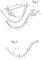
- the optical coupling device comprises a silica rod 1 having a curved and a straight portion, and a block 2, which co-operate to clamp an optical fibre 3 against the inner surface 4 of the curved portion of rod 1.
- Optical radiation which leaks out of the clamped optical fibre 3 in use is than picked up by the curved portion of rod 1 and guided to a photodetector 6 to be converted to an output signal.
- the curved portion of the rod is followed by an extended straight portion against which the fibre is also clamped.
- an extended straight portion against which the fibre is also clamped is shown in Figure 1a.
- the angle ⁇ ° is 30°
- the lengths L and M are each 20mm
- the radius R is between 3 and 11mm.
- the rod 1 has a square cross section with sides of 2mm.
- the curved portion has a substantially constant radius of curvature R (to the inner surface 4) of 8mm, and subtends an angle of 160° at its centre of curvature.
- the end of the rod 1 adjacent the curved portion is polished to give a smooth finish.
- a convenient method of making the rod 1 is to cut a 2mm annular length from the end of a silica tube, the tube having a 16mm internal diameter, and 2mm wall thickness. Each flat end face of the annular length is polished and a segment then removed, to leave a C-shaped portion. One end of the C-shaped portion is then straightened outwards to form the straight portion of the rod 1.
- the photodetector 6 Mounted on the end of the rod 1 adjacent the straight portion is the photodetector 6. Devices suitable for use in detecting light in these circumstances are known and further details are not therefore given. Clearly it will be necessary, however, that whatever is used to detect the light must be capable of responding to optical power levels as low as those which will be encountered in use of the coupling device.
- the block 2 comprises an optically opaque plastics material and has a side elevation which is substantially D-shaped. It is flat-sided and has a thickness of about 20mm.
- the major part of the curved surface 7 is curved to match the shape of the inner surface 4 of the curved portion of the rod 1.
- the length of the curved surface 7 is greater than that of the rod's inner surface 4, however, so that when the coupling device is assembled, as shown in Figure 1, the block 2 protrudes from the curved portion of the rod 1.
- the curved surface 7 of the block 2 is provided with a central, V-profile groove 8.
- the groove 8 is 0.1mm deep and its sides meet at 60°. This allows it to locate a monomode optical fibre 3 which has its primary protective plastics material coating in place, the fibre 3 projecting slightly from the groove 8.
- a monomode optical fibre 3 which has its primary protective plastics material coating in place, the fibre 3 projecting slightly from the groove 8.
- Means are provided (not shown) for holding the block 2 and rod 1 together so that a fibre 3 located in the groove 8 is brought into contact with the inner surface 4 of the curved portion of rod 1.
- a simple, spring clip device or the like is suitable for holding the block 2 and rod 1 together, the force exerted by the device being sufficient to retain the coupling device in an assembled position without causing damage to the protective plastics material coating of the fibre 3.
- the block 2 and rod 1 may be pivotally coupled together so than an optical fibre 3 may be gripped between them as in a pair of pliers.
- the output 9 from the photodetector 6 may be coupled to any equipment which it is intended should respond to it.
- this may be a simple indicator, such as a light emitting diode, to show whether or not optical data is being transmitted by the fibre 3 under test.
- a fibre 3 to be tested is placed between the block 2 and the curved rod 1, lying in the groove 8 of the block 2.
- the fibre 3 is gripped sufficiently tightly to distort the primary coating slightly, into the groove 8 and against the rod 1. Because the fibre protrudes from the groove 8, the curved rod 1 is held away from the block 2 by the fibre 3.
- the refractive index of the material of the rod is 1.49.
- the silica rod 1 together they constitute a core region of one refractive index (the silica rod 1) surrounded by cladding regions of a lower refractive index (the air). Because the difference in refractive indexes of the two regions is relatively high, 0.49, the rod 1 is strongly waveguiding and acts to "capture" a significant proportion of the optical radiation which might be leaked from the fibre 3.
- an index matching material such as a fluid or gel, to couple the optical radiation out of the fibre 3 into the rod 1.
- the block 2 acts an an optical seal. It acts to reduce the amount of extraneous radiation, not carried by the fibre 3, which might enter the rod 1 and affect the response of the photodetector 6.
- the upper limit given for n3 by relationship i) is designed to allow the radiation picked up by the rod 1 to exit to the photodetector 6 rather than be reflected at the end of the rod 1. Use of an index matching material between the rod end and the detector or whatever is at the end of the rod may enable this limit to be exceeded.
- the lower limit given by relationship ii), in combination with the t,R relationship iii), is designed to cause internal reflection of radiation picked up by the rod 1 at the outer side of the curved portion of rod 1, thus preventing too significant losses from the rod 1.
- each of the relationships i) to iii) is given for a rod 1 surrounded by air. If the optical fibre 3 is a monomode fibre of the type commonly in use today in optical communications, then the refractive index n1 will have the value 1.456.
- the second two relationships in particular, designed to reduce losses at the outer side of the curved portion of rod 1, are calculated with regard to radiation leaving the optical fibre 3 tangentially and are not intended as strict mathematical treatments of the design limits of a design coupler as described.
- the refractive index of the primary coating should lie between that of the fibre cladding, n1, and that of the rod 1, n3.
- the rod 1 may have a circular, or other rounded, cross section.
- some larger structure which has a curved waveguiding path embedded therein.
- this might have the advantage that it would then be possible to mount the block 2 directly into a structure by means of, for instance, a snap fitting. In this way, the need for independent means to hold the rod 1 and block 2 together would be avoided.
- the structure used could enable the fibre in an assembled coupling device to be protected from damage.
- two photodetectors may be used, for instance one being mounted at each end of the rod 1. This introduces directivity, useful if the fibre 3 concerned is carrying duplex transmissions, or could be used to improve sensitivity by cancelling background effects.
- the curved portion of the rod 1 subtends an angle of 160° at the centre of curvature
- this angle can be varied. For instance it might be reduced to 60° or increased to 180°. However, if it is reduced too much, the device tends to become insensitive in that either sufficient light can not be leaked from the fibre 3 for the photodetector 6 to distinguish or the amount leaked has to be leaked over such a short distance that the losses from the fibre 3 are difficult to predict. If the angle were to be increased beyond 180°, the device becomes physically more difficult to apply to a fibre.
- the curved portion of rod 1, or other curved, optical waveguiding path should conform to part of a circle. That is, the associated radius of curvature does not have to be constant. If it is not, then the angle between the normals to the curved path, at each end of that path, should preferably meet at an angle which lies in the range from 60° to 180° inclusive, more preferably from 90° to 180° inclusive.
- a coupling device may alternatively be used with a fibre having a further secondary coating in place, for instance of nylon or other material, as used in optical fibre cable technology for additional protection.
Landscapes
- Physics & Mathematics (AREA)
- General Physics & Mathematics (AREA)
- Optics & Photonics (AREA)
- Optical Couplings Of Light Guides (AREA)
Claims (11)
- Optische Kopplungsvorrichtung zum Auskoppeln niedriger Leistungspegel optischer Strahlung aus einer optischen Faser (3), die einen Refraktionsindex von n₁ bei oder nahe ihrer Oberfläche hat, und die eine Primärbeschichtung aus Kunststoffmaterial hat, wobei die Kopplungsvorrichtung ein Aufnehmerelement (1) aufweist, das einen Refraktionsindex n₃ hat, wobei das Aufnehmerelement (1) einen Wellenleiterpfad aufweist, von dem zumindest ein Teil gekrümmt ist, um einen gekrümmten optischen Wellenleiterpfad zu bilden, wobei die Kopplungsvorrichtung ebenso eine Rückhalteeinrichtung zum Rückhalten der optischen Faser in einer gekrümmten Position aufweist, die zumindest im wesentlichen mit der inneren Oberfläche (4) des gekrümmten Pfades übereinstimmt, wobei die Refraktionsindizes des Aufnehmerelementes und der Oberfläche der optischen Faser, n₃ und n₁, und der Radius der Krümmung, R, in mm der inneren Oberfläche des gekrümmten Pfadabschnittes des Aufnehmerelementes so gewählt sind, daß n₃ > n₁ (1-0,125/R) ist, wobei R größer als oder gleich 3 ist, dadurch gekennzeichnet, daß die Rückhalteeinrichtung durch eine Klemmeinrichtung gebildet ist, die einen Block (2) aus einem Material aufweist, der eine konvexe Oberfläche hat, wobei eine Nut (8) in der konvexen Oberfläche bereitgestellt ist, um den optischen Wellenleiter (3) über der konvexen Oberfläche anzuordnen, und eine Einrichtung zum Zusammenhalten des Blockes und des Aufnehmerelementes, um die optische Faser in der Nut positioniert zu halten, und wobei die Klemmeinrichtung so ist, um die optische Faser ausreichend fest zu halten, um ihre Primärbeschichtung zu deformieren, so daß bei Verwendung optische Strahlung aus der optischen Faser leckt und in den gekrümmten Pfad gekoppelt wird.
- Vorrichtung gemäß Anspruch 1, worin die Klemmeinrichtung bewegbar relativ zu dem Aufnehmerelement ist.
- Vorrichtung gemäß Anspruch 1 oder 2, worin

- Vorrichtung gemaß einem der Ansprüche 1 bis 3, worin die Dicke des Aufnehmerelementes (1) in mm in der Ebene normal zu der Schnittstelle zwischen dem Aufnehmerelement und der optischen Faser (3) geringer als 0,44R - 0,18 ist.
- Vorrichtung gemäß einem der Ansprüche 1 bis 4, worin das Aufnehmerelement (1) steif und selbsttragend ist.
- Vorrichtung gemäß einem der Ansprüche 1 bis 5, worin das Aufnehmerelement (1) einen optisch transparenten Stab aufweist.
- Vorrichtung gemäß Anspruch 6, worin der Stab (1) einen rechteckigen Querschnitt hat.
- Vorrichtung gemäß einem der Ansprüche 1 bis 7, worin die Normalen zu dem gekrümmten Pfad an dessen jedem Ende sich in einem Winkel treffen, der in dem Bereich von 60° bis 180° liegt.
- Vorrichtung gemäß einem der Ansprüche 1 bis 8, worin der gekrümmte Pfad zumindest einen Abschnitt hat, der einen konstanten Krümmungsradius hat.
- Vorrichtung gemäß einem der Ansprüche 1 bis 9, worin der optische Verlust, der durch die optische Faser (3) eingeführt wird, kleiner oder gleich 6dB ist.
- Vorrichtung gemäß Anspruch 10, worin der optische Verlust, der durch die optische Faser (3) eingeführt wird, kleiner oder gleich 3dB ist.
Priority Applications (1)
| Application Number | Priority Date | Filing Date | Title |
|---|---|---|---|
| AT88902875T ATE99810T1 (de) | 1987-03-24 | 1988-03-24 | Optisches koppelelement. |
Applications Claiming Priority (2)
| Application Number | Priority Date | Filing Date | Title |
|---|---|---|---|
| GB8706929 | 1987-03-24 | ||
| GB878706929A GB8706929D0 (en) | 1987-03-24 | 1987-03-24 | Optical coupling device |
Publications (2)
| Publication Number | Publication Date |
|---|---|
| EP0362208A1 EP0362208A1 (de) | 1990-04-11 |
| EP0362208B1 true EP0362208B1 (de) | 1994-01-05 |
Family
ID=10614498
Family Applications (1)
| Application Number | Title | Priority Date | Filing Date |
|---|---|---|---|
| EP88902875A Expired - Lifetime EP0362208B1 (de) | 1987-03-24 | 1988-03-24 | Optisches koppelelement |
Country Status (6)
| Country | Link |
|---|---|
| US (1) | US4983007A (de) |
| EP (1) | EP0362208B1 (de) |
| AU (1) | AU605856B2 (de) |
| DE (1) | DE3886935T2 (de) |
| GB (2) | GB8706929D0 (de) |
| WO (1) | WO1988007689A1 (de) |
Families Citing this family (33)
| Publication number | Priority date | Publication date | Assignee | Title |
|---|---|---|---|---|
| GB8729951D0 (en) | 1987-12-23 | 1988-02-03 | British Telecomm | Endface assessment |
| GB8800666D0 (en) * | 1988-01-13 | 1988-02-10 | British Telecomm | Optical fibre handling apparatus |
| AU609253B2 (en) * | 1988-01-13 | 1991-04-26 | British Telecommunications Public Limited Company | Optical power meter |
| GB8800667D0 (en) * | 1988-01-13 | 1988-02-10 | British Telecomm | Optical power meter |
| GB2223323B (en) * | 1988-06-04 | 1992-08-12 | Plessey Co Plc | Optical devices using curved, concentric coupled optical waveguides |
| CA1312757C (en) * | 1989-09-27 | 1993-01-19 | Shawn Joseph Morrison | Optical fiber coupling device and method for its use |
| US4961620A (en) * | 1989-12-20 | 1990-10-09 | Raychem Corporation | Optical bypass switch |
| GB9015992D0 (en) * | 1990-07-20 | 1990-09-05 | British Telecomm | Optical tap |
| US5138690A (en) * | 1990-09-28 | 1992-08-11 | Minnesota Mining And Manufacturing Company | Fiber identifier |
| FR2673003B1 (fr) * | 1991-02-15 | 1993-04-23 | Cegelec | Coupleur de piquage optique. |
| US5410628A (en) * | 1991-06-25 | 1995-04-25 | British Telecommunications Public Limited Company | Optical tapping device for use in conjunction with an optical fiber management device |
| DE59303913D1 (de) * | 1992-03-04 | 1996-10-31 | Siemens Ag | Lichtwellenleiter-Signal-Detektor |
| NL9301903A (nl) * | 1993-11-04 | 1995-06-01 | Nederland Ptt | Plaatsonafhankelijke toepassing van een op correlatie gebaseerde OTDR-techniek in een vertakt optische vezel-netwerk in bedrijf. |
| US5483610A (en) * | 1994-12-16 | 1996-01-09 | Minnesota Mining And Manufacturing Company | Clip-on device for optical power meter |
| SE505708C2 (sv) * | 1995-09-11 | 1997-09-29 | Icor Instr Ab | Anordning för överföring av ej parallelliserat ljus från en ljuskälla till en mottagare. |
| FR2769379B1 (fr) * | 1997-10-03 | 2000-02-11 | France Telecom | Dispositif pour l'exploitation et la maintenance des reseaux en fibres optiques |
| DE10108303A1 (de) * | 2001-02-21 | 2002-08-22 | Deutsche Telekom Ag | Anordnung und Verfahren zum Detektieren eines optischen Signals an der Längsseite einer Glasfaser |
| US7386969B2 (en) * | 2003-05-09 | 2008-06-17 | Intellipack | Exterior configuration of a foam-in-bag dispenser assembly |
| US7213383B2 (en) * | 2003-05-09 | 2007-05-08 | Intellipack | Bag forming system edge seal |
| US7735685B2 (en) | 2003-05-09 | 2010-06-15 | Intellipack | Dispensing system with in line chemical pump system |
| US7331542B2 (en) | 2003-05-09 | 2008-02-19 | Intellipack | Film unwind system with hinged spindle and electronic control of web tension |
| US7182221B2 (en) * | 2003-05-09 | 2007-02-27 | Intellipack | Dispensing system and method of manufacturing and using same with a dispenser tip management |
| US7552847B2 (en) * | 2003-05-09 | 2009-06-30 | Intellipack | Dispenser mixing module and method of assembling and using same |
| US7156260B2 (en) * | 2003-05-09 | 2007-01-02 | Intellipack | Mixing module drive mechanism and dispensing system with same |
| US7341632B2 (en) * | 2003-05-09 | 2008-03-11 | Intellipack | Dispensing system with means for easy access of dispenser components and method of using same |
| US7610113B2 (en) * | 2003-05-09 | 2009-10-27 | Intellipack, Inc. | Operational control system and a system providing for remote monitoring of a manufacturing device |
| US8124915B2 (en) * | 2003-05-09 | 2012-02-28 | Pregis Intellipack Corporation | Sealing device |
| JP5164271B2 (ja) * | 2008-06-24 | 2013-03-21 | 株式会社フジクラ | 光コネクタの接続確認方法および接続確認装置 |
| US9097524B2 (en) | 2009-09-11 | 2015-08-04 | Invensense, Inc. | MEMS device with improved spring system |
| US8534127B2 (en) * | 2009-09-11 | 2013-09-17 | Invensense, Inc. | Extension-mode angular velocity sensor |
| US10024656B2 (en) | 2015-04-29 | 2018-07-17 | Honeywell International Inc. | System and methods for highly integrated optical readout MEMS sensors |
| US9803979B2 (en) * | 2015-06-26 | 2017-10-31 | Honeywell International Inc. | Systems and methods for a time-based optical pickoff for MEMS sensors |
| CN109387167A (zh) * | 2018-12-04 | 2019-02-26 | 上海润京能源科技有限公司 | 一种光纤切割面检测装置及检测方法 |
Citations (1)
| Publication number | Priority date | Publication date | Assignee | Title |
|---|---|---|---|---|
| GB2126749A (en) * | 1982-09-09 | 1984-03-28 | Western Electric Co | Optical fiber tap |
Family Cites Families (25)
| Publication number | Priority date | Publication date | Assignee | Title |
|---|---|---|---|---|
| JPS5612184B2 (de) * | 1973-10-23 | 1981-03-19 | ||
| JPS50100122A (de) * | 1973-12-26 | 1975-08-08 | ||
| US3910677A (en) * | 1974-05-13 | 1975-10-07 | Bell Telephone Labor Inc | Hyperbolic type optical fiber lens coupler for coupling the fiber to an optical line source |
| GB1538195A (en) * | 1974-11-08 | 1979-01-10 | Plessey Co Ltd | Method and apparatus for detecting light radiated from or propogating light into optical fibres |
| US3936631A (en) * | 1974-11-11 | 1976-02-03 | Bell Telephone Laboratories, Incorporated | Optical fiber power tap |
| US3931518A (en) * | 1974-11-11 | 1976-01-06 | Bell Telephone Laboratories, Incorporated | Optical fiber power taps employing mode coupling means |
| JPS51149822A (en) * | 1975-06-19 | 1976-12-23 | Nippon Kokan Tsugite Kk | Method and device for regenerating casting sand |
| JPS5359821A (en) * | 1976-11-10 | 1978-05-30 | Mitsubishi Electric Corp | Bipolar current transformer |
| DE2841133A1 (de) * | 1978-09-21 | 1980-04-03 | Siemens Ag | Abzweigelement |
| DE2942664A1 (de) * | 1979-10-23 | 1981-05-07 | Licentia Patent-Verwaltungs-Gmbh, 6000 Frankfurt | Verfahren zur herstellung eines optischen strahlteilers |
| DE3011663A1 (de) * | 1980-03-26 | 1981-10-01 | Licentia Patent-Verwaltungs-Gmbh, 6000 Frankfurt | Polarisator fuer faseroptische anordnungen |
| AU551638B2 (en) * | 1981-04-27 | 1986-05-08 | Raychem Corporation | Optical fibre alignment |
| US4436365A (en) * | 1981-10-21 | 1984-03-13 | Bell Telephone Laboratories, Incorporated | Data link using integrated optics devices |
| US4557552A (en) * | 1981-11-19 | 1985-12-10 | Board Of Trustees Of The Leland Stanford Junior University | Microbend optical fiber tapped delay line |
| US4511207A (en) * | 1981-11-19 | 1985-04-16 | The Board Of Trustees Of The Leland Stanford Junior University | Fiber optic data distributor |
| US4561719A (en) * | 1982-03-01 | 1985-12-31 | Corning Glass Works | Optical waveguide splicing apparatus and method |
| US4495656A (en) * | 1982-09-13 | 1985-01-22 | Stanford Junior University | Fiber optic word generator |
| AU558937B2 (en) * | 1982-11-12 | 1987-02-12 | Board Of Trustees Of The Leland Stanford Junior University | Fiber optic switch and discretely variable delay line |
| JPS60500031A (ja) * | 1982-11-12 | 1985-01-10 | ザ・ボ−ド・オブ・トラスティ−ズ・オブ・ザ・レランド・スタンフォ−ド・ジュニア・ユニバ−シティ | 連続的可変ファイバ光学遅延線 |
| GB8419408D0 (en) * | 1984-07-30 | 1984-09-05 | Bicc Plc | Optical fibre splicing |
| GB8420135D0 (en) * | 1984-08-08 | 1984-09-12 | Bicc Plc | Optical fibre splicing |
| GB2179468A (en) * | 1985-08-20 | 1987-03-04 | Pirelli General Plc | Optical coupler for an optical fibre |
| US4914665A (en) * | 1987-01-20 | 1990-04-03 | Hewlett-Packard Company | Broadband-tunable external fiber-cavity laser |
| GB8710067D0 (en) * | 1987-04-28 | 1987-06-03 | British Telecomm | Optical device |
| US4889403A (en) * | 1987-11-02 | 1989-12-26 | Raychem Corp. | Distribution optical fiber tap |
-
1987
- 1987-03-24 GB GB878706929A patent/GB8706929D0/en active Pending
-
1988
- 1988-03-24 EP EP88902875A patent/EP0362208B1/de not_active Expired - Lifetime
- 1988-03-24 WO PCT/GB1988/000225 patent/WO1988007689A1/en active IP Right Grant
- 1988-03-24 DE DE88902875T patent/DE3886935T2/de not_active Expired - Fee Related
- 1988-03-24 US US07/399,503 patent/US4983007A/en not_active Expired - Fee Related
- 1988-03-24 AU AU14981/88A patent/AU605856B2/en not_active Ceased
- 1988-03-24 GB GB8920025A patent/GB2232265B/en not_active Expired - Fee Related
Patent Citations (1)
| Publication number | Priority date | Publication date | Assignee | Title |
|---|---|---|---|---|
| GB2126749A (en) * | 1982-09-09 | 1984-03-28 | Western Electric Co | Optical fiber tap |
Also Published As
| Publication number | Publication date |
|---|---|
| WO1988007689A1 (en) | 1988-10-06 |
| EP0362208A1 (de) | 1990-04-11 |
| GB2232265A (en) | 1990-12-05 |
| GB2232265B (en) | 1991-05-08 |
| AU605856B2 (en) | 1991-01-24 |
| AU1498188A (en) | 1988-11-02 |
| US4983007A (en) | 1991-01-08 |
| DE3886935T2 (de) | 1994-05-05 |
| GB8706929D0 (en) | 1987-04-29 |
| GB8920025D0 (en) | 1990-02-21 |
| DE3886935D1 (de) | 1994-02-17 |
Similar Documents
| Publication | Publication Date | Title |
|---|---|---|
| EP0362208B1 (de) | Optisches koppelelement | |
| EP0271177B1 (de) | Optischer Faserkoppler | |
| US4747652A (en) | Optical fiber coupler | |
| US4802723A (en) | Optical fiber tap | |
| JP2572402B2 (ja) | 光ファイバ回線のアクセス方法及びそのコネクタプラグ | |
| US3950075A (en) | Light source for optical waveguide bundle | |
| CA1062778A (en) | Optical fiber power taps | |
| US7572064B2 (en) | Optical fiber mechanical splice connector | |
| US4474431A (en) | Optical fibre directional coupler | |
| CA1058307A (en) | Electro-optical branching device and method of manufacturing the same | |
| US4834482A (en) | Optical fiber coupler | |
| US4950046A (en) | Fiber optic coupler | |
| FR2422971A1 (fr) | Attenuateur optique fixe pour rayonnements lumineux guides par fibre optique | |
| US5315365A (en) | Macrobend splice loss tester for fiber optic splices with silicon gel cushion on optical coupling blocks | |
| US4372768A (en) | Method of splicing ends of optical fibers | |
| EP0540605A1 (de) | Optischer abzweiger | |
| GB2158607A (en) | Fiber optic coupler | |
| KR890002996B1 (ko) | 광섬유축심 맞춤장치 | |
| CA1332291C (en) | Optical power meter | |
| EP0591340B1 (de) | Lichtuebertragungsverfahren | |
| EP0227114B1 (de) | Verfahren zur Herstellung einer optischen Vorrichtung zur Uebertragung von Licht längs einer bogenförmigen vorbestimmten Bahn | |
| JPS6217173B2 (de) | ||
| WO1997005512A9 (en) | 36 fiber macii chip | |
| CN216526374U (zh) | 一种垂直改变光出射或入射方向的光纤端头 | |
| CA1258787A (en) | Fiber optic coupler |
Legal Events
| Date | Code | Title | Description |
|---|---|---|---|
| PUAI | Public reference made under article 153(3) epc to a published international application that has entered the european phase |
Free format text: ORIGINAL CODE: 0009012 |
|
| 17P | Request for examination filed |
Effective date: 19890908 |
|
| AK | Designated contracting states |
Kind code of ref document: A1 Designated state(s): AT BE CH DE FR GB IT LI LU NL SE |
|
| 17Q | First examination report despatched |
Effective date: 19911119 |
|
| RBV | Designated contracting states (corrected) |
Designated state(s): AT BE CH DE FR IT LI LU NL SE |
|
| GRAA | (expected) grant |
Free format text: ORIGINAL CODE: 0009210 |
|
| AK | Designated contracting states |
Kind code of ref document: B1 Designated state(s): AT BE CH DE FR IT LI LU NL SE |
|
| PG25 | Lapsed in a contracting state [announced via postgrant information from national office to epo] |
Ref country code: LI Effective date: 19940105 Ref country code: CH Effective date: 19940105 Ref country code: BE Effective date: 19940105 Ref country code: AT Effective date: 19940105 |
|
| REF | Corresponds to: |
Ref document number: 99810 Country of ref document: AT Date of ref document: 19940115 Kind code of ref document: T |
|
| ITF | It: translation for a ep patent filed | ||
| REF | Corresponds to: |
Ref document number: 3886935 Country of ref document: DE Date of ref document: 19940217 |
|
| PG25 | Lapsed in a contracting state [announced via postgrant information from national office to epo] |
Ref country code: LU Free format text: LAPSE BECAUSE OF NON-PAYMENT OF DUE FEES Effective date: 19940331 |
|
| REG | Reference to a national code |
Ref country code: CH Ref legal event code: PL |
|
| ET | Fr: translation filed | ||
| PLBE | No opposition filed within time limit |
Free format text: ORIGINAL CODE: 0009261 |
|
| STAA | Information on the status of an ep patent application or granted ep patent |
Free format text: STATUS: NO OPPOSITION FILED WITHIN TIME LIMIT |
|
| 26N | No opposition filed | ||
| EAL | Se: european patent in force in sweden |
Ref document number: 88902875.9 |
|
| PGFP | Annual fee paid to national office [announced via postgrant information from national office to epo] |
Ref country code: FR Payment date: 19960208 Year of fee payment: 9 |
|
| PGFP | Annual fee paid to national office [announced via postgrant information from national office to epo] |
Ref country code: SE Payment date: 19960214 Year of fee payment: 9 |
|
| PGFP | Annual fee paid to national office [announced via postgrant information from national office to epo] |
Ref country code: NL Payment date: 19960223 Year of fee payment: 9 |
|
| PGFP | Annual fee paid to national office [announced via postgrant information from national office to epo] |
Ref country code: DE Payment date: 19960227 Year of fee payment: 9 |
|
| PG25 | Lapsed in a contracting state [announced via postgrant information from national office to epo] |
Ref country code: SE Effective date: 19970325 |
|
| PG25 | Lapsed in a contracting state [announced via postgrant information from national office to epo] |
Ref country code: NL Effective date: 19971001 |
|
| PG25 | Lapsed in a contracting state [announced via postgrant information from national office to epo] |
Ref country code: FR Free format text: LAPSE BECAUSE OF NON-PAYMENT OF DUE FEES Effective date: 19971128 |
|
| NLV4 | Nl: lapsed or anulled due to non-payment of the annual fee |
Effective date: 19971001 |
|
| PG25 | Lapsed in a contracting state [announced via postgrant information from national office to epo] |
Ref country code: DE Effective date: 19971202 |
|
| EUG | Se: european patent has lapsed |
Ref document number: 88902875.9 |
|
| REG | Reference to a national code |
Ref country code: FR Ref legal event code: ST |
|
| PG25 | Lapsed in a contracting state [announced via postgrant information from national office to epo] |
Ref country code: IT Free format text: LAPSE BECAUSE OF NON-PAYMENT OF DUE FEES;WARNING: LAPSES OF ITALIAN PATENTS WITH EFFECTIVE DATE BEFORE 2007 MAY HAVE OCCURRED AT ANY TIME BEFORE 2007. THE CORRECT EFFECTIVE DATE MAY BE DIFFERENT FROM THE ONE RECORDED. Effective date: 20050324 |