EP0362052B1 - Nozzle structure for a combined turbo-static rocket - Google Patents
Nozzle structure for a combined turbo-static rocket Download PDFInfo
- Publication number
- EP0362052B1 EP0362052B1 EP19890402637 EP89402637A EP0362052B1 EP 0362052 B1 EP0362052 B1 EP 0362052B1 EP 19890402637 EP19890402637 EP 19890402637 EP 89402637 A EP89402637 A EP 89402637A EP 0362052 B1 EP0362052 B1 EP 0362052B1
- Authority
- EP
- European Patent Office
- Prior art keywords
- nozzle
- propulsion unit
- divergent
- section
- jack
- Prior art date
- Legal status (The legal status is an assumption and is not a legal conclusion. Google has not performed a legal analysis and makes no representation as to the accuracy of the status listed.)
- Expired - Lifetime
Links
Images

Classifications
-
- F—MECHANICAL ENGINEERING; LIGHTING; HEATING; WEAPONS; BLASTING
- F02—COMBUSTION ENGINES; HOT-GAS OR COMBUSTION-PRODUCT ENGINE PLANTS
- F02K—JET-PROPULSION PLANTS
- F02K7/00—Plants in which the working fluid is used in a jet only, i.e. the plants not having a turbine or other engine driving a compressor or a ducted fan; Control thereof
- F02K7/10—Plants in which the working fluid is used in a jet only, i.e. the plants not having a turbine or other engine driving a compressor or a ducted fan; Control thereof characterised by having ram-action compression, i.e. aero-thermo-dynamic-ducts or ram-jet engines
- F02K7/18—Composite ram-jet/rocket engines
-
- F—MECHANICAL ENGINEERING; LIGHTING; HEATING; WEAPONS; BLASTING
- F02—COMBUSTION ENGINES; HOT-GAS OR COMBUSTION-PRODUCT ENGINE PLANTS
- F02K—JET-PROPULSION PLANTS
- F02K7/00—Plants in which the working fluid is used in a jet only, i.e. the plants not having a turbine or other engine driving a compressor or a ducted fan; Control thereof
- F02K7/10—Plants in which the working fluid is used in a jet only, i.e. the plants not having a turbine or other engine driving a compressor or a ducted fan; Control thereof characterised by having ram-action compression, i.e. aero-thermo-dynamic-ducts or ram-jet engines
- F02K7/16—Composite ram-jet/turbo-jet engines
-
- F—MECHANICAL ENGINEERING; LIGHTING; HEATING; WEAPONS; BLASTING
- F02—COMBUSTION ENGINES; HOT-GAS OR COMBUSTION-PRODUCT ENGINE PLANTS
- F02K—JET-PROPULSION PLANTS
- F02K9/00—Rocket-engine plants, i.e. plants carrying both fuel and oxidant therefor; Control thereof
- F02K9/74—Rocket-engine plants, i.e. plants carrying both fuel and oxidant therefor; Control thereof combined with another jet-propulsion plant
- F02K9/78—Rocket-engine plants, i.e. plants carrying both fuel and oxidant therefor; Control thereof combined with another jet-propulsion plant with an air-breathing jet-propulsion plant
Description
La présente invention est relative à une structure de tuyère pour un propulseur combiné turbo-stato-fusée dont la veine annulaire d'éjection des gaz en modes turboréacteur et statoréacteur, entoure un moteur-fusée axial et débouche dans la tuyère d'éjection dudit moteur-fusée.The present invention relates to a nozzle structure for a combined turbo-stato-rocket propellant whose annular gas ejection stream in turbojet and ramjet modes, surrounds an axial rocket engine and opens into the ejection nozzle of said engine -rocket.
Le but de tels propulseurs est de pousser un avion depuis le décollage jusqu'aux vitesses hypersoniques en lui donnant à tout instant du vol les meilleurs performances, c'est à dire en réalisant les meilleurs compromis poussées/masse, poussée/surface frontale, grande impulsion spécifique.The purpose of such thrusters is to push an aircraft from takeoff to hypersonic speeds by giving it the best performance at all times of the flight, that is to say by achieving the best compromise between thrust / mass, thrust / frontal area, large specific impulse.
Pour atteindre ces objectifs, on a réalisé un propulseur utilisant pour combustibles l'hydrogène liquide et l'oxygène liquide et utilisant trois modes de fonctionnement.To achieve these objectives, a propellant was used using liquid hydrogen and liquid oxygen for fuels and using three operating modes.
Du démarrage et jusqu'à un nombre de Mach de 5 et 6, de l'altitude 0 jusqu'à environ 20 km le propulseur fonctionne en mode turbo expander ou bien turbo fusée (dans le cas d'un propulseur à générateur de gaz) les gaz d'échappement de la turbine, riches en hydrogène étant injectés dans la veine d'air, préalablement comprimé par le compresseur, pour y être brûlés et éjectés dans une tuyère convergente-divergente.From start-up and up to a Mach number of 5 and 6, from altitude 0 to around 20 km, the thruster operates in turbo expander or turbo rocket mode (in the case of a gas generator thruster) the exhaust gases from the turbine, rich in hydrogen being injected into the air stream, previously compressed by the compressor, to be burned and ejected in a convergent-divergent nozzle.
De Mach 5 à Mach 7, et à une altitude de 20 à 35 km, le propulseur fonctionne en mode statoréacteur, l'air pénétrant dans la veine n'étant alors pas comprimé en dehors de la simple compression dynamique dans l'entrée d'air, le compresseur mis en autorotation ayant un rapport de pression proche de l'unité.From Mach 5 to Mach 7, and at an altitude of 20 to 35 km, the propellant operates in ramjet mode, the air entering the vein then not being compressed apart from simple dynamic compression in the inlet of air, the compressor put into autorotation with a pressure ratio close to unity.
Dans le cas d'un circuit expander, le carburant injecté dans la veine est d'une part de l'hydrogène issu directement du circuit régénératif (échangeur de chaleur sur paroi de tuyère), d'autre part de l'hydrogène issu de ce même circuit qui a ensuite été détendu dans la turbine de turbopompe LH2 du circuit hydraulique. Dans le cas d'un circuit à générateur de gaz, les gaz injectés dans la chambre de combustion du statoréacteur sont constitués par l'hydrogène directement issu du circuit régénératif et par les gaz de combustion du générateur de gaz, après utilisation partielle de l'énergie de ces gaz pour l'entraînement des turbopompes à LH2 et LOx.In the case of an expander circuit, the fuel injected into the vein is on the one hand hydrogen coming directly from the regenerative circuit (heat exchanger on the wall of the nozzle), on the other hand hydrogen coming from this same circuit which was then expanded in the LH2 turbopump turbine of the hydraulic circuit. In the case of a gas generator circuit, the gases injected into the combustion chamber of the ramjet consist of hydrogen directly from the regenerative circuit and by the combustion gases of the gas generator, after partial use of the energy of these gases for driving the turbopumps at LH2 and LOx.
Enfin, au delà de Mach 7 et de 35 km d'altitude où une propulsion aérobie à combustion subsonique n'est plus performante, le propulseur passe en mode fusée où la chambre de combustion disposée dans la veine annulaire n'est plus alimentée et où la totalité des gaz de propulsion de l'avion sont issus d'un moteur-fusée disposé axialement.Finally, beyond Mach 7 and at an altitude of 35 km where aerobic propulsion with subsonic combustion is no longer efficient, the propellant switches to rocket mode where the combustion chamber placed in the annular vein is no longer supplied and where all of the propulsion gases from the airplane come from a rocket engine arranged axially.
Pour atteindre un bon compromis poussée/surface frontale, une bonne solution consiste à réaliser un propulseur dont la turbine à ergols est disposée à l'intérieur d'un corps central qui est entouré par une veine annulaire comportant une manche d'entrée d'air, le compresseur entraîné par la turbine précitée et une chambre de combustion pour les modes de fonctionnement turbo et stato.To achieve a good compromise between thrust and frontal area, a good solution consists in making a propellant whose propellant turbine is disposed inside a central body which is surrounded by an annular vein comprising an air intake sleeve , the compressor driven by the aforementioned turbine and a combustion chamber for the turbo and stato operating modes.
Les gaz d'éjection de la chambre de combustion assurent la propulsion de l'avion dans ces deux modes de fonctionnement en étant éjectés dans une tuyère convergente-divergente.The combustion chamber ejection gases propel the aircraft in these two operating modes by being ejected into a convergent-divergent nozzle.
Une telle structure de tuyère est connue des documents US-A-3192712 et Flight International, 7 décembre 1985, page 47, Londres, GB.Such a nozzle structure is known from documents US-A-3192712 and Flight International, December 7, 1985, page 47, London, GB.
La présente invention a pour but de réaliser une structure de tuyère telle que la partie aval divergente de la tuyère convergente-divergente des modes turbo et stato soit commune avec la partie aval de la tuyère du moteur-fusée, afin de réduire l'encombrement axial et radial du propulseur.The object of the present invention is to produce a nozzle structure such that the downstream divergent part of the convergent-divergent nozzle of the turbo and stato modes is common with the downstream part of the nozzle of the rocket engine, in order to reduce the axial bulk. and radial of the thruster.
L'invention a également pour but de réaliser une structure de tuyère du genre précité qui soit réversible puisque l'intérêt des avions ou navettes mûs par de tels propulseurs, est de pouvoir revenir au sol par ses propres moyens et en utilisant ses modes de propulsion stato et turbo au retour des missions qu'il accomplit hors de l'atmosphère terrestre. On connaît déjà par FR-A-2434273 et FR-A-2568316 des tuyères déployables pour moteurs-fusées dont l'inconvénient est soit l'irréversibilité, soit l'encombrement.The invention also aims to achieve a nozzle structure of the aforementioned kind which is reversible since the advantage of planes or shuttles powered by such thrusters, is to be able to return to the ground by its own means and using its propulsion modes stato and turbo when returning from missions it performs outside the Earth's atmosphere. FR-A-2434273 and FR-A-2568316 already disclose deployable nozzles for rocket engines, the disadvantage of which is either irreversibility or bulk.
L'invention a également pour but de réaliser un dispositif dans lequel la section de col de la tuyère convergente-divergente pour les modes turbo et stato soit réglable pour être ajustable au mieux aux conditions de propulsion propres à chacun des modes turbo et stato.The invention also aims to provide a device in which the neck section of the converging-diverging nozzle for the turbo and stato modes is adjustable so as to be adjustable as best as possible to the propulsion conditions specific to each of the turbo and stato modes.
L'invention a donc pour objet un propulseur combiné turbo-stato-fusée tel que décrit ci-dessus et dans lequel la tuyère du propulseur comporte une première section divergente fixe située juste en aval du moteur fusée, une seconde section divergente pouvant être escamotée et remplacée par des moyens mobiles formant avec le carter externe un col convergent-divergent à section variable pour les gaz provenant de la veine annulaire en mode turbo ou stato, la seconde section étant suivie d'une troisième section divergente fixe formant tuyère divergente pour les trois modes de propulsion turbo, stato et fusée.The subject of the invention is therefore a combined turbo-stato-rocket propellant as described above and in which the propellant nozzle has a first fixed diverging section located just downstream of the rocket engine, a second diverging section being able to be retracted and replaced by movable means forming with the external casing a convergent-divergent neck with variable section for the gases coming from the annular vein in turbo or stato mode, the second section being followed by a third fixed diverging section forming diverging nozzle for the three turbo, stato and rocket propulsion modes.
Selon une caractéristique de l'invention, les moyens mobiles formant le col convergent-divergent sont constitués par une première virole cylindrique, mobile axialement vers l'aval et en aval de laquelle sont accrochés des volets mobiles.According to a characteristic of the invention, the mobile means forming the convergent-divergent neck are constituted by a first cylindrical shell, movable axially downstream and downstream of which are movable flaps.
Selon un mode de réalisation préféré de l'invention la première virole cylindrique est mobile en translation axiale au moyen d'au moins un premier vérin à vis sur la tige duquel elle est fixée, ledit vérin étant parallèle à l'axe du propulseur et ayant sa tige orientée vers l'aval.According to a preferred embodiment of the invention, the first cylindrical shell is movable in axial translation by means of at least a first screw jack on the rod of which it is fixed, said jack being parallel to the axis of the propellant and having its stem oriented downstream.
En outre, un second vérin a son corps solidaire de la tête du premier vérin et de la première virole cylindrique. Il est disposé parallèlement à l'axe longitudinal du propulseur et orienté vers l'aval et sa tige peut entraîner en translation axiale une structure intermédiaire mobile à l'aval de laquelle est fixée la seconde section divergente escamotable de la tuyère.In addition, a second cylinder has its body integral with the head of the first cylinder and the first cylindrical shell. It is arranged parallel to the longitudinal axis of the propellant and oriented downstream and its rod can cause in axial translation a movable intermediate structure downstream of which is fixed the second retractable divergent section of the nozzle.
L'invention sera plus complètement décrite au regard des planches de dessins annexées parmi lesquelles:
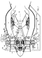
- ― la figure 1 montre une coupe longitudinale d'un propulseur combiné comportant une structure de tuyère réversible selon la définition de la présente invention;
- ― la figure 2 montre à titre d'exemple un circuit d'alimentation du type expander utilisable avec la structure du propulseur de la figure 1;
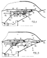
- ― la figure 3 montre en demi-coupe longitudinale le dispositif de tuyère représenté en mode turbo propulsion;
- ― la figure 4 est une demi-coupe similaire, vue en mode stato propulsion:
- ― la figure 5 est une vue similaire en mode de propulsion fusée.
- - Figure 1 shows a longitudinal section of a combined propellant comprising a reversible nozzle structure according to the definition of the present invention;
- - Figure 2 shows by way of example a supply circuit of the expander type usable with the structure of the propellant of Figure 1;
- - Figure 3 shows in longitudinal half-section the nozzle device shown in turbo propulsion mode;
- - Figure 4 is a similar half-section, viewed in propulsion mode:
- - Figure 5 is a similar view in rocket propulsion mode.
A la figure 1 a été représenté un propulseur combiné turbo-stato-fusée conforme aux objectifs de la présente invention et qui en inclut les perfectionnements. L'environnement externe du propulseur (circuits d'alimentation) a été représenté pour un cycle d'alimentation "expander" correspondant à la figure 2 à des fins d'exemplification. L'adaptation à un circuit "à générateur de gaz" ne modifie en rien la structure interne du propulseur, seules les alimentations étant modifiées.In Figure 1 has been shown a combined turbo-stato-rocket propellant according to the objectives of the present invention and which includes improvements. The external environment of the propellant (supply circuits) has been shown for an "expander" supply cycle corresponding to FIG. 2 for purposes of exemplification. Adaptation to a "gas generator" circuit does not modify the internal structure of the propellant, only the power supplies being modified.
Le propulseur comporte une veine annulaire 1 formée entre un corps central 2 et un carter externe 3. En amont de la veine est disposé un compresseur d'air 4 ici formé de deux étages contrarotatifs 4a, 4b reliés par des arbres concentriques 5a, 5b à deux rotors eux-mêmes contrarotatifs et imbriqués 6a, 6b, d'une turbine de puissance 6, disposée à l'intérieur du corps central en aval du compresseur 4.The propellant comprises an
Dans la partie aval du corps est disposé un moteur-fusée 9 dont les gaz propulsifs sont éjectés dans une tuyère 10 formée d'une première section divergente 10a, d'une seconde section 10b amovible et d'une troisième section divergente fixe 10c.In the downstream part of the body is arranged a rocket motor 9, the propellant gases of which are ejected into a
La veine annulaire 1 servant aux modes de propulsion turbo et stato débouche dans la tuyère 10 à l'emplacement qu'occupe en mode fusée la section amovible 10b. Un dispositif 11 d'excamotage de la section 10b du divergent du moteur-fusée 9, et de mise en place d'un moyen de variation de section du col de tuyère est disposé à l'intérieur du corps central 2. Il permet après escamotage de la section 10b de mettre en place dans la veine des volets 12 en forme de pétale dont la position axiale permettra de faire varier continûment la section du col de la tuyère convergente divergente dans les deux modes de fonctionnement turbo et stato.The
La turbine de puissance 6 est alimentée en gaz sous pression provenant d'un circuit d'alimentation externe (qui sera détaillé plus loin en regard de la figure 2), les gaz de turbine parvenant à la partie amont de la turbine au moyen d'une tubulure d'admission 7 traversant des bras structuraux 8 qui relient et maintiennent le corps central 2 au carter externe 3.The
En sortie de turbine, les gaz qui l'ont traversée sont admis dans la chambre de combustion de la veine 1 au moyen d'un dispositif d'injection 13 afin d'y être mélangés à l'air issu du compresseur 4 et brûlés en sortie du dispositif d'injection. Celui-ci est constitué de bras radiaux 14 régulièrement répartis dans la veine.At the outlet of the turbine, the gases which have passed through it are admitted into the combustion chamber of the
Si l'on regarde maintenant la figure 2, on a représenté un type d'alimentation en ergols compatible avec la structure de propulseur décrit à la figure 1.If we now look at Figure 2, we have shown a type of propellant supply compatible with the propellant structure described in Figure 1.
A la figure 2 on a schématisé un propulseur combiné turbo-stato-fusée à cycle dit expander.In Figure 2 there is shown schematically a combined turbo-stato-rocket propellant known as an expander.
Dans ce schéma, bien que l'on ait représenté la turbine de puissance et le moteur fusée en dehors de la veine d'air, pour des raisons de commodité, il s'agit bien respectivement de la turbine 6 et de la fusée centrale 9 disposées dans le corps central 2 du propulseur de la figure 1.In this diagram, although the power turbine and the rocket engine have been represented outside the air stream, for reasons of convenience, it is indeed
Dans un propulseur à cycle expander, le seul ergol utilisé en mode stato ou turbo est l'hydrogène.In an expander cycle propellant, the only propellant used in stato or turbo mode is hydrogen.
L'hydrogène liquide issu d'un réservoir de stockage 101 est pompé au moyen d'une turbopompe 102 puis est amené par une canalisation 103 et deux vannes 104,105 d'une part à un échangeur de chaleur 106 disposé sur la paroi de la chambre de combustion et d'autre part à une canalisation 107 qui, munie d'un clapet anti-retour 108 va alimenter les turbines de deux turbopompes, l'une 102 déjà citée et l'autre 109 destinée à l'alimentation en oxygène du moteur-fusée 9. Une vanne 110 permet d'isoler la turbopompe 109 du circuit quand besoin est, c'est à dire en modes turbo et stato.The liquid hydrogen coming from a
En sortie des turbines des turbopompes 102 et 109, l'hydrogène qui vient d'être détendu et qui a donc utilisé une partie de son énergie, est séparé en deux circuits dont l'un, 111, commandé par une vanne 112 autorise l'injection d'hydrogène dans la cavité 14f des bras radiaux et 19b, 20b des anneaux du dispositif d'injection 13, et dont l'autre 113 se ramifie lui même en deux parties 114 et 7 commandées chacune par une vanne 115, 116. Le circuit 7 alimente la turbine de puissance 6 tandis que le circuit 114 alimentera en mode fusée le moteur fusée 9. La sortie de la turbine 6 est reliée à la partie interne du dispositif d'injection 13 au travers de la virole 15. Si l'on revient à l'échangeur de chaleur 106, on voit que l'hydrogène en sortie dudit échangeur, où il a prélevé des calories et augmenté son enthalpie, est utilisé pour alimenter deux circuits, l'un 117 commandé par une vanne 118 permet l'injection en mode stato de l'hydrogène dans les cavités 14f des bras radiaux, et 19b, 20b des anneaux collecteurs du dispositif d'injection 13, tandis que l'autre circuit 119 va rejoindre la tubulure 107 en aval du clapet anti-retour 108 pour apporter l'énergie nécessaire à l'entraînement de la turbopompe 102 en modes turbo et stato. En mode fusée, les turbopompes 102 et 109 sont entraînées par l'hydrogène circulant dans la tubulure 107 qui a prélevé des calories dans un échangeur de chaleur 90 situé sur la paroi de la chambre fusée 9.At the outlet of the turbopumps of
Pour finir la description du circuit d'alimentation en ergols, il faut ajouter qu'il comporte un réservoir d'oxygène 120 qui peut être isolé par une vanne 121 et dont la sortie 122 est branchée sur la pompe de la turbopompe 109 dont le débit de sortie alimente, par une tubulure 123 en mode fusée seulement, le moteur-fusée 9.To finish the description of the propellant supply circuit, it should be added that it includes an
Les différents modes de fonctionnement sont conditionnés par l'ouverture/fermeture des différentes vannes ci-dessus mentionnées afin d'alimenter ou d'interrompre telle ou telle autre partie du circuit, ce qui peut être résumé par le tableau suivant dans lequel les différents modes de fonctionnement sont indiqués avec en regard, l'état d'ouverture (0) / fermeture (F) de chacune des vannes:

Le fonctionnement d'un tel propulseur est le suivant:The operation of such a thruster is as follows:
Le démarrage est assuré par un démarreur à poudre (non représenté) qui entraîne la turbine de turbopompe à LH₂ 102. En mode turboexpander, la vanne 110 étant fermée, la turbopompe à LOx 109 est arrêtée. La vanne 105 étant également fermée, la totalité du débit d'hydrogène passe dans l'échangeur de chaleur 106.Starting is ensured by a powder starter (not shown) which drives the LHop 102 turbopump turbine. In turboexpander mode, the
LH₂, comprimé par la turbopompe 102 et vaporisé dans l'échangeur 106 entraîne la turbopompe 102 puis la turbine 6 du moteur, (laquelle entraîne le compresseur 4) et enfin est injecté dans la chambre de combustion par l'intérieur des bras radiaux 14. Simultanément la vanne 118 étant ouverte, la partie radialement externe des bras 14 est alimentée en hydrogène directement depuis la sortie de l'échangeur de chaleur 106, ce qui permet d'assurer un bon refroidissement du bord de fuite des bras 14 et des anneaux collecteurs 19 et 20.LH₂, compressed by the
Le passage en mode statoréacteur s'effectue en isolant la turbine 6 par fermeture de la vanne 116 et ouverture simultanée de la vanne 112 de façon à ce que l'hydrogène en sortie de turbine de la turbopompe 102 soit injecté au moyen de la canalisation 111, des bras 14 et des anneaux collecteurs. Les vannes 104,118 étant ouvertes, la partie du débit d'hydrogène sorti de l'échangeur 106, qui n'est pas utilisé dans la turbopompe 102 est injectée directement au moyen de la canalisation 117 dans les bras 14 du dispositif d'injection 13. La totalité de l'injection d'hydrogène en mode stato est donc assurée depuis le bord externe de la veine par les bras d'injection 14.The transition to ramjet mode is carried out by isolating the
Le passage en mode fusée s'effectue par fermeture de la vanne 104 et ouverture simultanée des vannes 105, 110, 115 et 121. L'hydrogène issu de la pompe 102 alimente par 107 les turbines des deux turbopompes 102 et 109, puis par 113 et 114 est injecté dans la chambre du moteur fusée 9.The transition to rocket mode is carried out by closing the
L'oxygène pompé par 109 est amené par la canalisation 123 à la chambre du moteur-fusée 9.The oxygen pumped by 109 is brought via
Dans ce dernier mode de fonctionnement, la turbine 6 n'est pas alimentée et le compresseur 4 n'est plus alimenté en air, l'entrée d'air ayant été fermée. Les bras radiaux d'injection 14 ne sont alors plus alimentés du tout.In this latter operating mode, the
Pour assurer le réglage de la section du col de la tuyère annulaire en modes turbo et stato, et son obturation en mode moteur-fusée les moyens mobiles globalement référencés 11 sur la figure 1 vont être décrits plus en détail en regard des figures 3 à 5.To ensure the adjustment of the section of the neck of the annular nozzle in turbo and stato modes, and its closure in rocket engine mode, the mobile means generally referenced 11 in FIG. 1 will be described in more detail with reference to FIGS. 3 to 5 .
A l'intérieur de la partie aval cylindrique 2a du corps central 2 sont disposés des rails longitudinaux fixes 16 tenus sur la partie amont du moteur fusée 9 par un anneau 16c porté par une bride conique 16a et sur la première section 10a de tuyère divergente par une bride conique 16b.Inside the downstream
Entre la virole cylindrique 2a et les rails 16 sont disposés plusieurs ensembles 11, par exemple trois répartis à 120° autour du corps central ou comme le montre la figure 1, quatre répartis à 90°.Between the
Chaque ensemble 11 comporte un premier vérin à vis 17 disposé longitudinalement dont le corps 17a est fixé sur la partie amont du rail 16 et dont la tige 17b, orientée vers l'aval est solidaire d'une virole cylindrique mobile 18 apte à coulisser en translation axiale sous la virole 2a contre laquelle elle est disposée.Each
Sur le bord aval de la virole coulissante 18 sont articulés (au moyen de pattes 19 coopérant avec des chapes 20 par des axes 21) des volets mobiles 12 en forme de pétales possédant une double courbure d'abord tournée vers l'axe du propulseur dans la partie amont des volets puis tournée radialement vers l'extérieur du propulseur dans la partie aval des volets.On the downstream edge of the sliding
L'ensemble formé par la virole cylindrique 18 et les volets 12, mobile en translation axiale au moyen du vérin 17, constitue, avec la partie aval convergente 3a du carter externe 3 qui se raccorde sur la section 10c divergente de la tuyère, les moyens de formation du col convergent-divergent et de variation de la section de ce dit col.The assembly formed by the
Un second vérin à vis 22, dont le corps 22a est solidaire d'une pièce de liaison 23 entre la tige 17b du premier vérin 17 et la virole 18, est disposé parallèlement à l'axe longitudinal du propulseur avec sa tige 22b orientée vers l'aval. Sur la tête du second vérin 22 est articulée une structure intermédiaire 24 mobile en translation axiale et possédant des galets 25 de roulement sur le rail fixe 16. Sur la partie aval de la structure mobile 24 est soudée une virole conique formant la seconde section divergente 10b de la tuyère 10, et c'est sur une chape 26 de cette virole 10b qu'est articulée la tige 22b du second vérin 22.A
Sur sa partie radialement externe, la structure mobile 24 comporte deux rails de guidage 27 longitudinaux, avec lesquels coopèrent des galets de roulement 28 portés par une biellette 29 articulée sur l'axe de liaison 21 entre la virole 18 et les volets 12, pour permettre le coulissement des galets 28 dans les rails 27. De cette façon lors de l'extension de la tige du second vérin 22, qui amène vers l'aval la section divergente 10b de la tuyère, alors que le premier vérin 17 est en position tige rentrée, les volets s'escamotent vers l'extérieur pour laisser libre passage à la virole conique 10b (figure 5). Cette disposition permet de reconstituer la tuyère divergente 10 lors du passage du propulseur en mode fusée, l'éjection de gaz dans la veine annulaire ayant cessé à cet instant.On its radially external part, the
Les séquences de fonctionnement sont alors les suivantes:The operating sequences are then as follows:
En mode de fonctionnement turboréacteur au sol (figure 3), le premier et le second vérin 17 et 22 sont en position rétractée et la seconde section de tuyère divergente 10b est escamotée, les volets 12 étant en position amont dans laquelle ils définissent une section S1 de col de tuyère annulaire maximale pour l'éjection des gaz du turboréacteur.In ground turbojet operating mode (Figure 3), the first and
Le vérin 17 est ensuite déployé progressivement lors de l'accélération en mode turbo puis en mode stato. A la fin du mode statoréacteur (figure 4), le premier vérin 17 est en position complètement étendue et le second 22 rétracté, la première virole cylindrique mobile 18 étant en position aval et les volets 12 en position aval dans laquelle ils définissent une section S2 de col de tuyère minimale pour l'éjection des gaz du statoréacteur.The
En mode fusée, (figure 5) le premier vérin 17 est en position rétractée et le second vérin 22 étendu, les volets 12 étant escamotés tandis que la seconde section 10b de tuyère divergente est en position aval où elle obture la veine annulaire et assure la continuité de la tuyère 10 entre les première et troisième sections fixes 10a et 10C pour permettre l'éjection des gaz du moteur-fusée 9.In rocket mode, (Figure 5) the
On voit sur les figures 3 et 4 qu'en jouant sur la position du vérin 17, on peut faire passer la section de col S de la tuyère annulaire de sa valeur maximale S₁ à sa valeur minimale S₂ de façon continue et réversible lors de l'accélération (passage du mode de propulsion turbo au mode stato et réciproquement).It can be seen in FIGS. 3 and 4 that by playing on the position of the
On voit également que l'escamotage des volets et donc l'obturation de la veine et la formation de la tuyère fusée sont réversibles ce qui permet de passer indifféremment du mode stato au mode fusée et réciproquement.It can also be seen that the retraction of the flaps and therefore the obturation of the vein and the formation of the rocket nozzle are reversible, which makes it possible to switch from stato mode to rocket mode and vice versa.
Bien que l'invention ait été explicitée appliquée à un propulseur à cycle expander, elle peut tout autant être appliquée à un propulseur dont la turbine est entraînée par un générateur de gaz externe et/ou possède un réchauffeur de gaz.Although the invention has been explained when applied to an expander cycle propellant, it can just as easily be applied to a propellant whose turbine is driven by an external gas generator and / or has a gas heater.
L'invention peut également être appliquée sans limitation à un propulseur dont l'architecture du compresseur et de la turbine serait différente de celle ici représentée.The invention can also be applied without limitation to a propellant whose architecture of the compressor and of the turbine would be different from that shown here.
L'invention s'applique donc indifféremment à tout type de propulseurs utilisant successivement les trois modes de propulseur turbo, stato et fusée et dont la veine d'éjection en modes turbo et stato est annulaire et entoure le moteur-fusée.The invention therefore applies equally to any type of propellant successively using the three modes turbo, stato and rocket propellant and whose ejection stream in turbo and stato modes is annular and surrounds the rocket engine.
Claims (11)
Applications Claiming Priority (2)
| Application Number | Priority Date | Filing Date | Title |
|---|---|---|---|
| FR8812646 | 1988-09-28 | ||
| FR8812646A FR2637017B1 (en) | 1988-09-28 | 1988-09-28 | NOZZLE STRUCTURE FOR TURBO-STATO-FUSEE COMBINED PROPELLER |
Publications (2)
| Publication Number | Publication Date |
|---|---|
| EP0362052A1 EP0362052A1 (en) | 1990-04-04 |
| EP0362052B1 true EP0362052B1 (en) | 1991-10-30 |
Family
ID=9370467
Family Applications (1)
| Application Number | Title | Priority Date | Filing Date |
|---|---|---|---|
| EP19890402637 Expired - Lifetime EP0362052B1 (en) | 1988-09-28 | 1989-09-27 | Nozzle structure for a combined turbo-static rocket |
Country Status (4)
| Country | Link |
|---|---|
| EP (1) | EP0362052B1 (en) |
| JP (1) | JPH0672573B2 (en) |
| DE (1) | DE68900386D1 (en) |
| FR (1) | FR2637017B1 (en) |
Cited By (7)
| Publication number | Priority date | Publication date | Assignee | Title |
|---|---|---|---|---|
| WO2001094197A1 (en) * | 2000-06-07 | 2001-12-13 | Pursuit Dynamics Plc | Propulsion system |
| US6662549B2 (en) | 2000-06-07 | 2003-12-16 | Pursuit Dynamics Plc | Propulsion system |
| US8193395B2 (en) | 2007-05-02 | 2012-06-05 | Pursuit Dynamics Plc | Biomass treatment process and system |
| US8419378B2 (en) | 2004-07-29 | 2013-04-16 | Pursuit Dynamics Plc | Jet pump |
| US8789769B2 (en) | 2006-09-15 | 2014-07-29 | Tyco Fire & Security Gmbh | Mist generating apparatus and method |
| US9004375B2 (en) | 2004-02-26 | 2015-04-14 | Tyco Fire & Security Gmbh | Method and apparatus for generating a mist |
| US9010663B2 (en) | 2004-02-26 | 2015-04-21 | Tyco Fire & Security Gmbh | Method and apparatus for generating a mist |
Families Citing this family (6)
| Publication number | Priority date | Publication date | Assignee | Title |
|---|---|---|---|---|
| JP2707822B2 (en) * | 1990-10-05 | 1998-02-04 | 日産自動車株式会社 | Ram rocket |
| US20080103217A1 (en) | 2006-10-31 | 2008-05-01 | Hari Babu Sunkara | Polyether ester elastomer composition |
| CN102826227B (en) * | 2012-08-22 | 2015-09-09 | 冯加伟 | Unmanned space warfare machine |
| FR3001260B1 (en) * | 2013-01-18 | 2017-04-21 | Astrium Sas | DEVICE FOR STARTING A FIRED MOTOR TURBOPOMP |
| CN103993982A (en) * | 2014-04-25 | 2014-08-20 | 西北工业大学 | Double-S-bend infrared stealth spray pipe structure capable of achieving multi-direction thrust vector control |
| EP3985241B1 (en) * | 2020-10-14 | 2023-11-29 | Taiwan Innovative Space, Inc. | Motor and fuel-powered hybrid system for a rocket thruster |
Family Cites Families (7)
| Publication number | Priority date | Publication date | Assignee | Title |
|---|---|---|---|---|
| US2933886A (en) * | 1953-04-15 | 1960-04-26 | Sharma Devendra Nath | Turbojet engine convertible to ramjet engine |
| NL262125A (en) * | 1960-04-01 | |||
| US3192712A (en) * | 1962-12-31 | 1965-07-06 | Gen Electric | Load balancing arrangement for annular variable area jet exhaust nozzle |
| US3374631A (en) * | 1965-08-16 | 1968-03-26 | Mcdonnell Aircraft Corp | Combination subsonic and supersonic propulsion system and apparatus |
| US4213566A (en) * | 1978-08-25 | 1980-07-22 | Hercules Incorporated | Nested cone extendible nozzle system for a rocket motor |
| DE3427169A1 (en) * | 1984-07-24 | 1986-01-30 | Messerschmitt-Bölkow-Blohm GmbH, 8012 Ottobrunn | Rocket drive for space flights |
| DE3738703A1 (en) * | 1987-05-27 | 1988-12-08 | Mtu Muenchen Gmbh | COMBINED, SWITCHABLE JET ENGINE FOR DRIVING PLANES AND SPACES |
-
1988
- 1988-09-28 FR FR8812646A patent/FR2637017B1/en not_active Expired - Lifetime
-
1989
- 1989-09-26 JP JP25036789A patent/JPH0672573B2/en not_active Expired - Fee Related
- 1989-09-27 DE DE8989402637T patent/DE68900386D1/en not_active Expired - Lifetime
- 1989-09-27 EP EP19890402637 patent/EP0362052B1/en not_active Expired - Lifetime
Cited By (10)
| Publication number | Priority date | Publication date | Assignee | Title |
|---|---|---|---|---|
| WO2001094197A1 (en) * | 2000-06-07 | 2001-12-13 | Pursuit Dynamics Plc | Propulsion system |
| US6662549B2 (en) | 2000-06-07 | 2003-12-16 | Pursuit Dynamics Plc | Propulsion system |
| US9004375B2 (en) | 2004-02-26 | 2015-04-14 | Tyco Fire & Security Gmbh | Method and apparatus for generating a mist |
| US9010663B2 (en) | 2004-02-26 | 2015-04-21 | Tyco Fire & Security Gmbh | Method and apparatus for generating a mist |
| US8419378B2 (en) | 2004-07-29 | 2013-04-16 | Pursuit Dynamics Plc | Jet pump |
| US9239063B2 (en) | 2004-07-29 | 2016-01-19 | Pursuit Marine Drive Limited | Jet pump |
| US8789769B2 (en) | 2006-09-15 | 2014-07-29 | Tyco Fire & Security Gmbh | Mist generating apparatus and method |
| US9931648B2 (en) | 2006-09-15 | 2018-04-03 | Tyco Fire & Security Gmbh | Mist generating apparatus and method |
| US8193395B2 (en) | 2007-05-02 | 2012-06-05 | Pursuit Dynamics Plc | Biomass treatment process and system |
| US8513004B2 (en) | 2007-05-02 | 2013-08-20 | Pursuit Dynamics Plc | Biomass treatment process |
Also Published As
| Publication number | Publication date |
|---|---|
| FR2637017B1 (en) | 1990-11-30 |
| DE68900386D1 (en) | 1991-12-05 |
| JPH02125953A (en) | 1990-05-14 |
| FR2637017A1 (en) | 1990-03-30 |
| JPH0672573B2 (en) | 1994-09-14 |
| EP0362052A1 (en) | 1990-04-04 |
Similar Documents
| Publication | Publication Date | Title |
|---|---|---|
| EP2643579B1 (en) | Combined turbojet and ramjet engine | |
| EP0333585B1 (en) | Combined propulsion unit provided with an air breathing turbo jet | |
| EP0362052B1 (en) | Nozzle structure for a combined turbo-static rocket | |
| US5052176A (en) | Combination turbojet-ramjet-rocket propulsion system | |
| US6668542B2 (en) | Pulse detonation bypass engine propulsion pod | |
| EP0434565B1 (en) | Versatile combined propulsion engine for aeroplane or space shuttle | |
| EP0403372B1 (en) | Combined turbo-stato-rocket jet engine | |
| FR2599428A1 (en) | COMBINED PROPULSION DEVICE FOR AIRCRAFT, IN PARTICULAR FOR SPACE AIRCRAFT. | |
| FR2987081A1 (en) | Propulsion assembly for aerospace machine, has rocket engines forming ejectors to accelerate air flow in channel at supersonic speed, and conduit provided in interior wall downstream from output opening of channel | |
| US2972860A (en) | Combined variable ejector and thrust reverser | |
| EP0362053B1 (en) | Combined propulsion system having a structure compatible with two types of operation | |
| FR2561313A1 (en) | THRUST MODULATION DEVICE | |
| FR2687433A1 (en) | Propulsion unit with reversed components, with modulated supply | |
| EP0362054B1 (en) | Gas injection device for a combined turbo-stato-rocket thruster | |
| WO2021044096A1 (en) | Thrust reverser comprising a single actuator for controlling a mobile cowling | |
| EP4004358A1 (en) | Convergent-divergent flap pair for a variable-geometry turbojet engine nozzle, the flaps of which each comprise a cooling air circulation duct | |
| FR2698409A1 (en) | Turbojet ejection nozzle. | |
| FR2653496A1 (en) | INTEGRATED TURBO-STATOREACTOR, EQUIPPING AIRCRAFT FOR SUB AND / OR HYPERSONIC FLIGHT. | |
| US5105615A (en) | Turbojet engine with at least one axially movable arranged sliding valve | |
| US4529130A (en) | Turbo machine nozzle with thrust reverser | |
| EP4004359B1 (en) | Convergent-divergent flap pair for a variable-geometry turbojet engine nozzle comprising cooling air circulation ducts connected through contact surfaces | |
| WO2022096838A1 (en) | Turbine engine rear part comprising a nozzle of which flaps comprise levers connected by link rods to a synchronizing ring | |
| EP4240959A1 (en) | Jet engine rear part comprising a nozzle having flaps comprising levers that are movable by means of upstream and downstream bearing walls | |
| FR3100283A1 (en) | COUPLE CONVERGENT-DIVERGENT FLAP FOR VARIABLE GEOMETRY TURBOREACTOR NOZZLE WHOSE DIVERGENT FLAP INCLUDES A COOLING AIR EJECTION DUCT | |
| BE551416A (en) |
Legal Events
| Date | Code | Title | Description |
|---|---|---|---|
| PUAI | Public reference made under article 153(3) epc to a published international application that has entered the european phase |
Free format text: ORIGINAL CODE: 0009012 |
|
| 17P | Request for examination filed |
Effective date: 19891011 |
|
| AK | Designated contracting states |
Kind code of ref document: A1 Designated state(s): DE FR GB IT |
|
| 17Q | First examination report despatched |
Effective date: 19910408 |
|
| GRAA | (expected) grant |
Free format text: ORIGINAL CODE: 0009210 |
|
| AK | Designated contracting states |
Kind code of ref document: B1 Designated state(s): DE FR GB IT |
|
| ITF | It: translation for a ep patent filed |
Owner name: BARZANO' E ZANARDO MILANO S.P.A. |
|
| REF | Corresponds to: |
Ref document number: 68900386 Country of ref document: DE Date of ref document: 19911205 |
|
| GBT | Gb: translation of ep patent filed (gb section 77(6)(a)/1977) | ||
| PLBE | No opposition filed within time limit |
Free format text: ORIGINAL CODE: 0009261 |
|
| STAA | Information on the status of an ep patent application or granted ep patent |
Free format text: STATUS: NO OPPOSITION FILED WITHIN TIME LIMIT |
|
| 26N | No opposition filed | ||
| REG | Reference to a national code |
Ref country code: GB Ref legal event code: IF02 |
|
| REG | Reference to a national code |
Ref country code: FR Ref legal event code: CD Ref country code: FR Ref legal event code: TP |
|
| REG | Reference to a national code |
Ref country code: FR Ref legal event code: CD |
|
| PGFP | Annual fee paid to national office [announced via postgrant information from national office to epo] |
Ref country code: DE Payment date: 20070829 Year of fee payment: 19 |
|
| PGFP | Annual fee paid to national office [announced via postgrant information from national office to epo] |
Ref country code: GB Payment date: 20070830 Year of fee payment: 19 |
|
| PGFP | Annual fee paid to national office [announced via postgrant information from national office to epo] |
Ref country code: IT Payment date: 20070918 Year of fee payment: 19 |
|
| PGFP | Annual fee paid to national office [announced via postgrant information from national office to epo] |
Ref country code: FR Payment date: 20070820 Year of fee payment: 19 |
|
| GBPC | Gb: european patent ceased through non-payment of renewal fee |
Effective date: 20080927 |
|
| REG | Reference to a national code |
Ref country code: FR Ref legal event code: ST Effective date: 20090529 |
|
| PG25 | Lapsed in a contracting state [announced via postgrant information from national office to epo] |
Ref country code: DE Free format text: LAPSE BECAUSE OF NON-PAYMENT OF DUE FEES Effective date: 20090401 Ref country code: IT Free format text: LAPSE BECAUSE OF NON-PAYMENT OF DUE FEES Effective date: 20080927 |
|
| PG25 | Lapsed in a contracting state [announced via postgrant information from national office to epo] |
Ref country code: FR Free format text: LAPSE BECAUSE OF NON-PAYMENT OF DUE FEES Effective date: 20080930 |
|
| PG25 | Lapsed in a contracting state [announced via postgrant information from national office to epo] |
Ref country code: GB Free format text: LAPSE BECAUSE OF NON-PAYMENT OF DUE FEES Effective date: 20080927 |