EP0361999B1 - Probe for optical sensor - Google Patents
Probe for optical sensor Download PDFInfo
- Publication number
- EP0361999B1 EP0361999B1 EP89402331A EP89402331A EP0361999B1 EP 0361999 B1 EP0361999 B1 EP 0361999B1 EP 89402331 A EP89402331 A EP 89402331A EP 89402331 A EP89402331 A EP 89402331A EP 0361999 B1 EP0361999 B1 EP 0361999B1
- Authority
- EP
- European Patent Office
- Prior art keywords
- blood
- light
- optical
- optical sensor
- optical fiber
- Prior art date
- Legal status (The legal status is an assumption and is not a legal conclusion. Google has not performed a legal analysis and makes no representation as to the accuracy of the status listed.)
- Expired - Lifetime
Links
- 239000000523 sample Substances 0.000 title claims description 35
- 230000003287 optical effect Effects 0.000 title claims description 26
- 210000004369 blood Anatomy 0.000 claims description 42
- 239000008280 blood Substances 0.000 claims description 42
- 239000013307 optical fiber Substances 0.000 claims description 37
- 239000000835 fiber Substances 0.000 claims description 7
- 230000017531 blood circulation Effects 0.000 claims description 5
- 238000005534 hematocrit Methods 0.000 claims description 5
- 238000009792 diffusion process Methods 0.000 claims description 2
- 230000008878 coupling Effects 0.000 claims 3
- 238000010168 coupling process Methods 0.000 claims 3
- 238000005859 coupling reaction Methods 0.000 claims 3
- 102000001554 Hemoglobins Human genes 0.000 description 12
- 108010054147 Hemoglobins Proteins 0.000 description 12
- 229910052760 oxygen Inorganic materials 0.000 description 12
- 239000001301 oxygen Substances 0.000 description 12
- QVGXLLKOCUKJST-UHFFFAOYSA-N atomic oxygen Chemical compound [O] QVGXLLKOCUKJST-UHFFFAOYSA-N 0.000 description 11
- 210000003743 erythrocyte Anatomy 0.000 description 11
- 238000010586 diagram Methods 0.000 description 7
- 238000005259 measurement Methods 0.000 description 7
- CURLTUGMZLYLDI-UHFFFAOYSA-N Carbon dioxide Chemical compound O=C=O CURLTUGMZLYLDI-UHFFFAOYSA-N 0.000 description 6
- 230000004087 circulation Effects 0.000 description 5
- 229920003229 poly(methyl methacrylate) Polymers 0.000 description 4
- 239000004926 polymethyl methacrylate Substances 0.000 description 4
- 229910002092 carbon dioxide Inorganic materials 0.000 description 3
- 239000001569 carbon dioxide Substances 0.000 description 3
- 238000010276 construction Methods 0.000 description 3
- 230000000694 effects Effects 0.000 description 3
- 238000000034 method Methods 0.000 description 3
- 101100243025 Arabidopsis thaliana PCO2 gene Proteins 0.000 description 2
- 210000000601 blood cell Anatomy 0.000 description 2
- 230000005611 electricity Effects 0.000 description 2
- 238000002474 experimental method Methods 0.000 description 2
- 239000004800 polyvinyl chloride Substances 0.000 description 2
- 229920000915 polyvinyl chloride Polymers 0.000 description 2
- 238000005070 sampling Methods 0.000 description 2
- 238000012546 transfer Methods 0.000 description 2
- 210000001367 artery Anatomy 0.000 description 1
- 230000005540 biological transmission Effects 0.000 description 1
- 210000004204 blood vessel Anatomy 0.000 description 1
- 230000008859 change Effects 0.000 description 1
- 238000010292 electrical insulation Methods 0.000 description 1
- 238000007654 immersion Methods 0.000 description 1
- 230000006872 improvement Effects 0.000 description 1
- 230000001678 irradiating effect Effects 0.000 description 1
- 210000004072 lung Anatomy 0.000 description 1
- 238000012544 monitoring process Methods 0.000 description 1
- 230000003204 osmotic effect Effects 0.000 description 1
- 150000002926 oxygen Chemical class 0.000 description 1
- 230000036284 oxygen consumption Effects 0.000 description 1
- 229920003023 plastic Polymers 0.000 description 1
- 239000004033 plastic Substances 0.000 description 1
- 230000008569 process Effects 0.000 description 1
- 239000010453 quartz Substances 0.000 description 1
- 230000035945 sensitivity Effects 0.000 description 1
- VYPSYNLAJGMNEJ-UHFFFAOYSA-N silicon dioxide Inorganic materials O=[Si]=O VYPSYNLAJGMNEJ-UHFFFAOYSA-N 0.000 description 1
- 238000001356 surgical procedure Methods 0.000 description 1
- 210000003462 vein Anatomy 0.000 description 1
Images


Classifications
-
- A—HUMAN NECESSITIES
- A61—MEDICAL OR VETERINARY SCIENCE; HYGIENE
- A61B—DIAGNOSIS; SURGERY; IDENTIFICATION
- A61B5/00—Measuring for diagnostic purposes; Identification of persons
- A61B5/145—Measuring characteristics of blood in vivo, e.g. gas concentration or pH-value ; Measuring characteristics of body fluids or tissues, e.g. interstitial fluid or cerebral tissue
- A61B5/1455—Measuring characteristics of blood in vivo, e.g. gas concentration or pH-value ; Measuring characteristics of body fluids or tissues, e.g. interstitial fluid or cerebral tissue using optical sensors, e.g. spectral photometrical oximeters
- A61B5/14551—Measuring characteristics of blood in vivo, e.g. gas concentration or pH-value ; Measuring characteristics of body fluids or tissues, e.g. interstitial fluid or cerebral tissue using optical sensors, e.g. spectral photometrical oximeters for measuring blood gases
- A61B5/14557—Measuring characteristics of blood in vivo, e.g. gas concentration or pH-value ; Measuring characteristics of body fluids or tissues, e.g. interstitial fluid or cerebral tissue using optical sensors, e.g. spectral photometrical oximeters for measuring blood gases specially adapted to extracorporeal circuits
Definitions
- This invention relates to a probe for an optical sensor used to measure the degree of oxygen saturation in hemoglobin and the hemoglobin concentration in blood or an organism. More particularly, the present invention relates to an optical sensor probe used by being inserted in an extracorporeal circulation circuit such as a pump-oxygenator circuit to continuously monitor the degree of oxygen saturation in hemoglobin and the hemoglobin concentration.
- extracorporeal circulation is temporarily effected by using a pump-oxygenator instead of the heart and the lung of the organism.
- the degree of oxygen saturation in blood in arteries and veins and the hemoglobin concentration thereof are measured by periodically sampling the blood.
- the oxygen saturation cannot be continuously examined.
- a method for preventing such a risk is well known in which the blood of the subject is irradiated with light having a particular wavelength and the degree of oxygen saturation is obtained from the intensity of the reflected light or transmission light. Measurement of hemoglobin concentration has also been studied but no method for measuring this factor with accuracy has been established.
- Conventional detectors for detecting the intensity of light reflected in blood are designed to be immersed in blood to detect the intensity of reflected light and therefore entail the following problems.
- characteristics of circuit component parts are changed under the influence of the temperature of the blood and so on, and the value of the intensity of reflected light detected is thereby changed, resulting in difficulty in measuring the hemoglobin concentration and other quantities with accuracy.
- the intensity of reflected light cannot be measured with stability and accuracy due to the influence of the size and shape of blood cells although the intensity of reflected light is correlative to the hemoglobin concentration.
- an object of the present invention is to provide an optical sensor probe which makes it possible to continuously measure the intensity of light reflected in blood with safety and with accuracy.
- Another object of the present invention is to provide an optical sensor probe designed to completely insulate light transmitting members electrically from an electric circuit section by using optical fibers as the light transmitting members in order to eliminate the risk of leakage of electricity.
- Still another object of the present invention is to provide an optical sensor free from any influence of the temperature of blood on temperature characteristics of electronic parts including an operational amplifier.
- a further object of the present invention is to provide an optical sensor probe designed to obtain the intensity of reflected light substantially irrespective of properties of blood cells including the size of red blood cells by increasing the distance between a light emitting portion and a light receiving portion constituted by end surfaces of optical fibers while maintaining suitable performance of detecting the intensity of reflected light.
- a still further object of the present invention is to provide an optical sensor probe which makes it possible to continuously measure the intensity of reflected light while maintaining electrical insulation for safety and to improve the accuracy with which the degree of oxygen saturation and the hemoglobin concentration are calculated on the basis of measured light intensities.
- the present invention proposes an optical sensor probe as defined in claim 1.
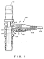
- Fig. 1 shows in section the configuration of an optical sensor probe which represents an embodiment of the present invention with a portion thereof cut away for illustration
- Fig. 2 is a schematic diagram of propagation of light emitted from a light emitting portion, reflected by red blood cells and introduced into a light receiving portion.
- an optical sensor probe 100 is fixed by a connector 102 to a conduit 101 which constitutes an extracorporeal circulation circuit and which is filled with blood flowing therethrough.
- An end surface 103 of the probe 100 is worked so as to be flat and flush with an inner wall surface 104 of the connector 102 in order to prevent the flow of blood from being disturbed.
- the optical sensor probe 100 is basically formed of four parts: a probe body 110 in which two optical PMMA (polymethylmethacrylate) fibers 105 and 106 are accommodated and fixed; a fixing nut 107 for fixing the probe body 110 to the connector 102; a soft polyvinyl chloride cap 109 for preventing a polyvinyl chloride tube 108 for protection of the optical fibers 105 and 106 from being bent with an extremely large curvature at the position of connection to the optical sensor probe 100; and an O-ring 111 for preventing any leakage of blood. Quartz fibers may be used instead of the PMMA fibers.
- the two optical fibers 105 and 106 are fixed in the probe 100 of this embodiment.
- One (105) of these optical fibers constitutes a light emitting portion through which light transmitted from a light source such as an LED is introduced into the conduit 101 to irradiate blood, and the other optical fiber 106 is used to transmit part of light introduced into the blood through the optical fiber 105 and reflected by red blood cells in the blood to a light detecting element such as a photodiode capable of detecting the intensity of light.
- light having a particular wavelength is emitted into blood 202 from the light emitting portion constituted by the end surface of the optical fiber 105 in contact with the blood in the conduit 101.
- Part of light reflected by red blood cells 201 is introduced into the light receiving portion constituted by the optical fiber 106.
- the introduced part of the reflected light is transmitted to the unillustrated light detecting element through the optical fiber 106, thereby measuring the intensity of the light reflected in the blood.
- the intensity of this reflected light is changed if the distance 210 between the optical fibers 105 and 106 is changed. This effect is thought to be based on dependence of the intensity of the reflected light upon the path through which light emitted from the optical fiber 105 travels in the blood 202 and reaches the light receiving portion while repeating scattering, as explained below briefly. If the distance 210 (between the centers of the optical fibers 105 and 106) is small, the proportion of scattered light from the vicinity of the end contact surfaces of the fibers 105 and 106 in the detected reflected light is large. As the distance 210 is increased, the proportion of scattered light from red blood cells 201 remote from the end contact surfaces increases.
- the distance 210 between the light emitting optical fiber 105 and the light receiving optical fiber 106 is increased, the influence of disturbance of the blood flow in the vicinity of the connector inner wall 104 and the influence of hematocrit variation upon the intensity of the reflected light are small.
- An increase in the distance 210 also results in an improvement in the diffusion of light. It is thereby possible to receive uniform reflected light by limiting the influence of the size of the red blood cells and other factors.
- Fig. 3 shows changes in the hematocrit value with respect to the blood PH changed by controlling the partial pressure of carbon dioxide PCO2 and the NaHCO3 ⁇ concentration in the blood in mmHg and mM unit, respectively.
- Fig. 4 shows the intensity of reflected light having a wavelength of 800 nm with respect to PH values in a case where the distance between the irradiating and light receiving optical fibers was 0.25 mm or as well as in a case where the distance between these fibers was 1.95 mm.
- the hematocrit value changed in proportion to the blood PH value with respect to each value of the carbon dioxide PCO2 and the NaHCO3 ⁇ concentration. This effect is thought to be mainly based on expansion or shrinkage of red blood cells due to changes in the osmotic pressure.
- each of the two optical fibers 105 and 106 was an optical PMMA plastic fiber having a diameter of 0.25 mm when the distance D was 0.25 mm or a diameter of 0.75 mm when the distance D was 1.95 mm.
- red blood cells varies in different organisms
- the light intensity of reflected by red blood cells can be measured without depending upon the size of the red blood cells if the distance D is set to a suitable value.
- the light emitting portion for introducing light into blood and the light receiving portion for receiving light reflected in blood are constituted by end portions of the optical fibers.
- the present invention is not limited to this arrangement and can of course be arranged in such a manner that a light emitting device such as a light emitting diode (LED) constitutes the light emitting portion to be brought into contact with blood while a light receiving device such as a photosensor constitutes the light receiving portion to be brought into contact with blood.
- a light emitting device such as a light emitting diode (LED) constitutes the light emitting portion to be brought into contact with blood
- a light receiving device such as a photosensor constitutes the light receiving portion to be brought into contact with blood.
- the portions including the LED and the photosensor to be brought into contact with blood are electrically insulated.
- Fig. 5 shows a schematic block diagram of the construction of an apparatus for measuring the oxygen saturation by using the optical sensor probe 100 of the above-described embodiment.
- the probe 100 is used by being inserted in an extracorporeal circulation circuit such as a pump-oxygenator circuit to measure the intensity of light reflected in blood.
- a pulse oscillator 12 outputs drive timing signals for driving an LED assembly 14 (LEDs 141 and 142) to a LED driving circuit 13, and also outputs timing signals for sampling the reflected light intensity with respect to different wavelengths to a sample and hold circuit 18.
- the LED driving circuit 13 drives one of the LEDs 141 and 142 of the LED assembly 14 to effect emission of light.
- the LED assembly 14 is capable of outputting light having a wavelength of 660 nm or light having a wavelength of 800 nm.
- two light emitting diodes LED 141 (wavelength: 660 nm) and LED 142 (wavelength: 800 nm) constitute the LED assembly 14.
- Lights having different wavelengths emitted from respective LEDs are introduced into one optical fiber through an optical coupler and is supplied to the optical fiber 105 of the probe 100.
- the LED assembly may be replaced by one LED if the wavelength of light output from this LED can be changed between 660 nm and 800 nm by, for example, changing the driving voltage.
- a connector 15 is provided for connection between the probe 100 and the body of the apparatus.
- the probe 100 and the apparatus body are connected by the cable 108 in which the optical fibers 105 and 106 are accommcdated.
- a photoelectric transfer device and a preamplifier are integrally disposed.
- the section 16 is supplied with reflected lights transmitted through the optical fiber 106 of the probe 100 and outputs an electric signal representing the intensities of the supplied lights.
- a main amplifier 17 further amplifies the electric signal supplied from the photoelectric transfer section 16.
- the sample and hold circuit 18 is supplied with the timing signals from the pulse oscillator 12 and samples and holds the analog signal supplied from the main amplifier section 17 in synchronization with the timing signals.
- Lights of the respective wavelengths emitted form the LED assembly 14 are controlled by using the timing signals supplied from the pulse oscillator 12 so as to avoid any overlap of these lights with respect to time.
- the intensities of reflected lights of the respective wavelengths are held by the sample and hold circuit 18 independently of each other. Noise components of a signal supplied from the sample and hold circuit 18 are filtered off by a filter circuit 19 and the signal is thereafter supplied to a control section 20.
- the analog signal supplied from the filter circuit 19 is converted into a digital signal by an A/D converter 22 and is supplied to a CPU circuit 21.
- the CPU circuit 21 that includes a microprocessor and so on performs control operations in accordance with control programs and various items of data stored in a ROM 24.
- a RAM 25 is used as a working area for the CPU circuit, and various items of data are temporarily stored in the RAM 25.
- An operational panel 23 through which the apparatus is operated by the operator, and a command to start measurement and various kinds of instructions can be input by using the operational panel 23.
- a display 27 is driven by a display circuit 16 to display messages to the operator, results of measurement and so on.
- An external output terminal 29 is provided to output information including measurement data to an external unit such as a printer connected to the apparatus.
- a plurality of values representing the intensities of lights of the wavelengths of 660 nm and 800 nm reflected in blood are obtained and the averages of these values are calculated. This step is necessary for reducing the influence of errors in information on the respective reflected light intensities.
- the average values of the reflected light intensities are normalized by the following calculation.
- the intensity of light reflected by a white board having a constant reflectance is calculated with respect to each wavelength, and the intensities thereby obtained are set as W660 and W800.
- SO2 a3(N1/N2)3 + a2(N1/N2)2 + a1(N1/N2) + a0
- a0, a1 , a2 and a3 are constants which depend upon the characteristics of the optical sensor probe 100 and the animal species. For example, twenty values (measured in five seconds) are averaged with respect to each wavelength, the averaged values are calibrated, and the degree of oxygen saturation is calculated from these values.
Landscapes
- Health & Medical Sciences (AREA)
- Physics & Mathematics (AREA)
- Life Sciences & Earth Sciences (AREA)
- Biomedical Technology (AREA)
- Medical Informatics (AREA)
- Biophysics (AREA)
- Pathology (AREA)
- Engineering & Computer Science (AREA)
- Spectroscopy & Molecular Physics (AREA)
- Heart & Thoracic Surgery (AREA)
- Optics & Photonics (AREA)
- Molecular Biology (AREA)
- Surgery (AREA)
- Animal Behavior & Ethology (AREA)
- General Health & Medical Sciences (AREA)
- Public Health (AREA)
- Veterinary Medicine (AREA)
- Measurement Of The Respiration, Hearing Ability, Form, And Blood Characteristics Of Living Organisms (AREA)
- Investigating Or Analysing Materials By Optical Means (AREA)
Description
- This invention relates to a probe for an optical sensor used to measure the degree of oxygen saturation in hemoglobin and the hemoglobin concentration in blood or an organism. More particularly, the present invention relates to an optical sensor probe used by being inserted in an extracorporeal circulation circuit such as a pump-oxygenator circuit to continuously monitor the degree of oxygen saturation in hemoglobin and the hemoglobin concentration.
- For open heart surgery or the like, extracorporeal circulation is temporarily effected by using a pump-oxygenator instead of the heart and the lung of the organism. To know the oxygen transport rate of blood circulation and the oxygen consumption in the organism during the extracorporeal circulation, the degree of oxygen saturation in blood in arteries and veins and the hemoglobin concentration thereof are measured by periodically sampling the blood. In this system, the oxygen saturation cannot be continuously examined. There is therefore a risk of a delay in the desired treatment for an abrupt change in the physical state of the subject or patient. A method for preventing such a risk is well known in which the blood of the subject is irradiated with light having a particular wavelength and the degree of oxygen saturation is obtained from the intensity of the reflected light or transmission light. Measurement of hemoglobin concentration has also been studied but no method for measuring this factor with accuracy has been established.
- Conventional detectors for detecting the intensity of light reflected in blood are designed to be immersed in blood to detect the intensity of reflected light and therefore entail the following problems. During immersion in blood for a long time, characteristics of circuit component parts are changed under the influence of the temperature of the blood and so on, and the value of the intensity of reflected light detected is thereby changed, resulting in difficulty in measuring the hemoglobin concentration and other quantities with accuracy. There is also a risk of leakage of electricity since electric circuit parts are immersed in blood.
- Moreover, in the case of monitoring based on continuous measurement of the hemoglobin concentration, the intensity of reflected light cannot be measured with stability and accuracy due to the influence of the size and shape of blood cells although the intensity of reflected light is correlative to the hemoglobin concentration.
- For an example of an optical sensor probe corresponding to the preamble of claim 1, but designed to be inserted directly into a blood vessel, reference can be made to DE-A-2 215 984.
- In view of these circumstances, an object of the present invention is to provide an optical sensor probe which makes it possible to continuously measure the intensity of light reflected in blood with safety and with accuracy.
- Another object of the present invention is to provide an optical sensor probe designed to completely insulate light transmitting members electrically from an electric circuit section by using optical fibers as the light transmitting members in order to eliminate the risk of leakage of electricity.
- Still another object of the present invention is to provide an optical sensor free from any influence of the temperature of blood on temperature characteristics of electronic parts including an operational amplifier.
- A further object of the present invention is to provide an optical sensor probe designed to obtain the intensity of reflected light substantially irrespective of properties of blood cells including the size of red blood cells by increasing the distance between a light emitting portion and a light receiving portion constituted by end surfaces of optical fibers while maintaining suitable performance of detecting the intensity of reflected light.
- A still further object of the present invention is to provide an optical sensor probe which makes it possible to continuously measure the intensity of reflected light while maintaining electrical insulation for safety and to improve the accuracy with which the degree of oxygen saturation and the hemoglobin concentration are calculated on the basis of measured light intensities.
- To achieve these objects, the present invention proposes an optical sensor probe as defined in claim 1.
- Other features and advantages of the present invention will be apparent from the following description taken in conjunction with the accompanying drawings, in which like reference characters designate the same or similar parts throughout the figures thereof.
-
- Fig. 1 is a diagram of the construction of an optical sensor probe which represents an embodiment of the present invention;
- Fig. 2 is a schematic diagram of propagation of light emitted, reflected by red blood cells and introduced into a light receiving portion;
- Fig. 3 is a diagram of the hematocrit value with respect to PH changed by controlling the partial pressure and concentration of carbon dioxide in blood;
- Fig. 4 is a diagram of the intensity of reflected light with respect to PH in a case where the distance between the light emitting and light receiving optical fibers is 0.25 mm as well as in a case where this distance is 1.95 mm; and
- Fig. 5 is a schematic block diagram of the construction of an oxygen saturation measuring apparatus in accordance with the embodiment.
- A preferred embodiment of the present invention will be described below with reference to the accompanying drawings.
- Fig. 1 shows in section the configuration of an optical sensor probe which represents an embodiment of the present invention with a portion thereof cut away for illustration, and Fig. 2 is a schematic diagram of propagation of light emitted from a light emitting portion, reflected by red blood cells and introduced into a light receiving portion.
- Referring to Fig. 1, an
optical sensor probe 100 is fixed by aconnector 102 to aconduit 101 which constitutes an extracorporeal circulation circuit and which is filled with blood flowing therethrough. Anend surface 103 of theprobe 100 is worked so as to be flat and flush with aninner wall surface 104 of theconnector 102 in order to prevent the flow of blood from being disturbed. Theoptical sensor probe 100 is basically formed of four parts: a probe body 110 in which two optical PMMA (polymethylmethacrylate)fibers fixing nut 107 for fixing the probe body 110 to theconnector 102; a soft polyvinyl chloride cap 109 for preventing apolyvinyl chloride tube 108 for protection of theoptical fibers optical sensor probe 100; and an O-ring 111 for preventing any leakage of blood. Quartz fibers may be used instead of the PMMA fibers. - The two
optical fibers probe 100 of this embodiment. One (105) of these optical fibers constitutes a light emitting portion through which light transmitted from a light source such as an LED is introduced into theconduit 101 to irradiate blood, and the otheroptical fiber 106 is used to transmit part of light introduced into the blood through theoptical fiber 105 and reflected by red blood cells in the blood to a light detecting element such as a photodiode capable of detecting the intensity of light. - Referring then to Fig. 2, light having a particular wavelength is emitted into
blood 202 from the light emitting portion constituted by the end surface of theoptical fiber 105 in contact with the blood in theconduit 101. Part of light reflected byred blood cells 201 is introduced into the light receiving portion constituted by theoptical fiber 106. The introduced part of the reflected light is transmitted to the unillustrated light detecting element through theoptical fiber 106, thereby measuring the intensity of the light reflected in the blood. - The intensity of this reflected light is changed if the
distance 210 between theoptical fibers optical fiber 105 travels in theblood 202 and reaches the light receiving portion while repeating scattering, as explained below briefly. If the distance 210 (between the centers of theoptical fibers 105 and 106) is small, the proportion of scattered light from the vicinity of the end contact surfaces of thefibers distance 210 is increased, the proportion of scattered light fromred blood cells 201 remote from the end contact surfaces increases. - Consequently, if the
distance 210 between the light emittingoptical fiber 105 and the light receivingoptical fiber 106 is increased, the influence of disturbance of the blood flow in the vicinity of the connectorinner wall 104 and the influence of hematocrit variation upon the intensity of the reflected light are small. An increase in thedistance 210 also results in an improvement in the diffusion of light. It is thereby possible to receive uniform reflected light by limiting the influence of the size of the red blood cells and other factors. - Fig. 3 shows changes in the hematocrit value with respect to the blood PH changed by controlling the partial pressure of carbon dioxide PCO₂ and the NaHCO₃⁻ concentration in the blood in mmHg and mM unit, respectively. Fig. 4 shows the intensity of reflected light having a wavelength of 800 nm with respect to PH values in a case where the distance between the irradiating and light receiving optical fibers was 0.25 mm or as well as in a case where the distance between these fibers was 1.95 mm.
- Referring to Fig. 3, the hematocrit value changed in proportion to the blood PH value with respect to each value of the carbon dioxide PCO₂ and the NaHCO₃⁻ concentration. This effect is thought to be mainly based on expansion or shrinkage of red blood cells due to changes in the osmotic pressure.
- In Fig. 4, the intensity of reflection light with respect to PH when the distance D (210) was 0.25 mm is indicated at 41, and the intensity of reflection light with respect to PH when the distance D (210) was 1.95 mm is indicated at 42. As shown in Fig. 4, when the distance D between the pair of light emitting and light receiving optical fibers was smaller than 1.5 mm, the influence of PH was large or, when the distance D was increased, the influence of PH was reduced. However, when the distance D was 3.0 mm or more, the sensitivity was reduced. Values shown with symbols in Fig. 4 were calculated by a later-mentioned formula for calculating the hemoglobin concentration. In this experiment, each of the two
optical fibers - As can be understood from these results, although the size of red blood cells varies in different organisms, the light intensity of reflected by red blood cells can be measured without depending upon the size of the red blood cells if the distance D is set to a suitable value.
- In this experiment, it was suitable to set the distance D to 1.95 mm, but other values of the distance D within the range of 1.5 mm to 3.0 mm were to be considered because the optimum value of the distance D depends upon the diameter of the optical fibers employed and other factors.
- The hemoglobin concentration [Hb] with respect to incident light having a wavelength of 800 nm was calculated from the reflection light intensity E by using the following formula:


- Fig. 5 shows a schematic block diagram of the construction of an apparatus for measuring the oxygen saturation by using the
optical sensor probe 100 of the above-described embodiment. - Referring to Fig. 5, the
probe 100 is used by being inserted in an extracorporeal circulation circuit such as a pump-oxygenator circuit to measure the intensity of light reflected in blood. Apulse oscillator 12 outputs drive timing signals for driving an LED assembly 14 (LEDs 141 and 142) to aLED driving circuit 13, and also outputs timing signals for sampling the reflected light intensity with respect to different wavelengths to a sample and holdcircuit 18. TheLED driving circuit 13 drives one of theLEDs LED assembly 14 to effect emission of light. TheLED assembly 14 is capable of outputting light having a wavelength of 660 nm or light having a wavelength of 800 nm. In this embodiment, two light emitting diodes LED 141 (wavelength: 660 nm) and LED 142 (wavelength: 800 nm) constitute theLED assembly 14. Lights having different wavelengths emitted from respective LEDs are introduced into one optical fiber through an optical coupler and is supplied to theoptical fiber 105 of theprobe 100. - The LED assembly may be replaced by one LED if the wavelength of light output from this LED can be changed between 660 nm and 800 nm by, for example, changing the driving voltage.
- A
connector 15 is provided for connection between theprobe 100 and the body of the apparatus. Theprobe 100 and the apparatus body are connected by thecable 108 in which theoptical fibers section 16, a photoelectric transfer device and a preamplifier are integrally disposed. Thesection 16 is supplied with reflected lights transmitted through theoptical fiber 106 of theprobe 100 and outputs an electric signal representing the intensities of the supplied lights. Amain amplifier 17 further amplifies the electric signal supplied from thephotoelectric transfer section 16. The sample and holdcircuit 18 is supplied with the timing signals from thepulse oscillator 12 and samples and holds the analog signal supplied from themain amplifier section 17 in synchronization with the timing signals. - Lights of the respective wavelengths emitted form the
LED assembly 14 are controlled by using the timing signals supplied from thepulse oscillator 12 so as to avoid any overlap of these lights with respect to time. The intensities of reflected lights of the respective wavelengths are held by the sample and holdcircuit 18 independently of each other. Noise components of a signal supplied from the sample and holdcircuit 18 are filtered off by afilter circuit 19 and the signal is thereafter supplied to acontrol section 20. - In the control section, the analog signal supplied from the
filter circuit 19 is converted into a digital signal by an A/D converter 22 and is supplied to aCPU circuit 21. - The
CPU circuit 21 that includes a microprocessor and so on performs control operations in accordance with control programs and various items of data stored in aROM 24. ARAM 25 is used as a working area for the CPU circuit, and various items of data are temporarily stored in theRAM 25. Anoperational panel 23 through which the apparatus is operated by the operator, and a command to start measurement and various kinds of instructions can be input by using theoperational panel 23. Adisplay 27 is driven by adisplay circuit 16 to display messages to the operator, results of measurement and so on. Anexternal output terminal 29 is provided to output information including measurement data to an external unit such as a printer connected to the apparatus. - Next, a measurement process conducted by this oxygen saturation measuring apparatus will be described below briefly.
- As described above, a plurality of values representing the intensities of lights of the wavelengths of 660 nm and 800 nm reflected in blood are obtained and the averages of these values are calculated. This step is necessary for reducing the influence of errors in information on the respective reflected light intensities. The average values of the reflected light intensities are normalized by the following calculation. The intensity of light reflected by a white board having a constant reflectance is calculated with respect to each wavelength, and the intensities thereby obtained are set as W660 and W800. Let the above average reflected light intensities be R660 (the average reflected light intensity with respect to wavelength of 660 nm) and R800 (the average reflected light intensity with respect to wavelength of 800 nm), respectively. Normalized values (N₁, N₂) are then expressed by the following equations:


optical sensor probe 100 and the animal species. For example, twenty values (measured in five seconds) are averaged with respect to each wavelength, the averaged values are calibrated, and the degree of oxygen saturation is calculated from these values. For example, the above constants are as follows: a₀ = 104.0. a₁ = - 11.08, a₂ = -26.39, and a₃ = 6.406.
Claims (5)
- An optical sensor probe which emits light into blood and detects light reflected by the blood, comprising:
a first optical fiber (105) having its one end brought into contact with the blood, said first optical fiber (105) being supplied at its other end with light and emitting the light into the blood; and
a second optical fiber (106) having its one end brought into contact with the blood, said second optical fiber (106) receiving at its said end the reflected part of the light emitted into the blood by said first optical fiber (105), said second optical fiber (106) transmitting the received reflected light to a light detecting device (16); and
a conduit (101) through which the blood flows;
characterized in that said ends of said first and second optical fibers (105, 106) which contact the blood are disposed in a side wall (104) of said conduit (101) at a predetermined distance from each other in the direction in which the blood flows through said conduit (101), the predetermined distance being measured between the centers of said fibers and within the range of 1.5 mm to 3.0 mm. - An optical sensor probe according to claim 1, further comprising a coupling means (102,107) having a tube (108) for accommodating said first and second optical fibers and said coupling means having a limiting member connecting said tube and said conduit and preventing said tube from being bent by an angle larger than a predetermined angle.
- All optical sensor probe according to claim 1, wherein surfaces of said ends of said first and second optical fibers (105,106) in contact with the blood and connected to the side wall (104) of said conduit (101) are flush with the inner surface of the side wall (104).
- An optical sensor probe according to claim 1, characterized in that said predetermined distance is set so as to decrease the influence of disturbances in the blood flow in the vicinity of the side wall (104) of said conduit (101), as well as the influence of hematocrit variations, and to improve the diffusion of the light emitted into the blood, the predetermined distance is 1.95 mm when a diameter of each of said first and second optical fibers is 0.75 mm.
- An optical sensor probe according to claim 2, wherein said coupling means further comprises an O-ring (111) for preventing any leak of the blood.
Applications Claiming Priority (2)
| Application Number | Priority Date | Filing Date | Title |
|---|---|---|---|
| JP207360/88 | 1988-08-23 | ||
| JP63207360A JPH0257239A (en) | 1988-08-23 | 1988-08-23 | Probe for optical sensor |
Publications (2)
| Publication Number | Publication Date |
|---|---|
| EP0361999A1 EP0361999A1 (en) | 1990-04-04 |
| EP0361999B1 true EP0361999B1 (en) | 1995-10-25 |
Family
ID=16538443
Family Applications (1)
| Application Number | Title | Priority Date | Filing Date |
|---|---|---|---|
| EP89402331A Expired - Lifetime EP0361999B1 (en) | 1988-08-23 | 1989-08-23 | Probe for optical sensor |
Country Status (5)
| Country | Link |
|---|---|
| US (1) | US5058587A (en) |
| EP (1) | EP0361999B1 (en) |
| JP (1) | JPH0257239A (en) |
| DE (1) | DE68924633T2 (en) |
| DK (1) | DK411889A (en) |
Families Citing this family (33)
| Publication number | Priority date | Publication date | Assignee | Title |
|---|---|---|---|---|
| DE3938759A1 (en) * | 1989-11-23 | 1991-05-29 | Philips Patentverwaltung | NON-INVASIVE OXIMETER ARRANGEMENT |
| US5372136A (en) * | 1990-10-06 | 1994-12-13 | Noninvasive Medical Technology Corporation | System and method for noninvasive hematocrit monitoring |
| US6725072B2 (en) | 1990-10-06 | 2004-04-20 | Hema Metrics, Inc. | Sensor for transcutaneous measurement of vascular access blood flow |
| US6681128B2 (en) | 1990-10-06 | 2004-01-20 | Hema Metrics, Inc. | System for noninvasive hematocrit monitoring |
| US6266546B1 (en) | 1990-10-06 | 2001-07-24 | In-Line Diagnostics Corporation | System for noninvasive hematocrit monitoring |
| US6246894B1 (en) | 1993-02-01 | 2001-06-12 | In-Line Diagnostics Corporation | System and method for measuring blood urea nitrogen, blood osmolarity, plasma free hemoglobin and tissue water content |
| FR2672802A1 (en) * | 1991-02-15 | 1992-08-21 | Cobe Lab | APPARATUS FOR MEASURING THE OXYGEN SATURATION OF BLOOD AND HEMATOCRITE. |
| US5282466A (en) * | 1991-10-03 | 1994-02-01 | Medtronic, Inc. | System for disabling oximeter in presence of ambient light |
| US5280786A (en) * | 1992-01-21 | 1994-01-25 | Fiberoptic Sensor Technologies, Inc. | Fiberoptic blood pressure and oxygenation sensor |
| DE4424267C2 (en) * | 1994-07-09 | 1996-07-11 | Hewlett Packard Gmbh | Device for the continuous acquisition of blood parameters |
| US5944660A (en) * | 1997-07-08 | 1999-08-31 | Optical Sensors Incorporated | Disposable cartridge assembly with optional integrated temperature control system, and systems containing same |
| US6804543B2 (en) | 1998-02-05 | 2004-10-12 | Hema Metrics, Inc. | Sensor for transcutaneous measurement of vascular access blood flow |
| US6144444A (en) * | 1998-11-06 | 2000-11-07 | Medtronic Avecor Cardiovascular, Inc. | Apparatus and method to determine blood parameters |
| US6746407B2 (en) * | 2000-12-29 | 2004-06-08 | Hema Metrics, Inc. | Method of measuring transcutaneous access blood flow |
| US6918873B1 (en) * | 2002-09-19 | 2005-07-19 | Millar Instruments, Inc. | Inverted sensor module |
| US7468033B2 (en) * | 2004-09-08 | 2008-12-23 | Medtronic Minimed, Inc. | Blood contacting sensor |
| US8251907B2 (en) | 2005-02-14 | 2012-08-28 | Optiscan Biomedical Corporation | System and method for determining a treatment dose for a patient |
| US20070197888A1 (en) * | 2006-02-21 | 2007-08-23 | Physical Logic Ag | Blood Oxygenation Sensor |
| US7519407B2 (en) * | 2006-02-21 | 2009-04-14 | Physical Logic Ag | Optical sensing catheter system |
| US20070201031A1 (en) * | 2006-02-28 | 2007-08-30 | Physical Logic Ag | Optical Blood Pressure and Velocity Sensor |
| WO2007105805A1 (en) * | 2006-03-10 | 2007-09-20 | Kawasumi Laboratories, Inc. | Blood characteristics measuring probe, cardiovascular system artificial organ and artificial lung |
| US7430444B2 (en) * | 2006-04-27 | 2008-09-30 | Kestrel Lab, Inc. | Photoplethysmographic device with species-specific calibration |
| US8412293B2 (en) * | 2007-07-16 | 2013-04-02 | Optiscan Biomedical Corporation | Systems and methods for determining physiological parameters using measured analyte values |
| EP3156796A1 (en) | 2010-06-09 | 2017-04-19 | Optiscan Biomedical Corporation | Measuring analytes in a fluid sample drawn from a patient |
| PL227190B1 (en) * | 2013-10-10 | 2017-11-30 | Wojewódzki Szpital Specjalistyczny We Wrocławiu | Device for photobiomodulation of blood during the extracorporal circulation |
| JP6263618B2 (en) | 2013-10-25 | 2018-01-17 | ボストン サイエンティフィック サイムド,インコーポレイテッドBoston Scientific Scimed,Inc. | System for determining fluid flow in a body lumen |
| WO2016168605A1 (en) | 2015-04-16 | 2016-10-20 | Gentuity, Llc | Micro-optic probes for neurology |
| EP4675259A3 (en) | 2015-08-31 | 2026-04-08 | Spryte Medical, Inc. | Imaging system includes imaging probe and delivery devices |
| JP7160935B2 (en) | 2017-11-28 | 2022-10-25 | ジェンテュイティ・リミテッド・ライアビリティ・カンパニー | Imaging system |
| JP2022500174A (en) | 2018-09-17 | 2022-01-04 | ジェンテュイティ・リミテッド・ライアビリティ・カンパニーGentuity, LLC | Imaging system with optical path |
| WO2020223433A1 (en) | 2019-04-30 | 2020-11-05 | Gentuity, Llc | Imaging probe with fluid pressurization element |
| US12239412B2 (en) | 2019-05-21 | 2025-03-04 | Spryte Medical, Inc. | Systems and methods for OCT-guided treatment of a patient |
| CN114184899A (en) * | 2021-11-04 | 2022-03-15 | 中国工程物理研究院应用电子学研究所 | Strong-field light-emitting signal detector for micro-area closed space |
Family Cites Families (19)
| Publication number | Priority date | Publication date | Assignee | Title |
|---|---|---|---|---|
| US3068742A (en) * | 1959-06-15 | 1962-12-18 | American Optical Corp | Means for performing colorimetry |
| GB1204204A (en) * | 1967-10-20 | 1970-09-03 | Beckman Instruments Inc | Method and apparatus for in vivo concentration measurements |
| US3814081A (en) * | 1971-04-02 | 1974-06-04 | Olympus Optical Co | Optical measuring catheter |
| DE2508637C3 (en) * | 1975-02-28 | 1979-11-22 | Max-Planck-Gesellschaft Zur Foerderung Der Wissenschaften E.V., 3400 Goettingen | Arrangement for the optical measurement of blood gases |
| GB1602969A (en) * | 1977-08-26 | 1981-11-18 | Standard Telephones Cables Ltd | Oil-in-water detection system |
| US4166961A (en) * | 1978-03-22 | 1979-09-04 | Hoechst Aktiengesellschaft | Method and apparatus for detecting a blood leak in a hemodialysis system |
| DE2823769C2 (en) * | 1978-05-31 | 1985-08-22 | Albert Prof. Dr. 3550 Marburg Huch | Measuring head with thermal stabilization |
| JPS5545468A (en) * | 1978-09-29 | 1980-03-31 | Olympus Optical Co | Connector for endoscope |
| US4338174A (en) * | 1979-01-08 | 1982-07-06 | Mcneilab, Inc. | Electrochemical sensor with temperature compensation means |
| US4444498A (en) * | 1981-02-27 | 1984-04-24 | Bentley Laboratories | Apparatus and method for measuring blood oxygen saturation |
| US4710025A (en) * | 1982-06-22 | 1987-12-01 | Wyatt Technology Company | Process for characterizing suspensions of small particles |
| JPS5980230A (en) * | 1982-09-24 | 1984-05-09 | アボット・ラボラトリーズ | Connector of electrocardiographic electrode and ph probe |
| US4561779A (en) * | 1983-01-07 | 1985-12-31 | Rikagaku Kenkyusho | Instrument for measuring concentration of substance in suspension |
| JPS6077740A (en) * | 1983-10-03 | 1985-05-02 | 住友電気工業株式会社 | fiber optic sensor |
| JPS61162934A (en) * | 1985-01-14 | 1986-07-23 | 萩原 文二 | Percateneous measuring sensor and apparatus of blood coloring matter |
| DK116387A (en) * | 1986-03-07 | 1987-09-08 | Terumo Corp | APPARATUS FOR MEASURING THE Saturation Ratio of Oxygen in Blood and Procedure for Implementing the Measurement |
| US4740709A (en) * | 1986-04-10 | 1988-04-26 | The United States Of America As Represented By The Department Of Health And Human Services | Method of sensing fluid properties independent of bubble concentrations |
| US4861727A (en) * | 1986-09-08 | 1989-08-29 | C. R. Bard, Inc. | Luminescent oxygen sensor based on a lanthanide complex |
| US4917491A (en) * | 1988-07-15 | 1990-04-17 | Ring Lawrence S | Spectrometry detector head and fiber optic connector |
-
1988
- 1988-08-23 JP JP63207360A patent/JPH0257239A/en active Pending
-
1989
- 1989-08-22 US US07/396,901 patent/US5058587A/en not_active Expired - Lifetime
- 1989-08-22 DK DK411889A patent/DK411889A/en not_active Application Discontinuation
- 1989-08-23 EP EP89402331A patent/EP0361999B1/en not_active Expired - Lifetime
- 1989-08-23 DE DE68924633T patent/DE68924633T2/en not_active Expired - Fee Related
Also Published As
| Publication number | Publication date |
|---|---|
| DK411889A (en) | 1990-02-24 |
| DK411889D0 (en) | 1989-08-22 |
| EP0361999A1 (en) | 1990-04-04 |
| DE68924633T2 (en) | 1996-04-11 |
| JPH0257239A (en) | 1990-02-27 |
| US5058587A (en) | 1991-10-22 |
| DE68924633D1 (en) | 1995-11-30 |
Similar Documents
| Publication | Publication Date | Title |
|---|---|---|
| US5058587A (en) | Probe for optical sensor | |
| EP0380664B1 (en) | Apparatus for measuring concentration and oxygen saturation of hemoglobin | |
| US5411023A (en) | Optical sensor system | |
| US4908762A (en) | Oximeter with system for testing transmission path | |
| EP0695937B1 (en) | Photometric method and container for the in vitro determination of a gas in a blood sample | |
| US4854699A (en) | Backscatter oximeter | |
| EP1238627B1 (en) | Medical sensor and information system | |
| US7095491B2 (en) | Device and method for measuring constituents in blood | |
| US6144444A (en) | Apparatus and method to determine blood parameters | |
| JP3464697B2 (en) | Oxygen saturation meter | |
| EP0577684B1 (en) | Method and apparatus for glucose concentration monitoring | |
| US4447150A (en) | Apparatus and method for measuring blood oxygen saturation | |
| US4760250A (en) | Optoelectronics system for measuring environmental properties having plural feedback detectors | |
| JPH0433456B2 (en) | ||
| US5103829A (en) | Examination apparatus for measuring oxygenation in body organs | |
| JPH04256733A (en) | Measuring apparatus and method for blood parameter | |
| Baldini et al. | In vivo optical-fibre pH sensor for gastro-oesophageal measurements | |
| US20230280331A1 (en) | Device And Method For Determining The Haemoglobin Or Haematocrit Level Of A Flowing Liquid | |
| CN116763305B (en) | ECMO-based method and device for detecting hematocrit and blood oxygen saturation | |
| US5820556A (en) | Method and apparatus for primarily ambulatory gastrointestinal registration | |
| JPH11104114A (en) | Measuring device of blood characteristics | |
| JPS63183042A (en) | blood flow meter | |
| JPS6429739A (en) | Hemoglobin concentration measuring instrument | |
| JPH0318742A (en) | Instrument for measuring saturation degree of oxygen | |
| JPH0576405U (en) | Optical biometric device |
Legal Events
| Date | Code | Title | Description |
|---|---|---|---|
| PUAI | Public reference made under article 153(3) epc to a published international application that has entered the european phase |
Free format text: ORIGINAL CODE: 0009012 |
|
| 17P | Request for examination filed |
Effective date: 19890826 |
|
| AK | Designated contracting states |
Kind code of ref document: A1 Designated state(s): BE DE ES FR GB IT NL SE |
|
| 17Q | First examination report despatched |
Effective date: 19930526 |
|
| GRAA | (expected) grant |
Free format text: ORIGINAL CODE: 0009210 |
|
| ITF | It: translation for a ep patent filed | ||
| AK | Designated contracting states |
Kind code of ref document: B1 Designated state(s): BE DE ES FR GB IT NL SE |
|
| PG25 | Lapsed in a contracting state [announced via postgrant information from national office to epo] |
Ref country code: NL Free format text: LAPSE BECAUSE OF FAILURE TO SUBMIT A TRANSLATION OF THE DESCRIPTION OR TO PAY THE FEE WITHIN THE PRESCRIBED TIME-LIMIT Effective date: 19951025 Ref country code: ES Free format text: THE PATENT HAS BEEN ANNULLED BY A DECISION OF A NATIONAL AUTHORITY Effective date: 19951025 Ref country code: BE Effective date: 19951025 |
|
| REF | Corresponds to: |
Ref document number: 68924633 Country of ref document: DE Date of ref document: 19951130 |
|
| ET | Fr: translation filed | ||
| NLV1 | Nl: lapsed or annulled due to failure to fulfill the requirements of art. 29p and 29m of the patents act | ||
| PLBE | No opposition filed within time limit |
Free format text: ORIGINAL CODE: 0009261 |
|
| STAA | Information on the status of an ep patent application or granted ep patent |
Free format text: STATUS: NO OPPOSITION FILED WITHIN TIME LIMIT |
|
| 26N | No opposition filed | ||
| REG | Reference to a national code |
Ref country code: GB Ref legal event code: IF02 |
|
| PGFP | Annual fee paid to national office [announced via postgrant information from national office to epo] |
Ref country code: SE Payment date: 20030806 Year of fee payment: 15 |
|
| PGFP | Annual fee paid to national office [announced via postgrant information from national office to epo] |
Ref country code: FR Payment date: 20030808 Year of fee payment: 15 |
|
| PGFP | Annual fee paid to national office [announced via postgrant information from national office to epo] |
Ref country code: GB Payment date: 20030820 Year of fee payment: 15 |
|
| PGFP | Annual fee paid to national office [announced via postgrant information from national office to epo] |
Ref country code: DE Payment date: 20030904 Year of fee payment: 15 |
|
| PG25 | Lapsed in a contracting state [announced via postgrant information from national office to epo] |
Ref country code: GB Free format text: LAPSE BECAUSE OF NON-PAYMENT OF DUE FEES Effective date: 20040823 |
|
| PG25 | Lapsed in a contracting state [announced via postgrant information from national office to epo] |
Ref country code: SE Free format text: LAPSE BECAUSE OF NON-PAYMENT OF DUE FEES Effective date: 20040824 |
|
| PG25 | Lapsed in a contracting state [announced via postgrant information from national office to epo] |
Ref country code: DE Free format text: LAPSE BECAUSE OF NON-PAYMENT OF DUE FEES Effective date: 20050301 |
|
| EUG | Se: european patent has lapsed | ||
| GBPC | Gb: european patent ceased through non-payment of renewal fee |
Effective date: 20040823 |
|
| PG25 | Lapsed in a contracting state [announced via postgrant information from national office to epo] |
Ref country code: FR Free format text: LAPSE BECAUSE OF NON-PAYMENT OF DUE FEES Effective date: 20050429 |
|
| REG | Reference to a national code |
Ref country code: FR Ref legal event code: ST |
|
| PG25 | Lapsed in a contracting state [announced via postgrant information from national office to epo] |
Ref country code: IT Free format text: LAPSE BECAUSE OF NON-PAYMENT OF DUE FEES Effective date: 20050823 |