EP0361987A1 - Relief surface imaging device, particularly for finger prints - Google Patents
Relief surface imaging device, particularly for finger prints Download PDFInfo
- Publication number
- EP0361987A1 EP0361987A1 EP89400587A EP89400587A EP0361987A1 EP 0361987 A1 EP0361987 A1 EP 0361987A1 EP 89400587 A EP89400587 A EP 89400587A EP 89400587 A EP89400587 A EP 89400587A EP 0361987 A1 EP0361987 A1 EP 0361987A1
- Authority
- EP
- European Patent Office
- Prior art keywords
- optical
- source
- image
- plane
- light source
- Prior art date
- Legal status (The legal status is an assumption and is not a legal conclusion. Google has not performed a legal analysis and makes no representation as to the accuracy of the status listed.)
- Withdrawn
Links
- 238000003384 imaging method Methods 0.000 title 1
- 230000003287 optical effect Effects 0.000 claims abstract description 67
- 238000001228 spectrum Methods 0.000 claims abstract description 5
- 238000012937 correction Methods 0.000 claims description 9
- 239000011159 matrix material Substances 0.000 description 6
- 230000008901 benefit Effects 0.000 description 3
- 230000015572 biosynthetic process Effects 0.000 description 3
- 230000001427 coherent effect Effects 0.000 description 3
- 230000006835 compression Effects 0.000 description 3
- 238000007906 compression Methods 0.000 description 3
- 238000011161 development Methods 0.000 description 3
- 230000006870 function Effects 0.000 description 3
- 230000004075 alteration Effects 0.000 description 2
- 230000000694 effects Effects 0.000 description 2
- 238000000034 method Methods 0.000 description 2
- 230000000712 assembly Effects 0.000 description 1
- 238000000429 assembly Methods 0.000 description 1
- 238000004040 coloring Methods 0.000 description 1
- 239000000470 constituent Substances 0.000 description 1
- 230000007423 decrease Effects 0.000 description 1
- 238000010586 diagram Methods 0.000 description 1
- 238000004049 embossing Methods 0.000 description 1
- 239000000284 extract Substances 0.000 description 1
- 239000011521 glass Substances 0.000 description 1
- 238000005286 illumination Methods 0.000 description 1
- 230000006872 improvement Effects 0.000 description 1
- 230000008569 process Effects 0.000 description 1
- 238000012545 processing Methods 0.000 description 1
- 230000006641 stabilisation Effects 0.000 description 1
- 238000011105 stabilization Methods 0.000 description 1
- 238000012360 testing method Methods 0.000 description 1
Images

Classifications
-
- A—HUMAN NECESSITIES
- A61—MEDICAL OR VETERINARY SCIENCE; HYGIENE
- A61B—DIAGNOSIS; SURGERY; IDENTIFICATION
- A61B5/00—Measuring for diagnostic purposes; Identification of persons
- A61B5/117—Identification of persons
- A61B5/1171—Identification of persons based on the shapes or appearances of their bodies or parts thereof
- A61B5/1172—Identification of persons based on the shapes or appearances of their bodies or parts thereof using fingerprinting
-
- G—PHYSICS
- G06—COMPUTING; CALCULATING OR COUNTING
- G06V—IMAGE OR VIDEO RECOGNITION OR UNDERSTANDING
- G06V40/00—Recognition of biometric, human-related or animal-related patterns in image or video data
- G06V40/10—Human or animal bodies, e.g. vehicle occupants or pedestrians; Body parts, e.g. hands
- G06V40/12—Fingerprints or palmprints
- G06V40/13—Sensors therefor
- G06V40/1324—Sensors therefor by using geometrical optics, e.g. using prisms
-
- G—PHYSICS
- G07—CHECKING-DEVICES
- G07C—TIME OR ATTENDANCE REGISTERS; REGISTERING OR INDICATING THE WORKING OF MACHINES; GENERATING RANDOM NUMBERS; VOTING OR LOTTERY APPARATUS; ARRANGEMENTS, SYSTEMS OR APPARATUS FOR CHECKING NOT PROVIDED FOR ELSEWHERE
- G07C9/00—Individual registration on entry or exit
- G07C9/20—Individual registration on entry or exit involving the use of a pass
- G07C9/22—Individual registration on entry or exit involving the use of a pass in combination with an identity check of the pass holder
- G07C9/25—Individual registration on entry or exit involving the use of a pass in combination with an identity check of the pass holder using biometric data, e.g. fingerprints, iris scans or voice recognition
- G07C9/257—Individual registration on entry or exit involving the use of a pass in combination with an identity check of the pass holder using biometric data, e.g. fingerprints, iris scans or voice recognition electronically
Definitions
- the invention relates to the formation of an image of a raised surface in contact with a bearing surface of a homogeneous transparent medium.
- This image includes different coloring areas representing the hollows and protrusions of the relief surface.
- projection represents the parts of the raised surface in contact with the bearing surface
- hollow represents the parts of this raised surface not in contact with the surface support
- the invention is particularly suitable for fingerprints although it can be applied to any relief surface for which it is desired to differentiate the hollows from the projections.
- a particularly interesting application of the invention is the authentication of fingerprints.
- Current fingerprint authentication systems include an optical device for forming an image of the fingerprint to be authenticated, associated with a computer processing device for the image thus formed. This computing device captures the formed image, processes it and codes it to compare it with a similarly coded reference fingerprint. If there is a coincidence between the image formed and the reference, there is authentication.
- a medium particularly well suited for recording these references is a memory card.
- a potential user inserts his memory card into the authentication system and places his finger on an optical sensor of the optical device. The system then compares the data present in the card with that which it extracts from the image formed by the optical device. As the memory space in a card is reduced, the system must be able to store therein comprehensive information on the unambiguous footprint. Consequently, the software used will only have real efficiency thanks to the excellent quality of the image formed.
- Current optical devices generally include a light source generating a light beam, followed by a converging lens intended to produce an incident beam.
- This incident beam penetrates inside a homogeneous transparent medium to come to be reflected on a bearing surface on which the raised surface is in contact.
- This bearing surface is inclined relative to the direction of incidence so as to completely reflect the parts of the incident beam which strike the bearing surface at the level of the recesses, the parts of the incident beam which strike the bearing surface at level of the projections being partly absorbed into the skin.
- the reflected beam leaves the transparent medium and passes through a converging lens intended for the development of the image of the relief surface.
- the reflected beam is at an angle identical to the angle of incidence so that the plane of formation of the image obtained is not parallel to the cross section of this beam, but inclined by the angle of impact.
- a camera for example provided with a charge coupled device matrix (CCD)
- CCD charge coupled device matrix
- the camera reproduces an image which appears to be compressed laterally. So the frequency of peaks, for example, increased according to one direction. If the fingerprint to be compared has rotated with respect to the reference fingerprint, the compression means that, even after correcting the rotation, the two images nevertheless coming from the same finger will always appear different, hence possible errors in authentication .
- transparent embossing media or those in the form of a tile can be used.
- the bearing surface is not flat but it follows the curvature of the finger.
- the image plane being on a curved surface, it is not possible to focus statically; it is therefore necessary to use a mechanical scanning method which makes the system difficult to synchronize and too slow.
- transparent media having a substantially flat bearing surface require powerful lighting when the source used is not coherent.
- conventional filament lamps are used which are not point sources but extensive and poorly directed sources. This gives a non-uniform illumination with strong variations in contrast in the image obtained.
- the present invention provides an improvement in the image obtained in devices using transparent media having a substantially planar support surface.
- An object of the invention is to correct the lateral compression effect caused by the inclination of the support surface and to straighten the image plane in a direction tending to make it parallel to the cross section of the reflected beam which achieved.
- Another object of the invention is to improve the sharpness and the contrast of the image obtained.
- Another object of the invention is to use a light source economical requiring no special precautions for use and not causing large variations in contrast in the image.
- Another object of the invention is to limit the aberrations of sphericity caused by the device so as to further improve the sharpness and the contrast of the image obtained.
- the subject of the invention is therefore a device for forming an image of a raised surface, in particular a fingerprint, comprising: - a light source generating a light source beam, - a first optical assembly producing an incident beam from said source beam, a homogeneous transparent medium having an input diopter through which the incident beam penetrates inside said medium in a main direction of incidence, a substantially flat bearing surface on which the raised surface is in contact, this surface support being inclined relative to the main direction of incidence so as to totally reflect part of the incident beam, the reflected beam leaving the medium in a main direction of reflection via an exit diopter and comprising a pattern corresponding to said relief surface, with an anamorphosis caused by the inclination of the bearing surface, - a second optical assembly receiving the reflected beam and suitable for forming said image, characterized in that the light source has a narrow spectrum - in that the first optical device comprises means of convergence capable of making the source beam converge at a point constituting an auxiliary source substantially punctual and - in that the second optical device
- the plane containing the main directions of incidence and reflection is substantially perpendicular to the bearing surface and the correction means advantageously comprise a convergent cylindrical lens whose longitudinal geometric axis is substantially orthogonal to said optical plane.
- the focal distance of the cylindrical lens is greater than the maximum distance separating its optical center from the bearing surface and the correction means preferably further comprise a converging spherical lens placed downstream of the cylindrical lens.
- the correction means can comprise a spatial filter placed at the level of the convergence segment of the cylindrical lens.
- the convergence means comprise a first converging spherical lens capable of making the source beam converge at the point constituting the auxiliary source, this first converging spherical lens being followed by a second converging spherical lens located at a distance from the auxiliary source at least equal to its focal distance.
- the light source is a light-emitting diode.
- the transparent homogeneous medium is a prism of right-angled triangular cross section, the two perpendicular secant sides of which constitute the input and output diopter respectively and the side joining the two perpendicular secant sides constitutes the surface d 'support, the input and output diopters being respectively substantially parallel to the cross sections of the incident and reflected beams passing through them.
- the first and second optical assemblies respectively comprise first and second means for returning the incident and reflected beams passing through them.
- a device 1 generally comprises a light source S generating a light source beam FS.
- a first optical assembly 2 produces an incident beam FI from the source beam FS.
- This incident beam FI penetrates inside a homogeneous transparent medium 3 having a bearing surface on which the fingerprint ED of a finger D is in contact.
- the beam incident FI is reflected on this bearing surface according to a reflected beam FR which enters a second optical device 4 which forms an image ED2 of the fingerprint ED.
- This ED2 image is received on a receiver 5.
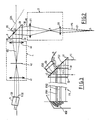
- FIG. 2 a first embodiment of the device according to the invention.
- the arrangement of the various constituent elements of this device, represented in this FIG. 2, is that used by the applicant for the development of the invention.
- the numerical values provided below are of course only for information. They are also provided with an average relative uncertainty of around 5%. It goes without saying that this first embodiment of the device makes it possible to illustrate the general principle of the invention.
- the light source S is a light-emitting diode of the type manufactured by the Japanese company STANLEY. This light emitting diode has an opening angle of 9 degrees and emits a wave whose wavelength is between about 0.62 and about 0.71 microns. This light source therefore has a narrow spectrum.
- a light emitting diode is particularly advantageous in this application compared to laser diodes for example. Indeed the latter are sensitive to sudden variations in the voltage of their power supply which can destroy them and it is therefore necessary to conceive a stabilized power supply for the use of such laser diodes. In addition, their output power depends on the temperature and their lifetime decreases exponentially with increasing temperature. It is therefore necessary to further provide a temperature stabilization system. These precautions for use have led the Applicant to prefer the use of a light-emitting diode which is easy to use, very resistant and consumes little.
- the first optical device 2 comprises a first converging spherical lens 20 with a diameter of 2.4 cm, the optical center of which is located 9 cm from the light source S and the focal distance of which is 2 cm.
- the first optical device 2 also comprises a second converging spherical lens 21, with a diameter of 4 cm, located 8.5 cm from the first converging lens 20. Its focal distance is 5 cm.
- the source beam FS arriving on the first converging lens 20 converges at a point A constituting a substantially point auxiliary source. This auxiliary source A is located 2.6 cm from the optical center of the first spherical lens 20.
- the distance separating the auxiliary source A from the optical center of the second spherical lens 21 is greater than the focal distance of the latter.
- the reasons for this arrangement will be explained below.
- the optical device 2 therefore produces at the output of the second spherical lens 21 the incident beam FI.
- the light source S and the respective optical centers of the first and second converging lenses are aligned along a first optical axis 01.
- the transparent homogeneous medium 3 is a prism of right-angled triangular cross section whose two intersecting perpendicular sides respectively constitute an input diopter 30 and an output diopter 32.
- the side joining the two perpendicular sides 30 and 32 constitutes the bearing surface 31 on which the ED fingerprint is in contact.
- the optical axis 01 is substantially perpendicular to the plane dioptre 30 and the bearing surface 31 is inclined at an angle of 45 degrees relative to this optical axis 01.
- the point of competition 0 of the optical axis 01 and the bearing surface 31 is located at 4 cm from the optical center of the second converging spherical lens 21.
- This prism is made of glass with an optical index equal to approximately 1.5.
- the bearing surface 31 of the prism is large enough to be able to support the finger D.
- the second optical device 4 Downstream of this prism is the second optical device 4.
- This second optical device comprises a Convergent cylindrical lens 40, located 3.5 cm from point 0, the longitudinal geometric axis of which is substantially orthogonal to the optical plane.
- This cylindrical lens will therefore act only on an object situated in a plane parallel to the optical plane, and will have no effect on an object situated in a plane perpendicular to this optical plane.
- the cylindrical lens 40 has a focal distance of 8 cm, greater than the maximum distance separating its optical axis from the relief surface, and provides a virtual image ED1.
- the second optical device 4 also comprises downstream of this cylindrical lens 40, a converging spherical lens 41 whose optical center is located 10 cm from the cylindrical lens 40.
- This spherical lens has a focal distance of 4 cm, and a diameter of 3.15 cm.
- the optical center of this spherical lens is of course located on the optical axis 02 which also intersects the optical axis of the cylindrical lens 40.
- This spatial filter consists of a slit-shaped mask of adjustable width which can go up to 3 mm and a height of 1 cm. The height being of course a dimension taken in the plane perpendicular to the optical plane. The plane of this slot is located 4.3 cm from the optical center of the converging spherical lens 41.
- the image ED2 of the fingerprint ED formed by this second optical device is in a plane whose point of intersection with the optical axis 02 is approximately 5.5 cm from the optical center of the converging spherical lens 41.
- the trace of the plane of the image ED2 on the optical plane is inclined by an angle a .
- a CCD matrix 50 forming part of a conventional CCD receiver.
- the dimensions of this CCD matrix are approximately 8.8 mm x 6.6 mm.
- the light-emitting diode S therefore sends the source beam FS on the first converging spherical lens 20.
- the light-emitting diode is not a coherent source, but, by compared to filament lamps, the light beam emitted is very directive and of limited spectrum.
- the spherical lens 20 makes the source beam converge at a point A which thus constitutes a substantially point source from which the incident beam FI comes. As point A is located at a distance greater than the focal distance of the spherical lens 21, the incident beam FI is slightly convergent at the output of the first optical device 2.
- the light source has the advantage of being economical and of not requiring the precautions for use explained above for the laser diodes, it has another advantage compared to the laser diodes.
- the source beam of the latter is divergent and asymmetrical. There is also an elliptical section, depending on the models used, this divergence can vary between 10 x 25 degrees and 30 x 40 degrees. It is therefore necessary to use wide aperture lenses to create a substantially point source which can be disadvantageous in particular for the bulk.
- the fingerprint ED has a succession of recesses CED and projections SED.
- the projections SED are in contact with the bearing surface 31 while the recesses are not.
- a glass-air interface is therefore obtained, whereas at the level of the projections of this fingerprint, a glass-skin interface is obtained.
- the inclination of the bearing face 31, the angle of incidence of the incident beam FI and the refraction index of the prism are such that a part FI1 of the incident beam FI arriving on the bearing surface at level d '' a glass-air interface is totally reflected in a reflected beam chi FR1.
- a part FI2 of the incident beam FI arriving on the bearing face in contact with a glass-skin interface is partly, or even totally, absorbed into the skin, thus creating a reflected beam FR2 having much less light intensity than the FR1 beam.
- All of these beams FR1 and FR2 comprise an EDO pattern corresponding to the fingerprint ED and obtained by reflection of the incident beam on the bearing surface. This EDO pattern has an anamorphosis due to the inclination of the support surface.
- All of the beams FR1 and FR2 after passing through the optical device 4, not shown in FIG. 3, will form the image ED2 which will be a succession of dark areas, corresponding to the projections of the fingerprint, and clear, corresponding in the hollow of the fingerprint.
- the EDO pattern corresponding to the ED fingerprint has an anamorphosis, that is to say compression in the optical plane.
- the purpose of the cylindrical lens 40 is therefore to correct this anamorphosis and to produce an ED1 image in which the correct proportions are restored.
- the spherical lens 41 makes it possible in combination with the cylindrical lens 40 to carry out on the one hand the development of the image ED2 and so that the latter is real and compatible with the dimensions of the CCD matrix 50 and on the other hand to straighten the plane of the image ED2 in a direction tending to make it practically parallel to the cross section of the reflected beam which reaches it.
- an angle a equal to about 3.5 degrees.
- the function of the spatial filter 42 introduced between the cylindrical lens and the spherical lens makes it possible to limit the aberrations of sphericity of the beam and allows a gain in sharpness and in contrast of the image ED2.
- the cylindrical lens 40 and the spherical lens 41 constitute correction means capable of compensating for the anamorphosis of the used EDO pattern. born by the inclination of the bearing surface 31 and adapted to straighten the image plane as explained above. Given the geometry used, relatively short focal lengths have been chosen for the cylindrical 40 and spherical 41 lenses. This straightening of the plane of the image upon focusing therefore makes it possible to reduce the tilt a of the receiver 5 and d 'increase the image quality, note that this quality is further improved with a slightly oily fingerprint.
- the spherical lens 20 and the spherical lens 21 of the first optical device 2 constitute means of convergence suitable firstly for making the incident beam converge at point A so as to create a substantially point source and secondly suitable for creating a the incident beam advantageously slightly convergent.
- FIG. 4 we see that there is shown a second embodiment of the device according to the invention for housing it in a compact housing.
- elements analogous or having functions analogous to those represented in FIG. 2 have references, either increased by 100, or assigned with a ', with respect to those they had in FIG. 2. Only the differences between these two figures will be described.
- the first optical device further comprises a total reflection prism 22 interposed between the light source S ′ and the lens 120 as well as another total reflection prism 23 interposed between the lenses 120 and 121.
- the second optical device 4 comprises in the same way, moreover, a total reflection prism 43 interposed between the cylindrical lens 140 and the spatial filter 142.
- the prisms 22 and 23 constitute first return means and the prism 43 constitutes second return means.
- the invention may include variants including the following: -
- the Applicant has observed that the use of such a laser source creates a greater contrast than that caused by the light-emitting diode.
- the Applicant therefore prefers to use the light-emitting diode which gives a lower contrast while being largely sufficient since the background noise of the light source is limited, and which does not require the precautions of job described above.
- the light source can be made up of a laser source if the constraints of use are not considered to be penalizing, - lenses of different focal lengths can be chosen, their mutual arrangement then having to be modified; - the receiver is not limited to a CCD matrix.
Abstract
Description
L'invention concerne la formation d'une image d'une surface en relief en contact avec une surface d'appui d'un milieu transparent homogène. Cette image comporte des zones de coloration différentes représentant les creux et les saillies de la surface en relief.The invention relates to the formation of an image of a raised surface in contact with a bearing surface of a homogeneous transparent medium. This image includes different coloring areas representing the hollows and protrusions of the relief surface.
Au sens de la présente invention, le terme "saillie" représente les parties de la surface en relief en contact avec la surface d'appui, tandis que le terme "creux" représente les parties de cette surface en relief non en contact avec la surface d'appui.In the sense of the present invention, the term "projection" represents the parts of the raised surface in contact with the bearing surface, while the term "hollow" represents the parts of this raised surface not in contact with the surface support.
L'invention convient particulièrement aux empreintes digitales bien qu'elle puisse s'appliquer à toute surface en relief pour laquelle on souhaite différencier les creux des saillies.The invention is particularly suitable for fingerprints although it can be applied to any relief surface for which it is desired to differentiate the hollows from the projections.
Une application particulièrement intéressante de l'invention est l'authentification d'empreintes digitales. Les systèmes actuels d'authentification d'empreintes digitales comprennent un dispositif optique de formation d'une image de l'empreinte à authentifier, associé à un dispositif de traitement informatique de l'image ainsi formée. Ce dispositif informatique saisit l'image formée, la traite et la code pour la comparer à une empreinte digitale de référence codée de façon similaire. S'il y a coïncidence entre l'image formée et la référence il y a authentification.A particularly interesting application of the invention is the authentication of fingerprints. Current fingerprint authentication systems include an optical device for forming an image of the fingerprint to be authenticated, associated with a computer processing device for the image thus formed. This computing device captures the formed image, processes it and codes it to compare it with a similarly coded reference fingerprint. If there is a coincidence between the image formed and the reference, there is authentication.
Un support particulièrement bien adapté à l'enregistrement de ces références est une carte à mémoire. Un utilisateur potentiel introduit sa carte à mémoire dans le système d'authenfication et pose son doigt sur un capteur optique du dispositif optique. Le système compare alors les données présentes dans la carte à celles qu'il extrait de l'image formée par le dispositif optique. Comme l'espace mémoire dans une carte est réduit, le système doit être capable d'y stocker des informations exhaustives sur l'empreinte non ambiguës. En conséquence les logiciels utilisés n'auront de réelle efficacité que grâce à une excellente qualité de l'image formée.A medium particularly well suited for recording these references is a memory card. A potential user inserts his memory card into the authentication system and places his finger on an optical sensor of the optical device. The system then compares the data present in the card with that which it extracts from the image formed by the optical device. As the memory space in a card is reduced, the system must be able to store therein comprehensive information on the unambiguous footprint. Consequently, the software used will only have real efficiency thanks to the excellent quality of the image formed.
Les dispositifs optiques actuels comprennent généralement une source lumineuse générant un faisceau lumineux, suivie d'une lentille convergente destinée à produire un faisceau incident. Ce faisceau incident pénètre à l'intérieur d'un milieu homogène transparent pour venir se réfléchir sur une surface d'appui sur laquelle la surface en relief est en contact. Cette surface d'appui est inclinée par rapport à la direction d'incidence de façon à réfléchir totalement les parties du faisceau incident qui frappent la surface d'appui au niveau des creux, les parties du faisceau incident qui frappent la surface d'appui au niveau des saillies étant en partie absorbées dans la peau. Le faisceau réfléchi sort du milieu transparent et traverse une lentille convergente destinée à la mise au point de l'image de la surface en relief.Current optical devices generally include a light source generating a light beam, followed by a converging lens intended to produce an incident beam. This incident beam penetrates inside a homogeneous transparent medium to come to be reflected on a bearing surface on which the raised surface is in contact. This bearing surface is inclined relative to the direction of incidence so as to completely reflect the parts of the incident beam which strike the bearing surface at the level of the recesses, the parts of the incident beam which strike the bearing surface at level of the projections being partly absorbed into the skin. The reflected beam leaves the transparent medium and passes through a converging lens intended for the development of the image of the relief surface.
Plusieurs inconvénients résultent d'un tel dispositif. Le faisceau réfléchi l'est sous un angle identique à l'angle d'incidence si bien que le plan de formation de l'image obtenue n'est pas parallèle à la section droite de ce faisceau, mais incliné de l'angle d'incidence. Si l'on utilise une caméra, par exemple munie d'une matrice à transfert de charge (CCD"charge coupled device"), il faut orienter cette matrice convenablement pour récupérer le plan image. Cependant, lorsque l'objectif de la caméra est long il y a perte de lumière du faisceau réfléchi à l'intérieur de l'objectif ce qui se traduit par un éclairage non uniforme et des difficultés de mise au point.Several drawbacks result from such a device. The reflected beam is at an angle identical to the angle of incidence so that the plane of formation of the image obtained is not parallel to the cross section of this beam, but inclined by the angle of impact. If a camera is used, for example provided with a charge coupled device matrix (CCD), it is necessary to orient this matrix suitably to recover the image plane. However, when the camera lens is long, there is a loss of light from the beam reflected inside the lens, which results in non-uniform lighting and focusing difficulties.
En outre, puisque le plan image est incliné par rapport à la section droite du faisceau réfléchi qui l'atteint, la caméra restitue une image qui semble comprimée latéralement. Ainsi la fréquence des crêtes, par exemple, a augmenté suivant une seule direction. Si l'empreinte à comparer a tourné par rapport à l'empreinte de référence, la compression fait que, même après correction de la rotation, les deux images venant pourtant du même doigt paraîtront toujours différentes d'où des erreurs possibles à l'authentification.In addition, since the image plane is inclined relative to the cross section of the reflected beam which reaches it, the camera reproduces an image which appears to be compressed laterally. So the frequency of peaks, for example, increased according to one direction. If the fingerprint to be compared has rotated with respect to the reference fingerprint, the compression means that, even after correcting the rotation, the two images nevertheless coming from the same finger will always appear different, hence possible errors in authentication .
Pour pallier ces inconvénients on peut utiliser des milieux transparents à embossage, ou en forme de tuile. La surface d'appui n'est pas plane mais elle épouse la courbure du doigt. Cependant, le plan image se trouvant sur une surface courbe, on ne peut pas faire de mise au point statique; il faut donc utiliser nécessairement une méthode de balayage mécanique ce qui rend le système délicat à synchroniser et trop lent.To overcome these drawbacks, transparent embossing media or those in the form of a tile can be used. The bearing surface is not flat but it follows the curvature of the finger. However, the image plane being on a curved surface, it is not possible to focus statically; it is therefore necessary to use a mechanical scanning method which makes the system difficult to synchronize and too slow.
De plus, les milieux transparents possédant une surface d'appui sensiblement plane nécessitent un éclairage puissant quand la source utilisée n'est pas cohérente. Généralement on utilise des lampes classiques à filament qui ne sont pas des sources ponctuelles mais des sources étendues et peu directives. On obtient alors un éclairement non uniforme avec de fortes variations de contrastes dans l'image obtenue.In addition, transparent media having a substantially flat bearing surface require powerful lighting when the source used is not coherent. Generally, conventional filament lamps are used which are not point sources but extensive and poorly directed sources. This gives a non-uniform illumination with strong variations in contrast in the image obtained.
La présente invention vient apporter une amélioration de l'image obtenue dans des dispositifs utilisant des milieux transparents possédant une surface d'appui sensiblement plane.The present invention provides an improvement in the image obtained in devices using transparent media having a substantially planar support surface.
Un but de l'invention est de corriger l'effet de compression latérale occasionné par l'inclinaison de la surface d'appui et de redresser le plan image dans une direction tendant à le rendre parallèle à la section droite du faisceau réfléchi qui l'atteint.An object of the invention is to correct the lateral compression effect caused by the inclination of the support surface and to straighten the image plane in a direction tending to make it parallel to the cross section of the reflected beam which achieved.
Un autre but de l'invention est d'améliorer la netteté et le contraste de l'image obtenue.Another object of the invention is to improve the sharpness and the contrast of the image obtained.
L'invention a encore pour but d'utiliser une source lumineuse économique n'exigeant pas de précautions particulières d'emploi et n'occasionnant pas de fortes variations de contrastes dans l'image.Another object of the invention is to use a light source economical requiring no special precautions for use and not causing large variations in contrast in the image.
Un autre but de l'invention est de limiter les aberrations de sphéricité occasionnées par le dispositif de façon à améliorer encore la netteté et le contraste de l'image obtenue.Another object of the invention is to limit the aberrations of sphericity caused by the device so as to further improve the sharpness and the contrast of the image obtained.
L'invention a donc pour objet un dispositif de formation d'une image d'une surface en relief, notamment une empreinte digitale, comprenant :
- une source lumineuse générant un faisceau source lumineux,
- une premier montage optique produisant un faisceau incident à partir dudit faisceau source,
- un milieu homogène transparent possédant un dioptre d'entrée par lequel le faisceau incident pénètre à l'intérieur dudit milieu selon une direction principale d'incidence, une surface d'appui sensiblement plane sur laquelle la surface en relief est en contact, cette surface d'appui étant inclinée relativement à la direction principale d'incidence de façon à réfléchir totalement une partie du faisceau incident, le faisceau réfléchi sortant du milieu selon une direction principale de réflexion par l'intermédiaire d'un dioptre de sortie et comprenant un motif correspondant à ladite surface en relief, avec une anamorphose occasionnée par l'inclinaison de la surface d'appui,
- un deuxième montage optique recevant le faisceau réfléchi et propre à former ladite image, caractérisé en ce que la source lumineuse a un spectre étroit
- en ce que le premier dispositif optique comporte des moyens de convergence propres à faire converger le faisceau source en un point constituant une source auxiliaire sensiblement ponctuelle et
- en ce que le deuxième dispositif optique comporte des moyens de correction propres à redresser le plan de ladite image dans une direction tendant à le rendre parallèle à une section droite du faisceau réfléchi qui l'atteint, ces moyens de correction étant en outre propres à compenser l'anamorphose dudit motif.The subject of the invention is therefore a device for forming an image of a raised surface, in particular a fingerprint, comprising:
- a light source generating a light source beam,
- a first optical assembly producing an incident beam from said source beam,
a homogeneous transparent medium having an input diopter through which the incident beam penetrates inside said medium in a main direction of incidence, a substantially flat bearing surface on which the raised surface is in contact, this surface support being inclined relative to the main direction of incidence so as to totally reflect part of the incident beam, the reflected beam leaving the medium in a main direction of reflection via an exit diopter and comprising a pattern corresponding to said relief surface, with an anamorphosis caused by the inclination of the bearing surface,
- a second optical assembly receiving the reflected beam and suitable for forming said image, characterized in that the light source has a narrow spectrum
- in that the first optical device comprises means of convergence capable of making the source beam converge at a point constituting an auxiliary source substantially punctual and
- in that the second optical device comprises correction means suitable for straightening the plane of said image in a direction tending to make it parallel to a cross section of the reflected beam which reaches it, these correction means being further suitable for compensate for the anamorphosis of said pattern.
Selon un mode de réalisation de l'invention, le plan contenant les directions principales d'incidence et de réflexion, dit plan optique, est sensiblement perpendiculaire à la surface d'appui et les moyens de correction comprennent avantageusement une lentille cylindrique convergente dont l'axe géométrique longitudinal est sensiblement orthogonal audit plan optique.According to one embodiment of the invention, the plane containing the main directions of incidence and reflection, called the optical plane, is substantially perpendicular to the bearing surface and the correction means advantageously comprise a convergent cylindrical lens whose longitudinal geometric axis is substantially orthogonal to said optical plane.
De préférence, la distance focale de la lentille cylindrique est supérieure à la distance maximale séparant son centre optique de la surface d'appui et les moyens de correction comprennent en outre de préférence, une lentille sphérique convergente placée en aval de la lentille cylindrique.Preferably, the focal distance of the cylindrical lens is greater than the maximum distance separating its optical center from the bearing surface and the correction means preferably further comprise a converging spherical lens placed downstream of the cylindrical lens.
Dans un but d'amélioration de la netteté de l'image, les moyens de correction peuvent comprendre un filtre spatial disposé au niveau du segment de convergence de la lentille cylindrique.In order to improve the sharpness of the image, the correction means can comprise a spatial filter placed at the level of the convergence segment of the cylindrical lens.
Selon un mode de réalisation de l'invention, les moyens de convergence comprennent une première lentille sphérique convergente propre à faire converger le faisceau source au point constituant la source auxiliaire, cette première lentille sphérique convergente étant suivie d'une deuxième lentille sphérique convergente située à une distance de la source auxiliaire au moins égale à sa distance focale.According to one embodiment of the invention, the convergence means comprise a first converging spherical lens capable of making the source beam converge at the point constituting the auxiliary source, this first converging spherical lens being followed by a second converging spherical lens located at a distance from the auxiliary source at least equal to its focal distance.
Très avantageusement, la source lumineuse est une diode électroluminescente.Very advantageously, the light source is a light-emitting diode.
Selon un mode préféré de réalisation, le milieu homogène transparent est un prisme de section droite triangulaire rectangle, dont les deux côtés perpendiculaires sécants constituent respectivement les dioptre d'entrée et de sortie et dont le côté joignant les deux côtés perpendiculaires sécants constitue la surface d'appui, les dioptres d'entrée et de sortie étant respectivement sensiblement parallèles aux sections droites des faisceaux incident et réfléchi qui les traversent.According to a preferred embodiment, the transparent homogeneous medium is a prism of right-angled triangular cross section, the two perpendicular secant sides of which constitute the input and output diopter respectively and the side joining the two perpendicular secant sides constitutes the surface d 'support, the input and output diopters being respectively substantially parallel to the cross sections of the incident and reflected beams passing through them.
Dans un autre mode de réalisation de l'invention, les premier et deuxième montages optiques comprennent respectivement des premiers et deuxièmes moyens de renvoi des faisceaux incident et réfléchi les traversant. Ainsi il est possible de loger le dispositif selon l'invention dans un boîtier compact.In another embodiment of the invention, the first and second optical assemblies respectively comprise first and second means for returning the incident and reflected beams passing through them. Thus it is possible to house the device according to the invention in a compact housing.
D'autres avantages et caractéristiques de l'invention apparaîtront à la lecture de la description détaillée ci-après et des dessins annexés sur lesquels :
- - la figure 1 est un synoptique schématique du dispositif selon l'invention,
- - la figure 2 est une vue de dessus schématique d'un premier mode de réalisation du dispositif selon l'invention,
- - la figure 3 est une représentation schématique illustrant la réflexion du faisceau incident, et,
- - la figure 4 est une représentation schématique d'un second mode de réalisation du dispositif selon l'invention.
- FIG. 1 is a schematic block diagram of the device according to the invention,
- FIG. 2 is a schematic top view of a first embodiment of the device according to the invention,
- FIG. 3 is a schematic representation illustrating the reflection of the incident beam, and,
- - Figure 4 is a schematic representation of a second embodiment of the device according to the invention.
Les dessins comportant pour l'essentiel des éléments de caractère certain font partie intégrante de la description. A ce titre ils pourront servir non seulement à mieux faire comprendre la description détaillée ci-après mais aussi contribuer le cas échéant à la définition de l'invention.The drawings essentially comprising elements of a certain character form an integral part of the description. As such, they can be used not only to better understand the detailed description below but also to contribute, if necessary, to the definition of the invention.
En se référant à la figure 1, on voit qu'un dispositif 1 selon l'invention, comprend de façon générale une source lumineuse S générant un faisceau source lumineux FS. Un premier montage optique 2 produit un faisceau incident FI à partir du faisceau source FS. Ce faisceau incident FI pénètre à l'intérieur d'un milieu homogène transparent 3 possédant une surface d'appui sur laquelle est en contact l'empreinte digitale ED d'un doigt D. Ainsi qu'il sera expliqué ci-après, le faisceau incident FI se réfléchit sur cette surface d'appui selon un faisceau réfléchi FR qui pénètre dans un deuxième dispositif optique 4 lequel forme une image ED2 de l'empreinte digitale ED. Cette image ED2 est reçue sur un récepteur 5.Referring to FIG. 1, it can be seen that a
On va maintenant décrire en se référant plus particulièrement à la figure 2, un premier mode de réalisation du dispositif selon l'invention. La disposition des différents éléments constitutifs de ce dispositif, représentée sur cette figure 2, est celle utilisée par le demandeur pour la mise au point de l'invention. Les valeurs numériques fournies ci-après ne le sont bien entendu qu'à titre indicatif. Elles sont de plus fournies avec une incertitude relative moyenne de 5% environ. Il va de soi que ce premier mode de réalisation du dispositif permet d'illustrer le principe général de l'invention.We will now describe, with particular reference to FIG. 2, a first embodiment of the device according to the invention. The arrangement of the various constituent elements of this device, represented in this FIG. 2, is that used by the applicant for the development of the invention. The numerical values provided below are of course only for information. They are also provided with an average relative uncertainty of around 5%. It goes without saying that this first embodiment of the device makes it possible to illustrate the general principle of the invention.
La source lumineuse S est une diode électroluminescente du type de celles fabriquées par la société japonaise STANLEY. Cette diode électroluminescente a un angle d'ouverture de 9 degrés et émet une onde dont la longueur d'onde est comprise entre environ 0,62 et environ 0,71 micron. Cette source lumineuse a donc un spectre étroit.The light source S is a light-emitting diode of the type manufactured by the Japanese company STANLEY. This light emitting diode has an opening angle of 9 degrees and emits a wave whose wavelength is between about 0.62 and about 0.71 microns. This light source therefore has a narrow spectrum.
L'utilisation d'une diode électroluminescente est particulièrement avantageuse dans cette application par rapport à des diodes laser par exemple. En effet ces dernières sont sensibles aux brusques variations de tension de leur alimentation ce qui peut les détruire et il faut donc concevoir une alimentation stabilisée pour l'utilisation de telles diodes laser. De plus, leur puissance de sortie dépend de la température et leur durée de vie décroît exponentiellement avec l'augmentation de la température. Il est donc nécessaire de prévoir en outre un système de stabilisation en température. Ces précautions d'emploi ont conduit le Demandeur à préférer l'utilisation d'une diode électroluminescente facile d'emploi, très résistante et consommant peu.The use of a light emitting diode is particularly advantageous in this application compared to laser diodes for example. Indeed the latter are sensitive to sudden variations in the voltage of their power supply which can destroy them and it is therefore necessary to conceive a stabilized power supply for the use of such laser diodes. In addition, their output power depends on the temperature and their lifetime decreases exponentially with increasing temperature. It is therefore necessary to further provide a temperature stabilization system. These precautions for use have led the Applicant to prefer the use of a light-emitting diode which is easy to use, very resistant and consumes little.
Le premier dispositif optique 2 comprend une première lentille sphérique convergente 20 d'un diamètre de 2,4 cm, dont le centre optique est situé à 9 cm de la source lumineuse S et dont la distance focale est de 2 cm. Le premier dispositif optique 2 comprend également une deuxième lentille sphérique convergente 21, d'un diamètre de 4 cm, située à 8,5 cm de la première lentille convergente 20. Sa distance focale est de 5 cm. Le faisceau source FS arrivant sur la première lentille convergente 20 converge en un point A constituant une source auxiliaire sensiblement ponctuelle. Cette source auxiliaire A est située à 2,6 cm du centre optique de la première lentille sphérique 20. Ainsi il convient de remarquer que la distance séparant la source auxiliaire A du centre optique de la deuxième lentille sphérique 21 est supérieure à la distance focale de cette dernière. Les raisons de cet agencement seront expliquées ci-après. Le dispositif optique 2 produit donc à la sortie de la deuxième lentille sphérique 21 le faisceau incident FI. La source lumineuse S et les centres optiques respectifs des première et deuxième lentilles convergentes sont alignés selon un premier axe optique 01.The first
Le milieu homogène transparent 3 est un prisme de section droite triangulaire rectangle dont les deux côté perpendiculaires sécants constituent respectivement un dioptre d'entrée 30 et un dioptre de sortie 32. Le côté joignant les deux côtés perpendiculaires 30 et 32 constitue la surface d'appui 31 sur laquelle est en contact l'empreinte digitale ED. L'axe optique 01 est sensiblement perpendiculaire au dioptre plan 30 et la surface d'appui 31 est inclinée d'un angle de 45 degrés par rapport à cet axe optique 01. Le point de concours 0 de l'axe optique 01 et de la surface d'appui 31 est situé à 4 cm du centre optique de la deuxième lentille sphérique convergente 21. Ce prisme est en verre avec un indice optique égal à environ 1,5. La surface d'appui 31 du prisme est suffisamment grande pour pouvoir supporter le doigt D.The transparent homogeneous medium 3 is a prism of right-angled triangular cross section whose two intersecting perpendicular sides respectively constitute an
En aval de ce prisme se trouve le deuxième dispositif optique 4. Celui-ci possède un deuxième axe optique 02 coplanaire avec le premier axe optique 01, ce plan étant dit plan optique, et concourant également au point 0. Ce deuxième dispositif optique comprend une lentille cylindrique convergente 40, située à 3,5 cm du point 0, dont l'axe géométrique longitudinal est sensiblement orthogonal au plan optique. Cette lentille cylindrique n'agira donc que sur un objet situé dans un plan parallèle au plan optique, et n'aura aucun effet sur un objet situé dans un plan perpendiculaire à ce plan optique. La lentille cylindrique 40 a une distance focale de 8 cm, supérieure à la distance maximale séparant son axe optique de la surface en relief, et fournit une image virtuelle ED1.Downstream of this prism is the second
Le deuxième dispositif optique 4 comprend également en aval de cette lentille cylindrique 40, une lentille sphérique convergente 41 dont le centre optique est situé à 10 cm de la lentille cylindrique 40. Cette lentille sphérique a une distance focale de 4 cm, et un diamètre de 3,15 cm. Le centre optique de cette lentille sphérique est bien entendu situé sur l'axe optique 02 qui coupe également l'axe optique de la lentille cylindrique 40.The second
Entre la lentille cylindrique et la lentille sphérique, est disposé au niveau du segment de convergence de la lentille cylindrique 40, un filtre spatial 42 dont les fonctions seront expliquées ci-après. Ce filtre spatial est constitué d'un masque en forme de fente de largeur réglable pouvant aller jusqu'à 3 mm et d'une hauteur de 1 cm. La hauteur étant bien entendu une dimension prise dans le plan perpendiculaire au plan optique. Le plan de cette fente est situé à 4,3 cm du centre optique de la lentille sphérique convergente 41.Between the cylindrical lens and the spherical lens, is disposed at the level of the convergence segment of the
L'image ED2 de l'empreinte digitale ED formée par ce deuxième dispositif optique est dans un plan dont le point d'intersection avec l'axe optique 02 se trouve à environ 5,5 cm du centre optique de la lentille sphérique convergente 41. La trace du plan de l'image ED2 sur le plan optique est inclinée d'un angle a.The image ED2 of the fingerprint ED formed by this second optical device is in a plane whose point of intersection with the
Dans le plan de formation de l'image ED2 est placée une matrice CCD 50 faisant partie d'un récepteur CCD classique. Les dimensions de cette matrice CCD sont de 8,8 mm x 6,6 mm environ.In the ED2 image formation plane is placed a
Le fonctionnement de ce dispositif va maintenant être décrit en se référant également à la figure 3. La diode électroluminescente S envoit donc le faisceau source FS sur la première lentille sphérique convergente 20. La diode électroluminescente n'est pas une source cohérente, mais, par rapport aux lampes à filament, le faisceau lumineux émis est très directif et de spectre limité. La lentille sphérique 20 fait converger le faisceau source en un point A qui constitue ainsi une source sensiblement ponctuelle d'où est issu le faisceau incident FI. Comme le point A est situé à une distance supérieure à la distance focale de la lentille sphérique 21, le faisceau incident FI est légèrement convergent à la sortie du premier dispositif optique 2. Une section droite de ce faisceau incident, située entre la lentille 21 et le dioptre d'entrée 30 à 1 cm du dioptre 30, est un disque sensiblement parallèle au dioptre plan d'un diamètre de 3 cm environ. Par suite de la convergence, la section droite du faisceau réfléchi sortant par le dioptre de sortie 32, prise sur la lentille cylindrique 40, est un disque d'un diamètre sensiblement égal à 2 cm.The operation of this device will now be described with reference also to FIG. 3. The light-emitting diode S therefore sends the source beam FS on the first converging
Outre le fait que la source lumineuse a l'avantage d'être économique et de ne pas exiger les précautions d'emploi explicitées ci-avant pour les diodes laser, elle présente un autre intérêt par rapport aux diodes laser. En effet le faisceau source de ces dernières est divergent et asymétrique. Il est de plus de section elliptique.Selon les modèles utilisés cette divergence peut varier entre 10 x 25 degrés et 30 x 40 degrés. Il faut donc utiliser des lentilles de grande ouverture pour créer une source sensiblement ponctuelle ce qui peut être pénalisant notamment pour l'encombrement.Besides the fact that the light source has the advantage of being economical and of not requiring the precautions for use explained above for the laser diodes, it has another advantage compared to the laser diodes. Indeed, the source beam of the latter is divergent and asymmetrical. There is also an elliptical section, depending on the models used, this divergence can vary between 10 x 25 degrees and 30 x 40 degrees. It is therefore necessary to use wide aperture lenses to create a substantially point source which can be disadvantageous in particular for the bulk.
Le Demandeur a remarqué de façon surprenante que ce caractère légèrement convergent du faisceau incident permet d'obtenir une meilleure qualité de l'image ED2. Les premiers essais du dispositif selon l'invention n'ont pas permis d'obtenir actuellement un faisceau constamment parallèle depuis la sortie de la lentille 21 jusqu'au plan de l'image ED2. Une première explication de ce phénomène serait liée au caractère faiblement cohérent de la source lumineuse S. Cependant l'obtention d'un tel faisceau parallèle n'est pas à exclure en modifiant l'agencement du premier dispositif optique 2 (notamment en plaçant le foyer objet de la lentille 21 au point A) dans le cas où la source lumineuse utilisée le permet.The Applicant has surprisingly noticed that this slightly convergent character of the incident beam makes it possible to obtain a better quality of the ED2 image. The first tests of the device according to the invention did not currently make it possible to obtain a beam constantly parallel from the exit of the
On se réfère maintenant plus particulièrement à la figure 3 pour décrire le phénomène de réflexion à l'intérieur du prisme 3. L'empreinte digitale ED présente une succession de creux CED et de saillies SED. Les saillies SED sont en contact avec la surface d'appui 31 alors que les creux ne le sont pas. Au niveau des creux de l'empreinte digitale ED on obtient donc un interface verre-air alors qu'au niveau des saillies de cette empreinte digitale on obtient un interface verre-peau. L'inclinaison de la face d'appui 31, l'angle d'incidence du faisceau incident FI et l'indice de réfraction du prisme sont tels qu'une partie FI1 du faisceau incident FI arrivant sur la surface d'appui au niveau d'un interface verre-air est réfléchie totalement en un faisceau réflé chi FR1. Par contre une partie FI2 du faisceau incident FI arrivant sur la face d'appui au contact d'un interface verre-peau est en partie, voire totalement, absorbée dans la peau, créant ainsi un faisceau réfléchi FR2 ayant beaucoup moins d'intensité lumineuse que le faisceau FR1. L'ensemble de ces faisceaux FR1 et FR2 comprend un motif EDO correspondant à l'empreinte digitale ED et obtenu par réflexion du faisceau incident sur la surface d'appui. Ce motif EDO présente une anamorphose due à l'inclinaison de la surface d'appui. L'ensemble des faisceaux FR1 et FR2 après passage dans le dispositif optique 4, non représenté sur la figure 3, va former l'image ED2 qui sera une succession de zones sombres, correspondant aux saillies de l'empreinte digitale, et claires, correspondant aux creux de l'empreinte digitale.Reference is now made more particularly to FIG. 3 to describe the phenomenon of reflection inside the prism 3. The fingerprint ED has a succession of recesses CED and projections SED. The projections SED are in contact with the bearing
Ainsi qu'il a été expliqué ci-avant le motif EDO correspondant à l'empreinte digitale ED présente ure anamorphose c'est-à-dire une compression dans le plan optique. La lentille cylindrique 40 a donc pour but de corriger cette anamorphose et de produire une image ED1 dans laquelle les justes proportions sont rétablies. La lentille sphérique 41 permet en combinaison avec la lentille cylindrique 40 d'effectuer d'une part la mise au point de l'image ED2 et de façon que celle-ci soit réelle et compatible avec les dimensions de la matrice CCD 50 et d'autre part de redresser le plan de l'image ED2 dans une direction tendant à le rendre pratiquement parallèle à la section droite du faisceau réfléchi qui l'atteint. Ainsi on obtient un angle a égal à environ 3,5 degrés.As has been explained above, the EDO pattern corresponding to the ED fingerprint has an anamorphosis, that is to say compression in the optical plane. The purpose of the
La fonction du filtre spatial 42 introduit entre la lentille cylindrique et la lentille sphérique permet de limiter les aberrations de sphéricité du faisceau et permet un gain en netteté et en contraste de l'image ED2.The function of the
Ainsi, selon l'invention, la lentille cylindrique 40 et la lentille sphérique 41 constituent des moyens de correction propres à compenser l'anamorphose du motif EDO occasion née par l'inclinaison de la surface d'appui 31 et propres à redresser le plan image comme expliqué ci-avant. Compte tenu de la géométrie utilisée, on a choisi des distances focales relativement courtes pour les lentilles cylindriques 40 et sphériques 41. Ce redressement du plan de l'image à la mise au point permet donc de réduire l'inclinaison a du récepteur 5 et d'augmenter la qualité de l'image, remarque étant faite que l'on améliore encore cette qualité avec une empreinte digitale légèrement grasse.Thus, according to the invention, the
La lentille sphérique 20 et la lentille sphérique 21 du premier dispositif optique 2 constituent des moyens de convergence propres d'une part à faire converger le faisceau incident au point A de façon à créer une source sensiblement ponctuelle et d'autre part propres à créer un faisceau incident avantageusement légèrement convergent.The
Si l'on se réfère maintenant à la figure 4, on voit que l'on a représenté un second mode de réalisation du dispositif selon l'invention permettant de loger celui-ci dans un boîtier compact. Sur cette figure les éléments analogues ou ayant des fonctions analogues à celles représentées sur la figure 2 possèdent des références, soit augmentées de 100, soit affectées d'un', par rapport à celles qu'ils avaient sur la figure 2. Seules les différences entre ces deux figures seront décrites.Referring now to Figure 4, we see that there is shown a second embodiment of the device according to the invention for housing it in a compact housing. In this figure, elements analogous or having functions analogous to those represented in FIG. 2 have references, either increased by 100, or assigned with a ', with respect to those they had in FIG. 2. Only the differences between these two figures will be described.
Le premier dispositif optique comprend en outre un prisme à réflexion totale 22 interposé entre la source lumineuse S′ et la lentille 120 ainsi qu'un autre prisme à réflexion totale 23 interposé entre les lentilles 120 et 121. Le deuxième dispositif optique 4 comprend de la même façon en outre un prisme à réflexion totale 43 interposé entre la lentille cylindrique 140 et le filtre spatial 142. Les prismes 22 et 23 constituent des premiers moyens de renvoi et le prisme 43 constitue des deuxiémes moyens de renvoi. Ces différents moyens de renvoi permettent de diriger dans l'espace les faisceaux sources incident et réfléchi selon des directions différentes afin de réduire l'encombrement des différents éléments constitutifs du dispositif. Ainsi le dispositif de la figure 4 peut-il être logé dans un boîtier cubique de 12 cm de côté non représenté sur cette figure.The first optical device further comprises a
L'invention peut comporter des variantes notamment les suivantes :
- le Demandeur a observé que l'utilisation d'une telle source laser crée un contraste plus important que celui occasionné par la diode électroluminescente. Dans cette application particulière d'authentification d'empreintes, le Demandeur préfère donc utiliser la diode électroluminescente qui donne un contraste moins élevé tout en étant largement suffisant car le bruit de fond de la source lumineuse est limité, et qui ne nécessite pas les précautions d'emploi ci-avant décrites. Cependant, la source lumineuse peut être constituée d'une source laser si les contraintes d'utilisation ne sont pas jugées pénalisantes,
- des lentilles de distances focales différentes peuvent être choisies, leur disposition mutuelle devant alors être modifiée;
- le récepteur n'est pas limité à une matrice CCD.The invention may include variants including the following:
- The Applicant has observed that the use of such a laser source creates a greater contrast than that caused by the light-emitting diode. In this particular fingerprint authentication application, the Applicant therefore prefers to use the light-emitting diode which gives a lower contrast while being largely sufficient since the background noise of the light source is limited, and which does not require the precautions of job described above. However, the light source can be made up of a laser source if the constraints of use are not considered to be penalizing,
- lenses of different focal lengths can be chosen, their mutual arrangement then having to be modified;
- the receiver is not limited to a CCD matrix.
Bien entendu certains des moyens décrits ci-dessus peuvent être omis dans les variantes où ils ne servent pas.Of course, some of the means described above can be omitted in the variants where they are not used.
Claims (10)
- une source lumineuse (SS′) générant un faisceau source lumineux (FS,FS′),
- un premier montage optique (2,102) produisant un faisceau incident (FI,FI′) à partir dudit faisceau source (FS,FS′),
- un milieu homogène transparent (3,103) possédant un dioptre d'entrée (30,130) par lequel le faisceau incident (FI,FI′) pénètre à l'intérieur desdits milieux selon une direction principale d'incidence (01), une surface d'appui (31,131) sensiblement plane sur laquelle la surface en relief (ED) est en contact, cette surface d'appui étant inclinée relativement à la direction principale d'incidence de façon à réfléchir totalement une partie (FR1) du faisceau incident (FI), le faisceau réfléchi (FR,FR′) sortant du milieu (3,103) selon une direction principale de réflexion (02) par l'intermédiaire d'un dioptre de sortie (32,132) et comprenant un motif (EDO) correspondant à ladite surface en relief (ED), avec une anamorphose occasionnée par l'inclinaison de la surface d'appui (31,131),
- un deuxième montage optique (4,104) recevant le faisceau réfléchi (FR,FR′) et propre à former ladite image (ED2), caractérisé en ce que la source lumineuse (S,S′) a un spectre étroit,
- en ce que le premier dispositif optique comporte des moyens de convergence (20,21; 120,121) propres à faire converger le faisceau source (FS,FS′) en un point constituant une source auxiliaire (A) sensiblement ponctuelle et
- en ce que le deuxième dispositif optique (4,104) comporte des moyens de correction (40,41; 140,141) propres à redres ser le plan de l'image (ED2) dans une direction tendant à le rendre parallèle à la section droite du faisceau réfléchi (FR,FR′) qui l'atteint et propres à compenser l'anamorphose dudit motif (EDO).1. Device for forming an image of a relief surface, in particular a fingerprint, comprising:
- a light source (SS ′) generating a light source beam (FS, FS ′),
a first optical assembly (2.102) producing an incident beam (FI, FI ′) from said source beam (FS, FS ′),
- a transparent homogeneous medium (3,103) having an input diopter (30,130) by which the incident beam (FI, FI ′) penetrates inside said mediums in a main direction of incidence (01), a surface of substantially flat support (31,131) on which the raised surface (ED) is in contact, this support surface being inclined relative to the main direction of incidence so as to totally reflect a part (FR1) of the incident beam (FI) , the reflected beam (FR, FR ′) leaving the medium (3,103) in a main direction of reflection (02) via an output diopter (32,132) and comprising a pattern (EDO) corresponding to said surface in relief (ED), with an anamorphosis caused by the inclination of the bearing surface (31,131),
a second optical assembly (4,104) receiving the reflected beam (FR, FR ′) and suitable for forming said image (ED2), characterized in that the light source (S, S ′) has a narrow spectrum,
- in that the first optical device comprises convergence means (20,21; 120,121) suitable for making the source beam converge (FS, FS ′) at a point constituting an auxiliary source (A) substantially punctual and
- in that the second optical device (4,104) comprises correction means (40,41; 140,141) suitable for rectifying ser the plane of the image (ED2) in a direction tending to make it parallel to the cross section of the reflected beam (FR, FR ′) which reaches it and capable of compensating for the anamorphosis of said pattern (EDO).
Applications Claiming Priority (2)
| Application Number | Priority Date | Filing Date | Title |
|---|---|---|---|
| FR8802803A FR2628221B1 (en) | 1988-03-04 | 1988-03-04 | DEVICE FOR FORMING AN IMAGE OF A RELIEF SURFACE, IN PARTICULAR A FINGERPRINT |
| FR8802803 | 1988-03-04 |
Publications (1)
| Publication Number | Publication Date |
|---|---|
| EP0361987A1 true EP0361987A1 (en) | 1990-04-04 |
Family
ID=9363931
Family Applications (1)
| Application Number | Title | Priority Date | Filing Date |
|---|---|---|---|
| EP89400587A Withdrawn EP0361987A1 (en) | 1988-03-04 | 1989-03-02 | Relief surface imaging device, particularly for finger prints |
Country Status (2)
| Country | Link |
|---|---|
| EP (1) | EP0361987A1 (en) |
| FR (1) | FR2628221B1 (en) |
Cited By (5)
| Publication number | Priority date | Publication date | Assignee | Title |
|---|---|---|---|---|
| EP0472769A1 (en) * | 1990-08-30 | 1992-03-04 | Maurer Identifikationssysteme Gmbh | Identification means for thumb- or fingerprints |
| GB2276732A (en) * | 1993-03-31 | 1994-10-05 | Central Research Lab Ltd | Fingerprint imaging |
| WO2001022032A1 (en) * | 1999-09-23 | 2001-03-29 | Lawrence Mullaney | Measuring relief imaged printing plates |
| WO2001031563A1 (en) * | 1999-10-28 | 2001-05-03 | Guardware Systems Informatikai Kft. | Objective lens system |
| WO2020151159A1 (en) * | 2019-01-22 | 2020-07-30 | 深圳市汇顶科技股份有限公司 | Fingerprint recognition apparatus and electronic device |
Citations (3)
| Publication number | Priority date | Publication date | Assignee | Title |
|---|---|---|---|---|
| EP0045913A1 (en) * | 1980-08-11 | 1982-02-17 | Siemens Aktiengesellschaft | Fingerprint sensor delivering an electric signal corresponding to the topographic relief of a finger to be examined |
| EP0045915A1 (en) * | 1980-08-11 | 1982-02-17 | Siemens Aktiengesellschaft | Fingerprint sensor delivering an output signal corresponding to the topographic relief of a finger to be examined |
| DE3421220A1 (en) * | 1984-06-07 | 1985-12-12 | Guenther Mull | DEVICE FOR IMAGING OBJECTS ARRANGED AT AN IMAGE LEVEL |
-
1988
- 1988-03-04 FR FR8802803A patent/FR2628221B1/en not_active Expired - Lifetime
-
1989
- 1989-03-02 EP EP89400587A patent/EP0361987A1/en not_active Withdrawn
Patent Citations (3)
| Publication number | Priority date | Publication date | Assignee | Title |
|---|---|---|---|---|
| EP0045913A1 (en) * | 1980-08-11 | 1982-02-17 | Siemens Aktiengesellschaft | Fingerprint sensor delivering an electric signal corresponding to the topographic relief of a finger to be examined |
| EP0045915A1 (en) * | 1980-08-11 | 1982-02-17 | Siemens Aktiengesellschaft | Fingerprint sensor delivering an output signal corresponding to the topographic relief of a finger to be examined |
| DE3421220A1 (en) * | 1984-06-07 | 1985-12-12 | Guenther Mull | DEVICE FOR IMAGING OBJECTS ARRANGED AT AN IMAGE LEVEL |
Cited By (7)
| Publication number | Priority date | Publication date | Assignee | Title |
|---|---|---|---|---|
| EP0472769A1 (en) * | 1990-08-30 | 1992-03-04 | Maurer Identifikationssysteme Gmbh | Identification means for thumb- or fingerprints |
| GB2276732A (en) * | 1993-03-31 | 1994-10-05 | Central Research Lab Ltd | Fingerprint imaging |
| GB2276732B (en) * | 1993-03-31 | 1995-12-13 | Central Research Lab Ltd | Fingerprint imaging |
| WO2001022032A1 (en) * | 1999-09-23 | 2001-03-29 | Lawrence Mullaney | Measuring relief imaged printing plates |
| WO2001031563A1 (en) * | 1999-10-28 | 2001-05-03 | Guardware Systems Informatikai Kft. | Objective lens system |
| US6934089B1 (en) | 1999-10-28 | 2005-08-23 | Guardware Systems Informatikai Kft. | Objective lens system |
| WO2020151159A1 (en) * | 2019-01-22 | 2020-07-30 | 深圳市汇顶科技股份有限公司 | Fingerprint recognition apparatus and electronic device |
Also Published As
| Publication number | Publication date |
|---|---|
| FR2628221A1 (en) | 1989-09-08 |
| FR2628221B1 (en) | 1990-08-10 |
Similar Documents
| Publication | Publication Date | Title |
|---|---|---|
| US5146102A (en) | Fingerprint image input apparatus including a cylindrical lens | |
| US5629764A (en) | Prism fingerprint sensor using a holographic optical element | |
| EP0644411B1 (en) | Procedure and apparatus for the absolute measurement of the geometrical or optical structure of an optical component | |
| EP0290347B1 (en) | High output signal light, especially for motor vehicles | |
| CH620535A5 (en) | ||
| FR2642530A1 (en) | Focusing mechanism and optical head | |
| FR2558971A1 (en) | APPARATUS FOR FORMING DIGITAL IMPRESSION IMAGES | |
| WO2010146290A1 (en) | Imaging device having a prismatic element | |
| EP0515252A1 (en) | Device for acquisition of the instantaneous angular position of a moving element, and opto-mechanical system comprising such device | |
| EP0361987A1 (en) | Relief surface imaging device, particularly for finger prints | |
| EP0022682A1 (en) | Optical reading head with semi-conductor laser source and device for reading a record carrier by using reflexion, comprising such an optical head | |
| FR2693292A1 (en) | Omnidirectional bar code thumbnail reader, with enlarged reading area. | |
| EP0610640B1 (en) | Portable bar-code reader with extended depth of focus | |
| WO1998047377A1 (en) | Optoelectronic device for image acquisition, in particular of code bars | |
| RU2176097C2 (en) | Optical system forming beam ( variants ) and optical sensor | |
| EP3614305B1 (en) | Authentication by optical index | |
| WO2005038698A1 (en) | Fingerprint-image-forming optical device | |
| FR3110979A1 (en) | LIGHT DISTRIBUTION SYSTEM BASED ON DIFFRACTION NETWORKS | |
| FR2460022A1 (en) | OPTICAL INFORMATION REPRODUCING SYSTEM | |
| EP0135414A1 (en) | Image pick-up optoelectronic sensor | |
| EP1665122B1 (en) | Optical device for forming a fingerprint image | |
| FR2678394A1 (en) | FOCUSING DETECTION DEVICE. | |
| EP2927577B1 (en) | Lighting optic for biometric measurement device | |
| FR2768526A1 (en) | Electro-optical device for reading bar codes | |
| JPH03244092A (en) | Fingerprint image input device |
Legal Events
| Date | Code | Title | Description |
|---|---|---|---|
| PUAI | Public reference made under article 153(3) epc to a published international application that has entered the european phase |
Free format text: ORIGINAL CODE: 0009012 |
|
| AK | Designated contracting states |
Kind code of ref document: A1 Designated state(s): DE GB IT |
|
| 17P | Request for examination filed |
Effective date: 19900705 |
|
| 17Q | First examination report despatched |
Effective date: 19920803 |
|
| STAA | Information on the status of an ep patent application or granted ep patent |
Free format text: STATUS: THE APPLICATION IS DEEMED TO BE WITHDRAWN |
|
| 18D | Application deemed to be withdrawn |
Effective date: 19921215 |