EP0361864B1 - Self-energising disc brakes - Google Patents
Self-energising disc brakes Download PDFInfo
- Publication number
- EP0361864B1 EP0361864B1 EP89309789A EP89309789A EP0361864B1 EP 0361864 B1 EP0361864 B1 EP 0361864B1 EP 89309789 A EP89309789 A EP 89309789A EP 89309789 A EP89309789 A EP 89309789A EP 0361864 B1 EP0361864 B1 EP 0361864B1
- Authority
- EP
- European Patent Office
- Prior art keywords
- brake
- plates
- braking
- input plate
- plate
- Prior art date
- Legal status (The legal status is an assumption and is not a legal conclusion. Google has not performed a legal analysis and makes no representation as to the accuracy of the status listed.)
- Expired - Lifetime
Links
- 125000006850 spacer group Chemical group 0.000 claims description 16
- 230000002093 peripheral effect Effects 0.000 claims description 14
- 150000001875 compounds Chemical class 0.000 claims description 11
- 239000002783 friction material Substances 0.000 claims description 5
- 230000000295 complement effect Effects 0.000 claims description 3
- 239000012530 fluid Substances 0.000 claims description 2
- 230000005540 biological transmission Effects 0.000 description 4
- 230000000712 assembly Effects 0.000 description 2
- 238000000429 assembly Methods 0.000 description 2
- 238000010276 construction Methods 0.000 description 2
- 238000001816 cooling Methods 0.000 description 2
- 230000000694 effects Effects 0.000 description 2
- 230000007246 mechanism Effects 0.000 description 2
- 230000004048 modification Effects 0.000 description 2
- 238000012986 modification Methods 0.000 description 2
- 238000007598 dipping method Methods 0.000 description 1
- 238000003754 machining Methods 0.000 description 1
- 238000004519 manufacturing process Methods 0.000 description 1
- 239000000463 material Substances 0.000 description 1
- 230000002035 prolonged effect Effects 0.000 description 1
- 230000000979 retarding effect Effects 0.000 description 1
- 238000007789 sealing Methods 0.000 description 1
- 238000010008 shearing Methods 0.000 description 1
- 230000002459 sustained effect Effects 0.000 description 1
Images


Classifications
-
- F—MECHANICAL ENGINEERING; LIGHTING; HEATING; WEAPONS; BLASTING
- F16—ENGINEERING ELEMENTS AND UNITS; GENERAL MEASURES FOR PRODUCING AND MAINTAINING EFFECTIVE FUNCTIONING OF MACHINES OR INSTALLATIONS; THERMAL INSULATION IN GENERAL
- F16D—COUPLINGS FOR TRANSMITTING ROTATION; CLUTCHES; BRAKES
- F16D55/00—Brakes with substantially-radial braking surfaces pressed together in axial direction, e.g. disc brakes
- F16D55/02—Brakes with substantially-radial braking surfaces pressed together in axial direction, e.g. disc brakes with axially-movable discs or pads pressed against axially-located rotating members
- F16D55/04—Brakes with substantially-radial braking surfaces pressed together in axial direction, e.g. disc brakes with axially-movable discs or pads pressed against axially-located rotating members by moving discs or pads away from one another against radial walls of drums or cylinders
- F16D55/14—Brakes with substantially-radial braking surfaces pressed together in axial direction, e.g. disc brakes with axially-movable discs or pads pressed against axially-located rotating members by moving discs or pads away from one another against radial walls of drums or cylinders with self-tightening action, e.g. by means of coacting helical surfaces or balls and inclined surfaces
- F16D55/15—Brakes with substantially-radial braking surfaces pressed together in axial direction, e.g. disc brakes with axially-movable discs or pads pressed against axially-located rotating members by moving discs or pads away from one another against radial walls of drums or cylinders with self-tightening action, e.g. by means of coacting helical surfaces or balls and inclined surfaces initiated by means of brake-bands or brake-shoes
-
- F—MECHANICAL ENGINEERING; LIGHTING; HEATING; WEAPONS; BLASTING
- F16—ENGINEERING ELEMENTS AND UNITS; GENERAL MEASURES FOR PRODUCING AND MAINTAINING EFFECTIVE FUNCTIONING OF MACHINES OR INSTALLATIONS; THERMAL INSULATION IN GENERAL
- F16D—COUPLINGS FOR TRANSMITTING ROTATION; CLUTCHES; BRAKES
- F16D65/00—Parts or details
- F16D65/78—Features relating to cooling
- F16D65/84—Features relating to cooling for disc brakes
- F16D65/853—Features relating to cooling for disc brakes with closed cooling system
-
- F—MECHANICAL ENGINEERING; LIGHTING; HEATING; WEAPONS; BLASTING
- F16—ENGINEERING ELEMENTS AND UNITS; GENERAL MEASURES FOR PRODUCING AND MAINTAINING EFFECTIVE FUNCTIONING OF MACHINES OR INSTALLATIONS; THERMAL INSULATION IN GENERAL
- F16D—COUPLINGS FOR TRANSMITTING ROTATION; CLUTCHES; BRAKES
- F16D2125/00—Components of actuators
- F16D2125/18—Mechanical mechanisms
- F16D2125/20—Mechanical mechanisms converting rotation to linear movement or vice versa
- F16D2125/34—Mechanical mechanisms converting rotation to linear movement or vice versa acting in the direction of the axis of rotation
- F16D2125/36—Helical cams, Ball-rotating ramps
Definitions
- This invention relates to self-energising disc brake assemblies of the compound kind in which a pair of pressure plates is located between axially spaced braking surfaces provided in a housing, self-energising camming means is provided between the plates and comprises balls or rollers located in co-operating oppositely inclined angularly spaced recesses provided in adjacent faces of the pressure plates, relative angular movement between the plates causing the plates to move axially apart and into engagement with the braking surfaces due to the balls or rollers riding up ramps defined by the edges of the recesses, and in which one of the plates comprises a driven plate coupled to a rotatable shaft of the brake assembly so as to be axially movable with respect to the shaft but angularly immovable relative thereto, and the other plate comprises an input plate carried from the driven plate by means of the camming means, the compound brake comprising primary braking means provided in the housing to retard rotation of the input plate and a secondary brake formed by the self-energising engagement of the pressure plates with the
- Brakes such as that shown in U-S-A 3 403 753 either need complicated actuation mechanisms for their bands, or have to tolerate scuffing and wear of the band as a result of movement of the axial flange in an axial direction during brake actuation. They are also characterised by their instability, having a high servo factor band brake in series with a high factor ball and ramp brake.
- a self-energising disc brake assembly of the compound kind in which a pair of pressure plates is located between axially spaced braking surfaces provided in a housing, self-energising camming means is provided between the plates and comprises balls or rollers located in co-operating oppositely inclined angularly spaced recesses provided in adjacent faces of the pressure plates, relative angular movement between the plates causing the plates to move axially apart and into engagement with the braking surfaces due to the balls or rollers riding up ramps defined by the edges of the recesses, and in which one of the plates comprises a driven plate coupled to a rotatable shaft of the brake assembly so as to be axially moveable with respect to the shaft but angularly immovable relative thereto, and the other plate comprises an input plate carried from the driven plate by means of the camming means, the compound brake comprising primary braking means provided in the housing to retard rotation of the input plate and a secondary brake formed by the self-energ
- self-energising camming means is provided between the plates and comprises balls or rollers located in co-operating oppositely inclined angularly spaced recesses provided in adjacent faces of the pressure plates, relative angular movement between the plates causing the plates to move axially apart and into engagement with the braking surfaces due to the balls or rollers riding up ramps defined by the edges of the recesses, and in which one of the plates comprises a driven plate coupled to a rotatable shaft of the brake assembly so as to be axially movable with respect to the shaft but angularly immovable relative thereto, and compound brake comprising primary braking means provided in the housing to retard rotation of the input plate and a secondary brake formed by the self-energising engagement of the pressure plates with the braking surfaces, actuation of the secondary brake being effected by application of the primary braking
- the primary braking means co-operates with the radial friction surface to constitute a disc brake.
- Providing a disc brake is far more stable than using a band brake, and provides a more compact assembly.
- a further advantageous feature of the invention is that no wear adjuster is necessary to allow for changes in geometry during the wear life of the brake assembly.
- the torque-transmitting means may comprise an integral part of the input plate and the input plate may simply be of larger diameter than the driven plate.
- Each annular ring preferably has a lining of friction material.
- the primary braking means preferably includes one or more stationary members interposed between adjacent rings and against which the rings may be urged to brake the input plate.
- the primary braking means is of a non-servo nature. This improves the 'feel' characteristics of the brake assembly as a whole, as compared to that experienced with a servo primary braking means.
- a brake assembly with non-servo primary braking means is also less sensitive to changes in the co-efficient of friction of its braking surfaces than an assembly with servo primary braking means.
- the primary braking means may comprise a 'spot' type actuator, akin to a spot caliper.
- the primary braking means comprises an annular piston.
- the brake assembly is then of circular form and there are no asymmetric input loads on the axle shaft.
- the brake assembly is also then of a particularly compact form.
- the primary braking means comprises an annular piston working in a complementary bore in the housing and defining a pressure space in combination with the bore, hydraulic fluid being fed to the pressure space through a supply passage, and the bore and supply passage being defined in a spacer unit which is bolted to the housing.
- the spacer unit preferably has a radial flange which is clamped against the housing.
- the supply passage may be a radially extending passage in the radial flange.
- Preferably the spacer unit defines a braking surface.
- the spacer unit may be clamped between the axle housing and a transmission casing of a vehicle.
- the brake assembly includes a parking brake.
- the parking brake may act on the driven plate or on the input plate and may comprise a belt brake, spot brake, or drum brake.
- a servo brake may be used as the parking brake.
- the pressure plates preferably have linings of friction material for engagement with the braking surfaces.
- the linings of the pressure plates may be secured to the plates themselves or preferably they are provided on separate discs which are keyed to the pressure plates.
- the secondary brake may include one or more friction discs which are keyed to the shaft and are provided with friction linings interposed between the pressure plates and the braking surfaces on the housing, and stationary plates interposed between the pressure plates and the friction discs, and between adjacent friction discs, the stationary plates defining further braking surfaces.
- the pressure plates When the brake assembly is "oil-immersed" the pressure plates may have a pocket, or angularly spaced pockets, adapted to be immersed in a bath of oil and adapted to pick up oil. Slots or grooves may be provided in the friction linings associated with the pressure plates to encourage the flow of oil. The pockets may deliver oil to the slots or grooves. The pockets may be formed in the adjacent surfaces of the pressure plates and may be cast integrally with the plates.
- the brake illustrated in Figures 1 to 3 of the drawings is a rather basic simplified brake which is presented to illustrate the invention clearly.
- the brake comprises a housing 1 having opposed annular radial braking surfaces 2 and 3, a pressure plate assembly 4 located between the braking surfaces and adapted to brake a rotatable axle shaft 5, and primary braking means 6 to initiate actuation of the brake.
- the pressure plate assembly 4 comprises a driven servo plate 7, which is keyed to the axle shaft 5 through splines 8, an input plate 9 carried from the driven plate 7 through a series of balls 10 which are received in pairs of co-operating angularly spaced recesses 11 and 12 provided in the adjacent faces of the pressure plates.
- the recesses 11 and 12 have ramps 11', 12' arranged to provide a self-energising action, in a known manner, for both directions of rotation of the shaft 5.
- Brake release tension return springs 13 are provided to urge the pressure plates towards each other.
- Each of the pressure plates 7,9 carries an annular lining of friction material 14 for engagement with its respective braking surface 2 or 3.
- the pressure plates comprise a secondary brake of which application is initiated automatically when the primary braking means is actuated.
- the input plate 9 is of significantly larger diameter than the driven plate 7 and an annular portion terminating at its outer most peripheral edge projects radially beyond the outer peripheral edge 15 of the driven plate.
- the said annular portion of the input plate 9 comprises torque-transmitting means 16 by which a retarding torque is transmitted to the central part of the input plate 9 in which the recesses 12 are provided.
- the torque-transmitting means 16 defines radial friction surfaces 17 on opposite sides of the plate 9.
- the primary braking means 6 is only shown schematically, but comprises a non-servo spot type hydraulic brake actuator 18 having a piston 19, and a reaction surface 20 towards which the piston 19 is adapted to be urged. Mechanical means for actuating the primary braking means may also be provided.
- the piston 19 and reaction surface 20 are axially spaced on opposite sides of the torque-transmitting means 16.
- the primary braking means 6 is actuated to urge the piston 19 and reaction surface 20 against the radial friction surfaces 17 of the torque-transmitting means 16. This retards rotation of the input plate 9.
- the driven plate 7 is carried around with the shaft 5, the resulting relative angular movement between the pressure plates causes the balls 10 to ride up the ramps 11', 12', urging the input plate and the driven plate axially away from each other.
- the linings 14 are therefore urged against the braking surfaces 2 and 3. This tends further to retard the input plate, with the result that the balls are urged even further up the ramps in a self-energising action.
- the shaft 5 can only be braked by braking the driven plate 7, since the input plate 9 does not touch the shaft.
- the driven plate 7 is braked in two ways: firstly by the torque transmitted to that plate from the input plate through the engagement of the balls 10 with the recesses 11, and secondly by the engagement of the friction lining 14 of the driven plate with the braking surface 2.
- the input plate 9 is of course braked by the braking surface 3 (secondary brake) and by the primary braking means 6 (primary brake).
- the compound brake of Figures 1 to 3 retains reasonably stable "feel" characteristics of a non-servo brake to some extent, but also has the greater stopping power of a servo brake.
- the PV input is that necessary to generate the required torque of the primary braking means alone. (PV is the product of pressure and volume.)
- Figures 4 and 5 illustrate schematically modified brakes similar to that of Figure 1 to 3, but having a parking brake 21 in addition to the primary braking means 6. Similar reference numerals have been used where appropriate to identify common parts.
- the parking brake 21 of Figure 4 is constituted by a shoe brake 22 which acts directly on the driven plate 7. However, in a modification, it could be a band brake.
- the shoe brake 22 is arranged to be self-energising for both directions of rotation of the shaft 5. This, therefore, reduces the required PV for parking.
- the parking brake of Figure 5 is a spot type brake 23 applied to the input plate 9.
- the servo mechanism of the secondary brake applies the secondary brake should the shaft 5 begin to turn after the parking brake 23 has been applied.
- the primary braking means 6 and the parking brake could be one and the same brake.
- the braking torque produced by the secondary brake is substantially proportional to the braking torque applied by the primary braking means.
- the braking torque of the secondary brake of Figures 1 to 5 is therefore significantly greater than the braking torque of the primary braking means.
- Figure 6 shows a modified brake in which the braking torque of the secondary brake is increased in comparison with that of the primary braking means.
- the brake of Figure 6 has a pair of friction discs 24 keyed to the axle shaft 5 and interposed between the pressure plates and their respective braking surfaces 2 and 3.
- the friction discs 24 carry friction linings 26 on their radial surfaces.
- Relatively stationary intermediate plates 27 in the form of annular discs are provided interposed between the friction discs 24 and the pressure plates 7 and 9.
- the stationary plates 27 are keyed to the housing 1 for axial movement by their co-operation with bolts, lugs or pins 28 fixedly screwed into the housing 1.
- Figure 7 shows another embodiment of the invention.
- the input plate 9 is thicker than that of the input plates in the previous embodiments and has a series of splines 30 provided around its outer peripheral edge 15.
- a pair of annular torque-transmitting discs 31 having corresponding splines at their inner peripheral edges are provided surrounding the input plate 9, and the discs 31 are keyed to the outer peripheral edge 15 of the input plate 9 for axial movement only.
- the torque-transmitting discs 31 correspond to the torque-transmitting means 16 of the previous embodiments.
- the primary braking means comprises a hydraulically actuated annular piston 32 received in an annular bore 33 provided in a first part 34 of the housing 1 with seals 35 carried by the piston 32 sealing the piston in the bore 33.
- a second part 36 of the housing is secured to the first part 34 and has a stepped cavity to define the braking surface 2.
- the braking surface 2 is stepped being defined by a radially outer part 2 a against which the adjacent disc 31 reacts, and a radially inner part 2 b against which the driven plate 7 reacts.
- the radially outer part 2 a of the braking surface is approximately aligned with the plane of the centre of the balls 10 when the brake is unactuated.
- An annular relatively stationary intermediate plate 37 is provided interposed between the annular piston 32 and the adjacent torque-transmitting discs 31, and another is provided between the discs 31.
- the stationary plates 37 are keyed for axial movement by their engagement with screw bolts or pins 38 (only one of which is shown) which are screwed into the first part 34 of the housing 1.
- the arrangement of Figure 7 has a greater surface area of contact between its torque-transmitting means that does the arrangement of Figure 1, and has a greater energy capacity.
- the embodiment of Figure 7 has a relatively greater proportion of its overall braking torque contributed by the non-servo primary braking means than does the brake of Figure 1 and can therefore be expected to have better 'feel' characteristics than the brake of Figure 1.
- the feature of the annular piston 32 gives the brake substantial circular symmetry and reduces radial braking stresses.
- FIG 8 shows another embodiment of the invention which is in some ways a combination of features present in Figures 6 and 7, together with further features.
- the brake has primary braking means comprising an annular piston 40 of stepped form which is received in a correspondingly stepped bore 41 provided in a spacer unit 42.
- the spacer unit 42 has a radially projecting peripheral flange 43 which is clamped between complementary abutment surfaces 44 and 45 of an axle housing 46 and a transmission casing 47.
- Bolts 48 extend from the axle housing, through the flange 43 and into the transmission casing to secure the spacer unit 42.
- Seals 35' are provided to seal the piston 40, and to seal the junction of the spacer unit 42 and the axle housing 46 and transmission casing 47.
- the spacer unit 42 has a radially inwardly directed flange 49 which defines the braking surface 2.
- a supply port 50 extends radially through the flange 43 from a pressure space 50' defined between the piston and the spacer unit.
- the pressure plates 7 and 9 do not have integral friction linings. Instead it is more convenient to key lining discs 51 and 52 (similar to the friction discs 24 of Figure 6) to the pressure plates 7 and 9 respectively.
- the lining discs 51 and 52 have friction linings 26'.
- the lining disc 52 is keyed to the input plate 9 at its outer periphery by the co-operation of radially projecting fingers 53 at the outer edge of the lining disc 52 with axial projections 54 of splines 55 provided at the outer peripheral edge of the input plate 9.
- the lining disc 51 is keyed to the driven plate 7 by being keyed to the axle shaft 5 by means of the splines 8.
- the lining disc 51 has a redundant lining 26'. Brake release tension return springs 56 act between the lining discs 51 and 52.
- An additional friction disc 57 keyed to the axle shaft 5 is provided between the lining disc 51 and the braking surface 2.
- a relatively stationary plate 58 is interposed between discs 51 and 57 and is keyed against rotation by its engagement with bolts 59 mounted in flange 49.
- the torque-transmitting means 6 of the brake of Figure 8 comprises an annular torque-transmitting disc 60 which is keyed to the outer peripheral edge of the servo plate by inwardly directed splines 61 which co-operate with the splines 55 of the input plate 9.
- the torque-transmitting disc 60 has friction linings 62.
- An annular torque-taking plate 63 is interposed between the torque-transmitting disc 60 and the annular piston 40.
- the plate 63 is axially cranked at its radially inner portion and is keyed against rotation by its engagement with bolts 59.
- the torque-taking plate 63 prevents the annular piston 40 from receiving torque from the driven plate 7.
- the provision of the bore 41 in a separate spacer unit 42 instead of directly into the housing 1 enables the bore 41 to be machined into a low-cost component. Any flaws in the difficult operation of machining the bore do not ruin the entire housing, but only the relatively cheap spacer unit.
- the spacer unit 42 can be used with a variety of different brake models.
- the embodiment of Figure 9 has relatively stationary plates 70 keyed to the housing 1 and located between each pressure plate and its respective braking surface 2 or 3.
- a further friction disc 71 with friction linings 72 is interposed between each stationary plate 70 and the respective braking surface 2 or 3.
- the servo plate 9 has an annular torque-transmitting disc 73 keyed to its outer peripheral edge for engagement with braking surfaces 74 and 75 provided on the housing and an annular, axially slidable, torque-taking plate 76 respectively.
- the primary braking means acts on the plate 76.
- the pressure plates 7 and 9 have a series of angularly spaced recesses 77 in their outer surfaces. Lining discs 78 having friction linings 79 are keyed to the pressure plates by a series of corresponding axial projections 80 received in the recesses 77. The projections 80 are made by partially shearing the material of the discs 78. Brake release springs 81 act between the lining discs 78.
- the lining disc 78 of the driven pressure plate 7 is keyed to the axle shaft 5, and the driven plate 7 is only keyed to the shaft through its lining disc 78. This simplifies the construction of the driven plate.
- the brake of Figure 9 is an oil-immersed brake, the main reservoir of oil being shown at 82.
- the pressure plates 7 and 9 each have a series of angularly spaced pockets 83 provided at their radially inner regions, and a series of oil circulation slots or grooves 84 is provided in the linings 79 of the lining discs 78 and the further friction discs 71.
- the pockets 83 dip into the reservoir 82 and collect a quantity of cooling oil which is then directed by centrepetal forces to flow from the pocket 83 into the slots or grooves 84 and thence to flow to the friction linings 72 and 79.
- pockets 83 to collect a relatively large volume of oil from the reservoir 82 allows the oil to be released from each pocket into the oil circulation grooves over a large proportion of the rotation cycle of the pressure plates by an appropriate selection of the throttling effect of the relatively narrow slots or grooves emanating from the pockets. A prolonged and sustained cooling effect is achieved, in comparison with simply having slots and grooves dipping periodically into the reservoir 82.
Description
- This invention relates to self-energising disc brake assemblies of the compound kind in which a pair of pressure plates is located between axially spaced braking surfaces provided in a housing, self-energising camming means is provided between the plates and comprises balls or rollers located in co-operating oppositely inclined angularly spaced recesses provided in adjacent faces of the pressure plates, relative angular movement between the plates causing the plates to move axially apart and into engagement with the braking surfaces due to the balls or rollers riding up ramps defined by the edges of the recesses, and in which one of the plates comprises a driven plate coupled to a rotatable shaft of the brake assembly so as to be axially movable with respect to the shaft but angularly immovable relative thereto, and the other plate comprises an input plate carried from the driven plate by means of the camming means, the compound brake comprising primary braking means provided in the housing to retard rotation of the input plate and a secondary brake formed by the self-energising engagement of the pressure plates with the braking surfaces, actuation of the secondary brake being effected by application of the primary braking means to retard the input plate and so cause relative angular movement between the pressure plates causing them to engage the braking surfaces whereby to initiate a self-energising braking action by the secondary brake. Such brake assemblies will hereinafter be referred to as being "of the kind set forth".
- An example of a brake assembly of the kind set forth is shown in US-A- 3 403 753 which discloses such a brake having a servo plate with an axial flange at its outer periphery, and a primary braking means comprising a band brake for application to the axial flange.
- Brakes such as that shown in U-S-A 3 403 753 either need complicated actuation mechanisms for their bands, or have to tolerate scuffing and wear of the band as a result of movement of the axial flange in an axial direction during brake actuation. They are also characterised by their instability, having a high servo factor band brake in series with a high factor ball and ramp brake.
- In GB-A-1 005 382 there is disclosed a self-energising disc brake assembly of the compound kind in which a pair of pressure plates is located between axially spaced braking surfaces provided in a housing, self-energising camming means is provided between the plates and comprises balls or rollers located in co-operating oppositely inclined angularly spaced recesses provided in adjacent faces of the pressure plates, relative angular movement between the plates causing the plates to move axially apart and into engagement with the braking surfaces due to the balls or rollers riding up ramps defined by the edges of the recesses, and in which one of the plates comprises a driven plate coupled to a rotatable shaft of the brake assembly so as to be axially moveable with respect to the shaft but angularly immovable relative thereto, and the other plate comprises an input plate carried from the driven plate by means of the camming means, the compound brake comprising primary braking means provided in the housing to retard rotation of the input plate and a secondary brake formed by the self-energising engagement of the pressure plates with the braking surfaces, actuation of the secondary braking being effected by application of the primary braking means to retard the input plate and so cause relative angular movement between the pressure plates causing them to engage the braking surfaces whereby to initiate a self-energising braking action by the secondary brake; in that torque-transmitting means co-operates with the input plate; the torque-transmitting means extending radially outwards beyond the outer peripheral edge of the driven plate and having a radial friction surface beyond that edge, said primary braking means being adapted to apply a force to the radial friction surface of the torque-transmitting means substantially in an axial direction in order to retard the input plate.
- In US-A-2 256 725 a self-energising disc brake assembly of the compound kind is disclosed which also has these features.
- According to the invention in a self-energising disc brake assembly of the compound kind in which a pair of pressure plates is located between axially spaced braking surfaces provided in a housing, self-energising camming means is provided between the plates and comprises balls or rollers located in co-operating oppositely inclined angularly spaced recesses provided in adjacent faces of the pressure plates, relative angular movement between the plates causing the plates to move axially apart and into engagement with the braking surfaces due to the balls or rollers riding up ramps defined by the edges of the recesses, and in which one of the plates comprises a driven plate coupled to a rotatable shaft of the brake assembly so as to be axially movable with respect to the shaft but angularly immovable relative thereto, and compound brake comprising primary braking means provided in the housing to retard rotation of the input plate and a secondary brake formed by the self-energising engagement of the pressure plates with the braking surfaces, actuation of the secondary brake being effected by application of the primary braking means to retard the input plate and so cause relative angular movement between the pressure plates causing them to engage the braking surfaces whereby to initiate a self-energising braking action by the secondary brake, the torque-transmitting means co-operates with the input plate and is angularly rigid with respect to the input plate, the torque-transmitting means extending radially outwards beyond the outer peripheral edge of the driven plate and having a radial friction surface beyond that edge, said primary braking means being adapted to apply a force to the radial friction surface of the torque-transmitting means substantially in an axial direction in order to retard the input plate, characterised in that the torque-transmitting means comprises a member secured to the input plate, the member comprising one or more annular rings keyed to the outer peripheral edge of the input plate for axial movement relative thereto.
- Conveniently the primary braking means co-operates with the radial friction surface to constitute a disc brake.
- Providing a disc brake is far more stable than using a band brake, and provides a more compact assembly.
- By applying an axial force to the torque-transmitting means problems associated with radial stresses during brake actuation are eliminated.
- A further advantageous feature of the invention is that no wear adjuster is necessary to allow for changes in geometry during the wear life of the brake assembly.
- The torque-transmitting means may comprise an integral part of the input plate and the input plate may simply be of larger diameter than the driven plate.
- Each annular ring preferably has a lining of friction material.
- When the torque-transmitting means comprises two or more annular rings keyed to the input plate the primary braking means preferably includes one or more stationary members interposed between adjacent rings and against which the rings may be urged to brake the input plate.
- Preferably the primary braking means is of a non-servo nature. This improves the 'feel' characteristics of the brake assembly as a whole, as compared to that experienced with a servo primary braking means. A brake assembly with non-servo primary braking means is also less sensitive to changes in the co-efficient of friction of its braking surfaces than an assembly with servo primary braking means.
- The primary braking means may comprise a 'spot' type actuator, akin to a spot caliper. Preferably, however, the primary braking means comprises an annular piston. The brake assembly is then of circular form and there are no asymmetric input loads on the axle shaft. The brake assembly is also then of a particularly compact form.
- In a preferred embodiment the primary braking means comprises an annular piston working in a complementary bore in the housing and defining a pressure space in combination with the bore, hydraulic fluid being fed to the pressure space through a supply passage, and the bore and supply passage being defined in a spacer unit which is bolted to the housing.
- The spacer unit preferably has a radial flange which is clamped against the housing. The supply passage may be a radially extending passage in the radial flange. Preferably the spacer unit defines a braking surface. The spacer unit may be clamped between the axle housing and a transmission casing of a vehicle.
- Preferably the brake assembly includes a parking brake. The parking brake may act on the driven plate or on the input plate and may comprise a belt brake, spot brake, or drum brake. A servo brake may be used as the parking brake.
- The pressure plates preferably have linings of friction material for engagement with the braking surfaces. The linings of the pressure plates may be secured to the plates themselves or preferably they are provided on separate discs which are keyed to the pressure plates.
- The secondary brake may include one or more friction discs which are keyed to the shaft and are provided with friction linings interposed between the pressure plates and the braking surfaces on the housing, and stationary plates interposed between the pressure plates and the friction discs, and between adjacent friction discs, the stationary plates defining further braking surfaces.
- When the brake assembly is "oil-immersed" the pressure plates may have a pocket, or angularly spaced pockets, adapted to be immersed in a bath of oil and adapted to pick up oil. Slots or grooves may be provided in the friction linings associated with the pressure plates to encourage the flow of oil. The pockets may deliver oil to the slots or grooves. The pockets may be formed in the adjacent surfaces of the pressure plates and may be cast integrally with the plates.
- Embodiments of the invention will now be described by way of example only, with reference to the accompanying drawings of which:-
- Figure 1 shows a disc brake in accordance with the invention, with part of its housing removed for clarity;
- Figure 2 is a cross-section on line 2-2 of Figure 1;
- Figure 3 shows a cross-section on arc 3-3 of Figure 1 when the brake assembly is actuated;
- Figure 4 is a section similar to Figure 2 but illustrating another brake;
- Figure 5 is a section similar to Figure 4 but showing a modified brake;
- Figure 6 is a section through yet another brake;
- Figure 7 is a section through a brake in which the primary braking means includes an annular hydraulic piston;
- Figure 8 is a section through a brake based on a combination of the brakes illustrated in Figures 6 and 7; and
- Figure 9 shows an oil-immersed brake assembly in accordance with the invention.
- The brake illustrated in Figures 1 to 3 of the drawings is a rather basic simplified brake which is presented to illustrate the invention clearly. The brake comprises a housing 1 having opposed annular
radial braking surfaces pressure plate assembly 4 located between the braking surfaces and adapted to brake arotatable axle shaft 5, and primary braking means 6 to initiate actuation of the brake. - The
pressure plate assembly 4 comprises a drivenservo plate 7, which is keyed to theaxle shaft 5 through splines 8, an input plate 9 carried from the drivenplate 7 through a series ofballs 10 which are received in pairs of co-operating angularly spacedrecesses recesses shaft 5. Brake releasetension return springs 13 are provided to urge the pressure plates towards each other. Each of thepressure plates 7,9 carries an annular lining offriction material 14 for engagement with itsrespective braking surface - The pressure plates comprise a secondary brake of which application is initiated automatically when the primary braking means is actuated.
- The input plate 9 is of significantly larger diameter than the driven
plate 7 and an annular portion terminating at its outer most peripheral edge projects radially beyond the outerperipheral edge 15 of the driven plate. The said annular portion of the input plate 9 comprises torque-transmitting means 16 by which a retarding torque is transmitted to the central part of the input plate 9 in which therecesses 12 are provided. The torque-transmitting means 16 definesradial friction surfaces 17 on opposite sides of the plate 9. - The primary braking means 6 is only shown schematically, but comprises a non-servo spot type
hydraulic brake actuator 18 having apiston 19, and areaction surface 20 towards which thepiston 19 is adapted to be urged. Mechanical means for actuating the primary braking means may also be provided. Thepiston 19 andreaction surface 20 are axially spaced on opposite sides of the torque-transmitting means 16. - To initiate brake actuation the primary braking means 6 is actuated to urge the
piston 19 andreaction surface 20 against theradial friction surfaces 17 of the torque-transmitting means 16. This retards rotation of the input plate 9. However since the drivenplate 7 is carried around with theshaft 5, the resulting relative angular movement between the pressure plates causes theballs 10 to ride up the ramps 11', 12', urging the input plate and the driven plate axially away from each other. Thelinings 14 are therefore urged against thebraking surfaces - The
shaft 5 can only be braked by braking the drivenplate 7, since the input plate 9 does not touch the shaft. The drivenplate 7 is braked in two ways: firstly by the torque transmitted to that plate from the input plate through the engagement of theballs 10 with therecesses 11, and secondly by the engagement of the friction lining 14 of the driven plate with thebraking surface 2. Thus the drivenplate 7 is braked both directly by the secondary brake through the engagement of the drivenplate 7 with thebraking surface 2, and indirectly through the braking of the input plate 9. The input plate 9 is of course braked by the braking surface 3 (secondary brake) and by the primary braking means 6 (primary brake). - The compound brake of Figures 1 to 3 retains reasonably stable "feel" characteristics of a non-servo brake to some extent, but also has the greater stopping power of a servo brake. The PV input is that necessary to generate the required torque of the primary braking means alone. (PV is the product of pressure and volume.)
- Figures 4 and 5 illustrate schematically modified brakes similar to that of Figure 1 to 3, but having a
parking brake 21 in addition to the primary braking means 6. Similar reference numerals have been used where appropriate to identify common parts. - The
parking brake 21 of Figure 4 is constituted by ashoe brake 22 which acts directly on the drivenplate 7. However, in a modification, it could be a band brake. Theshoe brake 22 is arranged to be self-energising for both directions of rotation of theshaft 5. This, therefore, reduces the required PV for parking. - The parking brake of Figure 5 is a
spot type brake 23 applied to the input plate 9. The servo mechanism of the secondary brake applies the secondary brake should theshaft 5 begin to turn after theparking brake 23 has been applied. - In another modification the primary braking means 6 and the parking brake could be one and the same brake.
- In the embodiments described the braking torque produced by the secondary brake is substantially proportional to the braking torque applied by the primary braking means. The braking torque of the secondary brake of Figures 1 to 5 is therefore significantly greater than the braking torque of the primary braking means.
- Figure 6 shows a modified brake in which the braking torque of the secondary brake is increased in comparison with that of the primary braking means. In addition to the structure of the brake of Figures 1 to 3, the brake of Figure 6 has a pair of
friction discs 24 keyed to theaxle shaft 5 and interposed between the pressure plates and theirrespective braking surfaces friction discs 24 carryfriction linings 26 on their radial surfaces. Relatively stationaryintermediate plates 27 in the form of annular discs are provided interposed between thefriction discs 24 and thepressure plates 7 and 9. Thestationary plates 27 are keyed to the housing 1 for axial movement by their co-operation with bolts, lugs or pins 28 fixedly screwed into the housing 1. - The performance of brakes similar to that of Figure 5 can therefore be increased as shown in Figure 6 by providing further friction discs 24 (and stationary plates 27). The torque generated by the secondary brake varies substantially in proportion with the number of
friction discs 24 that the brake has, whilst the input PV applied by the operator remains that required to actuate the primary braking means 6. Thus a brake can be produced with an exceptionally high performance. - Figure 7 shows another embodiment of the invention. In this construction the input plate 9 is thicker than that of the input plates in the previous embodiments and has a series of
splines 30 provided around its outerperipheral edge 15. A pair of annular torque-transmittingdiscs 31 having corresponding splines at their inner peripheral edges are provided surrounding the input plate 9, and thediscs 31 are keyed to the outerperipheral edge 15 of the input plate 9 for axial movement only. The torque-transmittingdiscs 31 correspond to the torque-transmitting means 16 of the previous embodiments. - The primary braking means comprises a hydraulically actuated
annular piston 32 received in anannular bore 33 provided in afirst part 34 of the housing 1 withseals 35 carried by thepiston 32 sealing the piston in thebore 33. Asecond part 36 of the housing is secured to thefirst part 34 and has a stepped cavity to define thebraking surface 2. Thebraking surface 2 is stepped being defined by a radially outer part 2a against which theadjacent disc 31 reacts, and a radiallyinner part 2b against which the drivenplate 7 reacts. The radially outer part 2a of the braking surface is approximately aligned with the plane of the centre of theballs 10 when the brake is unactuated. - An annular relatively stationary
intermediate plate 37 is provided interposed between theannular piston 32 and the adjacent torque-transmittingdiscs 31, and another is provided between thediscs 31. Thestationary plates 37 are keyed for axial movement by their engagement with screw bolts or pins 38 (only one of which is shown) which are screwed into thefirst part 34 of the housing 1. - The arrangement of Figure 7 has a greater surface area of contact between its torque-transmitting means that does the arrangement of Figure 1, and has a greater energy capacity. The embodiment of Figure 7 has a relatively greater proportion of its overall braking torque contributed by the non-servo primary braking means than does the brake of Figure 1 and can therefore be expected to have better 'feel' characteristics than the brake of Figure 1. The feature of the
annular piston 32 gives the brake substantial circular symmetry and reduces radial braking stresses. - Existing brakes which have annular pistons can readily be modified to define compound brakes, similar to that illustrated in Figure 7, by the addition of a secondary brake similar to those described above. The manufacturing process can also be modified relatively easily.
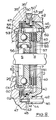
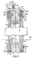
- Figure 8 shows another embodiment of the invention which is in some ways a combination of features present in Figures 6 and 7, together with further features. The brake has primary braking means comprising an
annular piston 40 of stepped form which is received in a correspondingly stepped bore 41 provided in aspacer unit 42. Thespacer unit 42 has a radially projectingperipheral flange 43 which is clamped between complementary abutment surfaces 44 and 45 of anaxle housing 46 and atransmission casing 47.Bolts 48 extend from the axle housing, through theflange 43 and into the transmission casing to secure thespacer unit 42. Seals 35' are provided to seal thepiston 40, and to seal the junction of thespacer unit 42 and theaxle housing 46 andtransmission casing 47. Thespacer unit 42 has a radially inwardly directedflange 49 which defines thebraking surface 2. Asupply port 50 extends radially through theflange 43 from a pressure space 50' defined between the piston and the spacer unit. - The
pressure plates 7 and 9 do not have integral friction linings. Instead it is more convenient tokey lining discs 51 and 52 (similar to thefriction discs 24 of Figure 6) to thepressure plates 7 and 9 respectively. Thelining discs lining disc 52 is keyed to the input plate 9 at its outer periphery by the co-operation of radially projectingfingers 53 at the outer edge of thelining disc 52 withaxial projections 54 ofsplines 55 provided at the outer peripheral edge of the input plate 9. Thelining disc 51 is keyed to the drivenplate 7 by being keyed to theaxle shaft 5 by means of the splines 8. Thelining disc 51 has a redundant lining 26'. Brake release tension return springs 56 act between the liningdiscs - An additional friction disc 57 keyed to the
axle shaft 5 is provided between thelining disc 51 and thebraking surface 2. A relativelystationary plate 58 is interposed betweendiscs 51 and 57 and is keyed against rotation by its engagement withbolts 59 mounted inflange 49. - The torque-transmitting
means 6 of the brake of Figure 8 comprises an annular torque-transmittingdisc 60 which is keyed to the outer peripheral edge of the servo plate by inwardly directedsplines 61 which co-operate with thesplines 55 of the input plate 9. The torque-transmittingdisc 60 hasfriction linings 62. An annular torque-takingplate 63 is interposed between the torque-transmittingdisc 60 and theannular piston 40. Theplate 63 is axially cranked at its radially inner portion and is keyed against rotation by its engagement withbolts 59. The torque-takingplate 63 prevents theannular piston 40 from receiving torque from the drivenplate 7. - The operation of the brake of Figure 8 is similar to that of Figures 6 and 7.
- The provision of the
bore 41 in aseparate spacer unit 42 instead of directly into the housing 1 enables thebore 41 to be machined into a low-cost component. Any flaws in the difficult operation of machining the bore do not ruin the entire housing, but only the relatively cheap spacer unit. In addition thespacer unit 42 can be used with a variety of different brake models. - The embodiment of Figure 9 has relatively
stationary plates 70 keyed to the housing 1 and located between each pressure plate and itsrespective braking surface further friction disc 71 withfriction linings 72 is interposed between eachstationary plate 70 and therespective braking surface disc 73 keyed to its outer peripheral edge for engagement withbraking surfaces plate 76 respectively. The primary braking means (not shown) acts on theplate 76. - The
pressure plates 7 and 9 have a series of angularly spacedrecesses 77 in their outer surfaces. Liningdiscs 78 havingfriction linings 79 are keyed to the pressure plates by a series of correspondingaxial projections 80 received in therecesses 77. Theprojections 80 are made by partially shearing the material of thediscs 78. Brake release springs 81 act between the liningdiscs 78. Thelining disc 78 of the drivenpressure plate 7 is keyed to theaxle shaft 5, and the drivenplate 7 is only keyed to the shaft through itslining disc 78. This simplifies the construction of the driven plate. - The brake of Figure 9 is an oil-immersed brake, the main reservoir of oil being shown at 82. The
pressure plates 7 and 9 each have a series of angularly spacedpockets 83 provided at their radially inner regions, and a series of oil circulation slots orgrooves 84 is provided in thelinings 79 of thelining discs 78 and thefurther friction discs 71. - As the pressure plates rotate during brake actuation the
pockets 83 dip into thereservoir 82 and collect a quantity of cooling oil which is then directed by centrepetal forces to flow from thepocket 83 into the slots orgrooves 84 and thence to flow to thefriction linings - Using the
pockets 83 to collect a relatively large volume of oil from thereservoir 82 allows the oil to be released from each pocket into the oil circulation grooves over a large proportion of the rotation cycle of the pressure plates by an appropriate selection of the throttling effect of the relatively narrow slots or grooves emanating from the pockets. A prolonged and sustained cooling effect is achieved, in comparison with simply having slots and grooves dipping periodically into thereservoir 82.
Claims (13)
- A self-energising disc brake assembly of the compound kind in which a pair of pressure plates (7,9) is located between axially spaced braking surfaces (2,3) provided in a housing (1), self-energising camming means is provided between the plates and comprises balls or rollers (10) located in co-operating oppositely inclined angularly spaced recesses (11,12) provided in adjacent faces of the pressure plates, relative angular movement between the plates causing the plates to move axially apart and into engagement with the braking surfaces due to the balls or rollers riding up ramps defined by the edges of the recesses, and in which one of the plates comprises a driven plate (7) coupled to a rotatable shaft (5) of the brake assembly so as to be axially movable with respect to the shaft but angularly immovable relative thereto, and the other plate comprises an input plate (9) carried from the driven plate by means of the camming means, the compound brake comprising primary braking means (6) provided in the housing (1) to retard rotation of the input plate and a secondary brake formed by the self-energising engagement of the pressure plates (7,9) with the braking surfaces (2,3), actuation of the secondary brake being effected by application of the primary braking means to retard the input plate and so cause relative angular movement between the pressure plates causing them to engage the braking surfaces whereby to initiate a self-energising braking action by the secondary brake, the torque-transmitting means (16) co-operates with the input plate (9) and is angularly rigid with respect to the input plate, the torque-transmitting means extending radially outwards beyond the outer peripheral edge of the driven plate (7) and having a radial friction surface (17) beyond that edge, said primary braking means (6) being adapted to apply a force to the radial friction surface of the torque-transmitting means substantially in an axial direction in order to retard the input plate (9), characterised in that the torque-transmitting means (6) comprises a member (31,60,73) secured to the input plate (9), the member comprising one or more annular rings (31,60,73) keyed to the outer peripheral edge of the input plate (9) for axial movement relative thereto.
- A brake according to claim 1, characterised in that the torque-transmitting means (6) comprises two or more annular rings (31) keyed to the input plate (9), and the primary braking means includes one or more stationary members (37) interposed between adjacent rings (31) and against which the rings (31) are adapted to be urged to brake the input plate (9).
- A brake according to claim 1 or claim 2, characterised in that each ring (31,60,73) has a lining of friction material.
- A brake according to any preceding claim, characterised in that the primary braking means (6) is of a non-servo nature.
- A brake according to any preceding claim, characterised in that the primary braking means comprises a 'spot' type actuator (18).
- A brake according to any of claims 1 to 5, characterised in that the primary braking means comprises an annular piston (32).
- A brake according to claim 6, characterised in that the annular piston (32) works in a complementary bore (33) in the housing (1) and defines a pressure space in combination with the bore, hydraulic fluid being fed to the pressure space through a supply passage (50), and the bore and the supply passage are provided in a spacer unit (42) which is bolted to the housing.
- A brake according to claim 7, characterised in that the spacer unit (42) has a radial flange (43) which is clamped against the housing (1), the supply passage (50) comprises a radially extending passage in the radial flange (43), and the spacer unit (42) defines a braking surface (2).
- A brake according to any preceding claim, characterised in that the brake assembly includes a parking brake (21).
- A brake according to any preceding claim, characterised in that the pressure plates (7,9) have linings (14) of friction material (2,3).
- A brake according to any preceding claim, characterised in that the secondary brake includes one or more friction discs (24) which are keyed to the shaft (5) and are provided with friction linings (26) interposed between the pressure plates (7,9) and the braking surfaces (2,3) on the housing (1), and stationary plates (27) are interposed between the pressure plates and the friction discs.
- A brake according to any preceding claim, characterised in that the brake assembly is "oil-immersed" and the pressure plates (7,9) each have at least one pocket (83) adapted to be immersed in a bath of oil (82).
- A brake according to claim 12, characterised in that slots or grooves (84) are provided in the friction linings (72) associated with the pressure plates (7,9) to encourage the flow of oil.
Applications Claiming Priority (2)
| Application Number | Priority Date | Filing Date | Title |
|---|---|---|---|
| GB888822764A GB8822764D0 (en) | 1988-09-28 | 1988-09-28 | Self-energising disc brakes |
| GB8822764 | 1988-09-28 |
Publications (2)
| Publication Number | Publication Date |
|---|---|
| EP0361864A1 EP0361864A1 (en) | 1990-04-04 |
| EP0361864B1 true EP0361864B1 (en) | 1993-05-19 |
Family
ID=10644386
Family Applications (1)
| Application Number | Title | Priority Date | Filing Date |
|---|---|---|---|
| EP89309789A Expired - Lifetime EP0361864B1 (en) | 1988-09-28 | 1989-09-26 | Self-energising disc brakes |
Country Status (7)
| Country | Link |
|---|---|
| US (1) | US5012901A (en) |
| EP (1) | EP0361864B1 (en) |
| JP (1) | JPH02168034A (en) |
| BR (1) | BR8904886A (en) |
| DE (1) | DE68906627T2 (en) |
| GB (1) | GB8822764D0 (en) |
| PL (1) | PL161213B1 (en) |
Families Citing this family (29)
| Publication number | Priority date | Publication date | Assignee | Title |
|---|---|---|---|---|
| GB9023105D0 (en) * | 1990-10-24 | 1990-12-05 | Lucas Ind Plc | Brakes |
| IT1253796B (en) * | 1991-08-27 | 1995-08-23 | Giorgio Magni | MULTIPLE DISC BRAKE IN OIL BATH |
| US5390986A (en) * | 1993-03-09 | 1995-02-21 | General Motors Corporation | Self-energizing vehicular brake system with electronically actuated hydraulic balance forces |
| US5394699A (en) * | 1993-05-25 | 1995-03-07 | Kanzaki Kokyukoki Mfg. Co., Ltd. | Axle driving apparatus |
| US6170243B1 (en) | 1997-12-17 | 2001-01-09 | Mtd Products Inc | Brake mechanism |
| KR100399455B1 (en) * | 2000-10-11 | 2003-09-29 | 김진용 | a roller control system of accumulator conveyor |
| US6715589B2 (en) * | 2001-02-09 | 2004-04-06 | Meritor Heavy Vehicle Systems, Llc | Self-servoing disc brake rotor |
| DE10164317C1 (en) * | 2001-12-28 | 2003-10-09 | Estop Gmbh | Self-energizing electromechanical partial brake disc brake with improved friction lining guidance |
| TW549348U (en) * | 2002-12-13 | 2003-08-21 | Nien Made Entpr Co Ltd | Instant positioning devices for reel of window curtain |
| US7293842B2 (en) * | 2003-07-02 | 2007-11-13 | Haldex Brake Products Ltd. | Control network for vehicle dynamics and ride control systems having distributed electronic control units |
| US6959968B2 (en) | 2003-07-02 | 2005-11-01 | Haldex Brake Products Ltd. | Central electronic control network for vehicle dynamics and ride control systems in heavy vehicles |
| US20050071070A1 (en) * | 2003-09-26 | 2005-03-31 | Peter Nilsson | Brake system with distributed electronic control units responsive to sensor input |
| US7096108B2 (en) * | 2003-09-26 | 2006-08-22 | Haldex Brake Products Ab | Brake system with distributed electronic control units incorporating failsafe mode |
| US7347304B2 (en) | 2003-09-26 | 2008-03-25 | Haldex Brake Products Ab | System for control of brake actuator |
| US7448701B2 (en) * | 2003-09-26 | 2008-11-11 | Haldex Brake Products Ab | System for control of brake actuator based at least in part upon tire/road friction force |
| US6991302B2 (en) * | 2003-09-26 | 2006-01-31 | Haldex Brake Products Ab | Brake system with distributed electronic control units |
| SE0302563D0 (en) * | 2003-09-26 | 2003-09-26 | Haldex Brake Prod Ab | A parking brake mechanism for a disc brake |
| US7314257B2 (en) | 2003-09-26 | 2008-01-01 | Haldex Brake Products Ab | Tire slip model |
| US7359786B2 (en) * | 2003-09-29 | 2008-04-15 | Haldex Brake Products Ab | Control and power supply network for vehicle braking system |
| US7150506B2 (en) * | 2003-09-29 | 2006-12-19 | Haldex Brake Products Ab | Control network for brake system |
| US7396088B2 (en) * | 2003-09-29 | 2008-07-08 | Haldex Brake Products Ab | Power supply network for brake system |
| US6984001B2 (en) * | 2003-09-29 | 2006-01-10 | Haldex Brake Products Ab | Power supply network for brake system |
| DE10361296A1 (en) | 2003-12-24 | 2005-07-21 | Robert Bosch Gmbh | Self-reinforcing electromechanical vehicle brake |
| US20060253243A1 (en) * | 2005-05-06 | 2006-11-09 | Jacob Svendenius | System and method for tire/road friction estimation |
| GB0620577D0 (en) * | 2006-10-18 | 2006-11-22 | Qinetiq Ltd | Brake assemblies |
| US9732813B2 (en) * | 2006-12-29 | 2017-08-15 | Haldex Brake Products Ab | Park lock and pad wear adjusting arrangement for electrically actuated brake |
| US7837278B2 (en) * | 2007-05-30 | 2010-11-23 | Haldex Brake Products Ab | Redundant brake actuators for fail safe brake system |
| KR101977322B1 (en) | 2018-10-22 | 2019-05-10 | 경창산업주식회사 | Self-energizing Brake Caliper |
| KR102043696B1 (en) | 2019-01-16 | 2019-11-12 | 경창산업주식회사 | Self-energizing Brake Caliper |
Family Cites Families (11)
| Publication number | Priority date | Publication date | Assignee | Title |
|---|---|---|---|---|
| US2256725A (en) * | 1939-06-05 | 1941-09-23 | Gen Motors Corp | Disk brake |
| US2633943A (en) * | 1950-01-12 | 1953-04-07 | Lambert & Brake Corp | Servo-acting disk brake |
| US2799366A (en) * | 1952-12-31 | 1957-07-16 | Lambert & Brake Corp | Fluid-operated annular piston-type disc brake |
| US3094194A (en) * | 1961-01-23 | 1963-06-18 | Lambert & Brake Corp | Friction device |
| GB1005382A (en) * | 1961-07-04 | 1965-09-22 | Automotive Prod Co Ltd | Improvements in and relating to disc brakes |
| GB1030312A (en) * | 1963-01-11 | 1966-05-18 | Girling Ltd | Improvements in disc brakes |
| US3403753A (en) * | 1967-04-13 | 1968-10-01 | Bendix Corp | Disc brake |
| US4383593A (en) * | 1980-05-09 | 1983-05-17 | Lucas Industries Limited | Hydraulically and mechanically operable disc brakes |
| IN161356B (en) * | 1983-06-11 | 1987-11-14 | Lucas Ind Plc | |
| DE8611456U1 (en) * | 1986-04-25 | 1987-08-20 | Lucas Industries P.L.C., Birmingham, West Midlands, Gb | |
| DE3861175D1 (en) * | 1987-05-29 | 1991-01-10 | Lucas Ind Plc | SELF-REINFORCING DISC BRAKE. |
-
1988
- 1988-09-28 GB GB888822764A patent/GB8822764D0/en active Pending
-
1989
- 1989-09-25 US US07/411,708 patent/US5012901A/en not_active Expired - Lifetime
- 1989-09-26 EP EP89309789A patent/EP0361864B1/en not_active Expired - Lifetime
- 1989-09-26 DE DE8989309789T patent/DE68906627T2/en not_active Expired - Fee Related
- 1989-09-27 BR BR898904886A patent/BR8904886A/en unknown
- 1989-09-28 PL PL1989281617A patent/PL161213B1/en unknown
- 1989-09-28 JP JP1253685A patent/JPH02168034A/en active Pending
Also Published As
| Publication number | Publication date |
|---|---|
| JPH02168034A (en) | 1990-06-28 |
| GB8822764D0 (en) | 1988-11-02 |
| PL161213B1 (en) | 1993-06-30 |
| DE68906627D1 (en) | 1993-06-24 |
| BR8904886A (en) | 1990-05-08 |
| DE68906627T2 (en) | 1993-09-02 |
| US5012901A (en) | 1991-05-07 |
| EP0361864A1 (en) | 1990-04-04 |
Similar Documents
| Publication | Publication Date | Title |
|---|---|---|
| EP0361864B1 (en) | Self-energising disc brakes | |
| AU652613B2 (en) | Wet disc brake | |
| US3198295A (en) | Friction couple cooling device | |
| EP0136434B1 (en) | Disc brake | |
| US4653614A (en) | Self-energizing disc brakes | |
| JP5846299B2 (en) | Friction brake device | |
| US3835961A (en) | Disk type brake | |
| US4598799A (en) | Multi-disc brake | |
| GB2064066A (en) | Friction brake | |
| US3321049A (en) | Mechanical floating head brake | |
| US4383593A (en) | Hydraulically and mechanically operable disc brakes | |
| US4346796A (en) | Drive mechanism with clutch and brake assemblies | |
| CA2263468A1 (en) | Park and service brake arrangements | |
| CS259865B2 (en) | Disk brake for vehicles | |
| US3703944A (en) | Disk parking and service brake having servo action on parking brake only | |
| US3767016A (en) | Brake actuator and adjuster mechanism | |
| US4795003A (en) | Self-energizing disc brakes | |
| US4169523A (en) | Disc brake | |
| US5033591A (en) | Disc brakes for vehicles | |
| US4067417A (en) | Self-energizing applied wedge actuator | |
| US3780835A (en) | Disc brakes for vehicles | |
| GB2031082A (en) | Spreading disc brakes for vehicles | |
| CA1038308A (en) | Fail-safe disc brake | |
| US2906375A (en) | Brake assembly | |
| US3053345A (en) | Self-adjusting disc brake |
Legal Events
| Date | Code | Title | Description |
|---|---|---|---|
| PUAI | Public reference made under article 153(3) epc to a published international application that has entered the european phase |
Free format text: ORIGINAL CODE: 0009012 |
|
| AK | Designated contracting states |
Kind code of ref document: A1 Designated state(s): DE FR GB IT |
|
| 17P | Request for examination filed |
Effective date: 19900915 |
|
| 17Q | First examination report despatched |
Effective date: 19911113 |
|
| GRAA | (expected) grant |
Free format text: ORIGINAL CODE: 0009210 |
|
| AK | Designated contracting states |
Kind code of ref document: B1 Designated state(s): DE FR GB IT |
|
| ITF | It: translation for a ep patent filed |
Owner name: ING. A. GIAMBROCONO & C. S.R.L. |
|
| REF | Corresponds to: |
Ref document number: 68906627 Country of ref document: DE Date of ref document: 19930624 |
|
| ET | Fr: translation filed | ||
| PLBE | No opposition filed within time limit |
Free format text: ORIGINAL CODE: 0009261 |
|
| STAA | Information on the status of an ep patent application or granted ep patent |
Free format text: STATUS: NO OPPOSITION FILED WITHIN TIME LIMIT |
|
| 26N | No opposition filed | ||
| REG | Reference to a national code |
Ref country code: FR Ref legal event code: TP |
|
| REG | Reference to a national code |
Ref country code: GB Ref legal event code: IF02 |
|
| REG | Reference to a national code |
Ref country code: GB Ref legal event code: 732E |
|
| REG | Reference to a national code |
Ref country code: GB Ref legal event code: 732E |
|
| REG | Reference to a national code |
Ref country code: GB Ref legal event code: 732E |
|
| PGFP | Annual fee paid to national office [announced via postgrant information from national office to epo] |
Ref country code: GB Payment date: 20070809 Year of fee payment: 19 |
|
| PGFP | Annual fee paid to national office [announced via postgrant information from national office to epo] |
Ref country code: IT Payment date: 20070915 Year of fee payment: 19 Ref country code: DE Payment date: 20070928 Year of fee payment: 19 |
|
| PGFP | Annual fee paid to national office [announced via postgrant information from national office to epo] |
Ref country code: FR Payment date: 20070904 Year of fee payment: 19 |
|
| GBPC | Gb: european patent ceased through non-payment of renewal fee |
Effective date: 20080926 |
|
| REG | Reference to a national code |
Ref country code: FR Ref legal event code: ST Effective date: 20090529 |
|
| PG25 | Lapsed in a contracting state [announced via postgrant information from national office to epo] |
Ref country code: DE Free format text: LAPSE BECAUSE OF NON-PAYMENT OF DUE FEES Effective date: 20090401 Ref country code: IT Free format text: LAPSE BECAUSE OF NON-PAYMENT OF DUE FEES Effective date: 20080926 |
|
| PG25 | Lapsed in a contracting state [announced via postgrant information from national office to epo] |
Ref country code: FR Free format text: LAPSE BECAUSE OF NON-PAYMENT OF DUE FEES Effective date: 20080930 |
|
| PG25 | Lapsed in a contracting state [announced via postgrant information from national office to epo] |
Ref country code: GB Free format text: LAPSE BECAUSE OF NON-PAYMENT OF DUE FEES Effective date: 20080926 |