EP0361336B1 - Flow control valve for antilock brake control device - Google Patents
Flow control valve for antilock brake control device Download PDFInfo
- Publication number
- EP0361336B1 EP0361336B1 EP89117594A EP89117594A EP0361336B1 EP 0361336 B1 EP0361336 B1 EP 0361336B1 EP 89117594 A EP89117594 A EP 89117594A EP 89117594 A EP89117594 A EP 89117594A EP 0361336 B1 EP0361336 B1 EP 0361336B1
- Authority
- EP
- European Patent Office
- Prior art keywords
- spool
- biassing
- housing
- control valve
- port
- Prior art date
- Legal status (The legal status is an assumption and is not a legal conclusion. Google has not performed a legal analysis and makes no representation as to the accuracy of the status listed.)
- Expired - Lifetime
Links
Images


Classifications
-
- B—PERFORMING OPERATIONS; TRANSPORTING
- B60—VEHICLES IN GENERAL
- B60T—VEHICLE BRAKE CONTROL SYSTEMS OR PARTS THEREOF; BRAKE CONTROL SYSTEMS OR PARTS THEREOF, IN GENERAL; ARRANGEMENT OF BRAKING ELEMENTS ON VEHICLES IN GENERAL; PORTABLE DEVICES FOR PREVENTING UNWANTED MOVEMENT OF VEHICLES; VEHICLE MODIFICATIONS TO FACILITATE COOLING OF BRAKES
- B60T8/00—Arrangements for adjusting wheel-braking force to meet varying vehicular or ground-surface conditions, e.g. limiting or varying distribution of braking force
- B60T8/32—Arrangements for adjusting wheel-braking force to meet varying vehicular or ground-surface conditions, e.g. limiting or varying distribution of braking force responsive to a speed condition, e.g. acceleration or deceleration
- B60T8/34—Arrangements for adjusting wheel-braking force to meet varying vehicular or ground-surface conditions, e.g. limiting or varying distribution of braking force responsive to a speed condition, e.g. acceleration or deceleration having a fluid pressure regulator responsive to a speed condition
- B60T8/50—Arrangements for adjusting wheel-braking force to meet varying vehicular or ground-surface conditions, e.g. limiting or varying distribution of braking force responsive to a speed condition, e.g. acceleration or deceleration having a fluid pressure regulator responsive to a speed condition having means for controlling the rate at which pressure is reapplied to or released from the brake
- B60T8/5018—Pressure reapplication using restrictions
- B60T8/5025—Pressure reapplication using restrictions in hydraulic brake systems
- B60T8/5037—Pressure reapplication using restrictions in hydraulic brake systems closed systems
-
- B—PERFORMING OPERATIONS; TRANSPORTING
- B60—VEHICLES IN GENERAL
- B60T—VEHICLE BRAKE CONTROL SYSTEMS OR PARTS THEREOF; BRAKE CONTROL SYSTEMS OR PARTS THEREOF, IN GENERAL; ARRANGEMENT OF BRAKING ELEMENTS ON VEHICLES IN GENERAL; PORTABLE DEVICES FOR PREVENTING UNWANTED MOVEMENT OF VEHICLES; VEHICLE MODIFICATIONS TO FACILITATE COOLING OF BRAKES
- B60T8/00—Arrangements for adjusting wheel-braking force to meet varying vehicular or ground-surface conditions, e.g. limiting or varying distribution of braking force
- B60T8/32—Arrangements for adjusting wheel-braking force to meet varying vehicular or ground-surface conditions, e.g. limiting or varying distribution of braking force responsive to a speed condition, e.g. acceleration or deceleration
- B60T8/34—Arrangements for adjusting wheel-braking force to meet varying vehicular or ground-surface conditions, e.g. limiting or varying distribution of braking force responsive to a speed condition, e.g. acceleration or deceleration having a fluid pressure regulator responsive to a speed condition
- B60T8/40—Arrangements for adjusting wheel-braking force to meet varying vehicular or ground-surface conditions, e.g. limiting or varying distribution of braking force responsive to a speed condition, e.g. acceleration or deceleration having a fluid pressure regulator responsive to a speed condition comprising an additional fluid circuit including fluid pressurising means for modifying the pressure of the braking fluid, e.g. including wheel driven pumps for detecting a speed condition, or pumps which are controlled by means independent of the braking system
-
- B—PERFORMING OPERATIONS; TRANSPORTING
- B60—VEHICLES IN GENERAL
- B60T—VEHICLE BRAKE CONTROL SYSTEMS OR PARTS THEREOF; BRAKE CONTROL SYSTEMS OR PARTS THEREOF, IN GENERAL; ARRANGEMENT OF BRAKING ELEMENTS ON VEHICLES IN GENERAL; PORTABLE DEVICES FOR PREVENTING UNWANTED MOVEMENT OF VEHICLES; VEHICLE MODIFICATIONS TO FACILITATE COOLING OF BRAKES
- B60T8/00—Arrangements for adjusting wheel-braking force to meet varying vehicular or ground-surface conditions, e.g. limiting or varying distribution of braking force
- B60T8/32—Arrangements for adjusting wheel-braking force to meet varying vehicular or ground-surface conditions, e.g. limiting or varying distribution of braking force responsive to a speed condition, e.g. acceleration or deceleration
- B60T8/88—Arrangements for adjusting wheel-braking force to meet varying vehicular or ground-surface conditions, e.g. limiting or varying distribution of braking force responsive to a speed condition, e.g. acceleration or deceleration with failure responsive means, i.e. means for detecting and indicating faulty operation of the speed responsive control means
- B60T8/92—Arrangements for adjusting wheel-braking force to meet varying vehicular or ground-surface conditions, e.g. limiting or varying distribution of braking force responsive to a speed condition, e.g. acceleration or deceleration with failure responsive means, i.e. means for detecting and indicating faulty operation of the speed responsive control means automatically taking corrective action
- B60T8/94—Arrangements for adjusting wheel-braking force to meet varying vehicular or ground-surface conditions, e.g. limiting or varying distribution of braking force responsive to a speed condition, e.g. acceleration or deceleration with failure responsive means, i.e. means for detecting and indicating faulty operation of the speed responsive control means automatically taking corrective action on a fluid pressure regulator
-
- Y—GENERAL TAGGING OF NEW TECHNOLOGICAL DEVELOPMENTS; GENERAL TAGGING OF CROSS-SECTIONAL TECHNOLOGIES SPANNING OVER SEVERAL SECTIONS OF THE IPC; TECHNICAL SUBJECTS COVERED BY FORMER USPC CROSS-REFERENCE ART COLLECTIONS [XRACs] AND DIGESTS
- Y10—TECHNICAL SUBJECTS COVERED BY FORMER USPC
- Y10T—TECHNICAL SUBJECTS COVERED BY FORMER US CLASSIFICATION
- Y10T137/00—Fluid handling
- Y10T137/8593—Systems
- Y10T137/86493—Multi-way valve unit
- Y10T137/86574—Supply and exhaust
- Y10T137/86582—Pilot-actuated
- Y10T137/8659—Variable orifice-type modulator
Definitions
- the present invention relates to a flow control valve for use in an anti lock brake control device for a motor vehicle.
- a device according to the preamble of claim 1 is disclosed in the former Publication and is shown in Figs. 4A, 4B and 4C in which a flow control valve 3 is employed to increase the braking pressure in a controlled manner in place of a solenoid valve as used in the latter Publication.
- This flow control valve 3 comprises a housing 31 formed with an inlet port 31a communicating with a master cylinder 2, an outlet port 31b communicating with a wheel brake 4 and a discharge port 31c communicating with a solenoid valve 5 serving as a discharge valve, and a spool 32 slidably mounted in the housing 31 and biased by a spring 34 to open and close the fluid communication among these ports.
- a large-flow channel is formed extending from the inlet port 31a to the outlet port 31b through a peripheral groove 32a formed in the outer periphery of the spool 32.
- the solenoid valve 5 When the solenoid valve 5 is energized and opened to reduce pressure for antilock control, hydraulic oil will be discharged through the discharge port 31c into a reservoir 63. This will move the spool 32 to the position shown in Fig. 4B owing to a difference of pressure at both ends thereof. In this state, the abovementioned large-flow channel is closed by an edge 32b on the spool 32.
- the spool 32 will further move to the position shown in Fig. 4C where part of the peripheral groove 32a at the side of an edge 32c opens to a passageway 31e.
- a discharge channel is formed from the outlet port 31b to the discharge port 31c through the groove 32a and the passageway 31e, allowing hydraulic oil in the wheel brake 4 to be discharged into the reservoir 63 through the solenoid valve 5 to reduce the braking pressure.
- the hydraulic oil discharged is sucked and pressurized by a pump 61 driven by a motor 62 so as to be returned to the line between the master cylinder 2 and the inlet port 31a.
- the spool 32 When the solenoid valve 5 is deactivated in the state shown in Fig. 4C to increase the braking pressure again, the spool 32 will perform metering action at its edge 32d, forming a restricted-flow channel connecting the inlet port 31a with the outlet port 31b through a passage 31d, an orifice 33, a pressure reducing chamber 36, a passage 31f, the passage 31e and the annular groove 32a.
- the wheel braking pressure will rise slowly.
- the pressure difference between the inlet port 31a and the outlet port 31b reduces to a certain level, the spool 32 will return to its original position shown in Fig. 4A.
- variable-size orifice a passage between the metering edge 32d and the passage 31f (hereinafter referred to as variable-size orifice) changes so that the flow rate during reapplication of pressure in the antilock control will be constant, determined by the pressure difference at both ends of the orifice 33, which is determined by the effective sectional area of the spool 32 and the biasing force of the spring 34.
- a further flow control valve for use in an antilock control device is disclosed in US-A-3 856 047.
- This device comprises all features of the preamble of claim 1 and comprises further a flapper valve and a solenoid to control the output fluid pressure of the pressure control valve.
- the spool as well as the flapper valve are actuated only in case of antilock control such that the problems as mentioned above are also present in this device.
- the slide means may be a piston mounted so as to abut the end of the spool opposite to its end pushed by the spring.
- the movable body may be a sleeve in which the spool is slidably mounted.
- control valve according to the present invention is free of such trouble as the loss of braking function, poor braking and the loss of antilock function.
- Figs. 1A to 1C show a flow control valve 103 in the first embodiment, which provides an improvement from the flow control valve shown in Figs. 4A to 4C.
- like parts are represented by like numerals.
- Fig. 1A only one of the four lines for the four wheels of a motor vehicle is shown for a convenience sake.
- the fluid pressure cotrol system itself is identical to the conventional one.
- the braking pressure PB generated in a master cylinder 2 by tredding the brake pedal 1 is applied to a wheel brake 4 through the flow control valve 3.
- a solenoid valve 5 is opened to discharge the pressure oil acting on the wheel brake 4 through a discharge port 31c formed in the flow control valve 3 back into a pressure source 6 comprising a pump 61, a motor 62 and a reservoir 63.
- the flow control valve 103 comprises a housing 31 having its interior stepped to form a large-diameter chamber and a small-diameter chamber, a spool 32 slidably mounted in the small-diameter chamber, and a piston 10 having a small-diameter portion and a large-diameter portion.
- the small-diameter portion is fitted in the small-diameter chamber so as to abut the front end of the spool 32 with respect to the direction in which the spool 32 is biased by a spring 34.
- the large-diameter portion is fitted in the large-diameter chamber or piston chamber 12.
- the piston 10 is biased by a spring 11 in a direction away from the spool 32.
- the spring 11 serves to keep the piston 10 in the position shown in Fig. 1A in a non-braking condition.
- the piston 10 Upon application of the brake, the piston 10 is adapted to move downwardly by the distance L owing to the pressure difference at both ends thereof produced as a result of braking, thus forcibly pushing the spool 32 downwardly toward a pressure reduction chamber 36 by the distance L.
- the brake is released in this state, the piston 10 as well as the spool 32 will return to their original positions, biased by the respective springs 11 and 34.
- the chambers defined at both end faces or pressure-receiving surfaces of the piston 10 communicate with each other through a passage 10a formed in the piston 10, so that the piston 10 normally receives the same fluid pressure at its small-diameter and large-diameter ends.
- the difference in area between the pressure-receiving surfaces at both ends of the piston 10 should be determined so that the piston will begin to move against the biasing force of the spring 11 even when the braking pressure PB is relatively small.
- Figs. 1B and 1C show the relative positions of ports which correspond to those shown in Figs. 4B and 4C, respectively.
- the piston 10 Upon appllication of the brake, the piston 10 will push the spool 32 to move it by the distance L from the position shown in Fig. 1A. Thereafter, the valve in this embodiment operates in the same manner as with the valve shown in Figs. 4A to 4C.
- Figs. 2A to 2C show the second embodiment in which the solenoid valve 5 is integral with a flow control valve 203 and the discharge channel is opened and closed at a portion between the pressure reduction chamber 36 and the discharge port 31c.
- a sleeve 37 formed with a port 37a communicating with the inlet 31a and ports 37b and 37c communicating with the outlet 31b.
- a spool 32 formed with ports P1 and P2 adapted to bring the ports 37a and 37b into communication with each other through an input chamber 35 and a port P3 adapted to bring the outlet 31b into communication with the pressure reduction chamber 36 through the port 37c.
- a piston 20 is mounted in a piston chamber 22 formed in front of the sleeve 37 with its small-diameter end fitted in the sleeve 37 so as to abut the front end of the spool 32.
- a spring 21 is also mounted in the piston chamber 22 to urge the piston 20 toward the spool 32 with a larger biasing force than the spring 34.
- the spring 21 mounted in a space kept at atmospheric pressure serves to hold the spool 32 in the position shown in Fig. 2A while the brake is not applied.
- the pressure oil Upon application of the brake, the pressure oil will flow into the input chamber 35 to move the piston 20 in such a direction as to compress the spring 21.
- the spool 32 will move together with the piston 20 in the same direction by the same distance L by the biasing force of the spring 34.
- the stroke L of the piston should be shorter than the maximum stroke L4 between the upper edge of the port P2 and the lower edge of the port 37b in order to keep the inlet 31a and the outlet 31b in communication with each other even while the antilock control is out of action.
- the piston 20 and the spool 32 Upon application of the brake, the piston 20 and the spool 32 will move upwardly by the distance L from the position shown in Fig. 2A to form a large-flow channel extending from the inlet 31a to the outlet 31b through port 37a, port P1, input chamber 35, port P2 and port 37b.
- the solenoid valve 5 When the solenoid valve 5 is energized and opened to start the antilock control, hydraulic oil in the pressure reduction chamber 36 will be discharged through the discharge port 31c, creating a pressure difference across an orifice 33 between the input chamber 35 and the pressure reduction chamber 36.
- the spool 32 will move downwardly to shut off the large-flow channel with the edge 32b when the spool is in the position shown in Fig. 2B.
- a pressure reduction channel will be opened which extends from the outlet 31b through port 37c, port P3 and pressure reduction chamber 36 to the discharge port 31c, thus reducing the fluid pressure on the wheel brake.
- the solenoid valve 5 will be deenergized to be closed when a command is given to increase the brake pressure again during the antilock control.
- the flow of hydraulic oil toward the discharge port 31c will be interrupted, whereas as shown in Fig. 2C a restricted-flow channel will be formed which extends from the inlet 31a to the outlet 31b through port 37a, a variable-size orifice formed by the port 37a and the metering edge 32d, port P1, input chamber 35, orifice 33, pressure reduction chamber 36, port P3 and port 37c.
- variable-size orifice is automatically adjusted so that the flow rate through the restricted-flow channel is kept constant irrespective of the difference between the pressure at the inlet 31a and that at the outlet 31b.
- the flow rate is determined by the pressure difference at both ends of the orifice 33 which is in turn determined by the biasing force of the spring 34 and the effective sectional area of the spool 32.
- the sleeve 37 can be directly connected at its open end to the solenoid valve 5. With this arrangement the valve can be positioned vertically, so that the air in the pressure reduction chamber can be expelled easily.
- a flow control valve 303 is provided with a sleeve 37 axially slidably mounted in the housing 31 and biased by a spring 23 toward the pressure reduction chamber 36.
- the sleeve 37 has its pressure-receiving surface at the side of the pressure reduction chamber 36 larger in area than that at the side of the input chamber 35. While the pressure reduction chamber 36 is out of communication with the discharge port, the pressures in the input chamber 35 and the pressure reduction chamber 36 will be kept equal owing to the fluid flow through the orifice 33.
- the orifice 33 shown in Fig. 2A and Fig. 3 is formed in a shim 38 urged by the spring 34 against a shoulder formed on the inner periphery of the spool 32.
- the shim 38 is adapted to move toward the pressure reduction chamber 36 against the biasing force of the spring 34 when the difference between the pressure in the pressure reduction chamber 36 and the pressure in the input chamber 35 becomes abnormally large.
- the shim 38 will move toward the pressure reduction chamber 36 owing to the excessively large pressure difference, forming a bypass between the outer periphery of the shim 38 and a large-diameter edge 32e of the spool 32 to connect the input chamber 35 with the pressure reduction chamber 36. This will further improve the reliablility of the flow control valve according to the present invention.
- Figs. 2B and 2C a different shim than the one shown in Fig. 2A is shown. But, the function is substantially the same. Thus, they are treated as the same one embodiment.
- the pressure reduction chamber 36 is opened and closed by use of the solenoid valve 5.
- the flow control valve according to the present invention may be applied to a well-known mechanical antilock device in which the pressure reduction chamber 36 is opened and closed with a damping valve controlled by a sensor for sensing an angular velocity of the wheels.
Landscapes
- Engineering & Computer Science (AREA)
- Physics & Mathematics (AREA)
- Fluid Mechanics (AREA)
- Transportation (AREA)
- Mechanical Engineering (AREA)
- Regulating Braking Force (AREA)
- Magnetically Actuated Valves (AREA)
Description
- The present invention relates to a flow control valve for use in an anti lock brake control device for a motor vehicle.
- With the spread of antilock brake control devices for motor vehicles, it is becoming an urgent requirement to develop an antilock control device applicable to compact economy cars. To meet this requirement, it was proposed in GB 8512610 to use a single solenoid valve for each vehicle wheel and control with two control modes, i.e. pressure reduction and slow pressure increase, instead of using two solenoid valves for each vehicle wheel as disclosed in Japanese Examined Patent Publication 49-28307.
- A device according to the preamble of
claim 1 is disclosed in the former Publication and is shown in Figs. 4A, 4B and 4C in which aflow control valve 3 is employed to increase the braking pressure in a controlled manner in place of a solenoid valve as used in the latter Publication. Thisflow control valve 3 comprises ahousing 31 formed with aninlet port 31a communicating with amaster cylinder 2, anoutlet port 31b communicating with awheel brake 4 and adischarge port 31c communicating with asolenoid valve 5 serving as a discharge valve, and aspool 32 slidably mounted in thehousing 31 and biased by aspring 34 to open and close the fluid communication among these ports. - When the
valve 3 is in its original position shown in Fig. 4A, where the antilock control is not in action, a large-flow channel is formed extending from theinlet port 31a to theoutlet port 31b through aperipheral groove 32a formed in the outer periphery of thespool 32. When thesolenoid valve 5 is energized and opened to reduce pressure for antilock control, hydraulic oil will be discharged through thedischarge port 31c into areservoir 63. This will move thespool 32 to the position shown in Fig. 4B owing to a difference of pressure at both ends thereof. In this state, the abovementioned large-flow channel is closed by anedge 32b on thespool 32. - The
spool 32 will further move to the position shown in Fig. 4C where part of theperipheral groove 32a at the side of anedge 32c opens to apassageway 31e. Thus a discharge channel is formed from theoutlet port 31b to thedischarge port 31c through thegroove 32a and thepassageway 31e, allowing hydraulic oil in thewheel brake 4 to be discharged into thereservoir 63 through thesolenoid valve 5 to reduce the braking pressure. The hydraulic oil discharged is sucked and pressurized by apump 61 driven by amotor 62 so as to be returned to the line between themaster cylinder 2 and theinlet port 31a. - When the
solenoid valve 5 is deactivated in the state shown in Fig. 4C to increase the braking pressure again, thespool 32 will perform metering action at itsedge 32d, forming a restricted-flow channel connecting theinlet port 31a with theoutlet port 31b through apassage 31d, anorifice 33, apressure reducing chamber 36, apassage 31f, thepassage 31e and theannular groove 32a. The wheel braking pressure will rise slowly. When the pressure difference between theinlet port 31a and theoutlet port 31b reduces to a certain level, thespool 32 will return to its original position shown in Fig. 4A. - This arrangement is economical because each wheel is controlled with a single solenoid valve. The opening of a passage between the
metering edge 32d and thepassage 31f (hereinafter referred to as variable-size orifice) changes so that the flow rate during reapplication of pressure in the antilock control will be constant, determined by the pressure difference at both ends of theorifice 33, which is determined by the effective sectional area of thespool 32 and the biasing force of thespring 34. This will not only serve to keep constant the flow rate through the orifice irrespective of the pressure difference between theinlet port 31a and theoutlet port 31b, but also make it possible to reduce the flow rate through the orifice even if it has a rather large diameter because the pressure difference at both ends of theorifice 33 can be limited to a minimum. Thus this system will be advantageously applied to a compact car having a small-sized brake which requires a small amount of hydraulic oil. - With a flow control valve of the type in which the communications among a plurality of ports are changed over by moving a spool, it will become impossible to change over the communication if the spool should get stuck owing to rusting.
- Though the spool can get stuck at any point within the range of its stroke, let us assume now that the
spool 32 has stuck in a position shown in Fig. 4A. In this state the pressure on the wheel brake can be controlled because the large-flow channel extending through theperipheral groove 32a remains open though the antilock control is deactivated. - But if the
spool 32 should get stuck in a position shown in Fig. 4B, where the communication between theinlet 31a and theoutlet 31b as well as the communication between theoutlet 31b and thedischarge port 31c are shut off, the brake fluid from the pressure source can be sent to theoutlet 31b only through clearance formed between the spool and the housing. This will extremely worsen the controllability of pressure on the wheel brake. - If the
spool 32 should get stuck in a position shown in Fig. 4C, where only a restricted-flow channel remains open, not only will the variable-size orifice become unadjustable, but also the brake pressure has to be applied to the wheel brake through the restricted-flow channel even during the normal braking mode where the antilock control is out of action. This may retard the rising of braking pressure because the flow rate is restricted excessively. Although the spool will rarely get stuck in such a position in practice, it is necessary to take some measures against this problem in view of the fact that safety is the most important factor with wheel brakes. - A further flow control valve for use in an antilock control device is disclosed in US-A-3 856 047. This device comprises all features of the preamble of
claim 1 and comprises further a flapper valve and a solenoid to control the output fluid pressure of the pressure control valve. In this device the spool as well as the flapper valve are actuated only in case of antilock control such that the problems as mentioned above are also present in this device. - It is therefore an object of the invention to provide a flow control valve for use in an antilock control device comprising means to reduce the risk of stucking of the spool.
- This object is achieved by a flow control valve as defined in
claims - The slide means may be a piston mounted so as to abut the end of the spool opposite to its end pushed by the spring.
- The movable body may be a sleeve in which the spool is slidably mounted.
- Every time the brake is applied, the spool slidably mounted in the housing will move relative to the housing. This will prevent the spool from getting stuck to the housing owing to rusting, unless the brake is left unused for an unreasonably long period of time. Thus the control valve according to the present invention is free of such trouble as the loss of braking function, poor braking and the loss of antilock function.
- Other features and objects of the present invention will become apparent from the following description taken with reference to the accompanying drawings, in which
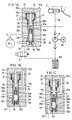
- Fig. 1A is a sectional view of the first embodiment of the present invention;
- Figs. 1B and 1C are sectional views of the same showing how it operates while the antilock control is in action;
- Fig. 2A is a sectional view of the second embodiment;
- Figs. 2B and 2C are sectional views of the same showing how it operates;
- Fig. 3 is a sectional view of the third embodiment;
- Fig. 4A is a sectional view of a prior art control valve; and
- Figs. 4B and 4C are sectional views of the same showing how it operates.
- Figs. 1A to 1C show a
flow control valve 103 in the first embodiment, which provides an improvement from the flow control valve shown in Figs. 4A to 4C. Thus like parts are represented by like numerals. - In Fig. 1A, only one of the four lines for the four wheels of a motor vehicle is shown for a convenience sake. The fluid pressure cotrol system itself is identical to the conventional one. The braking pressure PB generated in a
master cylinder 2 by tredding thebrake pedal 1 is applied to awheel brake 4 through theflow control valve 3. When reducing the braking pressure, asolenoid valve 5 is opened to discharge the pressure oil acting on thewheel brake 4 through adischarge port 31c formed in theflow control valve 3 back into apressure source 6 comprising apump 61, amotor 62 and areservoir 63. - The
flow control valve 103 comprises ahousing 31 having its interior stepped to form a large-diameter chamber and a small-diameter chamber, aspool 32 slidably mounted in the small-diameter chamber, and apiston 10 having a small-diameter portion and a large-diameter portion. The small-diameter portion is fitted in the small-diameter chamber so as to abut the front end of thespool 32 with respect to the direction in which thespool 32 is biased by aspring 34. The large-diameter portion is fitted in the large-diameter chamber orpiston chamber 12. Thepiston 10 is biased by aspring 11 in a direction away from thespool 32. Thespring 11 serves to keep thepiston 10 in the position shown in Fig. 1A in a non-braking condition. Upon application of the brake, thepiston 10 is adapted to move downwardly by the distance L owing to the pressure difference at both ends thereof produced as a result of braking, thus forcibly pushing thespool 32 downwardly toward apressure reduction chamber 36 by the distance L. When the brake is released in this state, thepiston 10 as well as thespool 32 will return to their original positions, biased by therespective springs - The chambers defined at both end faces or pressure-receiving surfaces of the
piston 10 communicate with each other through apassage 10a formed in thepiston 10, so that thepiston 10 normally receives the same fluid pressure at its small-diameter and large-diameter ends. In order to move thespool 32 without fail even during the non-antilock control, the difference in area between the pressure-receiving surfaces at both ends of thepiston 10 should be determined so that the piston will begin to move against the biasing force of thespring 11 even when the braking pressure PB is relatively small. - The stroke L of the piston is determined so that when the
piston 10 has moved downwardly by the distance L, the positional relationship between the ports formed in thespool 32 and the ports formed in the housing will be the same as shown in Fig. 4A. Therefore the stroke L1 of thespool 32 is expressed as
- Figs. 1B and 1C show the relative positions of ports which correspond to those shown in Figs. 4B and 4C, respectively. Upon appllication of the brake, the
piston 10 will push thespool 32 to move it by the distance L from the position shown in Fig. 1A. Thereafter, the valve in this embodiment operates in the same manner as with the valve shown in Figs. 4A to 4C. - Figs. 2A to 2C show the second embodiment in which the
solenoid valve 5 is integral with aflow control valve 203 and the discharge channel is opened and closed at a portion between thepressure reduction chamber 36 and thedischarge port 31c. For ease of manufacture, in thehousing 31 is mounted asleeve 37 formed with aport 37a communicating with theinlet 31a andports outlet 31b. In thesleeve 37 is slidably mounted aspool 32 formed with ports P1 and P2 adapted to bring theports input chamber 35 and a port P3 adapted to bring theoutlet 31b into communication with thepressure reduction chamber 36 through theport 37c. - A
piston 20 is mounted in apiston chamber 22 formed in front of thesleeve 37 with its small-diameter end fitted in thesleeve 37 so as to abut the front end of thespool 32. Aspring 21 is also mounted in thepiston chamber 22 to urge thepiston 20 toward thespool 32 with a larger biasing force than thespring 34. Thespring 21 mounted in a space kept at atmospheric pressure serves to hold thespool 32 in the position shown in Fig. 2A while the brake is not applied. - Upon application of the brake, the pressure oil will flow into the
input chamber 35 to move thepiston 20 in such a direction as to compress thespring 21. Thespool 32 will move together with thepiston 20 in the same direction by the same distance L by the biasing force of thespring 34. The stroke L of the piston should be shorter than the maximum stroke L4 between the upper edge of the port P2 and the lower edge of theport 37b in order to keep theinlet 31a and theoutlet 31b in communication with each other even while the antilock control is out of action. - Upon application of the brake, the
piston 20 and thespool 32 will move upwardly by the distance L from the position shown in Fig. 2A to form a large-flow channel extending from theinlet 31a to theoutlet 31b throughport 37a, port P1,input chamber 35, port P2 andport 37b. When thesolenoid valve 5 is energized and opened to start the antilock control, hydraulic oil in thepressure reduction chamber 36 will be discharged through thedischarge port 31c, creating a pressure difference across anorifice 33 between theinput chamber 35 and thepressure reduction chamber 36. Thus thespool 32 will move downwardly to shut off the large-flow channel with theedge 32b when the spool is in the position shown in Fig. 2B. When thespool 32 further moves down until theedge 32c is opened, a pressure reduction channel will be opened which extends from theoutlet 31b throughport 37c, port P3 andpressure reduction chamber 36 to thedischarge port 31c, thus reducing the fluid pressure on the wheel brake. - The
solenoid valve 5 will be deenergized to be closed when a command is given to increase the brake pressure again during the antilock control. The flow of hydraulic oil toward thedischarge port 31c will be interrupted, whereas as shown in Fig. 2C a restricted-flow channel will be formed which extends from theinlet 31a to theoutlet 31b throughport 37a, a variable-size orifice formed by theport 37a and themetering edge 32d, port P1,input chamber 35,orifice 33,pressure reduction chamber 36, port P3 andport 37c. - The opening of the variable-size orifice is automatically adjusted so that the flow rate through the restricted-flow channel is kept constant irrespective of the difference between the pressure at the
inlet 31a and that at theoutlet 31b. As with the prior art shown in Figs. 4A - 4C, the flow rate is determined by the pressure difference at both ends of theorifice 33 which is in turn determined by the biasing force of thespring 34 and the effective sectional area of thespool 32. In this arrangement, since the variable-size orifice is located upstream of theorifice 33, thesleeve 37 can be directly connected at its open end to thesolenoid valve 5. With this arrangement the valve can be positioned vertically, so that the air in the pressure reduction chamber can be expelled easily. - In the third embodiment shown in Fig. 3, a
flow control valve 303 is provided with asleeve 37 axially slidably mounted in thehousing 31 and biased by a spring 23 toward thepressure reduction chamber 36. Thesleeve 37 has its pressure-receiving surface at the side of thepressure reduction chamber 36 larger in area than that at the side of theinput chamber 35. While thepressure reduction chamber 36 is out of communication with the discharge port, the pressures in theinput chamber 35 and thepressure reduction chamber 36 will be kept equal owing to the fluid flow through theorifice 33. With this control valve, when the fluid pressure from the pressure source is introduced into thespool 32, thesleeve 37 will move upwardly by the distance L while compressing the spring 23 owing to the pressure difference at both ends thereof. The relation between the strokes L and L4 is expressed as L < L4. Otherwise this embodiment is the same in construction as the second embodiment. - The
orifice 33 shown in Fig. 2A and Fig. 3 is formed in ashim 38 urged by thespring 34 against a shoulder formed on the inner periphery of thespool 32. Theshim 38 is adapted to move toward thepressure reduction chamber 36 against the biasing force of thespring 34 when the difference between the pressure in thepressure reduction chamber 36 and the pressure in theinput chamber 35 becomes abnormally large. With this arrangement, though it is not essential to the present invention, if theorifice 33 should get clogged with foreign matter and the fluid flow from theinput chamber 35 to the pressure reduction chamber is interrupted, theshim 38 will move toward thepressure reduction chamber 36 owing to the excessively large pressure difference, forming a bypass between the outer periphery of theshim 38 and a large-diameter edge 32e of thespool 32 to connect theinput chamber 35 with thepressure reduction chamber 36. This will further improve the reliablility of the flow control valve according to the present invention. - In Figs. 2B and 2C, a different shim than the one shown in Fig. 2A is shown. But, the function is substantially the same. Thus, they are treated as the same one embodiment.
- In the preferred embodiments, the
pressure reduction chamber 36 is opened and closed by use of thesolenoid valve 5. But the flow control valve according to the present invention may be applied to a well-known mechanical antilock device in which thepressure reduction chamber 36 is opened and closed with a damping valve controlled by a sensor for sensing an angular velocity of the wheels.
Claims (5)
- A flow control valve for use in an antilock control device, comprising a housing (31) having an inlet port (31a) communicating with a pressure source (6) and an outlet port (31b) communicating with a wheel brake (4), a spool (32) axially slidably mounted in said housing and formed with a fluid channel including an orifice (33), and a first biassing means (34) for biassing said spool in one direction, said spool (32) being adapted to form a large-flow passage connecting said inlet port and said outlet port together when it is in a first position and to form a restricted-flow passage extending from said inlet port to said outlet port through said orifice when it is in a second position, characterized by a slide means (10,20) mounted in said housing and arranged in such a position as to receive the braking fluid pressure generated in said pressure source on at least one of both ends thereof, and a second biassing means (11,21) for biassing said slide means (10,20) on the other end thereof, said slide means being adapted to slide axially against the biassing force of said second biassing means each time the brake is applied, said spool (32) abutting said slide means (10,20) with the biassing force of the first biassing means (34) when said slide means slides axially relative to said housing (31) against the biassing force of said second biassing (11,21) means.
- A flow control valve for use in an antilock control device, comprising a housing (31) having an inlet port (31a) communicating with a pressure source and an outlet port (31b) communicating with a wheel brake, a spool (32) axially slidably mounted in said housing (31) and formed with a fluid channel including an orifice (33), and a first biassing means (34) for biassing said spool (32) in one direction, said spool being adapted to form a large-flow passage connecting said inlet (31a) port and said outlet port (31b) together when it is in a first position and to form a restricted-flow passage extending from said inlet port to said outlet port through said orifice when it is in a second position, characterized by a slide means (37) mounted in said housing and arranged in such a position as to receive the braking fluid pressure generated in said pressure source on at least one of both ends thereof, and a second biassing means (23) for biassing said slide means on the other end thereof, said slide means being adapted to slide axially against the biassing force of said second biassing means (23) each time the brake is applied, said spool (32) abutting said housing with the biassing force of said first biassing means (34) when said slide means slides axially relative to said housing against the biassing force of said second biassing means (23).
- A flow control valve as claimed in claim 1, wherein said slide means is a piston (10) adapted to abut said spool (32) on its end opposite to the end on which the biassing force of said first biassing means (34) acts.
- A flow control valve as claimed in claim 1, further comprising a sleeve (37) fixedly mounted in said housing so that said spool (32) and said piston (20) are adapted to move relative to said sleeve.
- A flow control valve as claimed in claim 2, wherein said slide means is a sleeve (37) mounted between the inner peripheral surface of said housing (31) and the outer peripheral surface of said spool (32) so as to be slidable relative to said housing and said spool.
Applications Claiming Priority (2)
| Application Number | Priority Date | Filing Date | Title |
|---|---|---|---|
| JP63239420A JPH0288350A (en) | 1988-09-24 | 1988-09-24 | Flow control valve for antilock |
| JP239420/88 | 1988-09-24 |
Publications (3)
| Publication Number | Publication Date |
|---|---|
| EP0361336A2 EP0361336A2 (en) | 1990-04-04 |
| EP0361336A3 EP0361336A3 (en) | 1990-11-28 |
| EP0361336B1 true EP0361336B1 (en) | 1994-07-20 |
Family
ID=17044508
Family Applications (1)
| Application Number | Title | Priority Date | Filing Date |
|---|---|---|---|
| EP89117594A Expired - Lifetime EP0361336B1 (en) | 1988-09-24 | 1989-09-22 | Flow control valve for antilock brake control device |
Country Status (5)
| Country | Link |
|---|---|
| US (1) | US5026123A (en) |
| EP (1) | EP0361336B1 (en) |
| JP (1) | JPH0288350A (en) |
| KR (1) | KR920004577B1 (en) |
| DE (1) | DE68916892T2 (en) |
Families Citing this family (21)
| Publication number | Priority date | Publication date | Assignee | Title |
|---|---|---|---|---|
| DE59003631D1 (en) * | 1989-06-17 | 1994-01-05 | Teves Gmbh Alfred | BLOCK-PROTECTED, HYDRAULIC BRAKE SYSTEM. |
| DE4015745A1 (en) * | 1989-10-06 | 1991-04-18 | Teves Gmbh Alfred | BLOCK-PROTECTED, HYDRAULIC BRAKE SYSTEM |
| DE4016746A1 (en) * | 1990-05-25 | 1991-11-28 | Teves Gmbh Alfred | BRAKE PRESSURE CONTROL DEVICE |
| DE4016752A1 (en) * | 1990-05-25 | 1991-11-28 | Teves Gmbh Alfred | BRAKE PRESSURE CONTROL DEVICE AND METHOD FOR USE THEREOF |
| JP3111461B2 (en) * | 1990-07-03 | 2000-11-20 | 株式会社デンソー | Vehicle brake pressure control device |
| US5445447A (en) * | 1990-09-28 | 1995-08-29 | Lucas Industries Public Limited Company | Hydraulic anti-locking systems for vehicles |
| DE69124253T2 (en) * | 1990-09-28 | 1997-04-30 | Lucas Ind Plc | HYDRAULIC ANTI-BLOCKING BRAKE SYSTEMS FOR VEHICLES |
| JPH05502839A (en) * | 1990-11-16 | 1993-05-20 | アルフレッド・テヴェス・ゲーエムベーハー | brake pressure control device |
| DE4134427A1 (en) * | 1991-10-18 | 1993-04-22 | Teves Gmbh Alfred | BLOCK-PROTECTED HYDRAULIC BRAKE SYSTEM |
| US5356210A (en) * | 1991-03-16 | 1994-10-18 | Alfred Teves Gmbh | Anti-lock hydraulic brake system |
| DE4134490A1 (en) * | 1991-10-18 | 1993-04-22 | Teves Gmbh Alfred | BLOCK-PROTECTED HYDRAULIC BRAKE SYSTEM |
| GB9211852D0 (en) * | 1992-06-04 | 1992-07-15 | Lucas Ind Plc | Improvements in solenoid-operated fluid-flow control valves |
| JPH06127361A (en) * | 1992-10-14 | 1994-05-10 | Tokico Ltd | Brake fluid pressure control device |
| US5330259A (en) * | 1992-12-22 | 1994-07-19 | Alliedsignal Inc. | Electrohydraulic braking system with remote booster |
| JP3536444B2 (en) * | 1995-07-10 | 2004-06-07 | トヨタ自動車株式会社 | Hydraulic brake device |
| US5681098A (en) * | 1995-08-29 | 1997-10-28 | Kelsey Hayes | Anti-locking brake system with a switchable orifice control valve |
| US5725288A (en) * | 1995-10-27 | 1998-03-10 | Kelsey-Hayes Company | Isolation valve for an antilock brake system having a controlled bypass |
| US6199823B1 (en) | 1999-09-17 | 2001-03-13 | Tlx Technologies | Solenoid valve with an external sleeve armature |
| JP2005047469A (en) * | 2003-07-31 | 2005-02-24 | Advics:Kk | Brake device |
| US8936322B2 (en) * | 2010-04-20 | 2015-01-20 | Robert Bosch Gmbh | Brake system with selector valve for selecting between two modes of operation |
| CN111923883B (en) * | 2020-07-15 | 2022-11-11 | 中国第一汽车股份有限公司 | Brake system matching analysis method and system considering active braking function |
Family Cites Families (6)
| Publication number | Priority date | Publication date | Assignee | Title |
|---|---|---|---|---|
| US3157052A (en) * | 1961-07-03 | 1964-11-17 | Ford Motor Co | Anti-skid brake system |
| JPS5421912B2 (en) * | 1971-12-02 | 1979-08-02 | ||
| JPS5240927B2 (en) * | 1972-07-04 | 1977-10-15 | ||
| US4436348A (en) * | 1981-10-13 | 1984-03-13 | Lucas Industries Public Limited Company | Anti-skid hydraulic braking systems for vehicles |
| GB8512610D0 (en) * | 1985-05-18 | 1985-06-19 | Lucas Ind Plc | Hydraulic anti-skid braking systems |
| US4637662A (en) * | 1985-10-18 | 1987-01-20 | Allied Corporation | Anti-locking modulating valve for displacement type full power master cylinder |
-
1988
- 1988-09-24 JP JP63239420A patent/JPH0288350A/en active Pending
-
1989
- 1989-09-21 US US07/410,587 patent/US5026123A/en not_active Expired - Fee Related
- 1989-09-22 DE DE68916892T patent/DE68916892T2/en not_active Expired - Fee Related
- 1989-09-22 EP EP89117594A patent/EP0361336B1/en not_active Expired - Lifetime
- 1989-09-23 KR KR1019890013725A patent/KR920004577B1/en not_active IP Right Cessation
Also Published As
| Publication number | Publication date |
|---|---|
| EP0361336A2 (en) | 1990-04-04 |
| KR920004577B1 (en) | 1992-06-11 |
| EP0361336A3 (en) | 1990-11-28 |
| US5026123A (en) | 1991-06-25 |
| KR900004543A (en) | 1990-04-12 |
| JPH0288350A (en) | 1990-03-28 |
| DE68916892D1 (en) | 1994-08-25 |
| DE68916892T2 (en) | 1995-03-02 |
Similar Documents
| Publication | Publication Date | Title |
|---|---|---|
| EP0361336B1 (en) | Flow control valve for antilock brake control device | |
| SU1484290A3 (en) | Hydraulic antiskid brake system for vehicles | |
| US5605386A (en) | Solenoid valve for slip-controlled hydraulic brake systems in motor vehicles | |
| EP0363845B1 (en) | Flow control valve for antilock brake control device | |
| US5002344A (en) | Fluid pressure controller for antilock brake control device | |
| US4685749A (en) | Hydraulic pressure control device for use in vehicle anti-skid braking system | |
| US4474413A (en) | Hydraulic anti-skid braking systems for vehicles | |
| GB2090929A (en) | Anti-skid hydraulic braking systems for vehicles | |
| US4750789A (en) | Vehicular hydraulic brake system with anti-locking | |
| JPS60255562A (en) | Hydraulic brake system | |
| EP0875431A2 (en) | Flow control valve | |
| EP0242132B1 (en) | Improvements in hydraulic anti-skid braking systems for vehicles | |
| JPH09502944A (en) | Hydraulic brake system with slip control | |
| US4129341A (en) | Modulator valve assembly for a fluid braking system | |
| EP0171901B1 (en) | Anti-skid hydraulic braking systems for vehicles | |
| US4077673A (en) | Fluid pressure controlling device | |
| US5678902A (en) | Hydraulic anti-locking braking systems for vehicles | |
| US5741049A (en) | Brake proportioning valve | |
| US4636008A (en) | Anti-skid braking control system | |
| US4017126A (en) | Vehicle anti-skid braking device | |
| US5098173A (en) | Anti-locking hydraulic brake system | |
| US5626403A (en) | Brake pressure regulator | |
| US3937127A (en) | Hydraulic brake booster with shut-off means | |
| US5310253A (en) | Braking pressure control device | |
| EP0507492B1 (en) | Improvement in hydraulic anti-lock braking systems for vehicles |
Legal Events
| Date | Code | Title | Description |
|---|---|---|---|
| PUAI | Public reference made under article 153(3) epc to a published international application that has entered the european phase |
Free format text: ORIGINAL CODE: 0009012 |
|
| AK | Designated contracting states |
Kind code of ref document: A2 Designated state(s): DE GB |
|
| PUAL | Search report despatched |
Free format text: ORIGINAL CODE: 0009013 |
|
| AK | Designated contracting states |
Kind code of ref document: A3 Designated state(s): DE GB |
|
| 17P | Request for examination filed |
Effective date: 19901128 |
|
| 17Q | First examination report despatched |
Effective date: 19920210 |
|
| GRAA | (expected) grant |
Free format text: ORIGINAL CODE: 0009210 |
|
| AK | Designated contracting states |
Kind code of ref document: B1 Designated state(s): DE GB |
|
| REF | Corresponds to: |
Ref document number: 68916892 Country of ref document: DE Date of ref document: 19940825 |
|
| PLBE | No opposition filed within time limit |
Free format text: ORIGINAL CODE: 0009261 |
|
| STAA | Information on the status of an ep patent application or granted ep patent |
Free format text: STATUS: NO OPPOSITION FILED WITHIN TIME LIMIT |
|
| 26N | No opposition filed | ||
| REG | Reference to a national code |
Ref country code: GB Ref legal event code: 746 Effective date: 19951115 |
|
| PGFP | Annual fee paid to national office [announced via postgrant information from national office to epo] |
Ref country code: GB Payment date: 19970915 Year of fee payment: 9 |
|
| PGFP | Annual fee paid to national office [announced via postgrant information from national office to epo] |
Ref country code: DE Payment date: 19970926 Year of fee payment: 9 |
|
| PG25 | Lapsed in a contracting state [announced via postgrant information from national office to epo] |
Ref country code: GB Free format text: LAPSE BECAUSE OF NON-PAYMENT OF DUE FEES Effective date: 19980922 |
|
| GBPC | Gb: european patent ceased through non-payment of renewal fee |
Effective date: 19980922 |
|
| PG25 | Lapsed in a contracting state [announced via postgrant information from national office to epo] |
Ref country code: DE Free format text: LAPSE BECAUSE OF NON-PAYMENT OF DUE FEES Effective date: 19990701 |