EP0360764A2 - Apparatus able for converting a rotary motion into a rectilinear motion for the advancement of a self-propelled vehicle - Google Patents
Apparatus able for converting a rotary motion into a rectilinear motion for the advancement of a self-propelled vehicle Download PDFInfo
- Publication number
- EP0360764A2 EP0360764A2 EP89830397A EP89830397A EP0360764A2 EP 0360764 A2 EP0360764 A2 EP 0360764A2 EP 89830397 A EP89830397 A EP 89830397A EP 89830397 A EP89830397 A EP 89830397A EP 0360764 A2 EP0360764 A2 EP 0360764A2
- Authority
- EP
- European Patent Office
- Prior art keywords
- mass
- piston
- cylinder
- retracted position
- solid
- Prior art date
- Legal status (The legal status is an assumption and is not a legal conclusion. Google has not performed a legal analysis and makes no representation as to the accuracy of the status listed.)
- Granted
Links
Images


Classifications
-
- F—MECHANICAL ENGINEERING; LIGHTING; HEATING; WEAPONS; BLASTING
- F16—ENGINEERING ELEMENTS AND UNITS; GENERAL MEASURES FOR PRODUCING AND MAINTAINING EFFECTIVE FUNCTIONING OF MACHINES OR INSTALLATIONS; THERMAL INSULATION IN GENERAL
- F16H—GEARING
- F16H33/00—Gearings based on repeated accumulation and delivery of energy
- F16H33/20—Gearings based on repeated accumulation and delivery of energy for interconversion, based essentially on inertia, of rotary motion and reciprocating or oscillating motion
-
- F—MECHANICAL ENGINEERING; LIGHTING; HEATING; WEAPONS; BLASTING
- F03—MACHINES OR ENGINES FOR LIQUIDS; WIND, SPRING, OR WEIGHT MOTORS; PRODUCING MECHANICAL POWER OR A REACTIVE PROPULSIVE THRUST, NOT OTHERWISE PROVIDED FOR
- F03G—SPRING, WEIGHT, INERTIA OR LIKE MOTORS; MECHANICAL-POWER PRODUCING DEVICES OR MECHANISMS, NOT OTHERWISE PROVIDED FOR OR USING ENERGY SOURCES NOT OTHERWISE PROVIDED FOR
- F03G3/00—Other motors, e.g. gravity or inertia motors
-
- F—MECHANICAL ENGINEERING; LIGHTING; HEATING; WEAPONS; BLASTING
- F02—COMBUSTION ENGINES; HOT-GAS OR COMBUSTION-PRODUCT ENGINE PLANTS
- F02B—INTERNAL-COMBUSTION PISTON ENGINES; COMBUSTION ENGINES IN GENERAL
- F02B75/00—Other engines
- F02B75/02—Engines characterised by their cycles, e.g. six-stroke
- F02B2075/022—Engines characterised by their cycles, e.g. six-stroke having less than six strokes per cycle
- F02B2075/025—Engines characterised by their cycles, e.g. six-stroke having less than six strokes per cycle two
Abstract
Description
- The invention refers to an apparatus for transforming a rotary motion into a rectilinear motion.
- Substantially the propulsion apparatus of the invention is characterized in that it comprises, on a housing unidirectionally movable in a direction corresponding to an axis thereof: a sliding mass designed to take up a position of maximum distance and a retracted position along an axis parallel to said axis of the housing; an auxiliary motor which causes the mass to cyclically take up said position of maximum distance; and means for causing the sudden return of the mass from said position of maximum distance to the retracted position; the momentum and consequently the impulse acquired by said mass during the return phase are equal to those acquired during said phase by the housing, which accordingly moves repeatedly forward by a given length with a unidirectional movement during each forward and backward movement of said mass.
- In a possible embodiment of the invention said apparatus comprises in combination: a housing movable on a carriage or other means able to move unidirectionally in a direction corresponding to an axis of the housing; on the housing a motor (endothermal, or electrical or other type), able to drive into rotation, about an axis orthogonal to said axis of the housing, a platform with a fixture and a mass comprising guide means for the sliding of the mass along an axis orthogonal to the axis of rotation, so that the mass is predisposed to take up a retracted position - that is, a position close to said axis of rotation - and a position of maximum distance from said axis and thus of maximum centrifugal force, in which it is endowed with the maximum momentum; as well as means for determining, over a suitable angular position, the sudden return of said mass from the position of maximum distance to the retracted position, and means to keep it in retracted position over a certain angular displacement of the fixture and then release it for allowing it, by centrifugal force, to move away until it reaches again said position of maximum centrifugal force; owing to the action of the said return means, the momentum of the centrifugal mass, when it reaches the position of maximum distance, being transferred, on the instant of and following the return, to said housing which, for each revolution of the fixture, receives a thrust in the direction of said, axis which causes the displacement thereof in the direction of the carriage advancement.
- In a possible embodiment of the invention, there is provided that the means for the sudden return of the mass be made up of a cylinder-piston system of an internal combustion engine without crank mechanism, fixed to and rotating solid with said fixture and whose piston is connected rigidly with the mass to slide solid therewith, so that the travel of the mass from the retracted position to the position of maximum distance correspond to the compression phase of the cylinder-piston system and the ignition of the mixture for propelling the motor, while the combustion and expansion phase of said system causes the sudden return of the mass from the position of maximum distance to the retracted position; means are also provided, solid with the fixture, for the admission of the fuel and of the combustion air inside the cylinder and for causing the ignition of the corresponding mixture approximately in the above mentioned position of maximum distance of the mass.
- The propulsion apparatus may comprise a cylinder-piston system of an internal combustion engine operating according to a two-stroke cycle, whose piston is rigidly connected with the mass in order to slide solid therewith - so that the travel of the mass from the retracted position to the forward position corresponds to the compression phase of the cylinder-piston system and to the ignition of an engine propelling mixture, while the combustion and expansion phase of said system causes the sudden return of the mass from the forward position to the retracted position - and whose crank mechanism does not transmit rotary energy during said expansion owing to the presence of a unidirectional, that is, free wheel, mechanism on the crank shaft; an auxiliary motor (endothermal, electrical or of other type) which, through a drive and said free wheel device, acts on said crank mechanism to cause the piston to run the compression stroke and the mass to run the moving away travel at a speed considerably lower than that of the return travel; the momentum and thus the impulse acquired by said mass on the return phase at the high expansion speed of the piston, being equal to that of the mass of the housing, which, therefore, at each cycle of said cylinder-piston system, moves repeatedly forward by a given length, a uniderectional motion thus taking place with a speed which is higher the greater the number of cycles of the cylinder-piston system per unit time.
- Further advantageous features of the invention are set out in the dependent claims.
- The invention will be better understood by following the description and the attached drawing, which shows a practical, non limiting example of the same invention. In the drawing:
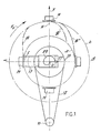
- Fig. 1 shows in a very schematic way the device according to the invention;
- Fig. 2A shows schematically a carriage being restrained for unidirectionally sliding on a plane on which said device is supported;
- Figs. 2B and 2C in a very schematic way show, the first the restraint forms of the carriage and the second how it is possible to compare the device with a common traction system with wheels rotated by a driving torque;
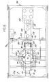
- Fig. 3 shows schematically, but in greater details, a top view of the apparatus making up the device according to the invention, in the position wherein the centrifugal mass is at its maximum distance position and is about to be moved back;
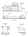
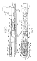
- Figs. 4, 5 and 6 show schematically a sectional view according to a vertical plane passing through the axis of the piston, a sectional view according to line V-V of Fig. 4 and an ensemble plan view of the propulsion unit, respectively, according to the invention;
- Fig. 7 shows an enlarged, partial, plan view, with cutaway parts, of the rotating fixture of the propulsion unit;
- Fig. 8 shows, in a view similar to Fig. 7, the movements of the centrifugal mass of the unit, the cylinder-piston system and its auxiliary members being omitted for the sake of clarity;
- Figs. 9A, 9B, 9C and 9D show schematically working phases of the unit;
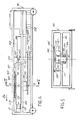
- Fig. 10 shows schematically a plan view, partly in section, of a propulsion apparatus according to a further embodiment; and
- Fig. 11 shows schematically a side view thereof.
- Fig. 1 shows a mass M, which is fixed on the top of
columns 17 of a rotating fixture to be described later. Said fixture rotates with uniform motion about an axis O and the mass M travels initially the lower half (Fig. 1) of the circumference of minor diameter designated by a. When the mass M, by rotating in clockwise direction, arrives at L, by centrifugal force, i.e. centrifugal reaction, and being left free to slide radially as it is no longer retained by certain members, it passes from L (on the small circumference) to N (on circumference b of greater diameter) by following a curve g; since, in this way, it increases its distance from the axis of rotation, the centrifugal force Fc (Fig. 2A) to which the mass M is subjected increases as well. Since the travel of the mass M from the retracted position corresponding to the circumference a to the position of maximum distance corresponding to the circumference b is limited by limit stops (better described later on) fixed at the innermost end ofcolumns 17, the force exerted by the mass M on thecolumns 17 and by these on the fixture - which is made to rotate on a structure solid with the carriage illustrated in Fig. 2A - causes an exchange of momentum between the mass M (whose movement in radial direction comes to a stop) and the structure which tends to move forward in the direction of arrow F. The mass M at position N is still subjected to an intense centrifugal force Fc and, by continuing its rotation, it is forcely brought back, by mechanical means - such as a fixed cam or eccentric 29 - or of thermal means, fluid-operated means or of any other nature, onto the circumference α. In connection with the fact that this return may be more or less sudden, the mass M may run different curves, like those indicated by g′ and g˝ respectively. The thus re-entered mass M results therefore forced to travel the circunference a, of minor diameter, along the whole lower semi-circunference from β to α opposite to position N. The withdrawal from circumference a as far as to circumference b and the return from b to a of mass M take place instead along the semi-circumference from α to β. - Fig. 2A shows the effects of the return of mass M up to the retracted position. A carriage Q supported on wheels in contact with a horizontal plane carries the mass M which is at position N and is about to be called back (by means, as it will be explained later, of the eccentric 29). Being driven into rotation, the mass M is subjected to a centrifugal force Fc, so that, in order to recall the mass towards the rotation axis O-O a force T shall be applied thereto (which will act, for example, on the roller or tappet 27 in contact with the fixed cam 29), which force T shall be greater than Fc. But to the force T will correspond an equal and opposite reaction RT which (for example through the fixed cam 29) will act on the structure of the carriage Q. If R indicates the total resistance to the advancement of carriage Q, with the apparatus in question mounted thereon, the carriage will move forward according to arrow F when the reaction RT, for a given rotational speed of the fixture carrying the mass M, will result greater than the total resistance R to the advancement of carriage Q. The phenomenon is repetitive, so that once RT has become greater than R, at each revolution of the mass M the carriage will be subjected to a thrust RT that will move it forward.
- It is useful to point out that in the case of a vehicle whose advancement is due to driving wheels, it is necessary that the peripheric force T, almost tangent to the tire and applied by the driving wheel to the road surface, exceeds the portion of total resistance to the advancement of the vehicle which is considered to be applied to the concerned wheel to which the half-axle transmits a torque Mt = T - r, where r indicates the radius of the wheel (Fig. 2C).
- The rotation of the mass M is obtained through an independent motor (electrical or other type) installed on the carriage Q and which, through a
pulley 11 and a drive, will rotate the fixture in clockwise direction, according to arrow FE, with respect to which thecolumns 17, to which the base of mass M is fixed, are able to slide. Following the rotation of said motor in clockwise direction (in the example of the drawing), the carriage Q will be subjected to a torque equal and opposite to that of the motor, that is, in the direction of arrow FQ (Fig. 2B) and this torque will be balanced by restraint forces H, acting on the carriage wheels, caused by the friction thereof with the contact plane, due also to the considerable carriage load weighing on the structure. Persisting, however, a trend of the carriage to rotate, two centrifugal masses may be provided, like that indicated by M, driven into opposite directions one to the other by two separate motors or by a single motor with two drives; in this case, the internal forces of the structure shall support the two opposite torques, but any trend to rotate the carriage will be eliminated. - Incidentally, the concerned centrifugal mass or masses may be rotated - together with their fixture and devices - also on a plane perpendicular to the carriage plane, which has been supposed horizontal, the described mechanical phenomena remaining unchanged.
- For a detailed description of the apparatus reference is now made to Fig. 3, in which the mass is at position of the maximum distance, i.e., at N (Fig. 1), and is about to be moved back. The apparatus according to the invention comprises a housing S, provided with
wheels 3, for the support and guide on a plane which, as stated earlier in this description, is supposed to be horizontal. Thewheels 3 engage the housing so that this can move unidirectionally according to arrow F, that is parallel to the middle longitudinal plane of the same housing. The housing S may be assimilated to a carriage having longitudinal development, comprising a horizontal plane above which afixture 5, formed as an U-shaped bracket whoselegs 7 are connected to each other at their ends by a crosspiece 9 is made to rotate in the direction of arrow F5 about an axis orthogonal to said plane. The rotation axis of thefixture 5 is represented by its trace axis O (in the example of the drawing) and such rotation is obtained through abelt drive fixture 5 the motion of a motor P (electrical, endothermic, or of any other type). Between the motor P and drive 11, 12, 13 a variator may be interposed for selecting the rotation offixture 5. Thefixture 5 is supported by an underlying platform (not shown) driven into rotation by a shaft supported by the plane of thehousing 5 and solid to the wheel 13. - In the vicinity of the central part of the U-shaped
fixture 5 two pairs ofside guides 15 are secured to thelegs 7 for the slide of two pairs ofrods 17 in the direction parallel to the longitudinal axis of symmetry of the fixture. The ends of therods 17 are secured bynuts 19 to aplate 21 on which there is fixed a centrifugal mass M (of parallelepiped form in the example of the drawing). The opposite ends of therods 17 are fixed bybolts 23 to anotherplate 25 and the length of therods 17 is such that the mass M may take up both the retracted position by travelling along the circumference a (Fig. 1) and the position of maximum distance from the axis of rotation by travelling along the circumference b. Following the rotation offixture 5, a modest centrifugal force acts upon the mass M in the "retracted" position, while such centrifugal force becomes significantly high at the said position of maximum distance; upon reaching this position, the mass M, after its radial displacement guided by therods 17 slidingly movable within theguides 15 has, of course, a high momentum. Once reached this position - in which is held by the rods 17 - the mass M would remain permanently in said position if it were not for the return means 27, 29 which bring it back, at each revolution offixture 5, to the retracted position. Numeral 27 indicates a roller tappet disposed for following the eccentric orcam profile 29. The eccentric 29 does not rotate, as it is fixed to a portion (not shown) of the housing S, which is above thefixture 5 and is so structured and connected as to support, without deformations, the high forces which it can receive from thetappet 27. Thetappet 27 may rotate idly about a shaft cantiliverly projecting orthogonal to a T-shaped skid (in the example of the drawing), which can slide within side guides (not shown) formed on thelegs 7 of thefixture 5; when thetappet 27 is pushed outwardly by the eccentric 29, it tends "to overturn" theskid 31 and this overturning is prevented by the rolling bearings which slide within said side guides on which they discharge said overturning torque. - The
eccentric profile 29 is crucial as far as the operation of the apparatus is concerned; it comprises an almost rectlinear portion AB, with which thetappet 27 remains in contact when the mass M moves from the retracted position to the position of maximum distance. The portion AB is followed by a portion BC, with a shape heavily inclined with respect to the preceding one, which causes the return - which must be sudden, i.e., abrupt - of the mass M to the retracted position. The length BC is joined at D by a wide length EF, shaped like a circle arc, along which thetappet 27 keeps the mass M in retracted position; from the length EF, a very short junction FA leads to the length AB, since for the operation of the apparatus, it is very important that the "output" of the mass M takes place abruptly, and that the return occurs enough abruptly as well. - The fixed eccentric 29 is so oriented that the return of mass M is completed when the
fixture 5 has its own longitudinal axis parallel to the direction of advancement of the housing S, after a rotation of 180°. By such return, the momentum owned by the mass M upon its reaching the position of maximum distance, is partially or mostly transferred, through the return means 29, 27, to the housing S which, at each revolution of thefixture 5, receives a thrust in the direction of said axis - and thus of the arrow F - which causes its displacement in the direction of the carriage advancement. In this way, the rotary motion imparted to thefixture 5 by the motor P - which the housing 1 is supplied with - is transformed, by the apparatus according to the invention, into a rectilinear motion of the same housing according to arrow F. - The
skid 31 is connected to theplate 25, so as to move solid therewith, but said connection is carried out through articulation means for the two parts. This is necessary for allowing theskid 31 to have some degree of freedom of movements relative to theplate 25 which, being rigidly connected to therods 17, could not follow such movements (due to the forces transmitted by the tappet 27), although they are of little magnitude. - The
skid 31 is in turn connected to arod 37 sliding within ahole 39 of the crosspiece 9, which rod projects beyond said crosspiece and is solid to acup member 41 able to compress acompression spring 43. The coils of thespring 43 develop around theextension 47, of reduced trasverse dimensions, of therod 37 past thecup 41, and said spring reacts against thebottom wall 45 of anU-shaped bracket 49, said bottom wall having a hole for the sliding of theextension 47. When, because of the action of the eccentric 29 on theroller 27, the mass M is recalled to take up its retracted position, theskid 31 pushes therod 37 in the direction opposite to arrow F, so that thecup member 41 compresses thespring 43 against thebottom wall 45. Therefore, thespring 43 accumulates and retains some amount of elastic potential energy for all the time the mass M is in retracted position. When the mass M is launched, that is, when thetappet 27 runs the length AB of the eccentric 29, this potential energy is released in the sense that thespring 43, throughcup 41,rod 37,skid 31 andcolumns 17, imparts a thrust to the mass M. This thrust action has the purpose of causing the mass M to take up, in a very short time, a position as far away as possible from the rotation axis 0-0 of thefixture 5, so as to be immediately subjected to a centrifugal force and pushed outwardly thereby. - The above description refers to an apparatus in which the return of the mass M (or of two counter-rotating masses) is provided through a
tappet 27 which follows the profile of a fixed eccentric 29. It is clear, however, that the result of having the momentum (or portion of the momentum), of the centrifugal mass M transferred to the housing S to move it forward, may be achieved by providing return means different from the described mechanical means formed by the coupling of an eccentric 29 and atappet 27. For example, elastic means may be provided able to intervene in the sense of exerting a sudden return action on the mass M when it is in the position of maximum distance, said elastic means being possibly "loaded" during the rotation steps of thefixture 5 between a "launch" of mass M and the next. - As an alternative to said elastic means, pneumatic means may be provided (such as a compressed air operated cylinder-piston system provided for the return) or even thermal means, that is, means able to transform into a mechanical energy, for the return, the pressure energy generated by combustion (steam-operated cylinder; cylinder of an endothermal motor without crank mechanism, etc.).
- According to the example of Figs. 4 to 6, the propulsion apparatus according to the invention comprises a fixed
structure 101, movable on a carriage or other means able to advance unidirectionally with very limited friction, which has astout support framework 103. At a position on to the left (in the example of the drawing, Fig. 4) ahub 104 projects under theframework 103, said hub being provided with a pair ofsupport bearings 105 having also a thrust bearing function for the rotation of a short vertical throughshaft 107. On the lower end of the shaft 107 achain wheel 109 is keyed which, through a chain 111 and apinion 113, is driven into rotation by aspeed variator 108 which is actuated in turn, via adrive 110, by an auxiliary motor 112 (endothermal, electrical or of other type). Through theshaft 107, thechain wheel 109 drives into rotation, in the direction of arrow f115 and aboveframework 103, afixture 115 made up of an U-shaped bracket with thecentral part 119 of the U disposed on the left (in the example of the drawing), while the legs of the U are connected, on the right hand side, by acrosspiece 117. Outside thewalls 116 of thefixture 115 guides 137 are fixed inside which columns orrods 131 slide (four in the example of the drawing), on top of which a centrifugal mass M is fixed in the central part of the U. On the opposite end, therods 131 are fixed to atransverse plate 136. The centrifugal mass M, after the sliding of therods 131 may take, by moving radially, a retracted (or re-entered) position, in which it is placed at the minimum distance from the axis of rotation Y of thefixture 115, and a position of maximum distance from said axis (shown in Fig. 7), in which the mass is subjected to the maximum centrifugal force or reaction. In order to take up the re-entered position, the mass M must be recalled, at a suitable angular position, by a force greater than said centrifugal force; characteristically, according to the invention, the return of the mass M takes place by means of apiston 125 sliding within acylinder 127, the cylinder-pyston system 125-127 making up, together with ahead 129, a crankless two-stroke combustion engine. Thepiston 125, whose rear is fixed to theplate 136 through the symmetrical columns 135 (four in the example of the drawing), and which slides thereby solid with the mass M, causes the return of said mass during the expansion cycle of the engine, as will be better explained later, at each revolution of thefixture 115. The walls 127L of thecylinder 127 are fixed within the walls offixture 115 and thepiston 125 may sealingly slide inside thecylinder 127, performing a working stroke equal to the one of mass M with which it is connected as above described. - The structure 101 (Fig. 4 and 5) has a
portion 106 which overlaps thefixture 115 which thereby rotates between theportion 106 and the housing underneath it to which thehub 104 is fixed. To theportion 106 an eccentric 163 and aflat ring 165 are fixed. With the fixed eccentric 163 a roller ortappet 167 is engaged, which can rotate idly about ashaft 169 cantiliverly projecting upwards from a block or skid 130 sliding onopposite guides 132 fixed to thewalls 116 offixture 115. Within ahole 121 of crosspiece 117 arod 123 may slide in both directions of arrow f123, which rod is fixed at one end to plate 136 so as to slide solid withpiston 125 and with the mass M. Therod 123 is also connected to theskid 130 through acushioning group roller 167 and onshaft 169, behaves like a rigid connection and such it is considered in describing the operation of the propulsion unit according to the invention, during which theskid 130 may be normally considered as being solid withrod 123. - The mutual action between the eccentric 163 and the
roller 167 comes into effect to determine the position(s) of the mass M relative to the axis of rotation offixture 115, the mass resulting solid with therod 123 throughrods 131 andplate 136. The profile of the fixed eccentric 163 (Figs. 6 and 8) is so designed as to be able to retain the mass M by theroller 167, after the return to the retracted position, for about half a revolution offixture 115, that is, when the mass comes to rotate on the right hand side of Figs. 4 and 7; afterwards said profile allows the moving away of the mass as far as the position of maximum distance from the axis of rotation and, through a relatively steep length, is able to recall, i.e., to cause the mass M to return, after it has reached such position of maximum distance and of maximum centrifugal force. Since, however, in the propulsor according to the invention, the return of the mass is obtained by the stroke ofpiston 125 during the expansion cycle, the eccentric 163 must, usually, just keep the mass M in said retracted position, as already mentioned, for about half a revolution. - The
internal combustion engine injector 139 for the fuel, with aspark plug 141, with anexhaust duct 143 and a duct 145 for the admission of the scavenging air. In the expansion cycle of said engine, thepiston 125 moves away from thehead 129; on the head 123 (Fig. 7) there is fixed arack 147 which, when therod 123 moves back solid withplate 136 and thus withpiston 125, it causes, through anidle gear 149, the advancement in the direction of arrow f151 of a rod 151, also provided with a rack 152 meshing withgear 149, on one end of which rod apiston 153 is fixed; thepiston 153, together with acylinder 155, makes up a pump for pumping scavenging air during said expansion cycle inside thecylinder 127 through the inlet duct 145. The rod 151 slides within a guide hole formed on the wall 150 of astructure 156 fixed on a wall of thefixture 115; thepump non-return valve 146 is located on duct 145. The fuel reachesinjector 139 through apipe 159 which comes out from an injection pump 161 driven by a device comprising aninclined plane 158 and aroll 160; theinclined plane 158 is disposed on therod 123 at such a position as to cause the injection during the compression cycle or about at its end. The injection pump 161 sucks the fuel from a fixed reservoir for example through a rotating valve (not shown). - The ring 165 - which can be fixed to isolating blocks - has a
front contact ring 173 on which acontact wheel 183 rolls supported by a fork solid with thefixture 115, to draw the positive of a low-voltage direct current for the supply of the primary of acommon distributor coil 177 whose secondary feeds high-voltage current to theplug 141 and which is fixed to awall 116 of thefixture 115. The positive of said primary current, supplied by a battery 175 (Fig. 6), reaches, via thewheel 183, an interrupting member 179 (Fig. 7) which has the same functions as the so-called "contact breaker". The primary of the coil receives the negative through the metal mass ofstructure 101 andfixture 115; themember 179 is driven by a sensor 181 (made up of an accurate proximity detector or the like), which transmits a signal thereto - to cause the interruption of said low voltage current - the moment the mass M reaches the position of maximum distance from the axis of rotation offixture 115, on which thepiston 125 has ended the compression cycle and when, on the same time, the axis of the cylinder-piston system structure 101 with the head facing the side towards which the advancement must occur, that is, in the position shown in Fig. 7. In such position, for every cycle ofengine member 179, thecoil 177 emits a high-voltage current which, through acable 184, causes a spark between the electrodes of theplug 141 thereby determining the ignition and burning of the mixture compressed insidecylinder 127, with a strong push onhead 129 and the back movement ofpiston 125; thepiston 125 performs thus its expansion and gas exhaust stroke and causes the return of mass M to the retracted position, by transmetting a force to plate 136 greater than the centrifugal reaction of said mass at the position of Fig. 7. - Said force is equal and opposite to the gas thrust on the
head 129, which is transmitted to thestructure 101 which, because of the short interval repetition of such thrust, is thereby moved forward in the direction of arrow fM. - Prior to the burning and expansion cycle, there had been in the
engine pump 153 and 155 (partially simultaneous with the expansion) and then the compression and injection (by the injector 139) phases, the compression being caused by the radial movement of the centrifugal mass M until it reaches the position of Fig. 7, and the scavenge proceeding partially in the short period during which the mass remains in the retracted position. - To the
portion 106 of thehousing 101, there is fixed also an arc-shaped eccentric 193 through which a "pre-launch" of mass M is obtained. In contact with the eccentric 193 is aroller 187 rotating about ashaft 189, which is in turn supported by afork 191 fixed to the end ofrod 123 projecting outwardly of thehole 121. With the mass M being at a fully re-entered position, theroller 187 comes in contact with the leading edge of the eccentric 193 from which, upon rotation offixture 115, is pushed progressively, along withrod 123, towards the rotation axis Y-Y of said fixture. The action of the eccentric 193 ends up at the end of itsinner profile 193P, but usually even before inasmuch as, with a sufficiently high rotational speed, the mass M is endowed with and thus moved by a sufficient centrifugal reaction and theroller 187 moves away in advance from said profile. The presence ofprofile 193 is, however, useful at the low rotation speeds of thefuxture 115. For such low rotation speeds, in fact, a further device (which is of elastic potential energy build-up type) is connected with therod 123 via acrosspiece 195 and cooperates with the eccentric 193 for a pre-launch in centrifugal direction of the mass M so that the latter be subjected in time to a high centrifugal reaction and be located at the position of maximum distance from the rotation axis offixture 115 the moment the axis of the cylinder-piston system housing 101. At the ends of the two legs offixture 115 twoplates 197 are fixed externally to thecrosspiece 117, each one being provided with ahole 199. In eachhole 199 there is housed the threaded end of astem 201, fixed by a nut to an end of thecrosspiece 195, and which is provided with acup 203 on the side opposite to said crosspiece, on which cup acompression spring 205 is made to react, the other end of which is in contact withplate 197. Thespring 205 is guided within acylinder 207 fixed toplate 197 and closed on the opposite side by aplate 209 connected withwall 116 via anappendix 211. During operation, when the mass M reaches the position of maximum return because of the recall action ofpiston 125, thesprings 205 become compressed owing to the moving away of crosspiece 195 (fixed to rod 123) from thecrosspiece 117. The potential energy thus accumulated by thesprings 205 is given back at the low rotation speeds of thefixture 115 so as to contribute to the pre-launch of mass M in the same way as the eccentric 193. In practice, these two devices will be able either to act simultaneously or to be each one suitable for particular low rotation speeds. - The
cushioning group like member 126 whose bottom 124 is solid withrod 123. Inside member 126 atubular trunk 128 may telescopically slide solid with theskid 130. Insidemember 126 andtrunk 128 inserted therein there is disposed a fairly rigid compression spring whose ends react against the bottom 124 and against the wall ofblock 130 carrying the shaft ofroller 167. Thespring 120 keeps theroller 167 in contact with the eccentric 163 and makes it possible that to the displacements of roller 167 (and thus of the skid 130) will correspond equal displacements of therod 123, except in the case of significant loads onroller 167 that may cause, with the relaxation ofspring 120, a slide ofskid 130 alongrod 123. - The operation of the propulsion unit according to the invention, as already outlined hereinbefore, may be summerized with reference to Figs. 9A, 9B, 9C, 9D. In Fig. 9A - which corresponds to Fig. 7 - the
engine roller 167 being engaged with the eccentric 163 for keeping the mass therein for about half a revolution, that is, to keep the mass retracted as shown in Fig. 9C. In Fig. 9B the engine gas exhaust has already taken place and the scavenge phase is under way as shown in Fig. 9C. In Fig. 9D the mass M is at an inermediate point of its travel in centrifugal direction, which it has started because no longer retained by the eccentric 163, and the compression phase of theengine fixture 115. The cycle is thus repeated and for each burning phase, expansion phase and return of mass M, thestructure 101 receives (owing to the gas action on thehead 120 and to the return action) a particularly strong thrust in the direction of arrow fM which is the direction according to which said structure is bound to advance. As already pointed out, at low angular speeds offixture 115, the actions of the eccentric 193 onroller 187 or of the elastic-energy accumulator formed by thesprings 205 onrod 123, may have possibly taken place, prior to the position shown in Fig. 9D, for an initial radial displacement of the mass M. - The above described
telescopic device spring 120 is located, has the purpose to avoid excessive mechanical stresses and possible failures of members in case, for any reason and especially at a high number of revolutions of the fixture, the ignition and the rapid combustion of the mixture should not take place. In this case, the return of the mass is obtained exclusively by means of the eccentric 163 and in a particularly sudden way, with considerable loads especially on theroller 167 and onshaft 169. The above mentionded device, which constitutes an elastic connection between therod 123, rigidly connected with the mass M, and theskid 130, solid withroller 167, is then caused to intervene so that such loads be dampened when reaching the above mentioned members. - According to the embodiment of Figs. 10 and 11 the propulsion apparatus comprises a
housing 301, unidirectionally movable in the direction of the arrow f301, on which there is fixed astructure 314 for the support of the main members of the unit. Thehousing 301 can move with limited friction for example onwheels 302, which can be engaged with a straight guiding track. Inside and above thestructure 314 there is fixed aU-shaped frame 315 which laterally has upper and lower tubular guides 337 for the sliding of rods 331 (four in the example of the drawing). To one end (on the left in the drawing) of therods 331 there is fixed aplate 336 from the central zone of which co lumns 335 project which connect theplate 336 to the rear of apiston 325. Thepiston 325 slides within acylinder 327 fixed almost to the centre of theframe 315 and makes up therewith a cylinder-piston system of a two-stroke ignition engine. Thecylinder 327 comprises a head 327T on which there are fixed a fuel-injector 339 and the end of aduct 345 for the admission of air (via a valve not shown). On the drawing,discharge openings 338 for the outlet of exhaust gas from thecylinder 327 are shown. Owing to the presence ofcolumns 335,rods 331, guides 337 and ofplate 336, thepiston 325 moves in the direction of arrow f325 solid with the mass M. The longitudinal development of thecylinder 327, the stroke of thepiston 325 and the lengths ofrods 331 and ofcolumns 335 are such that the mass M is placed in a retracted position, that is, almost in contact with the base of theU-shaped frame 315, when thepiston 325 has completed its expansion and exhaust stroke, while the mass M is placed in a position of maximum distance from theframe 315 when thepiston 325 has completed its compression stroke, with the piston head very close to the inside of head 327T. Arod 323 projects from the rear ofplate 336, which rod is made to axially move solid withpiston 325, being guided inside a hole of acrosspiece 356 ofstructure 314. On opposite side with respect topiston 325, therod 323 is articulated in P to a connectingrod 380 of acrank mechanism crank pin 382M. The disc-crank 382 rotates about an axis Z-Z and makes up the inner part of afree wheel device 385 which comprises anouter ring 378. Thefree wheel device 385 is, in the example of the drawing, similar to a "sprocket wheel" for a bicycle drive and therefore, consists of one or more pawls acting on an inner gear, with a suitable toothing, with the result that thedevice 385 is able to transmit the rotary motion in one direction only. Thefree wheel device 385, instead of being of "ratchet gear" type as described, it may also be of other type such as, for example, of "rolling bodies" type. The propulsion unit being described comprises also an auxiliary motor 312 (endothermal, electrical or of other type) which, through the variator 310 (which in the example of the drawing comprises a pair of expansion pulleys), through a drive comprising a first pair ofgears gear reduction unit gears free wheel 385 in the direction of arrow f378. In practice, thisouter ring 378 is provided with a toothing intended to mesh with the chain ofdrive pulley 368 to gear 372, there is keyed aflywheel 370 of suitable characteristics. - It should be clear at this point how the propulsion unit according to the invention operates. Owing to the presence of the
free wheel 385, when thepiston 325, because of the fast combustion of a mixture previously compressed between it and the head 327T, performs its expansion stroke, therod 323 moves back along with the piston, and thecrank mechanism crank pin 382M and of thedisc 382 through 180° in the direction of arrow f378, said rotation taking place freely, that is, without power delivery, due to the presence offree wheel 385; during this phase, the rotational speed of thecrank 382 results far higher than that ofring 378 which is caused by themotor 312. During this burning or fast combustion of the mixture, also the mass M moves back abruptly as it is solid withpiston 325. This is the phase of the cycle - which, as will result later, is repeated continuously and at elevated frequency - in the course of which, owing to the presence of mass M, thehousing 301 receives a propulsion action which moves it forward. In fact, to the total impulse received by the mass M because of the draw action ofpiston 325 corresponds an equal and opposite impulse received by the mass of said housing because of the action of the combustion gas against the the head 327T ofcylinder 327. - Since the thermal cycle is a two-stroke cycle, the described combustion and expansion phase of
system chain toothed ring 378 caused by theauxiliary motor 312. Practically, while thedisc 382 has been able to rotate through half a revolution in said first phase, without drawing the ring 378 (whose rotation in the direction of arrow f378 takes place continuously) this ring causes now the rotation of the disc-crank 382 through a furhter half a revolution and, by thecrank mechanism rod 323 forward and causes thepiston 325 to perform its compression stroke, while the mass M takes up its position of maximum distance from theframe 315. Also in this significantly slower phase, the mass M receives some impulse which, however, is far less than the one received on the preceding phase, so that the corresponding propulsion effect, in the opposite direction, on thehousing 301 may be considered negligible. - Within the cylinder of the
system auxiliary piston 353 which slides within acylinder 355 to pump air, sucked through avalve 357, into apipe 345 one end of which is connected with an inlet (and non-return) valve located on the head 327T. Thepiston 353 is operated by arod 351 which has arack 352 actuated by anidle wheel 349 which is made in turn to rotate by a rack 347 solid withrod 323. When therod 323 moves in the direction of arrow f323, therod 351 moves according to arrow f351 thus moving thepiston 353 forward for the compression phase. Therod 351 slides guided within a hole ofcrosspiece 356. The injection of the fuel within thecylinder 327 takes place, almost at the moment the compression phase ends, by means of aninjection pump 361 connected via a piping 359 to theinjector 339. Theinjection pump 361 is operated by aroller 360, which is moved via aninclined plane 358 which is displaced by therod 323 with which it is solid. - As it results from the above, the
motor 312 may be of limited power inasmuch as theflywheel 370, which may be made to take up the more suitable steady rotational speed through thevariator 310, supplies sufficient energy to cause thepiston 325 to perform the compression phase through thefree wheel 385 which, in such circumstance, transmits the rotary motion to thecrank 382. On the other hand, the unit according to the invention may be provided with a considerably large mass M and with a cylinder-piston system 327-325 of correspondingly appropriate dimensions, so that, with a sufficiently appropriate number of two-stroke cycles of the system 327-325 and with an appropriate supply, the same unit may transmit thrust actions of considerable magnitude to thehousing 301. - These results are obtainable, although to a far less extent, by replacing the cylinder-
piston frame 315, while the rear end is made to react against a plate, solid with theplate 336 and thus rigidly connected to the mass M so as to slide solid therewith. Obviously, the characteristics of the compression spring must be selected according to the magnitude of mass M, inasmuch as said spring - once compressed - must be able to recall the mass abruptly. In place of the above described repeated cycle of a two-stroke internal combustion engine, there occurs an alternation of elastic compressions and of fast expansions (that is, of elastic deformations in opposite direction) of the spring. Thecrank mechanism free wheel device cylinder 327, therod 323 may be eliminated and the connectingrod 380 may be articulated directly to the rear ofplate 336. Thefree wheel device 385, while allowing the free expansion of the spring upon the return phase of mass M, provides, following its actuation by themotor 312 and owing to the presence offlywheel 370, for the the compression of the spring and for the simultaneous return of mass M to the forward position.
Claims (26)
Priority Applications (1)
| Application Number | Priority Date | Filing Date | Title |
|---|---|---|---|
| AT89830397T ATE101425T1 (en) | 1988-09-21 | 1989-09-18 | DEVICE FOR CONVERTING ROTARY MOVEMENT TO LINEAR MOVEMENT FOR PROPULSION OF A SELF-PROPELLED VEHICLE. |
Applications Claiming Priority (4)
| Application Number | Priority Date | Filing Date | Title |
|---|---|---|---|
| IT948988 | 1988-09-21 | ||
| IT8809489A IT1225237B (en) | 1988-09-21 | 1988-09-21 | Appts. for converting rotary into rectilinear motion |
| IT8809510A IT1225253B (en) | 1988-10-28 | 1988-10-28 | Appts. for converting rotary into rectilinear motion |
| IT951088 | 1988-10-28 |
Publications (3)
| Publication Number | Publication Date |
|---|---|
| EP0360764A2 true EP0360764A2 (en) | 1990-03-28 |
| EP0360764A3 EP0360764A3 (en) | 1991-05-29 |
| EP0360764B1 EP0360764B1 (en) | 1994-02-09 |
Family
ID=26326231
Family Applications (1)
| Application Number | Title | Priority Date | Filing Date |
|---|---|---|---|
| EP19890830397 Expired - Lifetime EP0360764B1 (en) | 1988-09-21 | 1989-09-18 | Apparatus able for converting a rotary motion into a rectilinear motion for the advancement of a self-propelled vehicle |
Country Status (3)
| Country | Link |
|---|---|
| EP (1) | EP0360764B1 (en) |
| DE (1) | DE68912999T2 (en) |
| ES (1) | ES2049351T3 (en) |
Cited By (3)
| Publication number | Priority date | Publication date | Assignee | Title |
|---|---|---|---|---|
| GB2343937A (en) * | 1998-11-20 | 2000-05-24 | Derek Edward Bird | Centrifugal inertial propulsion system |
| GB2386672A (en) * | 2002-01-11 | 2003-09-24 | Jan Ryszard Krawiecki | Self-drive apparatus that converts rotary motion into linear motion of the apparatus |
| WO2004051082A1 (en) * | 2002-12-02 | 2004-06-17 | BSH Bosch und Siemens Hausgeräte GmbH | Inertia drive |
Citations (2)
| Publication number | Priority date | Publication date | Assignee | Title |
|---|---|---|---|---|
| FR2540570A1 (en) * | 1983-02-09 | 1984-08-10 | Calzolari Rino | PROPELLER CAPABLE OF PROVIDING HIGH PUSH-BUTTONS INCLUDING A PUSH-BODY SUCH AS AN INTERNAL COMBUSTION ENGINE OR A SPRING |
| EP0227613A2 (en) * | 1985-12-17 | 1987-07-01 | Rino Calzolari | Propulsor assembly with centrifugal mass providing a thrust reaction |
-
1989
- 1989-09-18 EP EP19890830397 patent/EP0360764B1/en not_active Expired - Lifetime
- 1989-09-18 ES ES89830397T patent/ES2049351T3/en not_active Expired - Lifetime
- 1989-09-18 DE DE1989612999 patent/DE68912999T2/en not_active Expired - Fee Related
Patent Citations (2)
| Publication number | Priority date | Publication date | Assignee | Title |
|---|---|---|---|---|
| FR2540570A1 (en) * | 1983-02-09 | 1984-08-10 | Calzolari Rino | PROPELLER CAPABLE OF PROVIDING HIGH PUSH-BUTTONS INCLUDING A PUSH-BODY SUCH AS AN INTERNAL COMBUSTION ENGINE OR A SPRING |
| EP0227613A2 (en) * | 1985-12-17 | 1987-07-01 | Rino Calzolari | Propulsor assembly with centrifugal mass providing a thrust reaction |
Cited By (4)
| Publication number | Priority date | Publication date | Assignee | Title |
|---|---|---|---|---|
| GB2343937A (en) * | 1998-11-20 | 2000-05-24 | Derek Edward Bird | Centrifugal inertial propulsion system |
| GB2343937B (en) * | 1998-11-20 | 2000-11-29 | Derek Edward Bird | Centrifugal inertial propulsion system |
| GB2386672A (en) * | 2002-01-11 | 2003-09-24 | Jan Ryszard Krawiecki | Self-drive apparatus that converts rotary motion into linear motion of the apparatus |
| WO2004051082A1 (en) * | 2002-12-02 | 2004-06-17 | BSH Bosch und Siemens Hausgeräte GmbH | Inertia drive |
Also Published As
| Publication number | Publication date |
|---|---|
| EP0360764B1 (en) | 1994-02-09 |
| DE68912999T2 (en) | 1994-05-19 |
| ES2049351T3 (en) | 1994-04-16 |
| DE68912999D1 (en) | 1994-03-24 |
| EP0360764A3 (en) | 1991-05-29 |
Similar Documents
| Publication | Publication Date | Title |
|---|---|---|
| US4024926A (en) | Energy system for self-propelled vehicles | |
| CN101204918B (en) | Powertrain comprising a rotary engine and planetary gear unit | |
| US3266233A (en) | Inertia propulsion device | |
| US4589380A (en) | Cyclic dwell engine | |
| US20070209615A1 (en) | Monocylindrical hybrid two-cycle engine, compressor and pump, and method of operation | |
| WO2008005131A2 (en) | Continuously variable transmission | |
| EP0360764B1 (en) | Apparatus able for converting a rotary motion into a rectilinear motion for the advancement of a self-propelled vehicle | |
| CA1082107A (en) | Internal ballistic engine | |
| US6036461A (en) | Expansible chamber device having rotating piston braking and rotating piston synchronizing systems | |
| US5096009A (en) | Method and arrangement for displacing forces | |
| US8061326B2 (en) | Four cycle engine with load crank | |
| US4491095A (en) | Cyclic dwell engine | |
| SK285000B6 (en) | Method for energy conversion in a rotary piston engine or machine and a rotary piston engine or machine | |
| JPS59170477A (en) | Propelling apparatus | |
| SE514453C2 (en) | Method and apparatus for loading artillery pieces by casting | |
| US5129383A (en) | Loading mechanism for weapons | |
| US8511060B1 (en) | External combustion engine with a general wheel rotation power motor | |
| RU2126505C1 (en) | Method and device for maintenance of flywheel rotation | |
| RU2511952C1 (en) | Gas turbine engine with free-piston gas generator | |
| RU2010108257A (en) | SINGLE-STROKE RECOVERY ENGINE | |
| EP2513478A1 (en) | Sprague gear transmission | |
| CN116624290A (en) | Repeatedly and automatically filled solid rocket engine | |
| SU1740763A1 (en) | Internal combustion engine spring starter | |
| KR19980030367A (en) | Brake booster for electric vehicles | |
| US1351399A (en) | Starting apparatus for use with internal-combustion engines and other purposes |
Legal Events
| Date | Code | Title | Description |
|---|---|---|---|
| PUAI | Public reference made under article 153(3) epc to a published international application that has entered the european phase |
Free format text: ORIGINAL CODE: 0009012 |
|
| AK | Designated contracting states |
Kind code of ref document: A2 Designated state(s): AT BE CH DE ES FR GB GR LI LU NL SE |
|
| PUAL | Search report despatched |
Free format text: ORIGINAL CODE: 0009013 |
|
| AK | Designated contracting states |
Kind code of ref document: A3 Designated state(s): AT BE CH DE ES FR GB GR LI LU NL SE |
|
| 17P | Request for examination filed |
Effective date: 19910612 |
|
| 17Q | First examination report despatched |
Effective date: 19920716 |
|
| GRAA | (expected) grant |
Free format text: ORIGINAL CODE: 0009210 |
|
| AK | Designated contracting states |
Kind code of ref document: B1 Designated state(s): AT BE CH DE ES FR GB GR LI LU NL SE |
|
| PG25 | Lapsed in a contracting state [announced via postgrant information from national office to epo] |
Ref country code: SE Effective date: 19940209 Ref country code: NL Effective date: 19940209 Ref country code: LI Effective date: 19940209 Ref country code: GR Free format text: LAPSE BECAUSE OF FAILURE TO SUBMIT A TRANSLATION OF THE DESCRIPTION OR TO PAY THE FEE WITHIN THE PRESCRIBED TIME-LIMIT Effective date: 19940209 Ref country code: CH Effective date: 19940209 Ref country code: BE Effective date: 19940209 Ref country code: AT Effective date: 19940209 |
|
| REF | Corresponds to: |
Ref document number: 101425 Country of ref document: AT Date of ref document: 19940215 Kind code of ref document: T |
|
| REF | Corresponds to: |
Ref document number: 68912999 Country of ref document: DE Date of ref document: 19940324 |
|
| REG | Reference to a national code |
Ref country code: ES Ref legal event code: FG2A Ref document number: 2049351 Country of ref document: ES Kind code of ref document: T3 |
|
| REG | Reference to a national code |
Ref country code: CH Ref legal event code: PL |
|
| ET | Fr: translation filed | ||
| NLV1 | Nl: lapsed or annulled due to failure to fulfill the requirements of art. 29p and 29m of the patents act | ||
| PGFP | Annual fee paid to national office [announced via postgrant information from national office to epo] |
Ref country code: ES Payment date: 19940912 Year of fee payment: 6 |
|
| PGFP | Annual fee paid to national office [announced via postgrant information from national office to epo] |
Ref country code: GB Payment date: 19940916 Year of fee payment: 6 |
|
| PG25 | Lapsed in a contracting state [announced via postgrant information from national office to epo] |
Ref country code: LU Free format text: LAPSE BECAUSE OF NON-PAYMENT OF DUE FEES Effective date: 19940930 |
|
| PLBE | No opposition filed within time limit |
Free format text: ORIGINAL CODE: 0009261 |
|
| STAA | Information on the status of an ep patent application or granted ep patent |
Free format text: STATUS: NO OPPOSITION FILED WITHIN TIME LIMIT |
|
| 26N | No opposition filed | ||
| PGFP | Annual fee paid to national office [announced via postgrant information from national office to epo] |
Ref country code: FR Payment date: 19950728 Year of fee payment: 7 |
|
| PG25 | Lapsed in a contracting state [announced via postgrant information from national office to epo] |
Ref country code: GB Effective date: 19950918 |
|
| PG25 | Lapsed in a contracting state [announced via postgrant information from national office to epo] |
Ref country code: ES Free format text: LAPSE BECAUSE OF THE APPLICANT RENOUNCES Effective date: 19950919 |
|
| PGFP | Annual fee paid to national office [announced via postgrant information from national office to epo] |
Ref country code: DE Payment date: 19951120 Year of fee payment: 7 |
|
| GBPC | Gb: european patent ceased through non-payment of renewal fee |
Effective date: 19950918 |
|
| PG25 | Lapsed in a contracting state [announced via postgrant information from national office to epo] |
Ref country code: FR Effective date: 19960930 |
|
| PG25 | Lapsed in a contracting state [announced via postgrant information from national office to epo] |
Ref country code: DE Effective date: 19970603 |
|
| REG | Reference to a national code |
Ref country code: FR Ref legal event code: ST |
|
| REG | Reference to a national code |
Ref country code: FR Ref legal event code: ST |
|
| REG | Reference to a national code |
Ref country code: ES Ref legal event code: FD2A Effective date: 19991102 |