EP0360478A2 - A packet switching architecture providing encryption across packets - Google Patents
A packet switching architecture providing encryption across packets Download PDFInfo
- Publication number
- EP0360478A2 EP0360478A2 EP89309224A EP89309224A EP0360478A2 EP 0360478 A2 EP0360478 A2 EP 0360478A2 EP 89309224 A EP89309224 A EP 89309224A EP 89309224 A EP89309224 A EP 89309224A EP 0360478 A2 EP0360478 A2 EP 0360478A2
- Authority
- EP
- European Patent Office
- Prior art keywords
- flag
- packet
- flags
- encrypting
- packets
- Prior art date
- Legal status (The legal status is an assumption and is not a legal conclusion. Google has not performed a legal analysis and makes no representation as to the accuracy of the status listed.)
- Granted
Links
Images


Classifications
-
- H—ELECTRICITY
- H04—ELECTRIC COMMUNICATION TECHNIQUE
- H04L—TRANSMISSION OF DIGITAL INFORMATION, e.g. TELEGRAPHIC COMMUNICATION
- H04L63/00—Network architectures or network communication protocols for network security
- H04L63/04—Network architectures or network communication protocols for network security for providing a confidential data exchange among entities communicating through data packet networks
- H04L63/0428—Network architectures or network communication protocols for network security for providing a confidential data exchange among entities communicating through data packet networks wherein the data content is protected, e.g. by encrypting or encapsulating the payload
-
- H—ELECTRICITY
- H04—ELECTRIC COMMUNICATION TECHNIQUE
- H04L—TRANSMISSION OF DIGITAL INFORMATION, e.g. TELEGRAPHIC COMMUNICATION
- H04L12/00—Data switching networks
- H04L12/02—Details
- H04L12/22—Arrangements for preventing the taking of data from a data transmission channel without authorisation
-
- H—ELECTRICITY
- H04—ELECTRIC COMMUNICATION TECHNIQUE
- H04L—TRANSMISSION OF DIGITAL INFORMATION, e.g. TELEGRAPHIC COMMUNICATION
- H04L12/00—Data switching networks
- H04L12/54—Store-and-forward switching systems
- H04L12/56—Packet switching systems
-
- H—ELECTRICITY
- H04—ELECTRIC COMMUNICATION TECHNIQUE
- H04L—TRANSMISSION OF DIGITAL INFORMATION, e.g. TELEGRAPHIC COMMUNICATION
- H04L9/00—Cryptographic mechanisms or cryptographic arrangements for secret or secure communications; Network security protocols
-
- H—ELECTRICITY
- H04—ELECTRIC COMMUNICATION TECHNIQUE
- H04L—TRANSMISSION OF DIGITAL INFORMATION, e.g. TELEGRAPHIC COMMUNICATION
- H04L9/00—Cryptographic mechanisms or cryptographic arrangements for secret or secure communications; Network security protocols
- H04L9/12—Transmitting and receiving encryption devices synchronised or initially set up in a particular manner
-
- H—ELECTRICITY
- H04—ELECTRIC COMMUNICATION TECHNIQUE
- H04L—TRANSMISSION OF DIGITAL INFORMATION, e.g. TELEGRAPHIC COMMUNICATION
- H04L2209/00—Additional information or applications relating to cryptographic mechanisms or cryptographic arrangements for secret or secure communication H04L9/00
- H04L2209/12—Details relating to cryptographic hardware or logic circuitry
-
- H—ELECTRICITY
- H04—ELECTRIC COMMUNICATION TECHNIQUE
- H04L—TRANSMISSION OF DIGITAL INFORMATION, e.g. TELEGRAPHIC COMMUNICATION
- H04L2209/00—Additional information or applications relating to cryptographic mechanisms or cryptographic arrangements for secret or secure communication H04L9/00
- H04L2209/60—Digital content management, e.g. content distribution
Definitions
- Data encryption is well known and has been in use for a number of years.
- a problem arises in packet switching networks in that whereas it is possible to encrypt the data contained within the packet, the packet itself, as it is transmitted between packet switching networks via interconnecting trunks, is defined by flag and header information.
- the encryption of the data is not as effective since the amount of data being encrypted is relatively small, and the probability of the encryption algorithm being broken is greatly increased.
- the packet header information contains the logical channel number which allows the identification of which packets are associated with particular frames being transmitted between packet switching systems.
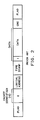
- FIG. 2 illustrates the packet which would be transmitted in the packet switching system of FIG. 1 between customer 100 and customer 110.
- the data portion of the packet illustrated in FIG. 2 would be encrypted by customer 100 before transmission into the packet switching system, but the system adds flag information and the header information that consists of packet identifier, logical address, and time stamp fields.
- the packets in the above-cited U. S. patent are communicated via high-speed digital links across country via trunks such as trunk 118. These trunks could be microwave or satellite links.
- the packets being communicated on trunk 118 would have the format illustrated in FIG. 2. Since the customer is only able to encrypt the data portion of the packet of FIG. 2, the unauthorized personnel could readily break the encryption algorithm.
- a departure in the art is achieved by a packet switching system which encrypts the flags that define the start and end of packets being communicated on links such as high-speed data transmission trunks. Furthermore, a procedure is provided for synchronizing the encryption of the flag information at either end of the trunk by the trunk controllers that connect directly to the high-speed digital trunk.
- the structural embodiment comprises a circuit for encrypting only the flags prior to transmission on a trunk and a circuit for decrypting the flags upon receipt from the trunk.
- the decrypting circuit has a subcircuit for detecting when the decrypting circuit is no longer in flag synchronization with respect to the encrypting circuit. Upon detecting that flag synchronization has been lost, the latter subcircuit initializes the encrypting circuit by transmitting a predetermined packet to the encrypting circuit.
- the encrypting circuit has a subcircuit for detecting the predetermined packet and for generating an initialization signal.
- the encrypting circuit has another subcircuit responsive to the initialization signal for initializing the encrypting circuit to generate a predetermined sequence of encrypted flags.
- the decrypting circuit has a detection subcircuit for detecting the predetermined sequence of encrypted flags.
- the detection subcircuit is responsive to the predetermined sequence to place the decrypting circuit in flag synchronization with the encrypting circuit.
- each flag has a plurality of bytes
- the decrypting circuit has a maintenance subcircuit for maintaining synchronization upon up to a predetermined number of the bytes being incorrect within any particular flag.
- the maintenance subcircuit maintains flag synchronization upon up to a predetermined number of the bytes of the current flag appearing in the data of the current packet.
- a method prevents an unauthorized detection of the start and end of packets being transmitted in a packet switching system which has packet switching networks that are interconnected by trunks. Each network terminates a trunk with trunk controller.
- the method has the steps of only encrypting flags separating packets upon transmission of the packet on a connected trunk and decrypting the encrypted flags upon receipt of the packets from the connected trunk.
- the decrypting step includes the step of synchronizing with encrypted flags.
- the synchronizing step includes the steps of initializing the encrypting step to use a predetermined sequence of flags, detecting the predetermined sequence, and placing the decrypting step in flag synchronization with the encrypting step upon detection of the predetermined sequence.
- system elements when first introduced on a figure, are each designated with a number that uses the figure number as the most significant digits of the element number.
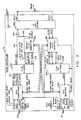
- FIGS. 3 and 4 illustrate the trunk interface portions of trunk controllers 131 and 140 of FIG. 1 as modified by this invention.
- the packets transmitted by trunk controller 131 to trunk controller 140 via trunk 118 are identical in structure to those illustrated in FIG. 2 with the exception that the flag patterns are no longer the same for each packet, but rather are encrypted.
- the encryption of the flag makes it difficult to determine the start and end of individual packets from the data being continuously transmitted via trunk 118.
- the transmitter portion is made up of blocks 301, 302, 303 and 307 and the receiver portion comprises blocks 304, 305 and 306.
- the T1 subsystem 308 provides the interface to trunk 118. More details concerning this interface can be found in the previously referenced U. S. patent and in the Bell System Technical Reference, publication 41451, "High Capacity Terrestrial Digital Service", January, 1983, published by American Telephone and 22, Company.
- trunk controller 131 the transmission from trunk controller 131 to trunk controller 140. It is assumed at this point that the trunk controllers are in synchronization both with respect to the data stream and the flag encryption.
- the trunk controller has a packet to send it transfers the packet to the idle transmitter 301 via the data and write links of cable 310. Before the transfer, the trunk controller must be receiving the ready signal from idle transmitter 301 via cable 310.
- Idle transmitter 301 is responsive to the start of the data to transmit the data select signal via conductor 314 and data via conductor 313 to flag anti-aliasor 303 if the hold signal is not being transmitted from block 303 to block 301 via conductor 315.
- Block 303 is responsive to previously received flag bits from random flag generator, RFG, 302 to perform a standard flag aliasing operation on the data being received via conductor 313 to assure that the start flag does not appear in the transmitted data. After the aliasing operation is performed, block 303 transfers the data via conductor 314 to the T1 subsystem 308 via OR gate 307. After the packet has been transmitted, block 303 detects this fact and transmits the new flag signal via conductor 341 to RFG 302. The latter block is responsive to the latter signal to transmit the end flag to T1 subsystem 308 via conductor 320 and OR gate 307. RFG 302 will continue to transmit flags to T1 subsystem 308 until the toggle signal is transmitted via conductor 319 from block 303.
- Block 303 does not commence transmission of this data until the load flag signal is received via conductor 318 from RFG 302.
- the latter block transmits the load flag signal after it has transmitted the last current flag via cable 317.
- the flags are variable and are being generated by random variable generator 302 in response to an initial seed as will be explained in greater detail with respect to FIG. 9.
- RFR 326 detects a start flag indicating the start of a new packet, it transmits the flag valid signal via conductor 344, blocks 324, and 365, and transfers the flag bits via conductor 346 to block 325.
- the flag valid signal indicates that the flag bits transferred via conductor 346 represented the start flag of a new packet.
- RFR 326 and RFG 302 are in synchronization with respect to the flags.
- the method of achieving synchronization is described in greater detail later.
- RFR 326 receives data, it transfers this data via conductor 345 along with a clock signal on conductor 347 to flag unaliasor 325.
- the latter block recovers the data which had been modified so that the flag did not appear in the data by block 303 and transfers this data to idle receiver 324.
- the latter receiver in turn transfers the information to the remainder of trunk controller 140 via cable 312.
- the current flag to be utilized by flag unaliasor 325 is transferred from RFR 326 via cable 346, and RFR 326 indicates when these bits are valid by transmitting a flag valid signal via conductor 344.
- RFR 326 detects the end flag, it indicates to block 325 that there is no more data by transmitting the hold signal via conductor 342 and stopping the transmission of the clock signal on conductor 347.
- Flag unaliasor 325 transfers the data received from RFR 326 to idle receiver 324 after processing the data.
- Idle receiver 324 is responsive to the data received from block 325 to transfer this data to the remainder of trunk controller 140 via cable 312.
- Data is transferred from trunk controller 140 to trunk controller 131 via trunk 118 in a manner similar to that just described.
- RFG 302 and RFR 326 were in synchronization with respect to the flags. If this synchronization is lost and RFR 326 detects that it is no longer receiving the correct flags, it transmits a reset signal via conductor 350 to idle transmitter 321. Idle transmitter 321 is responsive to the latter signal to transmit a reset packet.
- the latter packet may advantageously comprise data sequences which are not normally used and have been reserved for the reset packet.
- the reset packet is then transmitted via trunk 118 to RFR 306 which processes this packet in the normal manner transferring it via flag unaliasor 325 to idle receiver 304.
- idle receiver 304 transmits a reset signal via conductor 351 to RFG 302.
- the latter block is responsive to the reset signal to reset the random sequence of flag generation.
- RFR 326 had also reset its random sequence of flags.
- RFG 302 starts to transmit an initial flag sequence.
- RFR 326 detects the initial flag sequence and transmits the initial sequence correct signal via conductor 352 to idle transmitter 321.
- the latter block is responsive to this signal to cease transmission of the reset packets.
- idle transmitter 321 upon receiving the reset signal via conductor 350, idle transmitter 321 periodically transmits out reset packets.
- trunk controller 140 The above actions of resyncing the flags can also be accomplished at trunk controller 140 by the transmission of the send user reset signal via cable 330 in trunk controller 140 under either computer control or manual control as is described in greater detail with respect to FIG 5. A similar mechanism is available in trunk controller 131.
- Idle transmitter 301 is illustrated in greater detail in FIG. 5.
- the packets flow through FIFO 501 to data out conductor 313 via multiplexer 507.
- the latter multiplexer is controlled by logic 506 in response to the FIFO full signal FIFO 501 transmitted via conductor 510.
- Logic 506 controls the multiplexer by transmitting the DE signal via conductor 511. Idle packet transmission can be requested when there are no data packets to be transmitted and is requested as follows. If logic 506 receives the send idle signal via cable 310, logic 506 transmits the 15 signal via conductor 514 to idle packet generator 503.
- the latter generator accesses idle packet ROM 502 and transfers the data to conductor 313 via conductor 516 and multiplexer 507.
- Multiplexer 507 is controlled by logic 506 transmitting the IE signal via conductor 512.
- generator 503 transmits the 1O signal via conductor 515 to logic 506 thus informing the latter unit that the packet has been completely transmitted. It then stops transmitting the IE signal on conductor 512 to multiplexer 507 and retransmits the DE signal on conductor 511.
- Logic 506 is responsive to the transmission of the send user reset signal on cable 310 to generate the user reset signal transmitted via conductor 360. Also, in response to the send user reset signal, logic 506 activates reset packet generator 505 by sending the RS signal via conductor 517. The latter generator is responsive to the RS signal to access reset flag ROM 504 for the sequence of bytes which constitute the reset sequence.
- Generator 505 transmits the data to conductor 313 via conductor 519 and multiplexer 507.
- Logic 506 controls multiplexer 507 by transmitting the RE signal via conductor 513. After the packet generator 505 has finished transmitting the reset sequence, it indicates this fact to logic 506 by transmitting the RO signal via the conductor 518.
- the reset packet generated in this manner has the last byte consisting of all ones indicating that it was a user reset that caused the generation of the reset sequence. If the reset sequence occurs as a result of the generation of the reset signal transmitted via conductor 361, then, the last byte of the sequence will consist of all zeros.
- An important aspect of the system is the automatic generation of a user reset and transmission of user reset packet after a flxed number of flags have been transmitted by the circuit illustrated in FIG. 5.
- the receipt of the user reset packet results in the seed/key registers in random flag generators 302 and 322 being increment resulting in a new flag sequence being generated.
- Counter 508 counts the number of flags that have been transmitted by RFG 302 in response to the clock signal received from T1 subsystem 308 and a signal transmitted via conductor 522 indicating that logic 506 is not presently controlling the transmission of a packet data via multiplexer 507.
- counter 508 When counter 508 has counted to a predetermined limit, it transmits a signal to logic 506 via conductor 521 that causes the latter logic unit to respond as if it had received a user reset signal via conductor 361. Logic 506 then generates a user reset signal on conductor 361. Note that transmission on conductor 361 is bilateral, either block 301 or 306 can generate a user reset signal and transmit the user reset signal on conductor 361. This causes the previously described actions by generator 505 to be executed. Further, logic 506 performs the necessary operations in response to signals transmitted via conductors 312 and 315.
- RFR 326 is illustrated in greater detail in FIG. 6.
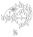
- Logic block 627 provides overall control of RFR 326; and FIG. 7 illustrates, in state diagram form, the various states which logic block 627 of FIG. 6 can occupy.
- Blocks 629 through 634 are responsible for generating the flags with each flag having five bytes.
- the first multibyte shift register is used to receive the data from input conductor 348 and includes shift registers 620 through 624. These shift registers function as one overall shift register with each shift register holding eight bits or one byte of data.
- the multibyte comparator includes comparators 610 through 614. The mismatch or match signals are transmitted from comparators 610 through 614 via conductors 640 through 644, respectively.
- the second multibyte shift register is used to store and shift the flag bytes and includes shift registers 600 through 604.
- Shift register 600 is loaded one byte at a time from flag memory 633 under control of a signal received from logic block 627 via conductor 655 into the load input of shift register 600.
- Shift registers 600 through 604 perform a shift operation in response to a clocking signal from logic block 627 via conductor 646.
- Shift registers 600 through 604 and 620 through 624 can be cleared to all zeros by the transmission of a signal from logic block 627 via conductor 645.
- logic block 627 is attempting to achieve synchronization first at the bit level and then at the byte level with flags that are being received via conductor 348. For each bit received via 348 by shift register 620, logic block 627 loads the first byte of the flag into shift register 600 by transmission of a signal via conductor 655. The first byte of the flag is selected by logic block 627 clearing counter 634. Counter 634 is used to access the individual bytes of flag memory 633. The determination of which flag is to be utilized from flag memory 633 is in response to address information received from random number generator 630 via conductor 651. The control of random number generator 630 will be discussed later.
- logic block 627 When comparator 610 indicates a match for a particular sequence of bits in shift register 620, logic block 627 causes shift register 600 to shift this first byte into shift register 601 in synchronization with the receipt of next byte via conductor 348. Logic block 627 controls that shift operation by transmission of clock signals via conductor 646 to shift registers 600 through 604. This match on the first flag byte indicates that potentially the first flag byte has been identified but the other flag bytes must be found in the proper sequence before flag synchronization is achieved.
- logic block 627 loads the second flag byte from flag memory 633 by properly controlling counter 634 and the transmission of a signal on conductor 655. The matching process continues until all five bytes of the flag have been identified as being received via conductor 348. Logic block 627 remains in compare state 702 via path 711 during this process. If all five bytes of the flag are not received correctly, the process is repeated.
- logic block 627 enters flag state 703 via path 712. Absent errors occurring on the data transmission via trunk 118, logic block 627 remains in state 703 until four bytes of data have been received via conductor 348 and then transfers to data state 704. This condition is indicated on conductors 640 through 644 by a hexadecimal 10 where conductor 640 represents the least significant byte. This condition indicates that the next data byte received will result in the first data byte being shifted out of shift register 624 via conductor 654.
- logic block 627 After logic block 627 is in the data state 704 and the first bit of the first byte of data is being outputted by shift register 624 onto conductor 654, logic block 627 transmits the hold signal via conductor 342 which enables the data to be transmitted on conductor 345 via AND gate 625 and conductor 654 and the clock signals on conductor 347 via AND gate 626. In addition, logic block 627 transmits the initial sequence correct signal on conductor 352, the flag valid signal on conductor 344 and the flag bits serially on conductor 346 from the output shift register 604. The flag bits are constantly being sent on conductor 346. They will stop when flag valid signal on conductor 344 becomes active which indicates transmission of a valid start flag on conductor 346.
- Logic block 627 remains in data state 704 until the next flag which consists of five bytes is detected by comparators 610 through 614. When the flag is detected, logic block 627 transfers back to flag state 703 via path 716. While logic block 627 is in data state 704, it is constantly checking for the next flag by comparing the contents of shift registers 600 through 604 with the contents of shift registers 620 through 624. When the five bytes of a flag are detected, logic block 627 ceases to transmit the hold signal via conductor 342. Absent transmission errors, when all five bytes of the flag have been detected by comparators 610 through 614, these comparators transmit to logic block 627 via conductors 640 through 644 a hexadecimal 1E. Absent transmission errors, logic block 627 remains in flag state 703 until the comparators 610 through 614 transmit a hexadecimal 10 to logic block 627.
- logic block 627 is in data state 704. As long as comparators 610 through 614 indicate that for any sequence of five bytes of data that less than two flag bytes have been detected in this sequence, logic block 627 remains in the data state via path 715. However, if comparators 610 through 614 detect that three or more bytes of the flag have been detected in the current five byte sequence, logic state 627 enters count state 705 via path 717. In state 705, logic block 627 increments its internal counter and transfers to flag state 703 via path 718.
- logic block 627 if logic block 627 is in flag state 703 and detects two or less bytes of the flag in the current five byte sequence in shift registers 620 through 624, it remains in flag state 703 via path 713. However, if three or more bytes of the flag are detected in the current five byte sequence in shift registers 620 through 624, logic block 627 transfers to count state 706 via path 719. In count state 706, the internal counter is updated. If the internal counter is less than the predetermined value, the logic block immediately transfers into data state 704 via path 720.
- error state 707 is entered via path 725 or 724, respectively.
- logic block 727 transmits a reset signal via conductor 350 and transmits the packet abort signal via conductor 349.
- logic block 627 ceases to transmit the flag valid signal via conductor 344 and hold signal via conductor 342.
- Logic block 627 transfers flom error state 707 to flush state 708 via path 726. While in state 708, logic block 627 transmits a signal via conductor 645 which clears shift registers 600 through 604 and 620 through 624. In addition, logic block 627 transmits a signal via conductor 647 to register 629. This signal causes register 629 to be reset to the initial value causing the initial seed and key to be accessed from seed memory 632 and key memory 631. The outputs of these two memories is received by random number generator 630 via paths 652 and 653. In response, random number generator 630 accesses the initial flag from flag memory 633 via path 651. Once these operations are accomplished, logic block 627 transfers to reset state via path 727.
- logic block 627 can enter error state 707 via path 723 from data state 704 if logic block 627 detects that a packet has exceeded the maximum length.
- logic block 627 can be driven out of flag state 703 or data state 704 to flush state 708 via paths 721 or 722, respectively, upon receipt of a reset or user reset signal received via conductors 350 or 370.
- Conductor 350 is a bilateral path. The generation of these signals is described with respect to the idle transmitter 301 of FIG. 5.
- the user reset causes logic block 627 to transfer to the state 709 via path 729 from flush state 708. State 709 increments the contents of register 629 hence causing a change of the seed and key that is utilized by random number generator 630.
- FIG. 8 illustrates, in greater detail, idle receiver 324 of FIG. 3.
- data is received via conductor 358 from flag unaliasor 325, it is clocked into register 808.
- Geneva byte is then compared by the three ROM-comparator pairs, 802 and 803, 804 and 805, and 806 and 807 that check for the idle, restart, and reset patterns, respectively.
- the restart pattern is contained in a user reset packet. If one of these patterns is detected, a signal is transmitted to logic 809 that increments the ROMs to the next word of the pattern. For example, if the first word of the reset pattern is detected, the reset compare signal is transmitted via conductor 810 to logic 809 fom comparator 807.
- logic 809 then transmits the increment signal via conductor 811 that increments ROM 806 to the next byte of the reset pattern. After logic 809 determines that the entire pattern has been received, it then transmits the appropriate signal on either conductor 359 or 360. In addition, the data is transferred from register 808 to FIFO 801 where it is subsequently communicated via cable 312. ROM-comparator pairs 802 and 803 and 804 and 805 function in a similar manner.
- Idle Receiver 324 receives the packet abort signal via conductor 349 from RFR 326 for a predetermined period of time, it generates the reset 0 signal on conductor 359. This will synchronize the system if both RR 326 and RR 306 have lost flag synclironization.
- RFG 302 is illustrated in greater detail in FIG. 9.
- logic circuit 905 is responsive to the new flag signal received via conductor 341 to generate the increment signal via conductor 910 to random number generator 904.
- Random number generator 904 is responsive to the latter signal and the seed and key received from seed memory 901 and key memory 902, respectively, to generate address signals that are transmitted via cable 912 to flag memory 906.
- These address signals access one of the flags stored in flag memory 906 that is then transmitted to parallel-to-serial converter 907 and block 303 via cable 317.
- Parallel-to-serial converter 907 converts the flag into a serial stream which is then transmitted via AND gate 908 to OR gate 307 via conductor 320.
- logic 905 transmits the toggle signal via conductor 319 to block 303.
- Logic 905 is responsive to a user reset signal received via conductor 351 to transmit the INIT signal via conductor 911 to random number generator 904. This causes random number generator 904 to start the random sequence for the next flag based on the current seed being received from the seed memory 901 and the key memory 902, respectively.
- the increment seed/key signal is transmitted via conductor 909 which causes seed/key register 903 to be incremented. If a reset signal is received via connector 351, logic 905 transmits the INIT signal via conductor 911 and also transmits a signal via conductor 913 that resets the seed/key register to a known value.
Abstract
Description
- Data encryption is well known and has been in use for a number of years. A problem arises in packet switching networks in that whereas it is possible to encrypt the data contained within the packet, the packet itself, as it is transmitted between packet switching networks via interconnecting trunks, is defined by flag and header information. Hence, the encryption of the data is not as effective since the amount of data being encrypted is relatively small, and the probability of the encryption algorithm being broken is greatly increased. Indeed, the packet header information contains the logical channel number which allows the identification of which packets are associated with particular frames being transmitted between packet switching systems.
- One such prior art packet switching system is disclosed in U. S. Patent 4,494,230, and is illustrated in FIG. 1. FIG. 2 illustrates the packet which would be transmitted in the packet switching system of FIG. 1 between
customer 100 and customer 110. The data portion of the packet illustrated in FIG. 2 would be encrypted bycustomer 100 before transmission into the packet switching system, but the system adds flag information and the header information that consists of packet identifier, logical address, and time stamp fields. The packets in the above-cited U. S. patent are communicated via high-speed digital links across country via trunks such astrunk 118. These trunks could be microwave or satellite links. In the event that unauthorized personnel should gain access totrunk 118, the packets being communicated ontrunk 118 would have the format illustrated in FIG. 2. Since the customer is only able to encrypt the data portion of the packet of FIG. 2, the unauthorized personnel could readily break the encryption algorithm. - From the foregoing, it can be seen that there exists the need for a method of not only encrypting the data within a packet, but for encrypting the entire transmission path over which the packets flow, thus also encrypting the flag and header information. Whereas the present public key encryption systems perform extremely well in absence of errors, these systems require a large amount of processing, and more efficient and less intense processing algorithms are desirable. In the presence of errors, packets are likely to be lost during periods of re-synchronization using a public key encryption system.
- In an illustrative method and structural embodiment, a departure in the art is achieved by a packet switching system which encrypts the flags that define the start and end of packets being communicated on links such as high-speed data transmission trunks. Furthermore, a procedure is provided for synchronizing the encryption of the flag information at either end of the trunk by the trunk controllers that connect directly to the high-speed digital trunk.
- Advantageously, the structural embodiment comprises a circuit for encrypting only the flags prior to transmission on a trunk and a circuit for decrypting the flags upon receipt from the trunk. The decrypting circuit has a subcircuit for detecting when the decrypting circuit is no longer in flag synchronization with respect to the encrypting circuit. Upon detecting that flag synchronization has been lost, the latter subcircuit initializes the encrypting circuit by transmitting a predetermined packet to the encrypting circuit.
- Advantageously, the encrypting circuit has a subcircuit for detecting the predetermined packet and for generating an initialization signal. The encrypting circuit has another subcircuit responsive to the initialization signal for initializing the encrypting circuit to generate a predetermined sequence of encrypted flags.
- Also, the decrypting circuit has a detection subcircuit for detecting the predetermined sequence of encrypted flags. The detection subcircuit is responsive to the predetermined sequence to place the decrypting circuit in flag synchronization with the encrypting circuit.
- In addition, each flag has a plurality of bytes, and the decrypting circuit has a maintenance subcircuit for maintaining synchronization upon up to a predetermined number of the bytes being incorrect within any particular flag. Also, the maintenance subcircuit maintains flag synchronization upon up to a predetermined number of the bytes of the current flag appearing in the data of the current packet.
- A method prevents an unauthorized detection of the start and end of packets being transmitted in a packet switching system which has packet switching networks that are interconnected by trunks. Each network terminates a trunk with trunk controller. The method has the steps of only encrypting flags separating packets upon transmission of the packet on a connected trunk and decrypting the encrypted flags upon receipt of the packets from the connected trunk. The decrypting step includes the step of synchronizing with encrypted flags. The synchronizing step includes the steps of initializing the encrypting step to use a predetermined sequence of flags, detecting the predetermined sequence, and placing the decrypting step in flag synchronization with the encrypting step upon detection of the predetermined sequence.
- In general, system elements, when first introduced on a figure, are each designated with a number that uses the figure number as the most significant digits of the element number.
- FIG. 1 illustrates, in block diagram form, a prior art communication system for performing packet switching;
- FIG. 2 illustrates the contents of a prior art packet which is routed via the system illustrated in FIG. 1;
- FIG. 3 illustrates a portion of
trunk controller 131 of FIG. 1 in greater detail; - FIG. 4 illustrates a portion of
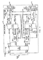
trunk controller 140 of FIG. 1 in greater detail; - FIG. 5 illustrates, in greater detail,
idle transmitter 301 of FIG. 3; - FIG. 6 illustrates, in greater detail, random flag receiver (RFR) 306 of FIG. 3;
- FIG. 7 illustrates, in state diagram form, the operation of
RFR 306; - FIG. 8 illustrates, in greater detail,
idle receiver 324 of FIG. 4; and - FIG. 9 illustrates, in block diagram form, random
flag generator RFG 302 of FIG. 3. - FIGS. 3 and 4 illustrate the trunk interface portions of
trunk controllers trunk controller 131 totrunk controller 140 viatrunk 118 are identical in structure to those illustrated in FIG. 2 with the exception that the flag patterns are no longer the same for each packet, but rather are encrypted. The encryption of the flag makes it difficult to determine the start and end of individual packets from the data being continuously transmitted viatrunk 118. The transmitter portion is made up ofblocks blocks T1 subsystem 308 provides the interface totrunk 118. More details concerning this interface can be found in the previously referenced U. S. patent and in the Bell System Technical Reference, publication 41451, "High Capacity Terrestrial Digital Service", January, 1983, published by American Telephone and Telegraph Company. - Consider in greater detail the functions periorined by the blocks of FIG. 3. First, consider the transmission from
trunk controller 131 totrunk controller 140. It is assumed at this point that the trunk controllers are in synchronization both with respect to the data stream and the flag encryption. When the trunk controller has a packet to send it transfers the packet to theidle transmitter 301 via the data and write links ofcable 310. Before the transfer, the trunk controller must be receiving the ready signal fromidle transmitter 301 viacable 310.Idle transmitter 301 is responsive to the start of the data to transmit the data select signal viaconductor 314 and data viaconductor 313 to flag anti-aliasor 303 if the hold signal is not being transmitted fromblock 303 toblock 301 viaconductor 315.Block 303 is responsive to previously received flag bits from random flag generator, RFG, 302 to perform a standard flag aliasing operation on the data being received viaconductor 313 to assure that the start flag does not appear in the transmitted data. After the aliasing operation is performed,block 303 transfers the data viaconductor 314 to theT1 subsystem 308 via ORgate 307. After the packet has been transmitted,block 303 detects this fact and transmits the new flag signal viaconductor 341 to RFG 302. The latter block is responsive to the latter signal to transmit the end flag toT1 subsystem 308 viaconductor 320 and ORgate 307. RFG 302 will continue to transmit flags toT1 subsystem 308 until the toggle signal is transmitted viaconductor 319 fromblock 303. The transmission of the toggle signal indicates thatblock 303 has information to transmit toT1 subsystem 308.Block 303 does not commence transmission of this data until the load flag signal is received viaconductor 318 fromRFG 302. The latter block transmits the load flag signal after it has transmitted the last current flag viacable 317. The flags are variable and are being generated byrandom variable generator 302 in response to an initial seed as will be explained in greater detail with respect to FIG. 9. - At the receiving end, as illustrated in FIG. 4, as the data is being received via
trunk 118 byT1 subsystem 328, the latter subsystem recovers the clock and transfers the data viaconductor 348 to random flag receiver, RFR, 326. WhenRFR 326 detects a start flag indicating the start of a new packet, it transmits the flag valid signal viaconductor 344, blocks 324, and 365, and transfers the flag bits viaconductor 346 to block 325. The flag valid signal indicates that the flag bits transferred viaconductor 346 represented the start flag of a new packet. AfterRFR 326 has received the start flag for that packet, it commences to search for the start flag of the next packet. At this time, it has been assumed thatRFR 326 andRFG 302 are in synchronization with respect to the flags. The method of achieving synchronization is described in greater detail later. AsRFR 326 receives data, it transfers this data viaconductor 345 along with a clock signal onconductor 347 toflag unaliasor 325. The latter block recovers the data which had been modified so that the flag did not appear in the data byblock 303 and transfers this data toidle receiver 324. The latter receiver in turn transfers the information to the remainder oftrunk controller 140 viacable 312. - The current flag to be utilized by
flag unaliasor 325 is transferred fromRFR 326 viacable 346, andRFR 326 indicates when these bits are valid by transmitting a flag valid signal viaconductor 344. WhenRFR 326 detects the end flag, it indicates to block 325 that there is no more data by transmitting the hold signal viaconductor 342 and stopping the transmission of the clock signal onconductor 347. -
Flag unaliasor 325 transfers the data received fromRFR 326 toidle receiver 324 after processing the data.Idle receiver 324 is responsive to the data received fromblock 325 to transfer this data to the remainder oftrunk controller 140 viacable 312. - Data is transferred from
trunk controller 140 totrunk controller 131 viatrunk 118 in a manner similar to that just described. - The previous discussion has assumed that
RFG 302 andRFR 326 were in synchronization with respect to the flags. If this synchronization is lost andRFR 326 detects that it is no longer receiving the correct flags, it transmits a reset signal viaconductor 350 toidle transmitter 321.Idle transmitter 321 is responsive to the latter signal to transmit a reset packet. The latter packet may advantageously comprise data sequences which are not normally used and have been reserved for the reset packet. The reset packet is then transmitted viatrunk 118 toRFR 306 which processes this packet in the normal manner transferring it viaflag unaliasor 325 toidle receiver 304. - In response to the reset packet,
idle receiver 304 transmits a reset signal viaconductor 351 toRFG 302. The latter block is responsive to the reset signal to reset the random sequence of flag generation. Note that upon generating the reset signal,RFR 326 had also reset its random sequence of flags. Also in response to the reset signal,RFG 302 starts to transmit an initial flag sequence.RFR 326 detects the initial flag sequence and transmits the initial sequence correct signal viaconductor 352 toidle transmitter 321. The latter block is responsive to this signal to cease transmission of the reset packets. Note, upon receiving the reset signal viaconductor 350,idle transmitter 321 periodically transmits out reset packets. - The above actions of resyncing the flags can also be accomplished at
trunk controller 140 by the transmission of the send user reset signal viacable 330 intrunk controller 140 under either computer control or manual control as is described in greater detail with respect to FIG 5. A similar mechanism is available intrunk controller 131. -
Idle transmitter 301 is illustrated in greater detail in FIG. 5. During normal operations, when data is being transferred from the remainder oftrunk controller 131 throughidle transmitter 301, the packets flow throughFIFO 501 to data outconductor 313 viamultiplexer 507. The latter multiplexer is controlled bylogic 506 in response to the FIFOfull signal FIFO 501 transmitted viaconductor 510.Logic 506 controls the multiplexer by transmitting the DE signal viaconductor 511. Idle packet transmission can be requested when there are no data packets to be transmitted and is requested as follows. Iflogic 506 receives the send idle signal viacable 310,logic 506 transmits the 15 signal via conductor 514 toidle packet generator 503. In response, the latter generator accessesidle packet ROM 502 and transfers the data toconductor 313 viaconductor 516 andmultiplexer 507.Multiplexer 507 is controlled bylogic 506 transmitting the IE signal viaconductor 512. After the idle packet has been transmitted,generator 503 transmits the 1O signal via conductor 515 tologic 506 thus informing the latter unit that the packet has been completely transmitted. It then stops transmitting the IE signal onconductor 512 tomultiplexer 507 and retransmits the DE signal onconductor 511. -
Logic 506 is responsive to the transmission of the send user reset signal oncable 310 to generate the user reset signal transmitted viaconductor 360. Also, in response to the send user reset signal,logic 506 activates resetpacket generator 505 by sending the RS signal viaconductor 517. The latter generator is responsive to the RS signal to accessreset flag ROM 504 for the sequence of bytes which constitute the reset sequence. -
Generator 505 transmits the data toconductor 313 viaconductor 519 andmultiplexer 507.Logic 506 controls multiplexer 507 by transmitting the RE signal viaconductor 513. After thepacket generator 505 has finished transmitting the reset sequence, it indicates this fact tologic 506 by transmitting the RO signal via theconductor 518. The reset packet generated in this manner has the last byte consisting of all ones indicating that it was a user reset that caused the generation of the reset sequence. If the reset sequence occurs as a result of the generation of the reset signal transmitted via conductor 361, then, the last byte of the sequence will consist of all zeros. - An important aspect of the system is the automatic generation of a user reset and transmission of user reset packet after a flxed number of flags have been transmitted by the circuit illustrated in FIG. 5. The receipt of the user reset packet results in the seed/key registers in
random flag generators RFG 302 in response to the clock signal received fromT1 subsystem 308 and a signal transmitted viaconductor 522 indicating thatlogic 506 is not presently controlling the transmission of a packet data viamultiplexer 507. Whencounter 508 has counted to a predetermined limit, it transmits a signal tologic 506 via conductor 521 that causes the latter logic unit to respond as if it had received a user reset signal via conductor 361.Logic 506 then generates a user reset signal on conductor 361. Note that transmission on conductor 361 is bilateral, either block 301 or 306 can generate a user reset signal and transmit the user reset signal on conductor 361. This causes the previously described actions bygenerator 505 to be executed. Further,logic 506 performs the necessary operations in response to signals transmitted viaconductors -
RFR 326 is illustrated in greater detail in FIG. 6.Logic block 627 provides overall control ofRFR 326; and FIG. 7 illustrates, in state diagram form, the various states whichlogic block 627 of FIG. 6 can occupy.Blocks 629 through 634 are responsible for generating the flags with each flag having five bytes. There are two multibyte shift registers and one multibyte comparator inRFR 326. The first multibyte shift register is used to receive the data frominput conductor 348 and includesshift registers 620 through 624. These shift registers function as one overall shift register with each shift register holding eight bits or one byte of data. The multibyte comparator includescomparators 610 through 614. The mismatch or match signals are transmitted fromcomparators 610 through 614 viaconductors 640 through 644, respectively. The second multibyte shift register is used to store and shift the flag bytes and includesshift registers 600 through 604.Shift register 600 is loaded one byte at a time fromflag memory 633 under control of a signal received fromlogic block 627 viaconductor 655 into the load input ofshift register 600. Shift registers 600 through 604 perform a shift operation in response to a clocking signal fromlogic block 627 viaconductor 646. Shift registers 600 through 604 and 620 through 624 can be cleared to all zeros by the transmission of a signal fromlogic block 627 viaconductor 645. - Consider now the operation of
RFR 326 assuming thatlogic block 627 is in comparestate 702 of FIG. 7. In that state,logic block 627 is attempting to achieve synchronization first at the bit level and then at the byte level with flags that are being received viaconductor 348. For each bit received via 348 byshift register 620, logic block 627 loads the first byte of the flag intoshift register 600 by transmission of a signal viaconductor 655. The first byte of the flag is selected bylogic block 627clearing counter 634.Counter 634 is used to access the individual bytes offlag memory 633. The determination of which flag is to be utilized fromflag memory 633 is in response to address information received fromrandom number generator 630 viaconductor 651. The control ofrandom number generator 630 will be discussed later. - When
comparator 610 indicates a match for a particular sequence of bits inshift register 620,logic block 627 causesshift register 600 to shift this first byte intoshift register 601 in synchronization with the receipt of next byte viaconductor 348.Logic block 627 controls that shift operation by transmission of clock signals viaconductor 646 to shiftregisters 600 through 604. This match on the first flag byte indicates that potentially the first flag byte has been identified but the other flag bytes must be found in the proper sequence before flag synchronization is achieved. - After the second byte has been received from
conductor 348, logic block 627 loads the second flag byte fromflag memory 633 by properly controllingcounter 634 and the transmission of a signal onconductor 655. The matching process continues until all five bytes of the flag have been identified as being received viaconductor 348.Logic block 627 remains in comparestate 702 via path 711 during this process. If all five bytes of the flag are not received correctly, the process is repeated. - Once all
comparators 611 through 614 indicate matches onconductors 640 through 644, respectively,logic block 627 entersflag state 703 viapath 712. Absent errors occurring on the data transmission viatrunk 118,logic block 627 remains instate 703 until four bytes of data have been received viaconductor 348 and then transfers todata state 704. This condition is indicated onconductors 640 through 644 by a hexadecimal 10 whereconductor 640 represents the least significant byte. This condition indicates that the next data byte received will result in the first data byte being shifted out ofshift register 624 viaconductor 654. - After
logic block 627 is in thedata state 704 and the first bit of the first byte of data is being outputted byshift register 624 ontoconductor 654,logic block 627 transmits the hold signal viaconductor 342 which enables the data to be transmitted onconductor 345 via ANDgate 625 andconductor 654 and the clock signals onconductor 347 via ANDgate 626. In addition,logic block 627 transmits the initial sequence correct signal onconductor 352, the flag valid signal onconductor 344 and the flag bits serially onconductor 346 from theoutput shift register 604. The flag bits are constantly being sent onconductor 346. They will stop when flag valid signal onconductor 344 becomes active which indicates transmission of a valid start flag onconductor 346. -
Logic block 627 remains indata state 704 until the next flag which consists of five bytes is detected bycomparators 610 through 614. When the flag is detected,logic block 627 transfers back toflag state 703 viapath 716. Whilelogic block 627 is indata state 704, it is constantly checking for the next flag by comparing the contents ofshift registers 600 through 604 with the contents ofshift registers 620 through 624. When the five bytes of a flag are detected,logic block 627 ceases to transmit the hold signal viaconductor 342. Absent transmission errors, when all five bytes of the flag have been detected bycomparators 610 through 614, these comparators transmit to logic block 627 viaconductors 640 through 644 a hexadecimal 1E. Absent transmission errors,logic block 627 remains inflag state 703 until thecomparators 610 through 614 transmit a hexadecimal 10 tologic block 627. - The previous discussion had assumed that no transmission errors were occurring on
trunk 118. As long as both trunk controllers on either end oftrunk 118 are in flag synchronization and absent transmission errors, the bytes of a flag should never occur in data because of the actions ofblock 303 and similar blocks. However, it is possible for transmission errors to occur, andlogic block 627 assumes the occurrence of these transmission errors and allows up to two bytes of a flag to be incorrect before assuming that flag synchronization has been lost.Logic block 627, however, maintains a count of these types of errors; and when the count exceeds a predetermined value, which is assumed to be five in the present system, then,logic block 627 declares that flag synchronization has been lost. The remaining portion of the receiving trunk controller uses standard error detection and correction methods to detect and recover from errors in the data. - Assuming transmission errors, consider the situation where
logic block 627 is indata state 704. As long ascomparators 610 through 614 indicate that for any sequence of five bytes of data that less than two flag bytes have been detected in this sequence,logic block 627 remains in the data state viapath 715. However, ifcomparators 610 through 614 detect that three or more bytes of the flag have been detected in the current five byte sequence,logic state 627 enterscount state 705 viapath 717. Instate 705,logic block 627 increments its internal counter and transfers toflag state 703 viapath 718. - Similarly, if
logic block 627 is inflag state 703 and detects two or less bytes of the flag in the current five byte sequence inshift registers 620 through 624, it remains inflag state 703 viapath 713. However, if three or more bytes of the flag are detected in the current five byte sequence inshift registers 620 through 624,logic block 627 transfers to countstate 706 viapath 719. Incount state 706, the internal counter is updated. If the internal counter is less than the predetermined value, the logic block immediately transfers intodata state 704 viapath 720. - If in either count
state error state 707 is entered viapath error state 707,logic block 727 transmits a reset signal viaconductor 350 and transmits the packet abort signal viaconductor 349. In addition,logic block 627 ceases to transmit the flag valid signal viaconductor 344 and hold signal viaconductor 342. -
Logic block 627 transfersflom error state 707 to flushstate 708 viapath 726. While instate 708,logic block 627 transmits a signal viaconductor 645 which clearsshift registers 600 through 604 and 620 through 624. In addition,logic block 627 transmits a signal via conductor 647 to register 629. This signal causesregister 629 to be reset to the initial value causing the initial seed and key to be accessed fromseed memory 632 andkey memory 631. The outputs of these two memories is received byrandom number generator 630 viapaths random number generator 630 accesses the initial flag fromflag memory 633 viapath 651. Once these operations are accomplished,logic block 627 transfers to reset state viapath 727. - Also,
logic block 627 can entererror state 707 via path 723 from data state 704 iflogic block 627 detects that a packet has exceeded the maximum length. - In addition,
logic block 627 can be driven out offlag state 703 ordata state 704 to flushstate 708 viapaths conductors Conductor 350 is a bilateral path. The generation of these signals is described with respect to theidle transmitter 301 of FIG. 5. The user reset causeslogic block 627 to transfer to thestate 709 viapath 729 fromflush state 708.State 709 increments the contents ofregister 629 hence causing a change of the seed and key that is utilized byrandom number generator 630. - FIG. 8 illustrates, in greater detail,
idle receiver 324 of FIG. 3. As data is received viaconductor 358 fromflag unaliasor 325, it is clocked intoregister 808. Fach byte is then compared by the three ROM-comparator pairs, 802 and 803, 804 and 805, and 806 and 807 that check for the idle, restart, and reset patterns, respectively. The restart pattern is contained in a user reset packet. If one of these patterns is detected, a signal is transmitted tologic 809 that increments the ROMs to the next word of the pattern. For example, if the first word of the reset pattern is detected, the reset compare signal is transmitted viaconductor 810 tologic 809 fomcomparator 807.logic 809 then transmits the increment signal viaconductor 811 thatincrements ROM 806 to the next byte of the reset pattern. Afterlogic 809 determines that the entire pattern has been received, it then transmits the appropriate signal on eitherconductor register 808 toFIFO 801 where it is subsequently communicated viacable 312. ROM-comparator pairs - If
Idle Receiver 324 receives the packet abort signal viaconductor 349 fromRFR 326 for a predetermined period of time, it generates thereset 0 signal onconductor 359. This will synchronize the system if bothRR 326 andRR 306 have lost flag synclironization. -
RFG 302 is illustrated in greater detail in FIG. 9. Duiing normal operation,logic circuit 905 is responsive to the new flag signal received viaconductor 341 to generate the increment signal viaconductor 910 torandom number generator 904.Random number generator 904 is responsive to the latter signal and the seed and key received fromseed memory 901 andkey memory 902, respectively, to generate address signals that are transmitted viacable 912 toflag memory 906. These address signals access one of the flags stored inflag memory 906 that is then transmitted to parallel-to-serial converter 907 and block 303 viacable 317. Parallel-to-serial converter 907 converts the flag into a serial stream which is then transmitted via ANDgate 908 to ORgate 307 viaconductor 320. In addition,logic 905 transmits the toggle signal viaconductor 319 to block 303. -
Logic 905 is responsive to a user reset signal received viaconductor 351 to transmit the INIT signal viaconductor 911 torandom number generator 904. This causesrandom number generator 904 to start the random sequence for the next flag based on the current seed being received from theseed memory 901 and thekey memory 902, respectively. In addition, the increment seed/key signal is transmitted viaconductor 909 which causes seed/key register 903 to be incremented. If a reset signal is received viaconnector 351,logic 905 transmits the INIT signal viaconductor 911 and also transmits a signal viaconductor 913 that resets the seed/key register to a known value.
Claims (13)
CHARACTERIZED IN THAT
a circuit (301, 302, 303) for encrypting only flags separating packets upon transmission of said packets; and
a circuit (304, 305, 306) for decrypting said randomly encoded flags upon receipt of said packets and said flags.
said synchronizing subcircuit comprises a subcircuit (600-604, 610-614, 620-624, 630-634) for detecting said predetertmined sequence of said randomly encrypted flags thereby achieving flag synchronization.
a circuit (304) responsive to the detection of said loss of said flag synchronization for initializing said encrypting circuit.
said encrypting circuit further comprises a subcircuit (806) responsive to said predetermined packet for initializing said encrypting means.
CHARACTERIZED IN THAT
only encrypting flags separating packets upon transmission of said packets; and
decrypting said encrypted flags upon receipt of said packets and said flags.
said synchronizing step comprises the step of detecting said predetermined flag pattern thereby achieving flag synchronization.
initializing said encrypting step in response to the detection of the loss of said flag synchronization.
said encrypting step further comprises the step of restarting to initialize said encrypting step in response to said predetermined packet.
Applications Claiming Priority (2)
| Application Number | Priority Date | Filing Date | Title |
|---|---|---|---|
| US07/247,121 US4910777A (en) | 1988-09-20 | 1988-09-20 | Packet switching architecture providing encryption across packets |
| US247121 | 1988-09-20 |
Publications (3)
| Publication Number | Publication Date |
|---|---|
| EP0360478A2 true EP0360478A2 (en) | 1990-03-28 |
| EP0360478A3 EP0360478A3 (en) | 1992-07-22 |
| EP0360478B1 EP0360478B1 (en) | 1997-02-26 |
Family
ID=22933643
Family Applications (1)
| Application Number | Title | Priority Date | Filing Date |
|---|---|---|---|
| EP89309224A Expired - Lifetime EP0360478B1 (en) | 1988-09-20 | 1989-09-12 | A packet switching architecture providing encryption across packets |
Country Status (9)
| Country | Link |
|---|---|
| US (1) | US4910777A (en) |
| EP (1) | EP0360478B1 (en) |
| JP (1) | JPH0683262B2 (en) |
| KR (1) | KR900005720A (en) |
| AT (1) | ATE149274T1 (en) |
| CA (1) | CA1321819C (en) |
| DE (1) | DE68927788T2 (en) |
| HK (1) | HK119897A (en) |
| SG (1) | SG42923A1 (en) |
Cited By (1)
| Publication number | Priority date | Publication date | Assignee | Title |
|---|---|---|---|---|
| WO1995012264A1 (en) * | 1993-10-25 | 1995-05-04 | Koninklijke Ptt Nederland N.V. | Device for processing data packets |
Families Citing this family (12)
| Publication number | Priority date | Publication date | Assignee | Title |
|---|---|---|---|---|
| GB9015799D0 (en) * | 1990-07-18 | 1991-06-12 | Plessey Telecomm | A data communication system |
| US5440633A (en) * | 1993-08-25 | 1995-08-08 | International Business Machines Corporation | Communication network access method and system |
| DE19515680A1 (en) * | 1995-04-28 | 1996-10-31 | Sel Alcatel Ag | Encoder and decoder for flow of news in packets |
| US5757924A (en) * | 1995-09-18 | 1998-05-26 | Digital Secured Networks Techolognies, Inc. | Network security device which performs MAC address translation without affecting the IP address |
| US8079953B2 (en) * | 1996-06-17 | 2011-12-20 | Cybernet Systems Corporation | General-purpose medical instrumentation |
| EP0951767A2 (en) | 1997-01-03 | 1999-10-27 | Fortress Technologies, Inc. | Improved network security device |
| DE19820525A1 (en) | 1998-05-08 | 1999-11-11 | Alcatel Sa | Method, software module, interface device, terminal and server for forwarding control of packets of completed packet sequences of packet-switched networks |
| US6980658B1 (en) * | 1999-09-30 | 2005-12-27 | Qualcomm Incorporated | Method and apparatus for encrypting transmissions in a communication system |
| JP2002055604A (en) * | 2000-08-11 | 2002-02-20 | Trinity Communication Inc | Data protection processing device, modem device, data communication system, data protection processing method and computer-readable recording medium with program for making computer perform the method recorded thereon |
| JP2004078581A (en) * | 2002-08-19 | 2004-03-11 | Nec Corp | Communication data processing circuit |
| US7406595B1 (en) | 2004-05-05 | 2008-07-29 | The United States Of America As Represented By The Director, National Security Agency | Method of packet encryption that allows for pipelining |
| US7890220B2 (en) * | 2005-05-03 | 2011-02-15 | Mks Instruments, Inc. | Low overhead closed loop control system |
Citations (5)
| Publication number | Priority date | Publication date | Assignee | Title |
|---|---|---|---|---|
| EP0094031A2 (en) * | 1982-05-07 | 1983-11-16 | Siemens Aktiengesellschaft | Method of transmitting enciphered data |
| DE3418571A1 (en) * | 1983-05-20 | 1984-11-22 | Gretag AG, Regensdorf, Zürich | Method and device for encrypted data transfer |
| EP0178608A2 (en) * | 1984-10-17 | 1986-04-23 | Ericsson GE Mobile Communications Inc. | Subband encoding method and apparatus |
| WO1986007225A1 (en) * | 1985-05-21 | 1986-12-04 | Scientific Atlanta, Inc. | Restoring framing in a communications system |
| DE3638554A1 (en) * | 1986-11-12 | 1988-05-26 | Siemens Ag | Method and arrangement for coding digital video signals |
Family Cites Families (11)
| Publication number | Priority date | Publication date | Assignee | Title |
|---|---|---|---|---|
| US4160120A (en) * | 1977-11-17 | 1979-07-03 | Burroughs Corporation | Link encryption device |
| US4249180A (en) * | 1978-09-20 | 1981-02-03 | Northern Telecom Limited | Past dependent microcomputer cipher apparatus |
| SE426128B (en) * | 1981-04-08 | 1982-12-06 | Philips Svenska Ab | METHOD FOR TRANSFER OF DATA MESSAGES BETWEEN TWO STATIONS, AND TRANSFER PLANT FOR EXECUTING THE METHOD |
| US4642424A (en) * | 1984-01-03 | 1987-02-10 | At&T Information Systems Inc. | Cryptographic transmission system |
| US4596898A (en) * | 1984-03-14 | 1986-06-24 | Computer Security Systems, Inc. | Method and apparatus for protecting stored and transmitted data from compromise or interception |
| US4757536A (en) * | 1984-10-17 | 1988-07-12 | General Electric Company | Method and apparatus for transceiving cryptographically encoded digital data |
| US4638356A (en) * | 1985-03-27 | 1987-01-20 | General Instrument Corporation | Apparatus and method for restricting access to a communication network |
| JPS61228744A (en) * | 1985-04-03 | 1986-10-11 | Hitachi Ltd | Privacy call communication system |
| US4757533A (en) * | 1985-09-11 | 1988-07-12 | Computer Security Corporation | Security system for microcomputers |
| US4736377A (en) * | 1986-02-11 | 1988-04-05 | Bradley Telcom Corp. | Method for determining reliability of high speed digital transmission by use of a synchronized low speed side channel |
| US4815128A (en) * | 1986-07-03 | 1989-03-21 | Motorola, Inc. | Gateway system and method for interconnecting telephone calls with a digital voice protected radio network |
-
1988
- 1988-09-20 US US07/247,121 patent/US4910777A/en not_active Expired - Lifetime
-
1989
- 1989-08-08 CA CA000607765A patent/CA1321819C/en not_active Expired - Fee Related
- 1989-09-12 DE DE68927788T patent/DE68927788T2/en not_active Expired - Fee Related
- 1989-09-12 SG SG1996000816A patent/SG42923A1/en unknown
- 1989-09-12 AT AT89309224T patent/ATE149274T1/en not_active IP Right Cessation
- 1989-09-12 EP EP89309224A patent/EP0360478B1/en not_active Expired - Lifetime
- 1989-09-18 KR KR1019890013361A patent/KR900005720A/en not_active Application Discontinuation
- 1989-09-20 JP JP1242388A patent/JPH0683262B2/en not_active Expired - Fee Related
-
1997
- 1997-06-26 HK HK119897A patent/HK119897A/en not_active IP Right Cessation
Patent Citations (5)
| Publication number | Priority date | Publication date | Assignee | Title |
|---|---|---|---|---|
| EP0094031A2 (en) * | 1982-05-07 | 1983-11-16 | Siemens Aktiengesellschaft | Method of transmitting enciphered data |
| DE3418571A1 (en) * | 1983-05-20 | 1984-11-22 | Gretag AG, Regensdorf, Zürich | Method and device for encrypted data transfer |
| EP0178608A2 (en) * | 1984-10-17 | 1986-04-23 | Ericsson GE Mobile Communications Inc. | Subband encoding method and apparatus |
| WO1986007225A1 (en) * | 1985-05-21 | 1986-12-04 | Scientific Atlanta, Inc. | Restoring framing in a communications system |
| DE3638554A1 (en) * | 1986-11-12 | 1988-05-26 | Siemens Ag | Method and arrangement for coding digital video signals |
Cited By (4)
| Publication number | Priority date | Publication date | Assignee | Title |
|---|---|---|---|---|
| WO1995012264A1 (en) * | 1993-10-25 | 1995-05-04 | Koninklijke Ptt Nederland N.V. | Device for processing data packets |
| NL9301841A (en) * | 1993-10-25 | 1995-05-16 | Nederland Ptt | Device for processing data packets. |
| AU679798B2 (en) * | 1993-10-25 | 1997-07-10 | Koninklijke Kpn N.V. | Device for processing data packets |
| US5870479A (en) * | 1993-10-25 | 1999-02-09 | Koninklijke Ptt Nederland N.V. | Device for processing data packets |
Also Published As
| Publication number | Publication date |
|---|---|
| JPH02121441A (en) | 1990-05-09 |
| SG42923A1 (en) | 1997-10-17 |
| DE68927788D1 (en) | 1997-04-03 |
| ATE149274T1 (en) | 1997-03-15 |
| US4910777A (en) | 1990-03-20 |
| EP0360478A3 (en) | 1992-07-22 |
| EP0360478B1 (en) | 1997-02-26 |
| CA1321819C (en) | 1993-08-31 |
| JPH0683262B2 (en) | 1994-10-19 |
| DE68927788T2 (en) | 1997-06-12 |
| KR900005720A (en) | 1990-04-14 |
| HK119897A (en) | 1997-09-05 |
Similar Documents
| Publication | Publication Date | Title |
|---|---|---|
| EP0147644B1 (en) | Token ring with secondary transmit opportunities | |
| US4567590A (en) | Message stripping protocol for a ring communication network | |
| US4513370A (en) | Data transfer control system and method for a plurality of linked stations | |
| US6167515A (en) | Method and system for performing the transmission of private data over a public network | |
| EP0360478B1 (en) | A packet switching architecture providing encryption across packets | |
| US5072449A (en) | Packet framing using cyclic redundancy checking | |
| US6081523A (en) | Arrangement for transmitting packet data segments from a media access controller across multiple physical links | |
| US8347199B2 (en) | Enhanced error detection in multilink serdes channels | |
| AU634192B2 (en) | Lan with dynamically selectable multiple operational capabilities | |
| US4236245A (en) | Ring communication system data packets reusable a variable number of times | |
| US4970720A (en) | Packet communication exchange including dummy packet transmission | |
| US5165091A (en) | Firmware download from a remote terminal to an optical network terminal in a digital loop carrier system | |
| EP0074864B1 (en) | System and method for name-lookup in a local area network data communication system | |
| US5062104A (en) | Digital service unit for connecting data processing equipment to a telephone system based computer network | |
| KR940002195B1 (en) | Universal protocol data receiver | |
| US4893340A (en) | Multijunction unit apparatus for use in a digital network | |
| JPH11507788A (en) | Synchronization of data transmission over two-way links | |
| US20190394309A1 (en) | System and method for performing interpacket gap repair for lossy protocols | |
| EP0371593B1 (en) | Method for initializing or synchronizing a communication link | |
| US7218648B1 (en) | Method and apparatus for communicating control data in an asynchronous communications channel | |
| CA2018719C (en) | Token passing type slotted loop network system with means for enabling high speed access control and simple frame slot stripping | |
| US5058163A (en) | Interface unit for transferring digital data between time-domain multiplexed communication links | |
| US4924460A (en) | Office control unit apparatus for use in a digital network | |
| WO1993009627A1 (en) | Cryptographic apparatus and method for a data communication network | |
| JP2873533B2 (en) | ATMHEC synchronization circuit |
Legal Events
| Date | Code | Title | Description |
|---|---|---|---|
| PUAI | Public reference made under article 153(3) epc to a published international application that has entered the european phase |
Free format text: ORIGINAL CODE: 0009012 |
|
| AK | Designated contracting states |
Kind code of ref document: A2 Designated state(s): AT BE DE FR GB IT NL SE |
|
| PUAL | Search report despatched |
Free format text: ORIGINAL CODE: 0009013 |
|
| AK | Designated contracting states |
Kind code of ref document: A3 Designated state(s): AT BE DE FR GB IT NL SE |
|
| 17P | Request for examination filed |
Effective date: 19930107 |
|
| RAP3 | Party data changed (applicant data changed or rights of an application transferred) |
Owner name: AT&T CORP. |
|
| 17Q | First examination report despatched |
Effective date: 19940906 |
|
| GRAG | Despatch of communication of intention to grant |
Free format text: ORIGINAL CODE: EPIDOS AGRA |
|
| GRAH | Despatch of communication of intention to grant a patent |
Free format text: ORIGINAL CODE: EPIDOS IGRA |
|
| GRAH | Despatch of communication of intention to grant a patent |
Free format text: ORIGINAL CODE: EPIDOS IGRA |
|
| GRAA | (expected) grant |
Free format text: ORIGINAL CODE: 0009210 |
|
| AK | Designated contracting states |
Kind code of ref document: B1 Designated state(s): AT BE DE FR GB IT NL SE |
|
| REF | Corresponds to: |
Ref document number: 149274 Country of ref document: AT Date of ref document: 19970315 Kind code of ref document: T |
|
| ITF | It: translation for a ep patent filed |
Owner name: JACOBACCI & PERANI S.P.A. |
|
| ET | Fr: translation filed | ||
| REF | Corresponds to: |
Ref document number: 68927788 Country of ref document: DE Date of ref document: 19970403 |
|
| ET | Fr: translation filed |
Free format text: CORRECTIONS |
|
| PLBE | No opposition filed within time limit |
Free format text: ORIGINAL CODE: 0009261 |
|
| STAA | Information on the status of an ep patent application or granted ep patent |
Free format text: STATUS: NO OPPOSITION FILED WITHIN TIME LIMIT |
|
| 26N | No opposition filed | ||
| PGFP | Annual fee paid to national office [announced via postgrant information from national office to epo] |
Ref country code: AT Payment date: 19990709 Year of fee payment: 11 |
|
| PGFP | Annual fee paid to national office [announced via postgrant information from national office to epo] |
Ref country code: BE Payment date: 19990713 Year of fee payment: 11 |
|
| PG25 | Lapsed in a contracting state [announced via postgrant information from national office to epo] |
Ref country code: AT Free format text: LAPSE BECAUSE OF NON-PAYMENT OF DUE FEES Effective date: 20000912 |
|
| PG25 | Lapsed in a contracting state [announced via postgrant information from national office to epo] |
Ref country code: BE Free format text: LAPSE BECAUSE OF NON-PAYMENT OF DUE FEES Effective date: 20000930 |
|
| BERE | Be: lapsed |
Owner name: AT&T CORP. Effective date: 20000930 |
|
| PGFP | Annual fee paid to national office [announced via postgrant information from national office to epo] |
Ref country code: SE Payment date: 20010621 Year of fee payment: 13 |
|
| PGFP | Annual fee paid to national office [announced via postgrant information from national office to epo] |
Ref country code: NL Payment date: 20010828 Year of fee payment: 13 |
|
| REG | Reference to a national code |
Ref country code: GB Ref legal event code: IF02 |
|
| PG25 | Lapsed in a contracting state [announced via postgrant information from national office to epo] |
Ref country code: SE Free format text: LAPSE BECAUSE OF NON-PAYMENT OF DUE FEES Effective date: 20020913 |
|
| PGFP | Annual fee paid to national office [announced via postgrant information from national office to epo] |
Ref country code: DE Payment date: 20020916 Year of fee payment: 14 |
|
| PG25 | Lapsed in a contracting state [announced via postgrant information from national office to epo] |
Ref country code: NL Free format text: LAPSE BECAUSE OF NON-PAYMENT OF DUE FEES Effective date: 20030401 |
|
| EUG | Se: european patent has lapsed | ||
| PG25 | Lapsed in a contracting state [announced via postgrant information from national office to epo] |
Ref country code: DE Free format text: LAPSE BECAUSE OF NON-PAYMENT OF DUE FEES Effective date: 20040401 |
|
| PGFP | Annual fee paid to national office [announced via postgrant information from national office to epo] |
Ref country code: FR Payment date: 20050823 Year of fee payment: 17 |
|
| PGFP | Annual fee paid to national office [announced via postgrant information from national office to epo] |
Ref country code: GB Payment date: 20050907 Year of fee payment: 17 |
|
| PG25 | Lapsed in a contracting state [announced via postgrant information from national office to epo] |
Ref country code: IT Free format text: LAPSE BECAUSE OF NON-PAYMENT OF DUE FEES;WARNING: LAPSES OF ITALIAN PATENTS WITH EFFECTIVE DATE BEFORE 2007 MAY HAVE OCCURRED AT ANY TIME BEFORE 2007. THE CORRECT EFFECTIVE DATE MAY BE DIFFERENT FROM THE ONE RECORDED. Effective date: 20050912 |
|
| GBPC | Gb: european patent ceased through non-payment of renewal fee |
Effective date: 20060912 |
|
| REG | Reference to a national code |
Ref country code: FR Ref legal event code: ST Effective date: 20070531 |
|
| PG25 | Lapsed in a contracting state [announced via postgrant information from national office to epo] |
Ref country code: GB Free format text: LAPSE BECAUSE OF NON-PAYMENT OF DUE FEES Effective date: 20060912 |
|
| PG25 | Lapsed in a contracting state [announced via postgrant information from national office to epo] |
Ref country code: FR Free format text: LAPSE BECAUSE OF NON-PAYMENT OF DUE FEES Effective date: 20061002 |