EP0360388B1 - Method and apparatus for automatic address setting for recording and replay - Google Patents
Method and apparatus for automatic address setting for recording and replay Download PDFInfo
- Publication number
- EP0360388B1 EP0360388B1 EP89307266A EP89307266A EP0360388B1 EP 0360388 B1 EP0360388 B1 EP 0360388B1 EP 89307266 A EP89307266 A EP 89307266A EP 89307266 A EP89307266 A EP 89307266A EP 0360388 B1 EP0360388 B1 EP 0360388B1
- Authority
- EP
- European Patent Office
- Prior art keywords
- replay
- dram
- voltage
- recording
- signal
- Prior art date
- Legal status (The legal status is an assumption and is not a legal conclusion. Google has not performed a legal analysis and makes no representation as to the accuracy of the status listed.)
- Expired - Lifetime
Links
- 238000000034 method Methods 0.000 title claims abstract description 30
- 230000008569 process Effects 0.000 claims description 20
- 230000000994 depressogenic effect Effects 0.000 claims description 18
- 230000015654 memory Effects 0.000 claims description 13
- 230000004044 response Effects 0.000 claims description 10
- 230000008859 change Effects 0.000 claims description 6
- 230000010355 oscillation Effects 0.000 claims description 4
- 238000010586 diagram Methods 0.000 description 21
- 230000010354 integration Effects 0.000 description 8
- 230000006870 function Effects 0.000 description 6
- 230000000694 effects Effects 0.000 description 4
- 230000000881 depressing effect Effects 0.000 description 3
- 238000013459 approach Methods 0.000 description 2
- 238000007796 conventional method Methods 0.000 description 2
- 230000001419 dependent effect Effects 0.000 description 2
- 238000001514 detection method Methods 0.000 description 2
- 238000012986 modification Methods 0.000 description 2
- 230000004048 modification Effects 0.000 description 2
- 238000012545 processing Methods 0.000 description 2
- 230000005540 biological transmission Effects 0.000 description 1
- 239000003990 capacitor Substances 0.000 description 1
- 238000010276 construction Methods 0.000 description 1
- 230000003247 decreasing effect Effects 0.000 description 1
- 238000013461 design Methods 0.000 description 1
- 230000002045 lasting effect Effects 0.000 description 1
- 230000003252 repetitive effect Effects 0.000 description 1
- 239000002699 waste material Substances 0.000 description 1
Images





Classifications
-
- G—PHYSICS
- G11—INFORMATION STORAGE
- G11C—STATIC STORES
- G11C8/00—Arrangements for selecting an address in a digital store
-
- G—PHYSICS
- G09—EDUCATION; CRYPTOGRAPHY; DISPLAY; ADVERTISING; SEALS
- G09B—EDUCATIONAL OR DEMONSTRATION APPLIANCES; APPLIANCES FOR TEACHING, OR COMMUNICATING WITH, THE BLIND, DEAF OR MUTE; MODELS; PLANETARIA; GLOBES; MAPS; DIAGRAMS
- G09B5/00—Electrically-operated educational appliances
- G09B5/04—Electrically-operated educational appliances with audible presentation of the material to be studied
-
- G—PHYSICS
- G09—EDUCATION; CRYPTOGRAPHY; DISPLAY; ADVERTISING; SEALS
- G09F—DISPLAYING; ADVERTISING; SIGNS; LABELS OR NAME-PLATES; SEALS
- G09F25/00—Audible advertising
-
- G—PHYSICS
- G11—INFORMATION STORAGE
- G11C—STATIC STORES
- G11C8/00—Arrangements for selecting an address in a digital store
- G11C8/04—Arrangements for selecting an address in a digital store using a sequential addressing device, e.g. shift register, counter
-
- G—PHYSICS
- G11—INFORMATION STORAGE
- G11C—STATIC STORES
- G11C8/00—Arrangements for selecting an address in a digital store
- G11C8/18—Address timing or clocking circuits; Address control signal generation or management, e.g. for row address strobe [RAS] or column address strobe [CAS] signals
-
- G—PHYSICS
- G09—EDUCATION; CRYPTOGRAPHY; DISPLAY; ADVERTISING; SEALS
- G09F—DISPLAYING; ADVERTISING; SIGNS; LABELS OR NAME-PLATES; SEALS
- G09F25/00—Audible advertising
- G09F2025/005—Message recorded in a memory device
-
- G—PHYSICS
- G09—EDUCATION; CRYPTOGRAPHY; DISPLAY; ADVERTISING; SEALS
- G09F—DISPLAYING; ADVERTISING; SIGNS; LABELS OR NAME-PLATES; SEALS
- G09F27/00—Combined visual and audible advertising or displaying, e.g. for public address
- G09F2027/001—Comprising a presence or proximity detector
-
- G—PHYSICS
- G09—EDUCATION; CRYPTOGRAPHY; DISPLAY; ADVERTISING; SEALS
- G09F—DISPLAYING; ADVERTISING; SIGNS; LABELS OR NAME-PLATES; SEALS
- G09F27/00—Combined visual and audible advertising or displaying, e.g. for public address
- G09F2027/002—Advertising message recorded in a memory device
Definitions
- This invention relates to a method and apparatus for the automatic address setting for speech recording and replay.
- the invention can be employed in various applications, such as toys, recursive public announcement systems, commercial selling announcements, telephone answering machines, language learning recorders, and other arrangements which require different recording time durations and wherein the recorded contents can be frequently renewed and replayed.
- the invention is of course not limit to these specified applications.
- DRAM has been commonly employed recently in various devices such as toys, language learning recorders, and telephone answering machines. Usually such devices have fixed time periods for recording and replay. The memory records background noise if the speaker enters a message that is shorter than the preset time period. Even a speaker-time-dependent recorder retains the part of the previous recorded message that was not recorded over when a latter message happens to be shorter than the previous one.
- the machine replays automatically after a certain length of background noise is detected.
- a circuit structure is illustrated in Fig. 1.
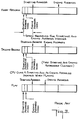
- the input signals are recorded for a fixed period of time, as determined by the time counter 200, and the output is recorded for the fixed period whether or not any input signals are received, as seen in Fig. 2.
- the portion A of the first message is recorded over by the second message C, but the portion B of the first message is not recorded over, and appears in the replay of the message.
- This arrangement has the disadvantage that noise is played upon replay. In addition, it does not replay correctly when the speaker speaks too slow and when a sentence has pauses. Further, the machine replays previous messages that were not recorded over, when the second message is shorter than the first.
- the previous message is replayed if a later recorded message is shorter than an earlier recorded message.
- the DRAM is first loaded with a message content "1 2 3 4 5 6 7 8 9 10 11 12 13 14 15 16 17 18 19 20”
- a later message only has the content "A B C D”
- the playback will contain the message "A B C D 5 6 7 8 9 10 11 12 13 14 15 16 17 18 19 20", even though it is desired to hear the message "A B C D - A B C D - A B C D - etc.”
- a central processing unit such as a micro-processor system, which includes the DRAM, controls the start and end of the recording and replay operations (as seen for example in Fig. 3).
- the start and end addresses of the DRAM are saved at a determined location in the DRAM, so that it is only necessary to record during times at which speech occurs.
- This arrangement has the disadvantage, however, that the system requires a CPU, complicated circuits are required, and some waste of the DRAM space occurs.
- US 4591929 discloses electronic recording apparatus to be used with a conventional tape recorder for learning a foreign language.
- the apparatus incorporates an electronic storage circuit for storing a signal to be recorded and start and end location addresses for the signal.
- the present invention is directed to the provision of a method and apparatus that overcomes the above disadvantages.
- an apparatus is provided as set out in claim 1 and a corresponding method as represented by claim 18. While recording, the user can enter contents with various time spans. During replay, the system automatically repeats the exact contents without any other background noise or noise speech at the end of the desired recorded message.
- the apparatus includes a wave clearer, a direct current voltage generator, a high frequency signal generator, a DC voltage detecting and time setting circuit, a resetter, and a recording and replay signal generator.
- a high frequency signal is used to record Low logic level speech codes to clear those original existing speech codes stored in DRAM. It is important that the Low level signal, as a DC signal, is mute and different from the phonetic codes of background noise. This is illustrated in Fig. 4.
- the Low level (DC voltage) acts as an index in place of the conventional technique wherein DRAM memory space is used to record the starting and ending addresses. Users can record speech signals of various length, and, during replay, the system replays from the start of the message whenever, during a replay process, a short continuous Low signal level is detected. There is no necessity in waiting until the whole memory is decoded, and any portion of the memory that has not been recorded over will not be replayed.
- a DC voltage is inserted at the end of the time that speech has been recorded. During replay, this voltage serves as a controlling signal for replay.
- the above two embodiments of the invention thus have different structures, but function in the same manner.
- the major difference between the present invention and conventional arrangements and methods is that the DC voltage and the background noise voltage are totally different.
- the present invention does not result in misplay due to misjudgment.
- conventional arrangements detect background noise and count the time with time setting circuits, so that the system replays when a certain time period of background noise is detected, as discussed above.
- the message content is thus in danger of being cut off if the speaker speaks slowly, or if he pauses in the process of recording. For example, if the speaker intends to count the sequence of number from 1 to 8, but pauses after the number 4, background noise will be recorded between the recording of the numbers 4 and 5.
- the background noise following the playback of the number 4 will effect the resetting of the address counter, so that the sequence 1 - 2 - 3 - 4 will be repeated, since conventional arrangements reset the address counter upon detection of background noise.
- the system of the invention permits such playback.
- the method and apparatus of the invention provides the optimum output, so that it is effective for repetitive public announcement systems, commercial selling announcements, telephone answering machines, and language learning recorders.
- People normally record for different time durations, while the DRAM has a fixed recording space, so that it is difficult for the speaker to time his speaking period to be the same as that of the recording.
- the conventional record and replay system either waits during blank periods, or replays an unintended message.
- the system replays only the desired speech signals since the DRAM is cleared by a Low level signal.
- the first embodiment using a high frequency signal, sets a DC voltage into its DRAM whenever original existing signals are erased and new speech signals are recorded.
- the second set of circuits records the speech signals in DRAM and inserts a DC voltage signal when the recording is finished. The system then automatically repeats the contents when the Play Button is depressed. Both sets of circuits use the recorded DC voltage signal, which is a mute signal, as an index for replay.
- the system of the invention includes a wave clearer 10, a DC voltage input setter 20, a high frequency signal generator 30, a resetter 40, a DC voltage detector and time setter 50 and a recording and replay wave generator 60. Suitable embodiments of these circuits will be described later with respect to Figs. 6-12, wherein these circuits are illustrated in greater detail.
- the circuit as illustrated in Fig. 5 further includes a DRAM and Speech Encoder/Decoder 100 of conventional construction.
- the address counter of the DRAM and Speech Encoder/Decoder 100 When the power is on, the address counter of the DRAM and Speech Encoder/Decoder 100 outputs a signal to the wave clearer 10, resulting in a Low output level signal from the wave clearer (see Fig. 6).
- the user depresses the Record Button 11 (Fig. 12), and, in response thereto, the recording and replay wave generator 60 outputs a Low WR/ (ie. active low Write) signal.
- the Low WR/ signal controls the DC voltage detector and time setter 50 so that the circuit stops counting time, i.e. the time setter 50 outputs a Low level signal when recording is in process.
- the WR/ signal also generates a pulse to send a High level signal input to the wave clearer 10.
- This High level signal also controls the high frequency signal generator 30 to send a normal high frequency wave to the Speech encoder/decoder.
- This High signal also controls the DC voltage input setter 20 to apply a DC voltage to the input of the Speech Encoder/Decoder.
- a DC (mute) voltage is set into all the DRAMs in high frequency at the same time, so the time required for clearing the DRAMs does not increase with the increase of the number of DRAMs used for previous recording.
- the address in address counter of the Speech Encoder/Decoder 100 is at the last stage and a High logic level signal is sent to the input of the wave clearer 10.
- the output of the wave clearer 10 changes from a High level to Low level.
- This Low level causes the DC voltage input circuit 20 to stop applying a DC voltage to the Speech Encoder/Decoder 100, and the high frequency signal generator 30 stops generating high frequency signals and to output speech codes at the normal recording frequency.
- Figs 6-11, 13, 14 and 16 illustrate circuit details for suitable circuits that may be employed in the disclosed arrangement of the invention. Since each of these circuits is illustrated employing conventional symbols, a detailed listing of the circuit connections will be omitted herein as superfluous, the following paragraphs explaining the operation of these circuits.
- the output of the wave clearer 10 is set to Low level by the address counter.
- the output becomes High when the Record Button is depressed. This High level is output to the DC voltage input circuit and to the High Frequency counter to effect clearing.
- the Address Counter applies a Low signal to the wave clearer again when the clearing process has been completed
- the DC voltage input circuit 20 is a switching circuit and is controlled by the wave clearer.
- the wave clearer When the Record Button is not depressed, the wave clearer outputs a Low level to the DC voltage input circuit, and the circuit is off.
- the wave clearer When the Record Button is depressed, the wave clearer outputs a High level to the DC voltage input circuit, and turns the input circuit on.
- the DC voltage input circuit will then output a DC voltage to the Speech Encode/Decode circuit to enable all of the DRAMs to be cleared.
- the high frequency signal generator 30 is comprised of a high frequency oscillating circuit.
- the circuit is controlled by the output of the wave clearer.
- the output of the wave clearer is at Low logic level, and the high frequency signal generator is controlled to generate "normal" frequency oscillations.
- the output of the wave generator is High, and the high frequency generator is controlled thereby to generate a high frequency oscillation for application to the address counter and the DRAM for the clear process.
- the resetter 40 provides a reset signal for the address counter, to reset the counter to the start of its memory.
- the resetter provides such an output under four conditions:
- the DC voltage detector and time setter 50 is comprised of a voltage comparator and a time counter. It is controlled by the recording and replay wave generator. In the Recording mode, the device will not function since the comparator works either during recording or during replay, but the time setting circuit works only when it is in the replay mode. Once the DC voltage sent from the DRAM lasts longer than the preset time period (user dependent), the device outputs a reset wave to the resetter.
- the record and replay wave generator 60 is controlled by the Record Button and the external recording and replay input. When neither of the controllers output a signal, the WR/ output of the record and replay wave generator is at High logic level. The system is then in the replay mode. When the Record Button is depressed or when the external recording and replay input is at a Low level, the WR/ output of the record and replay wave generator becomes Low and the circuit generates a reset signal for the resetter and the clearing of the DRAM starts. When the external selection inputs a Low level, the end signal of the address counter does not change the WR/ output of the record and replay wave generator, i.e. when the Record Button is depressed, new speech content will be recorded.
- the end signal of the address counter will change the WR/ output of the record and replay wave generator. Even if the Record Button is still depressed, an end signal will be sent to change the WR/ output of the record and replay wave generator to a High level after the counter records for one cycle. That is, the system replays automatically after one DRAM cycle is completed.
- a reset wave is generated when the Record Button is released or when the external selection input goes to a High level and the system starts to replay.
- FIG. 15 The second embodiment of the invention is illustrated in the block diagram of Fig. 15. This arrangement is comprised of a DC input generator 20 (see Fig. 7), a resetter 40 (see Fig. 9) a DC voltage detector and time setter 50 (see Fig. 10) and a recording and replay wave generator (see Fig. 16).
- Fig. 17 shows this arrangement in greater detail.
- Fig. 15 does not employ a wave clearer to clear the memory, the user just depresses the Record Button 11 while recording.
- the Speech Encoder/Decoder and DRAM replay under all of these three conditions,.
- the user does not have to touch the Play Button 12 again in order to replay the content one more time.
- the system will not replay all the blank space in DRAM, it replays the recorded content only. If a user wants to hear the beginning or the content in the middle of the replay process, he just depresses the Play Button.
- circuits of the invention are easy to fabricate, clear in logic, and, what is more important, useful. They do not employ a CPU, and starting and ending address indexes are not stored in DRAM. This invention does not require the use of complicated expensive circuits.
- the circuits shown herein are only exemplary, and other equivalent circuits may be employed within the scope of the invention. For example only, there are suitable circuits for the high frequency oscillator that do not require the use of an inverter.
- Pulse generators that may substitute for those shown in Fig. 13 can be formed by the use of flip-flops or other devices.
- a transmission gate, such as shown in Fig. 7, can be replaced by a suitable transistor or other device.
- the function of the recording and replay wave generator can be extended by adding an external recording and replay input.
- a Low level signal is sent by the Record Button when clearing and recording.
- a High level signal is given when the Record Button is released, and the system replays from the beginning.
- the system may employ a combined Play Button and Record Button, as illustrated in Fig. 14B. Suitable resistors and capacitors are provided for these buttons in accordance with conventional design.
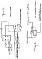
- Fig. 18 is a block diagram of a speech encoder-decoder and DRAM circuit for connection to the circuit of Fig. 12.
- the interconnections A-I illustrated on this diagram correspond to the interconnections A-I of Fig. 12.
- the DRAM in this circuit may by conventional DRAM, for example of type TMS4256.
- the signal on the WR/ line F goes from a high level to a low level, and the device is thereby placed in the recording mode.
- the low level WR/ signal stops the DC voltage Detector and Time Setter 50 from outputting any signals.
- a low level WR/ signal also makes the Recording and Playing Wave Generator 60 generate a one-shot pulse on line 400.
- This pulse on line 400 is applied to the Resetter 40 and enables the Resetter 40 to output a high level signal on line E.
- the signal on line E is applied to the Address Counter 199 (Fig. 18) to reset the DRAM 101 address to the initial address.
- the pulse on line 400 also makes the Wave Clearer 10 generate a high level signal on line B.
- the system When the wave clearer 10 is off, the system is in normal recording mode. In this mode, speech signals are conveyed from the Analog Input (MIC) (Fig. 18) to the CVSD encoder/decoder comprised of the preamplifier 104, comparator 105, shift register 106, slope detector 110, voltage to current converter 111, polarity control 112, and integrator 113.
- the speech signal is first amplified by the preamplifier 104, and then compared with 1/2 V DD .
- the output of the preamplifier is higher than 1/2 V DD , the output of the comparator 105 is low.
- the signal DI sampled at the first stage of the shift register 106, is stored in the 256K DRAM.
- the signal DI controls the polarity control circuit 112 and the V/I converter 11 to control the integrator to perform positive integration so that the output signal of the integrator on line G will more closely follow the speech signal waveform.
- the slope detector 110 controls the V/I converter 111 to amplify the integration current so that the output signal of the integrator on line G approaches the speech signals more quickly.
- DI is sampled at the first stage of the shift register 106 and is stored in the 256K DRAM.
- DI controls the polarity control circuit 112 and V/I converter 111 so that the integrator 113 performs negative integration and the output signal of the integrator on line G is decreased and more similar to the speech waveform.
- the slope detector 110 controls the V/I converter 111 to amplify the integration current so that the output signal of the integrator on line G approaches the speech signal waveform more quickly. The encoding of the speech signals is then completed.
- the WR/ signal on line F changes to a high level, and the DC voltage detector and time setter 50 starts detecting the DC voltage.
- the message D0 saved in the 256K DRAM is then applied to the shift register 106 directly via line 52, and the shift register 106 applies the signal D0 to the Polarity Control 112 and V/I converter 111 to let the output of the integrator on line G start integration from 1/2 V DD .
- the integrator When D0 has a low level, the integrator performs positive integration to amplify the signal on line G. When D0 has a high level, the integrator performs negative integration to decrease the signal on line G. When three Do signals having the same level are output, the slope detector 110 controls the integration current to amplify the V/I converter current. The decoding of the speech signals is then completed. At this time, control SW51 sends the output signal of the integrator on line G to the filter, power amplifier and speaker, to start the replay operation.
- the DC voltage detector and Time setter 50 detects this zero level (mute), and generates a one-shot pulse on line 600 (Fig. 12) for application to the resetter 40.
- This pulse on line 600 enables the resetter 40 to output signal a signal on line E to the Address Counter 101 to reset the address to the initial address so that the device replays from the beginning.
- a speech encoder/decoder and DRAM circuit for use in combination with the circuit of Fig. 17 is similar to that illustrated in Fig. 18, differing therefrom only in the omission of the use of the signal B for controlling the CAS/,RAS/ generator 102, the provision of a separate oscillator (not illustrated) as a source of oscillations for the CAS/,RAS/ generator 102, and the omission of the signal D.
- the lines identified in Fig. 17 are adapted to be connected to similarly identified lines in Fig. 18.
- the Recording and Playing Wave Generator 90 outputs a one-shot pulse on line 800 to change the WR/ signal on line F to a high level, after a short delay.
- the system is then in the replay mode.
- the pulse on line 800 is applied to the DC voltage input circuit 20 to let the output voltage thereof on line C be applied to the preamplifier 104 of the continuous variable slope delta (CVSD) encoder/decoder of Fig. 18.
- the DC voltage on the line C holds the output of the preamplifier at a zero level (mute) during the above noted time delay.
- the mute signal is applied to the CVSD encoder/decoder and then saved in the 256K DRAM 101.
- the DC voltage detector and Time Setter 50 detects the mute signal, and then sends a pulse signal on line 600 to the resetter for generating a signal on line E. This signal resets the address counter to its initial address.
- the two above described embodiments of the invention thus effect automatic address setting the recording and playback of speech.
- the system can work with the use of memory or a CPU for controlling the address index.
Landscapes
- Engineering & Computer Science (AREA)
- Microelectronics & Electronic Packaging (AREA)
- General Physics & Mathematics (AREA)
- Physics & Mathematics (AREA)
- Theoretical Computer Science (AREA)
- Educational Administration (AREA)
- Educational Technology (AREA)
- Business, Economics & Management (AREA)
- Television Signal Processing For Recording (AREA)
- Indexing, Searching, Synchronizing, And The Amount Of Synchronization Travel Of Record Carriers (AREA)
- Pens And Brushes (AREA)
- Management Or Editing Of Information On Record Carriers (AREA)
- Input Circuits Of Receivers And Coupling Of Receivers And Audio Equipment (AREA)
- Signal Processing Not Specific To The Method Of Recording And Reproducing (AREA)
Abstract
Description
- This invention relates to a method and apparatus for the automatic address setting for speech recording and replay.
- The invention can be employed in various applications, such as toys, recursive public announcement systems, commercial selling announcements, telephone answering machines, language learning recorders, and other arrangements which require different recording time durations and wherein the recorded contents can be frequently renewed and replayed. The invention is of course not limit to these specified applications.
- DRAM has been commonly employed recently in various devices such as toys, language learning recorders, and telephone answering machines. Usually such devices have fixed time periods for recording and replay. The memory records background noise if the speaker enters a message that is shorter than the preset time period. Even a speaker-time-dependent recorder retains the part of the previous recorded message that was not recorded over when a latter message happens to be shorter than the previous one.
- In accordance with two conventional techniques:
- 1. The machine replays automatically after a certain length of background noise is detected. Such a circuit structure is illustrated in Fig. 1. In this arrangement, the input signals are recorded for a fixed period of time, as determined by the time counter 200, and the output is recorded for the fixed period whether or not any input signals are received, as seen in Fig. 2. Thus, the portion A of the first message is recorded over by the second message C, but the portion B of the first message is not recorded over, and appears in the replay of the message. This arrangement has the disadvantage that noise is played upon replay. In addition, it does not replay correctly when the speaker speaks too slow and when a sentence has pauses. Further, the machine replays previous messages that were not recorded over, when the second message is shorter than the first.
- Thus, in this type of device, since the memory is not cleared before a second recording, the previous message is replayed if a later recorded message is shorter than an earlier recorded message. For example, if the DRAM is first loaded with a message content "1 2 3 4 5 6 7 8 9 10 11 12 13 14 15 16 17 18 19 20", and a later message only has the content "A B C D", the playback will contain the message "A B C D 5 6 7 8 9 10 11 12 13 14 15 16 17 18 19 20", even though it is desired to hear the message "A B C D - A B C D - A B C D - etc."
- 2. In the second conventional arrangement, a central processing unit (CPU), such as a micro-processor system, which includes the DRAM, controls the start and end of the recording and replay operations (as seen for example in Fig. 3). The start and end addresses of the DRAM are saved at a determined location in the DRAM, so that it is only necessary to record during times at which speech occurs. This arrangement has the disadvantage, however, that the system requires a CPU, complicated circuits are required, and some waste of the DRAM space occurs.
- US 4591929 discloses electronic recording apparatus to be used with a conventional tape recorder for learning a foreign language. The apparatus incorporates an electronic storage circuit for storing a signal to be recorded and start and end location addresses for the signal.
- Known systems have the following disadvantages:
- 1. The system may replay incorrectly when the speaker speaks too slowly or when there is a pause in a sentence.
- 2. DRAM may be required to store the start and stop addresses.
- 3. The circuit structure may be complicated if a CPU is required.
- 4. The time required to clear the DRAM is increased as an increasing number of DRAM circuits are required for recording.
- The present invention is directed to the provision of a method and apparatus that overcomes the above disadvantages.
- In accordance with the invention, an apparatus is provided as set out in
claim 1 and a corresponding method as represented by claim 18. While recording, the user can enter contents with various time spans. During replay, the system automatically repeats the exact contents without any other background noise or noise speech at the end of the desired recorded message. The apparatus includes a wave clearer, a direct current voltage generator, a high frequency signal generator, a DC voltage detecting and time setting circuit, a resetter, and a recording and replay signal generator. - In accordance with the first embodiment of the invention. A high frequency signal is used to record Low logic level speech codes to clear those original existing speech codes stored in DRAM. It is important that the Low level signal, as a DC signal, is mute and different from the phonetic codes of background noise. This is illustrated in Fig. 4. The Low level (DC voltage) acts as an index in place of the conventional technique wherein DRAM memory space is used to record the starting and ending addresses. Users can record speech signals of various length, and, during replay, the system replays from the start of the message whenever, during a replay process, a short continuous Low signal level is detected. There is no necessity in waiting until the whole memory is decoded, and any portion of the memory that has not been recorded over will not be replayed.
- In accordance with a second embodiment of the invention, a DC voltage is inserted at the end of the time that speech has been recorded. During replay, this voltage serves as a controlling signal for replay.
- The above two embodiments of the invention thus have different structures, but function in the same manner. The major difference between the present invention and conventional arrangements and methods is that the DC voltage and the background noise voltage are totally different. The present invention does not result in misplay due to misjudgment. Thus, conventional arrangements detect background noise and count the time with time setting circuits, so that the system replays when a certain time period of background noise is detected, as discussed above. In conventional arrangements, the message content is thus in danger of being cut off if the speaker speaks slowly, or if he pauses in the process of recording. For example, if the speaker intends to count the sequence of number from 1 to 8, but pauses after the
number 4, background noise will be recorded between the recording of thenumbers 4 and 5. Upon replay, the background noise following the playback of thenumber 4 will effect the resetting of the address counter, so that the sequence 1 - 2 - 3 - 4 will be repeated, since conventional arrangements reset the address counter upon detection of background noise. - However, if it is desired to hear the background noise between the playback of the
numbers 4 and 5 , the system of the invention permits such playback. - The method and apparatus of the invention provides the optimum output, so that it is effective for repetitive public announcement systems, commercial selling announcements, telephone answering machines, and language learning recorders. People normally record for different time durations, while the DRAM has a fixed recording space, so that it is difficult for the speaker to time his speaking period to be the same as that of the recording. In the absence of the system of the invention, the conventional record and replay system either waits during blank periods, or replays an unintended message. In the arrangement of the present invention, however, the system replays only the desired speech signals since the DRAM is cleared by a Low level signal.
- In order that the invention may be more clearly understood, it will now be disclosed in greater detail with reference to the accompanying drawing, wherein:
- Fig. 1 is a block diagram of a conventional system;
- Fig. 2 is a timing diagram illustrating the operation of the system of Fig. 1;
- Fig. 3 is a timing diagram illustrating the operation of another known system;
- Figs. 4A and 4B are timing diagrams illustrating the operation of the present invention
- Fig. 5 is a block diagram of a first embodiment of the invention;
- Fig. 6 is a block diagram of a wave clearer for use in the system of Fig. 5;
- Fig. 7 is a block diagram of a voltage input circuit for use in the system of Fig. 5;
- Fig. 8 is a block diagram of a high frequency signal generator for use in the system of Fig. 5;
- Fig. 9 is a block diagram of a resetter for use in the system of Fig. 5;
- Fig. 10 is a block diagram of a time setter for use in the system of Fig. 5;
- Fig. 11 is a block diagram of a recording replay wave generator for use in the system of Fig. 5;
- Fig. 12 is a more complete block diagram of the first embodiment of the invention;
- Figs. 13A and 13B are block diagrams of pulse generators for use in the systems of Figs. 5 and 12;
- Figs. 14A and 14B are block diagrams of circuits for the Record and Play Buttons for use in the systems of Figs. 5 and 12;
- Fig. 15 is a block diagram of a second embodiment of the invention
- Fig. 16 is a block diagram of a recording and replay circuit generator for use in the system of Fig. 15;
- Fig. 17 is a block diagram of a more detailed structure of the system of Fig. 15; and
- Fig. 18 is a block diagram of a speech encoder-decoder and DRAM circuit for use with the system of Fig. 12.
- Two preferred embodiments of the invention will be discussed hereinafter. The first embodiment, using a high frequency signal, sets a DC voltage into its DRAM whenever original existing signals are erased and new speech signals are recorded. During recording, the user can record speech with various time spans and the system automatically repeats the contents during replay. The second set of circuits records the speech signals in DRAM and inserts a DC voltage signal when the recording is finished. The system then automatically repeats the contents when the Play Button is depressed. Both sets of circuits use the recorded DC voltage signal, which is a mute signal, as an index for replay.
- Referring now to the drawings, and more in particular to Figs. 5-12, therein is illustrated a system in accordance with the first embodiment of the invention.
- As illustrated in Fig. 5, the system of the invention includes a wave clearer 10, a DC
voltage input setter 20, a highfrequency signal generator 30, aresetter 40, a DC voltage detector andtime setter 50 and a recording andreplay wave generator 60. Suitable embodiments of these circuits will be described later with respect to Figs. 6-12, wherein these circuits are illustrated in greater detail. The circuit as illustrated in Fig. 5 further includes a DRAM and Speech Encoder/Decoder 100 of conventional construction. - When the power is on, the address counter of the DRAM and Speech Encoder/
Decoder 100 outputs a signal to the wave clearer 10, resulting in a Low output level signal from the wave clearer (see Fig. 6). During recording, the user depresses the Record Button 11 (Fig. 12), and, in response thereto, the recording andreplay wave generator 60 outputs a Low WR/ (ie. active low Write) signal. This causes the Speech Encoder/Decoder to start recording the message in the DRAM. At the same time, the Low WR/ signal controls the DC voltage detector andtime setter 50 so that the circuit stops counting time, i.e. thetime setter 50 outputs a Low level signal when recording is in process. The WR/ signal also generates a pulse to send a High level signal input to thewave clearer 10. This High level signal also controls the highfrequency signal generator 30 to send a normal high frequency wave to the Speech encoder/decoder. This High signal also controls the DCvoltage input setter 20 to apply a DC voltage to the input of the Speech Encoder/Decoder. A DC (mute) voltage is set into all the DRAMs in high frequency at the same time, so the time required for clearing the DRAMs does not increase with the increase of the number of DRAMs used for previous recording. When all memories are full, the address in address counter of the Speech Encoder/Decoder 100 is at the last stage and a High logic level signal is sent to the input of thewave clearer 10. In response thereto, the output of the wave clearer 10 changes from a High level to Low level. This Low level causes the DCvoltage input circuit 20 to stop applying a DC voltage to the Speech Encoder/Decoder 100, and the highfrequency signal generator 30 stops generating high frequency signals and to output speech codes at the normal recording frequency. - The whole clearing process takes approximately 0.5 second, that is to say, the
wave clearer 1 generates a High level output lasting for 0.5 second. This High logic level signal thus: - causes the generation of high frequency signals to send a high frequency wave to the Speech Encoder/Decoder;
- enables the DC
voltage input setter 20 to generate a DC voltage for application to the Speech Encoder/Decoder; - causes the clearing of all of the DRAMs at the same time; and
- causes the controlling of any LED display or time signals in the process of clearing.
- After this 0.5 second clearing step, the wave clearer 10 resumes its Low level output, and:
- the high frequency signal generator is caused to stop generating a high frequency signal;
- the DC
voltage input setter 20 is controlled to stop operating; - the clearing of the DRAMs is stopped;
- the clearing process ends, and
- the speech signals start being saved in the Speech Encoder/Decoder and
DRAM system 100. - A. When the
external selection key 65 is controlled to apply a High logic level output to the circuit:- a). If the speaker keeps depressing the
Record Button 11 when all the DRAMs are filled, the address counter in the Speech Encoder/Decoder 100, after finishing one DRAM cycle, generates a High logic level output. This High output controls the record andreplay wave generator 60 to change its output from a Low level to a High level, and the decoding (replay) starts. A complete cycle is replayed after theRecord Button 11 is depressed - b). In a second situation that may occur, the speaker releases the
Record Button 11 before the DRAMS are full and the signal input to the circuit from the Record Button to the circuit changes from a Low level to a High level. This High level signal then controls the recording andreplay wave generator 60 to output a High level signal, to start the decoding (replay).
- a). If the speaker keeps depressing the
- B. When the
external selection key 65 is set to apply a Low logic level to the circuit:- a). If the speaker keeps pressing the
Record Button 11 when the DRAMs are full, the Speech Encoder/ decoder will continue to record new speech signals. The address counter will not generate a High output after finishing one DRAM cycle, so the recording andreplay wave generator 60 will not effect a decoding (replay) process. The system starts decoding (replay) only when the speaker releases the Record Button. It replays the last complete DRAM cycle recorded before the Record Button is released. - b). Like the above discussed condition b) when the external selection key is set to a High level, the record signal changes from a Low level to a High level when the speaker releases the Record Button before the DRAMs are full. The recording and
replay wave generator 60 starts decoding (replay) when this High (DC) signal is detected.
- a). If the speaker keeps pressing the
- There are three different situations that may occur in the above recording and replay:
- If the speaker keeps pressing the Record Button when the DRAMs finish running one cycle, the system replays automatically.
- If the speaker keeps pressing the Record Button when the DRAMs finish running one cycle, the DRAMs keep recording a new input message. The system replays only when the Record Button is released and it replays the contents recorded in the last cycle.
- If the speaker releases the Record Button before one DRAM cycle is completed, the system replays the recorded message content.
- i). Under the first condition, when the external selection input is set to a High level, the address counter in the Speech Encoder/Decoder applies a High level signal to the recording and
replay wave generator 60 when the DRAMs are filled with an input message. The recording and replay wave generator thus changes its WR/ output from a Low level to a High level. A pulse generated thereby is sent to theresetter 4 and to the speech encoder decoder to reset the address counter. The High WR/ output of the recording andreplay wave generator 60 controls the DC voltage detecting and thetime setting circuit 50 to start detecting the DC voltage and time counting. The process is still controlled by the DC voltage comparator. During the DRAM speech signal decoding (replay) process, the DC voltage comparator keeps outputting a High level signal volt which keeps thetime setter 50 on a reset mode (stop counting). The DC voltage detector andtime setter 50 do not function because all the DRAMs are full, there is no blank DC voltage after decoding, and the comparator outputs a High level. - ii) The second condition is the same as the first except that when the external selection input is set at a Low level, the recording and
replay wave generator 60 will not generate a High WR/ output when the DRAMs are full. The system does not replay until the Record Button is released. A pulse will not be sent to theresetter 4 to reset the address counter, and it continues to record a new message. When the speaker releases the Record Button, a complete DRAM cycle of content will be replayed. - iii) The third condition is that the Record Button is released before the DRAMs are full. Independently of the setting of the
external selection key 65, the recording andreplay wave generator 60 generates a High WR/ output which controls the DC voltage detection andtime setting circuit 50 to detect a DC voltage and start time counting. After a determined time period is counted a reset wave will be sent to the address counter. The address counter starts from the beginning, namely, the DRAM is decoded from the beginning. The decoded content can be replayed repetitively and only pauses shorter than 0.5 second will be replayed. During decoding (replay), a DC (mute) voltage is detected whenever there are pauses. It is different from a background noise which gives alternating current voltage noise signals carried on 1/2 Vcc. The comparator 5 can easily distinguish the signals and control thetime counter 50 to count only when DC voltage exists.
- i). Under the first condition, when the external selection input is set to a High level, the address counter in the Speech Encoder/Decoder applies a High level signal to the recording and
- All of the three situations enable the speech decoder and DRAM to replay. The user does not have to touch the
Play Button 12 again in order to replay the message content again. The system will not replay all the blank space in DRAM, it replays the recorded message content only. If a user wants to listen the beginning of the message content in the middle of the replay process, he just pushes thePlay Button 12. - Figs 6-11, 13, 14 and 16 illustrate circuit details for suitable circuits that may be employed in the disclosed arrangement of the invention. Since each of these circuits is illustrated employing conventional symbols, a detailed listing of the circuit connections will be omitted herein as superfluous, the following paragraphs explaining the operation of these circuits.
- The Wave clearer illustrated in Fig. 6:
- When the power is on, the output of the wave clearer 10 is set to Low level by the address counter. The output becomes High when the Record Button is depressed. This High level is output to the DC voltage input circuit and to the High Frequency counter to effect clearing. The Address Counter applies a Low signal to the wave clearer again when the clearing process has been completed
- The DC Voltage input circuit illustrated in Fig. 7:
- The DC
voltage input circuit 20 is a switching circuit and is controlled by the wave clearer. When the Record Button is not depressed, the wave clearer outputs a Low level to the DC voltage input circuit, and the circuit is off. When the Record Button is depressed, the wave clearer outputs a High level to the DC voltage input circuit, and turns the input circuit on. The DC voltage input circuit will then output a DC voltage to the Speech Encode/Decode circuit to enable all of the DRAMs to be cleared. - The high frequency signal generator of Fig. 8:
- The high
frequency signal generator 30 is comprised of a high frequency oscillating circuit. The circuit is controlled by the output of the wave clearer. When the Record Button is not pushed, the output of the wave clearer is at Low logic level, and the high frequency signal generator is controlled to generate "normal" frequency oscillations. When the Record Button is depressed, the output of the wave generator is High, and the high frequency generator is controlled thereby to generate a high frequency oscillation for application to the address counter and the DRAM for the clear process. - The resetter of Fig. 9:
- The
resetter 40 provides a reset signal for the address counter, to reset the counter to the start of its memory. The resetter provides such an output under four conditions: - 1. When the Record Button is depressed and a clearing process starts;
- 2. When the Play Button is depressed and replay starts;
- 3. When recording is over;
- 4. When the DC voltage detecting and time setting circuit finishes processing.
- The DC voltage detector and time setter of Fig. 10:
- The DC voltage detector and
time setter 50 is comprised of a voltage comparator and a time counter. It is controlled by the recording and replay wave generator. In the Recording mode, the device will not function since the comparator works either during recording or during replay, but the time setting circuit works only when it is in the replay mode. Once the DC voltage sent from the DRAM lasts longer than the preset time period (user dependent), the device outputs a reset wave to the resetter. - The recording and replay wave generator of Fig. 11:
- The record and
replay wave generator 60 is controlled by the Record Button and the external recording and replay input. When neither of the controllers output a signal, the WR/ output of the record and replay wave generator is at High logic level. The system is then in the replay mode. When the Record Button is depressed or when the external recording and replay input is at a Low level, the WR/ output of the record and replay wave generator becomes Low and the circuit generates a reset signal for the resetter and the clearing of the DRAM starts. When the external selection inputs a Low level, the end signal of the address counter does not change the WR/ output of the record and replay wave generator, i.e. when the Record Button is depressed, new speech content will be recorded. When the external selection inputs a High level, the end signal of the address counter will change the WR/ output of the record and replay wave generator. Even if the Record Button is still depressed, an end signal will be sent to change the WR/ output of the record and replay wave generator to a High level after the counter records for one cycle. That is, the system replays automatically after one DRAM cycle is completed. A reset wave is generated when the Record Button is released or when the external selection input goes to a High level and the system starts to replay. - The pulse generators of Fig. 13:
- These are conventional pulse generation circuits.
- The recording and replay button circuits of Fig. 14:
- These circuits show variations of the connections of switches for achieving the functions of the Play Button and Record Button.
- (II) The second embodiment of the invention is illustrated in the block diagram of Fig. 15. This arrangement is comprised of a DC input generator 20 (see Fig. 7), a resetter 40 (see Fig. 9) a DC voltage detector and time setter 50 (see Fig. 10) and a recording and replay wave generator (see Fig. 16). Fig. 17 shows this arrangement in greater detail.
- The arrangement of Fig. 15 does not employ a wave clearer to clear the memory, the user just depresses the
Record Button 11 while recording. - A. When the
external selection key 65 is set to apply a High logic level to the system (Fig. 17)- a. If the speaker keeps depressing the
Record Button 11 after the DRAMs are full, the address counter in the Speech Encoder/Decoder 100, after counting one cycle, generates a High output to cause the recording and replay generator to generate a High WR/ output which enables decoding (replay). Namely, the system replays automatically after recording for one DRAM cycle. - b) If the speaker releases the
Record Button 11 before the DRAMs are full, the voltage applied by the Record Button is temporarily held. During this delay the voltage controls the DCvoltage input generator 20 to generate a DC voltage for application to the Speech Encoder/Decoder and DRAM. The system starts replaying after this delay. Whenever theDC voltage detector 50 detects the finish count of DC voltage, it starts from the beginning and replays the recorded content all over again.
- a. If the speaker keeps depressing the
- B. When the external selection key is set to Low:
- a) If the speaker keeps depressing the
Record Button 11 when the DRAMs are full, the Speech Encoder/Decoder 100 keeps recording new speech signals. The address counter of the Speech Encoder/Decoder will not generate a High output after finishing one cycle, so the recording and replay wave generator will not assume the decoding (replay) process. It starts decoding (replay) when the Record Button is released. The decoding (replay) operation will last for one complete cycle because the starting address of replay is exactly the same as the ending address of recording. (The address counter is not reset process when the replay starts. It replays from the ending address of the recording.) - b). If the speaker releases the Record Button before the DRAMs are full, there will be a delay in the occurrence of the record voltage. The DC
voltage input circuit 20 generates a DC voltage during this delay and the system starts to replay after the delay. The system is reset and replays from the beginning because the address counter of the Speech Encoder/Decoder 100 is reset. The DC voltage detector resets the address counter and the system replays from the beginning, when a predetermined duration DC voltage is detected.
- a) If the speaker keeps depressing the
- There are three different conditions in the recording and replay of this second embodiment of the circuit:
- If the Record Button continues to be depressed after recording for one cycle, the system replays automatically;
- If the Record Button continues to be depressed after recording for one cycle, the system keeps recording new speech signals instead of replaying. It replays only when the Record Button is released and replays the message recorded in the last DRAM cycle before the recording ends.
- If the Record Button is released before one DRAM cycle ends, a DC voltage for record delay is output and the system replays automatically after the delay.
- i) In the first condition, when the external selection key is set on the High level mode, the address counter in the Speech Encoder/Decoder generates a High level signal for application to the recording and
replay wave generator 90 and causes the WR/ output to be High with the DRAMs full. As the WR/ output changes from Low to High, a pulse is sent to the resetter and to the Speech Encoder/Decoder to reset the address counter. The High WR/ output from the recording andreplay wave generator 90 also enables the DC voltage detecting and time setting circuit to start detecting the DC voltage and time counting. It is also controlled by the output from the DC voltage comparator. The DC voltage detecting comparator keeps outputting the High signal level in the DRAM decoding process. The High voltage keeps the time counter in a reset mode (counting stopped). The DC voltage detector and time setter does not have to function because the DRAMs are full and there is no blank DC voltage after decoding, the comparator output remains at a High level. - ii) The second condition is the same as the first except that the external selection key is set to a Low level. The recording and replay wave generator will not generate a High WR/ output when the DRAMs are full. The system does not replay until the Record Button is released. A pulse will not be sent to the resetter to reset the address counter in the Speech Encoder/Decoder. Thus, when the recording finishes, the system replays a complete cycle of recorded messages starting from the point where the recording ends.
- iii) In the third condition the Record Button is released before the DRAMs are full. Independently of the setting of the
external selection key 65, there will be a record delay. The DC voltage input circuit generates a DC voltage for application to the DRAM during this delay and the system replays after this delay. The DC voltage detecting andtime setting circuit 50 now generates a reset signal for application to the address counter in the Speech Encoder/Decoder. The address counter starts counting, namely, the memory is read from the beginning to enable decoding. The recorded message content will be replayed while the extra message in DRAM will not be replayed except the blanks set to control the address counter.
- i) In the first condition, when the external selection key is set on the High level mode, the address counter in the Speech Encoder/Decoder generates a High level signal for application to the recording and
- The Speech Encoder/Decoder and DRAM replay under all of these three conditions,. The user does not have to touch the
Play Button 12 again in order to replay the content one more time. The system will not replay all the blank space in DRAM, it replays the recorded content only. If a user wants to hear the beginning or the content in the middle of the replay process, he just depresses the Play Button. - Detailed circuit structures of the embodiment of Fig. 12 are shown in Fig. 17. The circuits of the invention are easy to fabricate, clear in logic, and, what is more important, useful. They do not employ a CPU, and starting and ending address indexes are not stored in DRAM. This invention does not require the use of complicated expensive circuits. The circuits shown herein are only exemplary, and other equivalent circuits may be employed within the scope of the invention. For example only, there are suitable circuits for the high frequency oscillator that do not require the use of an inverter. Pulse generators that may substitute for those shown in Fig. 13 can be formed by the use of flip-flops or other devices. A transmission gate, such as shown in Fig. 7, can be replaced by a suitable transistor or other device.
- The function of the recording and replay wave generator can be extended by adding an external recording and replay input. A Low level signal is sent by the Record Button when clearing and recording. A High level signal is given when the Record Button is released, and the system replays from the beginning.
- The system may employ a combined Play Button and Record Button, as illustrated in Fig. 14B. Suitable resistors and capacitors are provided for these buttons in accordance with conventional design.
- Fig. 18 is a block diagram of a speech encoder-decoder and DRAM circuit for connection to the circuit of Fig. 12. The interconnections A-I illustrated on this diagram correspond to the interconnections A-I of Fig. 12. The DRAM in this circuit may by conventional DRAM, for example of type TMS4256.
- In the operation of the system of the invention, during recording, when the user pushes the record button 11 (Fig. 12), the signal on the WR/ line F goes from a high level to a low level, and the device is thereby placed in the recording mode. The low level WR/ signal stops the DC voltage Detector and
Time Setter 50 from outputting any signals. A low level WR/ signal also makes the Recording and PlayingWave Generator 60 generate a one-shot pulse online 400. This pulse online 400 is applied to theResetter 40 and enables theResetter 40 to output a high level signal on line E. The signal on line E is applied to the Address Counter 199 (Fig. 18) to reset theDRAM 101 address to the initial address. The pulse online 400 also makes theWave Clearer 10 generate a high level signal on line B. The high level signal on line B: - 1. Controls the high
frequency signal generator 30 to generate a high frequency signal on line A for application to the CAS/, RAS/generator 102 andAddress Counter 199 for generating CAS/, RAS/ signals and addresses A0-A8 for the 256K DRAM for high speed clearing of the DRAM. - 2. Enables the DC
Voltage Input circuit 20 to output a 0.5 second DC voltage on line C for application to thepreamplifier 104 of the Speech Encoder/Decoder of Fig. 18. The voltage on line C causes the output of the preamplifier to be held at zero voltage (mute) during the 0.5 second high speed clearing. This zero voltage signal is sampled by thecomparator 105 andshift register 106 and makes the first stage of the shift register output a 0.5 second Mute signal DI. The signal DI is applied to the256K DRAM 101 and clears all previous data in the DRAM. After the previously stored data has been cleared, the last address A8 of theAddress Counter 199 outputs a signal on line D to shut the Wave Clearer 10 off. The signal on line B is now set to a low level, and the clearing operation is stopped. - 3. Controls the CAS/, RAS/
generator 102 to let all DRAMs receive the CAS/ and RAS/ signals so that all DRAMs finish clearing at the same time. - When the wave clearer 10 is off, the system is in normal recording mode. In this mode, speech signals are conveyed from the Analog Input (MIC) (Fig. 18) to the CVSD encoder/decoder comprised of the
preamplifier 104,comparator 105,shift register 106,slope detector 110, voltage to current converter 111,polarity control 112, andintegrator 113. The speech signal is first amplified by thepreamplifier 104, and then compared with 1/2 VDD. - If the output of the preamplifier is higher than 1/2 VDD, the output of the
comparator 105 is low. The signal DI, sampled at the first stage of theshift register 106, is stored in the 256K DRAM. At the same time, the signal DI controls thepolarity control circuit 112 and the V/I converter 11 to control the integrator to perform positive integration so that the output signal of the integrator on line G will more closely follow the speech signal waveform. When theshift register 106 samples three successive low level signals, theslope detector 110 controls the V/I converter 111 to amplify the integration current so that the output signal of the integrator on line G approaches the speech signals more quickly. - If the output of the
preamplifier 104 is lower than 1/2 VDD, the output of thecomparator 105 will be high. DI is sampled at the first stage of theshift register 106 and is stored in the 256K DRAM. At the same time, DI controls thepolarity control circuit 112 and V/I converter 111 so that theintegrator 113 performs negative integration and the output signal of the integrator on line G is decreased and more similar to the speech waveform. When the shift register samples three successive high level signals, theslope detector 110 controls the V/I converter 111 to amplify the integration current so that the output signal of the integrator on line G approaches the speech signal waveform more quickly. The encoding of the speech signals is then completed. - Upon releasing the Record Button, the WR/ signal on line F changes to a high level, and the DC voltage detector and
time setter 50 starts detecting the DC voltage. The message D0 saved in the 256K DRAM is then applied to theshift register 106 directly vialine 52, and theshift register 106 applies the signal D0 to thePolarity Control 112 and V/I converter 111 to let the output of the integrator on line G start integration from 1/2 VDD. - When D0 has a low level, the integrator performs positive integration to amplify the signal on line G. When D0 has a high level, the integrator performs negative integration to decrease the signal on line G. When three Do signals having the same level are output, the
slope detector 110 controls the integration current to amplify the V/I converter current. The decoding of the speech signals is then completed. At this time, control SW51 sends the output signal of the integrator on line G to the filter, power amplifier and speaker, to start the replay operation. - During the replay process, if the output signal on line G has a continuous period of zero level (mute), i.e. the mute previously saved in the high speed, the DC voltage detector and
Time setter 50 detects this zero level (mute), and generates a one-shot pulse on line 600 (Fig. 12) for application to theresetter 40. This pulse online 600 enables theresetter 40 to output signal a signal on line E to theAddress Counter 101 to reset the address to the initial address so that the device replays from the beginning. - A speech encoder/decoder and DRAM circuit for use in combination with the circuit of Fig. 17 is similar to that illustrated in Fig. 18, differing therefrom only in the omission of the use of the signal B for controlling the CAS/,RAS/
generator 102, the provision of a separate oscillator (not illustrated) as a source of oscillations for the CAS/,RAS/generator 102, and the omission of the signal D. The lines identified in Fig. 17 are adapted to be connected to similarly identified lines in Fig. 18. - In use of the circuit of Fig. 17, when connected to the circuit of Fig. 18 as modified in the above manner, during recording the user depresses the Record Button. Speech signals then enter via the analog input MIC and the system starts saving the message D1 in the 256K DRAM. When the user releases the Record Button, the Recording and Playing
Wave Generator 90 outputs a one-shot pulse online 800 to change the WR/ signal on line F to a high level, after a short delay. The system is then in the replay mode. The pulse online 800 is applied to the DCvoltage input circuit 20 to let the output voltage thereof on line C be applied to thepreamplifier 104 of the continuous variable slope delta (CVSD) encoder/decoder of Fig. 18. The DC voltage on the line C holds the output of the preamplifier at a zero level (mute) during the above noted time delay. The mute signal is applied to the CVSD encoder/decoder and then saved in the256K DRAM 101. - When the system is playing, the DC voltage detector and
Time Setter 50 detects the mute signal, and then sends a pulse signal online 600 to the resetter for generating a signal on line E. This signal resets the address counter to its initial address. - The two above described embodiments of the invention thus effect automatic address setting the recording and playback of speech. The system can work with the use of memory or a CPU for controlling the address index.
- While the invention has been disclosed and described with reference to a single embodiment, it will be apparent that variations and modification may be made therein, and it is therefore intended in the following claims to cover each such variation and modification as falls within the scope of the claims.
Claims (19)
- An automatic address setting apparatus for recording and replay comprising a DRAM (100) for storing a speech signal, characterised in that said apparatus includes means for storing encoded data of a DC voltage by incrementing the addresses of the DRAM memory locations with a high frequency said means for storing comprising means for using said stored said DC voltage as an index for replay.
- The apparatus of claim 1, further including a record button 11, means for starting recording upon depression of said record button (11), said means for storing comprising means for applying a DC voltage to said DRAM (100) when said record button (11) is released.
- The apparatus of claim 1, further including a wave clearer (10), a DC voltage input circuit (20), and a speech encoder/decoder (100) having an address counter;said wave clearer (10) comprising means responsive to the application of power to said apparatus and to said address counter to set the output of said wave clearer (10) to a low logic level, means responsive to the depression of said record button (11) to set the output of said wave clearer to a high logic level, means directing the output of said wave clearer (10) to said DC voltage input circuit (20), and means responsive to said address counter for setting the output of said address counter to a low logic level when said DRAM is cleared;said DC voltage input circuit (20) comprising means responsive to a high level output of said wave clearer (10), when said record button (11) is depressed, to direct a DC voltage to said speech encoder/decoder for clearing said DRAM (100).
- The apparatus of claim 3, further including a high frequency signal generator (30), and means directing the output of said wave clearer (10) to said high frequency signal generator (30), said high frequency signal generator (30) comprising means for applying oscillations of first and second frequencies to said speech encoder/decoder in response to low and high level outputs of said wave clearer (10), respectively, for clearing said DRAM (100).
- The apparatus of claim 4, further including a resetter (40), said resetter (40) being connected to provide said address counter with a reset wave to count from the beginning of its memory.
- The apparatus of claim 5, wherein said resetter (40) is connected to provide said reset wave when the record button (11) is depressed and clearing of said DRAM (100) starts.
- The apparatus of claim 5, further including a play button (12), and wherein said resetter (40) is connected to provide a reset wave when the play button (12) is depressed and replaying of said DRAM (100) starts.
- The apparatus of claim 5, wherein said resetter (40) is connected to provide said reset wave when a recording ends and the recording process is changed to a replay process.
- The apparatus of claim 5, further including a DC voltage detector and time setter (50), said DC voltage detector and time setter (50) comprising a voltage comparator and a time counter and being connected to be non-functional during recording and to output a reset wave to said resetter (40) when a DC voltage from said DRAM (100) is longer than a predetermined time.
- The apparatus of claim 9, wherein said resetter (40) is connected to provide said reset wave when the DC voltage detector and time setter (50) applies a reset signal thereto.
- The apparatus of claim 5, further including a recording and replay wave generator (60), and an external recording and replay input, said wave generator outputting a high active low write signal to said speech encoder/decoder in the absence of a signal from said input and record button (11), in replay mode, and being connected to output a low active low write signal when the record button (11) is depressed or when the external input is low, said active low write signal in its low state defining a reset signal for the resetter when clearing said DRAM (100).
- The apparatus of claim 11, wherein the replay wave generator (60) is connected to be responsive to a low replay input, for not changing the active low write signal output thereof in response to an end signal from the address counter, and being responsive to a high replay input for changing the active low write signal output thereof in response to an end signal from the address counter.
- The apparatus of claim 12 wherein said apparatus is responsive to the depression of said record button (11) to send an end signal to change said active low write signal to a high level whereby the apparatus automatically replays after one DRAM cycle has been completed, and to generate a reset wave when the record button (11) is released or when an external selection input goes high and the apparatus begins to replay.
- An automatic address setting apparatus for recording and replay as claimed in claim 1, further including a speech encoder/decoder having an address counter;a DC voltage input circuit (20) comprising a switching circuit connected to be controlled by a low level output of a recording and replay wave generator (60) to turn itself off and by a high logic level output of the wave generator to control said DRAM (100) to record a DC voltage;a resetter 40 connected to apply a reset wave to said address counter in response to the depression of a record button (11) and clearing of the DRAM (100) starts, when a play button (12) is depressed and replay of the DRAM (100) contents starts, and in response to an output of a DC voltage detecting and time setter (50);a DC voltage detector and time setter (50) comprising a voltage comparator and a time counter, said setter being connected to be controlled by said wave generator (60), to be inoperative during recording, and being responsive to a DC voltage from said DRAM (100) of longer than a predetermined duration to output a reset signal to said resetter (40); anda recording and replay wave generator (60) connected to be controlled by the record button (11) and an external recording and replay input, whereby in the absence of a signal from said record button (11) and replay input said wave generator (60) applies a high active low write signal to the speech encoder/decoder and to apply a low active write signal thereto in response to depression of the record button (11) or a low replay input signal, said active low write signal being applied to said resetter (40) as a reset signal, to start recording signals in said DRAM (100).
- The apparatus of claim 14, wherein said address counter is connected to output an end signal after recording for one cycle, said end signal being applied to control said replay wave generator (60) and said DC voltage input circuit (20) to record a DC voltage in said DRAM (100), said apparatus being further response to the releasing of said record button (11) before an end signal to maintain the application of a low level output of said replay wave generator (60) to said DC voltage input circuit (20).
- The apparatus of claim 15, further including an external selection key connected to control the apparatus to record speech data shorter than or equal to one DRAM cycle from the starting point of the address counter, and to record speech data equal to one DRAM cycle from the end address of the previous recording.
- The apparatus of claim 5, further including an external selection key connected to control the apparatus to record speech data shorter than or equal to one DRAM cycle from the starting point of the address counter, and to record speech data equal to one DRAM cycle from the end address of the previous recording.
- A method for automatic address setting for recording and replay in a system including a DRAM (100) for storing speech; characterised in that the method comprises the step of storing encoded data of a DC voltage by incrementing the addresses of the DRAM memory locations with a high frequency as an index for replay.
- The method of claim 18, comprising starting to record in response to the depression of a record button (11), applying a DC voltage to the DRAM (100) when the record button (11) is released, detecting said recorded DC voltage and employing said detected voltage as an index signal.
Applications Claiming Priority (2)
| Application Number | Priority Date | Filing Date | Title |
|---|---|---|---|
| JP211559/88 | 1988-08-25 | ||
| JP63211559A JP3022912B2 (en) | 1988-08-25 | 1988-08-25 | Recording / reproducing method and apparatus therefor |
Publications (3)
| Publication Number | Publication Date |
|---|---|
| EP0360388A2 EP0360388A2 (en) | 1990-03-28 |
| EP0360388A3 EP0360388A3 (en) | 1992-09-02 |
| EP0360388B1 true EP0360388B1 (en) | 1996-05-22 |
Family
ID=16607806
Family Applications (1)
| Application Number | Title | Priority Date | Filing Date |
|---|---|---|---|
| EP89307266A Expired - Lifetime EP0360388B1 (en) | 1988-08-25 | 1989-07-18 | Method and apparatus for automatic address setting for recording and replay |
Country Status (5)
| Country | Link |
|---|---|
| US (1) | US5157729A (en) |
| EP (1) | EP0360388B1 (en) |
| JP (1) | JP3022912B2 (en) |
| AT (1) | ATE138490T1 (en) |
| DE (1) | DE68926523D1 (en) |
Families Citing this family (1)
| Publication number | Priority date | Publication date | Assignee | Title |
|---|---|---|---|---|
| US5526316A (en) * | 1994-04-29 | 1996-06-11 | Winbond Electronics Corp. | Serial access memory device |
Family Cites Families (18)
| Publication number | Priority date | Publication date | Assignee | Title |
|---|---|---|---|---|
| US4121058A (en) * | 1976-12-13 | 1978-10-17 | E-Systems, Inc. | Voice processor |
| US4281994A (en) * | 1979-12-26 | 1981-08-04 | The Singer Company | Aircraft simulator digital audio system |
| JPS56149237A (en) * | 1980-04-18 | 1981-11-19 | Nippon Soken Inc | Vehicle-mounted verbal message device |
| DE3207498A1 (en) * | 1982-03-02 | 1983-09-08 | Siemens AG, 1000 Berlin und 8000 München | INTEGRATED DYNAMIC WRITE-READ MEMORY |
| JPS5912196A (en) * | 1982-07-13 | 1984-01-21 | Seibu Denki Kogyo Kk | Axial-flow fan |
| US4535427A (en) * | 1982-12-06 | 1985-08-13 | Mostek Corporation | Control of serial memory |
| JPS6017797A (en) * | 1983-07-12 | 1985-01-29 | 株式会社ケンウッド | Recorder/reproducer |
| US4698776A (en) * | 1983-05-30 | 1987-10-06 | Kabushiki Kaisha Kenwood | Recording/reproducing apparatus |
| JPS61112200A (en) * | 1984-07-09 | 1986-05-30 | テキサス インスツルメンツ インコ−ポレイテツド | Method and apparatus for converting digital output of voice synthesizer into audible sound |
| US4591929A (en) * | 1984-07-13 | 1986-05-27 | Newsom Harley M | Interactive learning programming and like control circuitry |
| JPS6199198A (en) * | 1984-09-28 | 1986-05-17 | 株式会社東芝 | Voice analyzer/synthesizer |
| JPS6199199A (en) * | 1984-09-28 | 1986-05-17 | 株式会社東芝 | Voice analyzer/synthesizer |
| US4712190A (en) * | 1985-01-25 | 1987-12-08 | Digital Equipment Corporation | Self-timed random access memory chip |
| US4772873A (en) * | 1985-08-30 | 1988-09-20 | Digital Recorders, Inc. | Digital electronic recorder/player |
| US4797850A (en) * | 1986-05-12 | 1989-01-10 | Advanced Micro Devices, Inc. | Dynamic random access memory controller with multiple independent control channels |
| US4881205A (en) * | 1987-04-21 | 1989-11-14 | Casio Computer Co., Ltd. | Compact electronic apparatus with a refresh unit for a dynamic type memory |
| US4959852A (en) * | 1987-10-19 | 1990-09-25 | At&T Information Systems Inc. | Telephone answering machine having solid state and magnetic tape storage for outgoing announcements |
| JPH01148240A (en) * | 1987-12-04 | 1989-06-09 | Toshiba Corp | Audio sound indication apparatus for diagnosis |
-
1988
- 1988-08-25 JP JP63211559A patent/JP3022912B2/en not_active Expired - Lifetime
-
1989
- 1989-06-13 US US07/365,640 patent/US5157729A/en not_active Expired - Lifetime
- 1989-07-18 AT AT89307266T patent/ATE138490T1/en not_active IP Right Cessation
- 1989-07-18 EP EP89307266A patent/EP0360388B1/en not_active Expired - Lifetime
- 1989-07-18 DE DE68926523T patent/DE68926523D1/en not_active Expired - Lifetime
Also Published As
| Publication number | Publication date |
|---|---|
| EP0360388A3 (en) | 1992-09-02 |
| US5157729A (en) | 1992-10-20 |
| EP0360388A2 (en) | 1990-03-28 |
| JP3022912B2 (en) | 2000-03-21 |
| ATE138490T1 (en) | 1996-06-15 |
| JPH0279900A (en) | 1990-03-20 |
| DE68926523D1 (en) | 1996-06-27 |
Similar Documents
| Publication | Publication Date | Title |
|---|---|---|
| KR880011746A (en) | Optical Disc Player | |
| KR920002000B1 (en) | Audio Memory Disc Player | |
| US4591929A (en) | Interactive learning programming and like control circuitry | |
| US5157729A (en) | Method and apparatus for automatic address setting for recording and replay | |
| KR0170659B1 (en) | Repeated playback method of audio signal reproducing apparatus and apparatus suitable for this | |
| JP3223079B2 (en) | Audio playback device | |
| JPS59198551A (en) | Tape recorder | |
| JPH0368399B2 (en) | ||
| KR890004096B1 (en) | Sentence automatic selection repeater of language cassette | |
| JP2814385B2 (en) | Slowdown tape recorder for writing | |
| KR880000953A (en) | Voice recording and playback method based on personal command | |
| JPH0443916Y2 (en) | ||
| KR19980022327A (en) | How to repeat play in sentence unit in caption cassette player | |
| JP3156965B2 (en) | Solid reclaimer | |
| JPS6074139A (en) | Automatic musical performance device of tape recorder or the like | |
| JPS5824269Y2 (en) | Tape recorder cue tone signal generation circuit | |
| KR960035430A (en) | Automatic sentence selection repeater | |
| KR880002351B1 (en) | Automatic control circuit for program selection | |
| JPH0614237B2 (en) | Recording / playback device | |
| KR950010401A (en) | Voice recorder / playback method of wireless pager | |
| JPH0455898A (en) | Voice reproducing device | |
| KR970003012A (en) | How to play a video cassette recorder | |
| JPH0136956B2 (en) | ||
| KR970008965A (en) | Voice output type pager | |
| JPH01155553A (en) | Recorder |
Legal Events
| Date | Code | Title | Description |
|---|---|---|---|
| PUAI | Public reference made under article 153(3) epc to a published international application that has entered the european phase |
Free format text: ORIGINAL CODE: 0009012 |
|
| AK | Designated contracting states |
Kind code of ref document: A2 Designated state(s): AT BE CH DE FR GB IT LI LU NL SE |
|
| PUAL | Search report despatched |
Free format text: ORIGINAL CODE: 0009013 |
|
| AK | Designated contracting states |
Kind code of ref document: A3 Designated state(s): AT BE CH DE FR GB IT LI LU NL SE |
|
| 17P | Request for examination filed |
Effective date: 19930217 |
|
| 17Q | First examination report despatched |
Effective date: 19931215 |
|
| GRAH | Despatch of communication of intention to grant a patent |
Free format text: ORIGINAL CODE: EPIDOS IGRA |
|
| GRAA | (expected) grant |
Free format text: ORIGINAL CODE: 0009210 |
|
| AK | Designated contracting states |
Kind code of ref document: B1 Designated state(s): AT BE CH DE FR GB IT LI LU NL SE |
|
| PG25 | Lapsed in a contracting state [announced via postgrant information from national office to epo] |
Ref country code: IT Free format text: LAPSE BECAUSE OF FAILURE TO SUBMIT A TRANSLATION OF THE DESCRIPTION OR TO PAY THE FEE WITHIN THE PRE;WARNING: LAPSES OF ITALIAN PATENTS WITH EFFECTIVE DATE BEFORE 2007 MAY HAVE OCCURRED AT ANY TIME BEFORE 2007. THE CORRECT EFFECTIVE DATE MAY BE DIFFERENT FROM THE ONE RECORDED.SCRIBED TIME-LIMIT Effective date: 19960522 Ref country code: NL Free format text: LAPSE BECAUSE OF FAILURE TO SUBMIT A TRANSLATION OF THE DESCRIPTION OR TO PAY THE FEE WITHIN THE PRESCRIBED TIME-LIMIT Effective date: 19960522 Ref country code: FR Effective date: 19960522 Ref country code: AT Effective date: 19960522 Ref country code: CH Free format text: LAPSE BECAUSE OF FAILURE TO SUBMIT A TRANSLATION OF THE DESCRIPTION OR TO PAY THE FEE WITHIN THE PRESCRIBED TIME-LIMIT Effective date: 19960522 Ref country code: BE Effective date: 19960522 Ref country code: LI Free format text: LAPSE BECAUSE OF FAILURE TO SUBMIT A TRANSLATION OF THE DESCRIPTION OR TO PAY THE FEE WITHIN THE PRESCRIBED TIME-LIMIT Effective date: 19960522 |
|
| REF | Corresponds to: |
Ref document number: 138490 Country of ref document: AT Date of ref document: 19960615 Kind code of ref document: T |
|
| REF | Corresponds to: |
Ref document number: 68926523 Country of ref document: DE Date of ref document: 19960627 |
|
| PG25 | Lapsed in a contracting state [announced via postgrant information from national office to epo] |
Ref country code: LU Free format text: LAPSE BECAUSE OF NON-PAYMENT OF DUE FEES Effective date: 19960731 |
|
| PG25 | Lapsed in a contracting state [announced via postgrant information from national office to epo] |
Ref country code: SE Effective date: 19960822 |
|
| PG25 | Lapsed in a contracting state [announced via postgrant information from national office to epo] |
Ref country code: DE Effective date: 19960823 |
|
| EN | Fr: translation not filed | ||
| EN | Fr: translation not filed | ||
| NLV1 | Nl: lapsed or annulled due to failure to fulfill the requirements of art. 29p and 29m of the patents act | ||
| REG | Reference to a national code |
Ref country code: CH Ref legal event code: PL |
|
| PLBE | No opposition filed within time limit |
Free format text: ORIGINAL CODE: 0009261 |
|
| STAA | Information on the status of an ep patent application or granted ep patent |
Free format text: STATUS: NO OPPOSITION FILED WITHIN TIME LIMIT |
|
| 26N | No opposition filed | ||
| PGFP | Annual fee paid to national office [announced via postgrant information from national office to epo] |
Ref country code: GB Payment date: 20000713 Year of fee payment: 12 |
|
| PG25 | Lapsed in a contracting state [announced via postgrant information from national office to epo] |
Ref country code: GB Free format text: LAPSE BECAUSE OF NON-PAYMENT OF DUE FEES Effective date: 20010718 |
|
| GBPC | Gb: european patent ceased through non-payment of renewal fee |
Effective date: 20010718 |