EP0360193A2 - Method for controlling air-fuel ratio for use in internal combustion engine and apparatus for controlling the same - Google Patents
Method for controlling air-fuel ratio for use in internal combustion engine and apparatus for controlling the same Download PDFInfo
- Publication number
- EP0360193A2 EP0360193A2 EP89117223A EP89117223A EP0360193A2 EP 0360193 A2 EP0360193 A2 EP 0360193A2 EP 89117223 A EP89117223 A EP 89117223A EP 89117223 A EP89117223 A EP 89117223A EP 0360193 A2 EP0360193 A2 EP 0360193A2
- Authority
- EP
- European Patent Office
- Prior art keywords
- internal combustion
- combustion engine
- fuel
- controlling
- fuel ratio
- Prior art date
- Legal status (The legal status is an assumption and is not a legal conclusion. Google has not performed a legal analysis and makes no representation as to the accuracy of the status listed.)
- Granted
Links
Images


Classifications
-
- F—MECHANICAL ENGINEERING; LIGHTING; HEATING; WEAPONS; BLASTING
- F02—COMBUSTION ENGINES; HOT-GAS OR COMBUSTION-PRODUCT ENGINE PLANTS
- F02D—CONTROLLING COMBUSTION ENGINES
- F02D41/00—Electrical control of supply of combustible mixture or its constituents
-
- F—MECHANICAL ENGINEERING; LIGHTING; HEATING; WEAPONS; BLASTING
- F02—COMBUSTION ENGINES; HOT-GAS OR COMBUSTION-PRODUCT ENGINE PLANTS
- F02D—CONTROLLING COMBUSTION ENGINES
- F02D41/00—Electrical control of supply of combustible mixture or its constituents
- F02D41/02—Circuit arrangements for generating control signals
- F02D41/04—Introducing corrections for particular operating conditions
- F02D41/047—Taking into account fuel evaporation or wall wetting
Definitions
- the present invention relates to a method for controlling an air-fuel ratio for use in an internal combustion engine and an apparatus for controlling the same and, more particularly to a method for controlling a fuel supply amount for a combustion chamber of an internal combustion engine and an apparatus for controlling the same with regard to an air-fuel ratio of an air-fuel mixture being supplied into the combustion chamber of the internal combustion engine during a transitional period of the internal combustion engine in which an operational condition of the internal combustion engine changes.
- the present invention relates to a method for controlling an air-fuel ratio for use in an internal combustion engine and an apparatus for controlling the same, incorporating a plurality of various sensors and an electronic control unit or an electronic control computer which receives signals from the various sensors and which controls a fuel injection and control system of the internal combustion engine.
- Fig. 7 is a partially cross-sectional view showing a part of a gasoline internal combustion engine including an intake pipe, an intake valve, and a combustion chamber. Intake air flows into a combustion chamber from an intake pipe 8 passing through a vicinity of an intake valve 31. The gasoline fuel is injected into the above stated air flow in the combustion chamber of the gasoline internal combustion engine 7 from an injector 13.
- an amount of injection fuel for injecting the fuel into the combustion chamber of the internal combustion engine is calculated in accordance with the above stated model calculation formulas (1) and (2) in which an amount of the fuel adhered to an inner wall surface portion of an intake air flow passage is estimated.
- An object of the present invention is to provide a method for controlling an air-fuel ratio for use in an internal combustion engine and an apparatus for controlling the same wherein a suitable air-fuel ratio can be maintained according to a compensation during a transitional period of an internal combustion engine.
- Another object of the present invention is to provide a method for controlling an air-fuel ratio for use in an internal combustion engine and an apparatus for controlling the same wherein an air-fuel ratio during a transitional period of an internal combustion engine can be maintained at a desirable value.
- a further object of the present invention is to provide a method for controlling an air-fuel ratio for use in an internal combustion engine and an apparatus for controlling the same wherein a fuel injection amount is controlled or corrected according to an inner wall surface portion adhesion fuel amount.
- a further object of the present invention is to provide a method for controlling an air-fuel ratio for use in an internal combustion engine and an apparatus for controlling the same wherein a burden for a central processing unit (CPU) in an electronic control unit can be made smaller.
- CPU central processing unit
- a further object of the present invention is to provide a method for controlling an air-fuel ratio for use in an internal combustion engine and an apparatus for controlling the same wherein a memory capacity of a central processing unit (CPU) in an electronic control unit can be constructed smaller.
- CPU central processing unit
- an air-fuel ratio control or correction method for use in an internal combustion engine according to the present invention is adopted to a following case so as to suit for in a practical use as a concrete construction.
- Physical amounts indicating a load of an internal combustion engine and an engine speed of an internal combustion engine are detected, and a fuel supply amount during a transitional period of the internal combustion engine in accompany with a change of an operational condition of the internal combustion engine is controlled or corrected by using a fuel supply means for supplying a fuel corresponding to the above stated detection value of the physical amounts.
- a fuel adhesion rate to an inner wall surface portion of an intake air flow passage is expressed as X
- an evaporation time constant of the adhered fuel to the inner wall surface portion of the intake air flow passage is expressed as ⁇
- a fuel adhesion amount rate (an adhesion time) to a fuel supply amount during the normal operational condition of the internal combustion engine is expressed as ⁇ f
- the fuel supply amount during the transitional period of the internal combustion engine is corrected controlled or in accordance with a transitional correction coefficient K f which is obtained by following calculation formulas (3) and (4).
- ⁇ f(n) (1 - 1 ⁇ ⁇ T) ⁇ f(n-1) + X ⁇ T ⁇ K f(n-1) (3)
- ⁇ T calculation cycle for the fuel adhesion amount rate ⁇ f , n : affix letter indicating calculation result of present time, n-1 : affix letter indicating calculation result of previous time.
- an air-fuel ratio control or correction apparatus provides an execution means for executing the transitional correction coefficient K f in accordance with the above stated calculation formulas (3) and (4), and fuel supply amount control means for controlling the fuel supply amount by using the above stated transitional correction coefficient K f .
- the inner wall surface portion adhesion fuel amount can be estimated and the air-fuel ratio during the transitional period of the internal combustion engine can be compensated satisfactorily.
- an apparatus for controlling an air-fuel ratio for use in an internal combustion engine provides a sensor for obtaining a necessary data for the above stated execution means and an execution means necessary for the above stated execution, accordingly the air-fuel ratio control method can be practised easily and surely.
- the calculation with respect to the fuel injection amount which requires high accuracy and the calculation with respect to the inner wall surface portion adhesion fuel amount which requires complicated estimation can be carried out independently, respectively.
- the fuel injection amount is controlled or corrected in accordance with the above stated inner wall surface portion adhesion fuel amount (estimation value), therefore an air-fuel ratio during the transitional period of the internal combustion engine can be maintained at a desirable value without a large load on the central processing unit (CPU) of the electronic control unit and also a large memory capacity of the electronic control unit.
- CPU central processing unit
- model calculation formulas described in the public known document are shown in the model calculation formulas (1) and (2) as mentioned above.
- the supply fuel amount Q a /(A/F) during the normal operation of the internal combustion engine is expressed as (G f ) o .
- the model calculation formula (1) is led by difference, G f /(G f ) o is expressed as K f (transitional correction coefficient) and the fuel adhesion time M f /(G f ) o is expressed as ⁇ f , thereby the above mentioned numerical calculation formulas (3) and (4) are obtained, respectively.
- the fuel adhesion rate X to the inner wall surface portion of the intake air flow passage is determined mainly in accordance with the opening degree ⁇ th of the throttle valve and the engine temperature T w .
- the fuel adhesion rate X has a characteristic as shown in Fig. 3.
- the evaporation time constant ⁇ of the adhered fuel to the inner wall surface portion of the intake air flow passage is determined mainly in accordance with the opening degree ⁇ th of the throttle valve and the engine temperature T w .
- the evaporation time constant ⁇ has a characteristic as shown in Fig. 4.
- the fuel adhesion rate X and the evaporation time constant ⁇ may be determined by using an intake air flow amount Q a , an intake pipe pressure, or a basic fuel injection pulse width T p . Namely, a physical amount corresponding to a load to the internal combustion engine may be used therefor.
- the calculations shown in Fig. 1 are dealt repeatedly with at every predetermined calculation cycle ⁇ T.
- a control step 1 shown in Fig. 1 using the opening degree ⁇ th of the throttle valve and the engine temperature T w , the fuel adhesion rate X and the evaporation time constant ⁇ are determined in accordance with the characteristic shown in Fig. 3 and the characteristic shown in Fig. 4, respectively, and the fuel adhesion time ⁇ f is calculated therefrom.
- the stop of the fuel supply is carried out such a case that an automobile vehicle operated under the deceleration operation, the vehicle speed of the automobile becomes vehicle abnormally high, or the engine speed N of the automobile vehicle becomes abnormally high etc..
- Fig. 2 is a flow-chart showing the calculation processing for calculating the fuel injection pulse width T i .
- the fuel injection pulse width T i is activated at every predetermined cycle.
- each of the intake air flow amount Q a , the opening degree ⁇ th of the throttle valve, the engine speed N, the engine temperature T w is detected.
- the engine temperature correction coefficient K w is requested in accordance with using a map shown in the control step 11.
- the calculation processing shown in Fig. 1 are carried out repeatedly, and the fuel injection pulse width T i is determined by using the transitional correction coefficient K f which is renewed or updated successively.
- T b is an electric power source voltage correction coefficient.
- Fig. 6 is an explanatory diagram showing a move of the value of the above stated transitional correction coefficient K f .
- the transitional correction coefficient K f changes in accordance with the opening degree ⁇ th of the throttle valve shown in Fig. 5.
- transitional correction coefficient K f converges at a valve of 1.0 in accordance with the above stated calculation formula (4).
- the value of the transitional correction coefficient K f becomes larger than 1.0 during the acceleration operation of the internal combustion engine. Besides, the value of the transitional correction coefficient K f becomes smaller than 1.0 during the deceleration operation of the internal combustion engine.
- the fluctuation of the air-fuel ratio during the transitional period of the internal combustion engine can be controlled or corrected well. Also, the fluctuation of the air-fuel ratio during the transitional period of the internal combustion engine can be compensated and then a predetermined air-fuel ratio can be maintained.
- air from an inlet portion 2 of an air cleaner 1 enters into a collector 6 via the hot wire type air flow meter 3 for detecting an intake air flow amount Q a , a duct 4, and a throttle valve body 5 having a throttle valve for controlling the intake air flow amount Q a .
- the air is distributed into each intake pipe 8 which communicates directly to the gasoline internal combustion engine 7 and inhaled into cylinders of the internal combustion engine 7.
- fuel from a fuel tank 9 is sucked and pressurized by a fuel pump 10, and the fuel is supplied into a fuel supply system which comprises a fuel damper 11, a fuel filter 12, the fuel injector 13, and a fuel pressure control regulator 14.
- the fuel is controlled at a predetermined pressure value by the fuel pressure control regulator 14 and injected into the respective intake pipe 8 through the fuel injector 13 being disposed on the intake pipe 8.
- a signal for detecting the intake air flow amount Q a is outputted from the air flow meter 3.
- This output signal from the air flow meter 3 is inputted into the electronic control unit 15.
- a throttle valve sensor 18 for detecting an opening degree ⁇ th of the throttle valve is installed to the throttle valve body 5.
- the throttle valve sensor 18 works as a throttle valve opening degree detecting sensor and also as an idle switch.
- An output signal from the throttle valve sensor 18 is inputted into the electronic control unit 15.
- a cooling water temperature detecting sensor 20 for detecting cooling water temperature of the internal combustion engine 7 is installed to a main body of the internal combustion engine 7. An output signal from the cooling water temperature detecting sensor 20 is inputted into the electronic control unit 15.
- crank angle detecting sensor In a distributor 16, a crank angle detecting sensor is installed therein.
- the crank angle detecting sensor outputs a signal for detecting a fuel injection time, an ignition time, a standard signal, and the engine speed N.
- An output signal from the crank angle detecting sensor is inputted into the electronic control unit 15.
- An ignition coil 17 is connected to the distributor 16.
- the electronic control unit 15 comprises an execution apparatus including MPU, EP-RPM, RAM, A/D convertor and input circuits as shown in Fig. 9.
- a predetermined execution is carried out through the output signal from the air flow meter 3, the output signal from the distributor 16 etc..
- the fuel injector 13 is operated by the various output signals obtained by the execution results in the electronic control unit 15, then the necessary amount fuel is injected into respective intake pipe 8.
Landscapes
- Engineering & Computer Science (AREA)
- Chemical & Material Sciences (AREA)
- Combustion & Propulsion (AREA)
- Mechanical Engineering (AREA)
- General Engineering & Computer Science (AREA)
- Electrical Control Of Air Or Fuel Supplied To Internal-Combustion Engine (AREA)
Abstract
Description
- The present invention relates to a method for controlling an air-fuel ratio for use in an internal combustion engine and an apparatus for controlling the same and, more particularly to a method for controlling a fuel supply amount for a combustion chamber of an internal combustion engine and an apparatus for controlling the same with regard to an air-fuel ratio of an air-fuel mixture being supplied into the combustion chamber of the internal combustion engine during a transitional period of the internal combustion engine in which an operational condition of the internal combustion engine changes.
- The present invention relates to a method for controlling an air-fuel ratio for use in an internal combustion engine and an apparatus for controlling the same, incorporating a plurality of various sensors and an electronic control unit or an electronic control computer which receives signals from the various sensors and which controls a fuel injection and control system of the internal combustion engine.
- In a method for controlling an air-fuel ratio for use in an internal combustion engine equipped with a fuel injection and control system, air appropriately the amount of fuel supplied by the fuel injection and control system during various and diverse operational conditions of the internal combustion engine so as to provide good engine operational characteristics, and an air-fuel ratio control apparatus is practised in accordance with the above stated air-fuel ratio control method.
- In an electric spark ignition type gasoline internal combustion engine for use in an automobile vehicle, a part of an injected fuel being supplied into the gasoline internal combustion engine adheres to an inner wall surface portion of an intake air flow passage and becomes a liquefied-like adhesion fuel.
- Above stated fuel adhesion phenomenon will be explained referring to drawing. Fig. 7 is a partially cross-sectional view showing a part of a gasoline internal combustion engine including an intake pipe, an intake valve, and a combustion chamber. Intake air flows into a combustion chamber from an
intake pipe 8 passing through a vicinity of anintake valve 31. The gasoline fuel is injected into the above stated air flow in the combustion chamber of the gasoline internal combustion engine 7 from aninjector 13. - A part of the injected fuel being supplied into the gasoline internal combustion engine 7 adheres to an inner wall portion of an intake air flow passage in the
intake pipe 8 and becomes a liquefied-like adhesion fuel 32. - When the internal combustion engine for use in an automobile vehicle is operated at a stable operational condition of the internal combustion engine, from the aspect of a long period, if an amount of the fuel to be adhered to an inner wall surface portion of an intake air flow passage in an intake pipe and an amount of the fuel to be evaporated from the intake air flow passage are equaled or balanced therebetween, accordingly this does not rise a main cause for going wrong an air-fuel ratio of an air-fuel mixture for the internal combustion engine.
- However, in case of an operational condition (for example, an engine speed, an occurrence torque etc.) changes during a transitional period of the internal combustion engine, then an air-fuel ratio of an air-fuel mixture being supplied into the internal combustion engine is made to go wrong.
- So as to solve the above stated inconvenience problems of the air-fuel ratio control, there has been developed a technique for controlling an air-fuel ratio for use in an internal combustion engine as shown in a document paper described in United States Patent No. 4,388,906. Namely, an amount of the fuel being supplied into the internal combustion engine is controlled or corrected in accordance with a calculation result being obtained through following model calculation formulas (1) and (2) which are described in the above stated document paper.

Gf : fuel supply amount
Qa : intake air flow amount
(A/F)o : target air-fuel ratio
Mf : fuel adhesion amount
X : fuel adhesion rate
τ : evaporation time constant. - In the above stated conventional air-fuel ratio control technique, an amount of injection fuel for injecting the fuel into the combustion chamber of the internal combustion engine is calculated in accordance with the above stated model calculation formulas (1) and (2) in which an amount of the fuel adhered to an inner wall surface portion of an intake air flow passage is estimated.
- However, since it is necessary to practise a calculation processing in an electronic control unit taking into the consideration for an accuracy of the calculation of the fuel injection amount, it imposes a large burden on a central processing unit (CPU) in the electronic control unit. Further, there is a problem that it is necessary to require a large memory capacity for programs and datum in the electronic control unit.
- An object of the present invention is to provide a method for controlling an air-fuel ratio for use in an internal combustion engine and an apparatus for controlling the same wherein a suitable air-fuel ratio can be maintained according to a compensation during a transitional period of an internal combustion engine.
- Another object of the present invention is to provide a method for controlling an air-fuel ratio for use in an internal combustion engine and an apparatus for controlling the same wherein an air-fuel ratio during a transitional period of an internal combustion engine can be maintained at a desirable value.
- A further object of the present invention is to provide a method for controlling an air-fuel ratio for use in an internal combustion engine and an apparatus for controlling the same wherein a fuel injection amount is controlled or corrected according to an inner wall surface portion adhesion fuel amount.
- A further object of the present invention is to provide a method for controlling an air-fuel ratio for use in an internal combustion engine and an apparatus for controlling the same wherein a burden for a central processing unit (CPU) in an electronic control unit can be made smaller.
- A further object of the present invention is to provide a method for controlling an air-fuel ratio for use in an internal combustion engine and an apparatus for controlling the same wherein a memory capacity of a central processing unit (CPU) in an electronic control unit can be constructed smaller.
- So as to attain the above stated objects of the present invention, the fundamental principles with regard to a method for controlling an air-fuel ratio for use in an internal combustion engine and an apparatus for controlling the same will be given a brief account as following items.
- (i) An estimation execution for an inner wall surface portion adhesion fuel amount is practised distinctly and independently to an execution processing for a basic fuel injection amount.
- (ii) A correction coefficient being multiplied by the above stated basic fuel injection amount is calculated in accordance with the above stated estimation execution for the inner wall surface portion adhesion fuel amount.
- (iii) The above stated correction coefficient is multiplied by the above stated basic fuel injection amount.
- In accordance with the above stated fundamental principles, an air-fuel ratio control or correction method for use in an internal combustion engine according to the present invention is adopted to a following case so as to suit for in a practical use as a concrete construction.
- Physical amounts indicating a load of an internal combustion engine and an engine speed of an internal combustion engine are detected, and a fuel supply amount during a transitional period of the internal combustion engine in accompany with a change of an operational condition of the internal combustion engine is controlled or corrected by using a fuel supply means for supplying a fuel corresponding to the above stated detection value of the physical amounts.
- When a fuel adhesion rate to an inner wall surface portion of an intake air flow passage is expressed as X, an evaporation time constant of the adhered fuel to the inner wall surface portion of the intake air flow passage is expressed as τ, and a fuel adhesion amount rate (an adhesion time) to a fuel supply amount during the normal operational condition of the internal combustion engine is expressed as βf, the fuel supply amount during the transitional period of the internal combustion engine is corrected controlled or in accordance with a transitional correction coefficient Kf which is obtained by following calculation formulas (3) and (4).
βf(n) = (1 -

ΔT : calculation cycle for the fuel adhesion amount rate βf,
n : affix letter indicating calculation result of present time,
n-1 : affix letter indicating calculation result of previous time. - Further, so as to exhibit effects through practising easily and securely the above stated method, an air-fuel ratio control or correction apparatus according to the present invention provides an execution means for executing the transitional correction coefficient Kf in accordance with the above stated calculation formulas (3) and (4), and fuel supply amount control means for controlling the fuel supply amount by using the above stated transitional correction coefficient Kf.
- According to the method for controlling an air-fuel ratio for use in an internal combustion engine according to the present invention, since an execution for a fuel injection amount, which is required high accuracy, and a complicated estimation execution for an inner wall surface portion adhesion fuel amount are separated and independ, and since the estimation execution in accordance with the above stated calculation formulas (3) and (4) assures a final fuel injection amount accuracy even though in case of one bite data processing.
- Therefore, without a large load on a central processing unit (CPU) of an electronic control unit and a large memory capacity of the central processing unit (CPU) of the electronic control unit, the inner wall surface portion adhesion fuel amount can be estimated and the air-fuel ratio during the transitional period of the internal combustion engine can be compensated satisfactorily.
- Further, since an apparatus for controlling an air-fuel ratio for use in an internal combustion engine according to the present invention provides a sensor for obtaining a necessary data for the above stated execution means and an execution means necessary for the above stated execution, accordingly the air-fuel ratio control method can be practised easily and surely.
- According to the present invention, the calculation with respect to the fuel injection amount which requires high accuracy and the calculation with respect to the inner wall surface portion adhesion fuel amount which requires complicated estimation can be carried out independently, respectively.
- The fuel injection amount is controlled or corrected in accordance with the above stated inner wall surface portion adhesion fuel amount (estimation value), therefore an air-fuel ratio during the transitional period of the internal combustion engine can be maintained at a desirable value without a large load on the central processing unit (CPU) of the electronic control unit and also a large memory capacity of the electronic control unit.
-
- Fig. 1 is a block diagram showing one embodiment of a method for controlling an air-fuel ratio for use in an internal combustion engine according to the present invention;
- Fig. 2 is a flow-chart showing one embodiment of a calculation with regard to a fuel injection pulse width of a method for controlling an air-fuel ratio for use in an internal combustion engine according to the present invention;
- Fig. 3 is a solid diagram showing a characteristic of an adhesion rate X in an inner wall surface portion adhesion fuel amount;
- Fig. 4 is a solid diagram showing a characteristic of an evaporation time constant τ;
- Fig. 5 is a diagram explaining a motion of a throttle valve opening degree ϑth of a throttle valve;
- Fig. 6 is a diagram explaining a motion of a transitional correction coefficient Kf;
- Fig. 7 is an explanatory cross-sectional view showing fuel adhesion phenomenon of an injected fuel to an inner wall surface portion of an intake pipe;
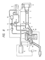
- Fig. 8 is a constructional view showing an automatic engine control system construction for controlling an air-fuel ratio of one embodiment in an apparatus for controlling an air-fuel ratio for use in an internal combustion engine according to the present invention; and
- Fig. 9 is a block diagram showing an automatic engine control system construction for controlling an air-fuel ratio of one embodiment in an electronic control unit and related apparatuses thereof shown in Fig. 8 according to the present invention.
- One embodiment of a method for controlling an air-fuel ratio for use in an internal combustion engine according to the present invention will be explained referring to drawings.
- The model calculation formulas described in the public known document are shown in the model calculation formulas (1) and (2) as mentioned above.
- In accordance with the division calculation both sides of the model calculation formulas (1) and (2) by the supply fuel amount (Gf)o = Qa/(A/F)o during the normal operation of the internal combustion engine, the numerical calculation formula (3) which being related to the fuel adhesion time βf(n) is indicated by a
control step 1 of a flow-chart shown in Fig. 1 is obtained. Further, the numerical calculation formula (4) being related to the transitional correction efficiency Kf which is indicated by acontrol step 4 of a flow-chart shown in Fig. 1 is obtained. - Going into details with respect to the obtain for the above mentioned numerical calculation formulas (3) and (4), the supply fuel amount Qa/(A/F) during the normal operation of the internal combustion engine is expressed as (Gf)o. In accordance with the division calculation both sides of the above mentioned model calculation formulas (1) and (2) by the supply fuel amount (Gf)o, the model calculation formula (1) is led by difference, Gf/(Gf)o is expressed as Kf (transitional correction coefficient) and the fuel adhesion time Mf/(Gf)o is expressed as βf, thereby the above mentioned numerical calculation formulas (3) and (4) are obtained, respectively.
- The fuel adhesion rate X to the inner wall surface portion of the intake air flow passage is determined mainly in accordance with the opening degree ϑth of the throttle valve and the engine temperature Tw. The fuel adhesion rate X has a characteristic as shown in Fig. 3.
- The evaporation time constant τ of the adhered fuel to the inner wall surface portion of the intake air flow passage is determined mainly in accordance with the opening degree ϑth of the throttle valve and the engine temperature Tw. The evaporation time constant τ has a characteristic as shown in Fig. 4.
- Namely, from the consideration on the qualitative face, the more the engine temperature Tw is low, the more both the value of the adhesion rate X and the value of the evaporation time constant τ become large. Also, the more the value of the opening degree ϑth of the throttle valve is large, the more both the value of the adhesion rate X and the value of the evaporation time constant τ become large.
- In replace of the above stated opening degree ϑth of the throttle valve, the fuel adhesion rate X and the evaporation time constant τ may be determined by using an intake air flow amount Qa, an intake pipe pressure, or a basic fuel injection pulse width Tp. Namely, a physical amount corresponding to a load to the internal combustion engine may be used therefor.
- The calculations shown in Fig. 1 are dealt repeatedly with at every predetermined calculation cycle ΔT. In a
control step 1 shown in Fig. 1, using the opening degree ϑth of the throttle valve and the engine temperature Tw, the fuel adhesion rate X and the evaporation time constant τ are determined in accordance with the characteristic shown in Fig. 3 and the characteristic shown in Fig. 4, respectively, and the fuel adhesion time βf is calculated therefrom. - In a
control step 2 shown in Fig. 1, it is judged whether or not there is during a fuel cut period. In case of YES, since the fuel supply is stopped, then in acontrol step 3 shown in Fig. 1 the transitional correction coefficient Kf is made at zero (Kf=0) and thecontrol step 3 is returned to thecontrol step 1. - The stop of the fuel supply is carried out such a case that an automobile vehicle operated under the deceleration operation, the vehicle speed of the automobile becomes vehicle abnormally high, or the engine speed N of the automobile vehicle becomes abnormally high etc..
- In case of during a non-fuel cut period or in case of NO in the
control step 2, since the fuel is supplied normally into the combustion chamber of the internal combustion engine, in acontrol step 4 shown in Fig. 1 the transitional correction coefficient Kf is calculated in accordance with the above stated calculation formula (4) and after thecontrol step 4 is returned to thecontrol step 1. - Fig. 2 is a flow-chart showing the calculation processing for calculating the fuel injection pulse width Ti. The fuel injection pulse width Ti is activated at every predetermined cycle.
- In a
control step 10 shown in Fig. 2, each of the intake air flow amount Qa, the opening degree ϑth of the throttle valve, the engine speed N, the engine temperature Tw is detected. In acontrol step 11 shown in Fig. 2, the engine temperature correction coefficient Kw is requested in accordance with using a map shown in thecontrol step 11. - In a
control step 12 shown in Fig. 2, the basic fuel injection pulse width Tp is calculated in accordance with the calculation formula Tp = Kf·Qa/N. In acontrol step 13 shown in Fig. 2, the calculation processing shown in Fig. 1 are carried out repeatedly, and the fuel injection pulse width Ti is determined by using the transitional correction coefficient Kf which is renewed or updated successively. In thecontrol step 13, Tb is an electric power source voltage correction coefficient. - Fig. 6 is an explanatory diagram showing a move of the value of the above stated transitional correction coefficient Kf. The transitional correction coefficient Kf changes in accordance with the opening degree ϑth of the throttle valve shown in Fig. 5.
- In case of during the normal operation period of the internal combustion engine, according to the calculation processing by using the above stated calculation formula (3), it converges to the following calculation formula (5).

- Therefore, the transitional correction coefficient Kf converges at a valve of 1.0 in accordance with the above stated calculation formula (4).
- In case of the rapid acceleration operation from the during the normal operation period, the fuel adhesion rate X to the inner surface portion of the intake air flow passage increases rapidly. Besides, in case of the rapid deceleration operation from the during the normal operation period, the fuel adhesion rate X to the inner surface portion of the intake air flow passage decreases rapidly.
- After that, since the fuel adhesion rate βf converges gradually in accordance with the above stated calculation formula (5), the value of the transitional correction coefficient Kf becomes larger than 1.0 during the acceleration operation of the internal combustion engine. Besides, the value of the transitional correction coefficient Kf becomes smaller than 1.0 during the deceleration operation of the internal combustion engine.
- Accordingly, the fluctuation of the air-fuel ratio during the transitional period of the internal combustion engine can be controlled or corrected well. Also, the fluctuation of the air-fuel ratio during the transitional period of the internal combustion engine can be compensated and then a predetermined air-fuel ratio can be maintained.
- One embodiment of an apparatus for controlling an air-fuel ratio for use in an internal combustion engine according to the present invention will be explained in detail as follows referring to Fig. 8 and Fig. 9.
- In Fig. 8, air from an
inlet portion 2 of anair cleaner 1 enters into acollector 6 via the hot wire typeair flow meter 3 for detecting an intake air flow amount Qa, aduct 4, and athrottle valve body 5 having a throttle valve for controlling the intake air flow amount Qa. In thecollector 6, the air is distributed into eachintake pipe 8 which communicates directly to the gasoline internal combustion engine 7 and inhaled into cylinders of the internal combustion engine 7. - Besides, fuel from a
fuel tank 9 is sucked and pressurized by afuel pump 10, and the fuel is supplied into a fuel supply system which comprises afuel damper 11, afuel filter 12, thefuel injector 13, and a fuelpressure control regulator 14. The fuel is controlled at a predetermined pressure value by the fuelpressure control regulator 14 and injected into therespective intake pipe 8 through thefuel injector 13 being disposed on theintake pipe 8. - Further, a signal for detecting the intake air flow amount Qa is outputted from the
air flow meter 3. This output signal from theair flow meter 3 is inputted into theelectronic control unit 15. Athrottle valve sensor 18 for detecting an opening degree ϑth of the throttle valve is installed to thethrottle valve body 5. Thethrottle valve sensor 18 works as a throttle valve opening degree detecting sensor and also as an idle switch. An output signal from thethrottle valve sensor 18 is inputted into theelectronic control unit 15. - A cooling water
temperature detecting sensor 20 for detecting cooling water temperature of the internal combustion engine 7 is installed to a main body of the internal combustion engine 7. An output signal from the cooling watertemperature detecting sensor 20 is inputted into theelectronic control unit 15. - In a
distributor 16, a crank angle detecting sensor is installed therein. The crank angle detecting sensor outputs a signal for detecting a fuel injection time, an ignition time, a standard signal, and the engine speed N. An output signal from the crank angle detecting sensor is inputted into theelectronic control unit 15. Anignition coil 17 is connected to thedistributor 16. - The
electronic control unit 15 comprises an execution apparatus including MPU, EP-RPM, RAM, A/D convertor and input circuits as shown in Fig. 9. In theelectronic control unit 15, a predetermined execution is carried out through the output signal from theair flow meter 3, the output signal from thedistributor 16 etc.. Thefuel injector 13 is operated by the various output signals obtained by the execution results in theelectronic control unit 15, then the necessary amount fuel is injected intorespective intake pipe 8.
Claims (10)
when a fuel adhesion rate to an inner wall surface portion of an intake air flow passage is expressed as X, an evaporation time constant of an adhered fuel to the inner wall surface portion of the intake air flow passage is expressed as τ, and a fuel adhesion time corresponding to a fuel adhesion amount to the inner wall surface portion of the intake air flow passage to a fuel supply amount during a normal operation of the internal combustion engine is expressed as βf, and a calculation cycle of the fuel adhesion time is expressed as ΔT,
a fuel supply amount during the transitional period of the internal combustion engine is controlled by a transitional correction coefficient Kf which is obtained in accordance with following formulas.
βf(n) = (1 -

the fuel adhesion rate X is determined in accordance with an opening degree of a throttle valve and the engine speed of the internal combustion engine.
the fuel adhesion rate X is requested by map indicating a characteristic of the opening degree of the throttle valve and a characteristic of the engine speed of the internal combustion engine.
the evaporation time constant τ is determined in accordance with an opening degree of a throttle valve and the engine speed of the internal combustion engine.
the evaporation time constant τ is requested by map indicating a characteristic of the opening degree of the throttle valve and a characteristic of the engine speed of the internal combustion engine.
when a fuel adhesion rate to an inner wall surface portion of an intake air flow passage is expressed as X, an evaporation time constant of an adhered fuel to the inner wall surface portion of the intake air flow passage is expressed as τ, a fuel adhesion time corresponding to a fuel adhesion amount to the inner wall surface portion of the intake air flow passage to a fuel supply amount during a normal operation of the internal combustion engine is expressed as βf, and a calculation cycle of the fuel adhesion time is expressed as ΔT,
said air-fuel ratio control apparatus further comprises a transitional correction coefficient calculation means for calculating a transitional correction coefficient Kf which is obtained in accordance with following formulas and a second fuel supply amount control means for controlling a fuel supply amount by using the transitional correction coefficient Kf.
βf(n) = (1 -

the fuel adhesion rate X is determined in accordance with an opening degree of a throttle valve and the engine speed of the internal combustion engine.
the fuel adhesion rate X is requested from a map indicating a characteristic of the opening degree of the throttle valve and a characteristic of the engine speed of the internal combustion engine.
the evaporation time constant τ is determined in accordance with an opening degree of a throttle valve and the engine speed of the internal combustion engine.
the evaporation time constant τ is requested from a map indicating a characteristic of the opening degree of the throttle valve and a characteristic of the engine speed of the internal combustion engine.
Applications Claiming Priority (2)
| Application Number | Priority Date | Filing Date | Title |
|---|---|---|---|
| JP232507/88 | 1988-09-19 | ||
| JP63232507A JPH07116963B2 (en) | 1988-09-19 | 1988-09-19 | Air-fuel ratio correction method and same correction device |
Publications (3)
| Publication Number | Publication Date |
|---|---|
| EP0360193A2 true EP0360193A2 (en) | 1990-03-28 |
| EP0360193A3 EP0360193A3 (en) | 1990-06-27 |
| EP0360193B1 EP0360193B1 (en) | 1992-12-02 |
Family
ID=16940413
Family Applications (1)
| Application Number | Title | Priority Date | Filing Date |
|---|---|---|---|
| EP89117223A Expired - Lifetime EP0360193B1 (en) | 1988-09-19 | 1989-09-18 | Method for controlling air-fuel ratio for use in internal combustion engine and apparatus for controlling the same |
Country Status (5)
| Country | Link |
|---|---|
| US (1) | US4995366A (en) |
| EP (1) | EP0360193B1 (en) |
| JP (1) | JPH07116963B2 (en) |
| KR (1) | KR900005046A (en) |
| DE (1) | DE68903715T2 (en) |
Cited By (2)
| Publication number | Priority date | Publication date | Assignee | Title |
|---|---|---|---|---|
| GB2290632A (en) * | 1994-06-16 | 1996-01-03 | Bosch Gmbh Robert | Control system for metering fuel in internal combustion engines |
| EP0752522A2 (en) * | 1995-07-06 | 1997-01-08 | Ford Motor Company Limited | An air/fuel controller for an engine |
Families Citing this family (11)
| Publication number | Priority date | Publication date | Assignee | Title |
|---|---|---|---|---|
| JPH0460132A (en) * | 1990-06-29 | 1992-02-26 | Mazda Motor Corp | Fuel control device of engine |
| JPH04311643A (en) * | 1991-04-10 | 1992-11-04 | Hitachi Ltd | Engine cylinder inflow air quantity computing method and fuel injection control method |
| US5307276A (en) * | 1991-04-25 | 1994-04-26 | Hitachi, Ltd. | Learning control method for fuel injection control system of engine |
| US5261370A (en) * | 1992-01-09 | 1993-11-16 | Honda Giken Kogyo Kabushiki Kaisha | Control system for internal combustion engines |
| JPH06264793A (en) * | 1993-03-12 | 1994-09-20 | Mazda Motor Corp | Fuel control device of engine |
| JPH07145771A (en) * | 1993-11-24 | 1995-06-06 | Honda Motor Co Ltd | Ignition timing control device for internal combustion engine |
| JPH0893529A (en) * | 1994-09-21 | 1996-04-09 | Honda Motor Co Ltd | Fuel injection controller for internal combustion engine |
| JPH08177556A (en) * | 1994-10-24 | 1996-07-09 | Nippondenso Co Ltd | Fuel supply quantity control device for internal combustion engine |
| JP3791032B2 (en) * | 1996-01-09 | 2006-06-28 | 日産自動車株式会社 | Fuel injection control device for internal combustion engine |
| KR100231278B1 (en) * | 1997-04-29 | 1999-12-01 | 류정열 | Air-fuel ratio control method of vehicle engine |
| JP2001329888A (en) * | 2000-05-18 | 2001-11-30 | Mitsubishi Electric Corp | Fuel injection control device for internal combustion engine |
Citations (4)
| Publication number | Priority date | Publication date | Assignee | Title |
|---|---|---|---|---|
| EP0026643A2 (en) * | 1979-09-27 | 1981-04-08 | Ford Motor Company Limited | Fuel metering system for an internal combustion engine |
| EP0184626A2 (en) * | 1984-11-26 | 1986-06-18 | Hitachi, Ltd. | Control method for a fuel injection engine |
| EP0258837A2 (en) * | 1986-09-01 | 1988-03-09 | Hitachi, Ltd. | Fuel control apparatus for internal combustion engines |
| US4852538A (en) * | 1985-10-29 | 1989-08-01 | Nissan Motor Co., Ltd. | Fuel injection control system for internal combustion engine |
Family Cites Families (5)
| Publication number | Priority date | Publication date | Assignee | Title |
|---|---|---|---|---|
| US4357923A (en) * | 1979-09-27 | 1982-11-09 | Ford Motor Company | Fuel metering system for an internal combustion engine |
| JPS588238A (en) * | 1981-07-06 | 1983-01-18 | Toyota Motor Corp | Fuel injection control method for fuel injection engine |
| US4667640A (en) * | 1984-02-01 | 1987-05-26 | Hitachi, Ltd. | Method for controlling fuel injection for engine |
| US4903668A (en) * | 1987-07-29 | 1990-02-27 | Toyota Jidosha Kabushiki Kaisha | Fuel injection system of an internal combustion engine |
| JPH01182552A (en) * | 1988-01-18 | 1989-07-20 | Hitachi Ltd | Device for controlling adaption of air-fuel ratio |
-
1988
- 1988-09-19 JP JP63232507A patent/JPH07116963B2/en not_active Expired - Fee Related
-
1989
- 1989-09-08 US US07/404,649 patent/US4995366A/en not_active Expired - Lifetime
- 1989-09-18 DE DE8989117223T patent/DE68903715T2/en not_active Expired - Fee Related
- 1989-09-18 EP EP89117223A patent/EP0360193B1/en not_active Expired - Lifetime
- 1989-09-19 KR KR1019890013439A patent/KR900005046A/en not_active Application Discontinuation
Patent Citations (4)
| Publication number | Priority date | Publication date | Assignee | Title |
|---|---|---|---|---|
| EP0026643A2 (en) * | 1979-09-27 | 1981-04-08 | Ford Motor Company Limited | Fuel metering system for an internal combustion engine |
| EP0184626A2 (en) * | 1984-11-26 | 1986-06-18 | Hitachi, Ltd. | Control method for a fuel injection engine |
| US4852538A (en) * | 1985-10-29 | 1989-08-01 | Nissan Motor Co., Ltd. | Fuel injection control system for internal combustion engine |
| EP0258837A2 (en) * | 1986-09-01 | 1988-03-09 | Hitachi, Ltd. | Fuel control apparatus for internal combustion engines |
Non-Patent Citations (1)
| Title |
|---|
| SAE-PAPER 81 04 94 * |
Cited By (5)
| Publication number | Priority date | Publication date | Assignee | Title |
|---|---|---|---|---|
| GB2290632A (en) * | 1994-06-16 | 1996-01-03 | Bosch Gmbh Robert | Control system for metering fuel in internal combustion engines |
| US5553593A (en) * | 1994-06-16 | 1996-09-10 | Robert Bosch Gmbh | Control system and method for metering the fuel in an internal combustion engine |
| GB2290632B (en) * | 1994-06-16 | 1998-08-12 | Bosch Gmbh Robert | Control method for metering fuel in internal combustion engines |
| EP0752522A2 (en) * | 1995-07-06 | 1997-01-08 | Ford Motor Company Limited | An air/fuel controller for an engine |
| EP0752522A3 (en) * | 1995-07-06 | 1999-03-03 | Ford Motor Company Limited | An air/fuel controller for an engine |
Also Published As
| Publication number | Publication date |
|---|---|
| DE68903715T2 (en) | 1993-05-13 |
| KR900005046A (en) | 1990-04-13 |
| DE68903715D1 (en) | 1993-01-14 |
| JPH0281935A (en) | 1990-03-22 |
| EP0360193B1 (en) | 1992-12-02 |
| EP0360193A3 (en) | 1990-06-27 |
| JPH07116963B2 (en) | 1995-12-18 |
| US4995366A (en) | 1991-02-26 |
Similar Documents
| Publication | Publication Date | Title |
|---|---|---|
| US4344399A (en) | Method and apparatus for controlling engine idling speed | |
| CA1193341A (en) | Electronic engine control system | |
| US4996965A (en) | Electronic engine control method and system for internal combustion engines | |
| US4811713A (en) | Vehicle engine controller | |
| EP0360193A2 (en) | Method for controlling air-fuel ratio for use in internal combustion engine and apparatus for controlling the same | |
| EP0352657B1 (en) | Method and apparatus for controlling throttle valve opening degree of internal combustion engines | |
| JPS6354126B2 (en) | ||
| US4938195A (en) | Atmospheric pressure detecting device for engine control | |
| EP0142856A2 (en) | Air-fuel ratio control apparatus for internal combustion engines | |
| US5615657A (en) | Method and apparatus for estimating intake air pressure and method and apparatus for controlling fuel supply for an internal combustion engine | |
| US4531490A (en) | Idling speed feedback control method having fail-safe function for abnormalities in functioning of crank angle position-detecting system of an internal combustion engine | |
| US4911133A (en) | Fuel injection control system of automotive engine | |
| US5148791A (en) | Method of electronic engine control for internal combustion engine having a plurality of cylinders | |
| US5134981A (en) | Fuel injection control method in an engine | |
| US5003956A (en) | Electronic fuel injection control system for a multi-fuel internal combustion engine and method therefore | |
| US4357828A (en) | Method of indicating a basic air-fuel ratio condition of an internal combustion engine | |
| US4299089A (en) | Secondary air control system in an internal combustion engine | |
| US4799380A (en) | Engine rotation speed detecting apparatus | |
| JPS6125961A (en) | Control of negative-pressure adjusting valve for exhaust gas recirculation control | |
| EP0535671A2 (en) | Fuel injection control device for internal combustion engine | |
| US4471743A (en) | Fuel injection control system | |
| US5537981A (en) | Airflow error correction method and apparatus | |
| EP0295651B1 (en) | Method and device for controlling the ignition timing of internal combustion engines | |
| US5427081A (en) | Internal combustion engine air intake regulating system | |
| JPS63124842A (en) | Electronic control fuel injection device |
Legal Events
| Date | Code | Title | Description |
|---|---|---|---|
| PUAI | Public reference made under article 153(3) epc to a published international application that has entered the european phase |
Free format text: ORIGINAL CODE: 0009012 |
|
| AK | Designated contracting states |
Kind code of ref document: A2 Designated state(s): DE FR GB |
|
| PUAL | Search report despatched |
Free format text: ORIGINAL CODE: 0009013 |
|
| AK | Designated contracting states |
Kind code of ref document: A3 Designated state(s): DE FR GB |
|
| 17P | Request for examination filed |
Effective date: 19900629 |
|
| 17Q | First examination report despatched |
Effective date: 19910212 |
|
| GRAA | (expected) grant |
Free format text: ORIGINAL CODE: 0009210 |
|
| AK | Designated contracting states |
Kind code of ref document: B1 Designated state(s): DE |
|
| REF | Corresponds to: |
Ref document number: 68903715 Country of ref document: DE Date of ref document: 19930114 |
|
| EN | Fr: translation not filed | ||
| PLBE | No opposition filed within time limit |
Free format text: ORIGINAL CODE: 0009261 |
|
| STAA | Information on the status of an ep patent application or granted ep patent |
Free format text: STATUS: NO OPPOSITION FILED WITHIN TIME LIMIT |
|
| 26N | No opposition filed | ||
| PGFP | Annual fee paid to national office [announced via postgrant information from national office to epo] |
Ref country code: DE Payment date: 20030908 Year of fee payment: 15 |
|
| PG25 | Lapsed in a contracting state [announced via postgrant information from national office to epo] |
Ref country code: DE Free format text: LAPSE BECAUSE OF NON-PAYMENT OF DUE FEES Effective date: 20050401 |