EP0359945A2 - Compressed-air expulsion system - Google Patents
Compressed-air expulsion system Download PDFInfo
- Publication number
- EP0359945A2 EP0359945A2 EP89113750A EP89113750A EP0359945A2 EP 0359945 A2 EP0359945 A2 EP 0359945A2 EP 89113750 A EP89113750 A EP 89113750A EP 89113750 A EP89113750 A EP 89113750A EP 0359945 A2 EP0359945 A2 EP 0359945A2
- Authority
- EP
- European Patent Office
- Prior art keywords
- compressed air
- wall
- noise
- housing
- ventilation device
- Prior art date
- Legal status (The legal status is an assumption and is not a legal conclusion. Google has not performed a legal analysis and makes no representation as to the accuracy of the status listed.)
- Granted
Links
Images

Classifications
-
- B—PERFORMING OPERATIONS; TRANSPORTING
- B60—VEHICLES IN GENERAL
- B60T—VEHICLE BRAKE CONTROL SYSTEMS OR PARTS THEREOF; BRAKE CONTROL SYSTEMS OR PARTS THEREOF, IN GENERAL; ARRANGEMENT OF BRAKING ELEMENTS ON VEHICLES IN GENERAL; PORTABLE DEVICES FOR PREVENTING UNWANTED MOVEMENT OF VEHICLES; VEHICLE MODIFICATIONS TO FACILITATE COOLING OF BRAKES
- B60T17/00—Component parts, details, or accessories of power brake systems not covered by groups B60T8/00, B60T13/00 or B60T15/00, or presenting other characteristic features
- B60T17/002—Air treatment devices
- B60T17/008—Silencer devices
-
- F—MECHANICAL ENGINEERING; LIGHTING; HEATING; WEAPONS; BLASTING
- F16—ENGINEERING ELEMENTS AND UNITS; GENERAL MEASURES FOR PRODUCING AND MAINTAINING EFFECTIVE FUNCTIONING OF MACHINES OR INSTALLATIONS; THERMAL INSULATION IN GENERAL
- F16L—PIPES; JOINTS OR FITTINGS FOR PIPES; SUPPORTS FOR PIPES, CABLES OR PROTECTIVE TUBING; MEANS FOR THERMAL INSULATION IN GENERAL
- F16L55/00—Devices or appurtenances for use in, or in connection with, pipes or pipe systems
- F16L55/02—Energy absorbers; Noise absorbers
- F16L55/027—Throttle passages
- F16L55/02745—Throttle passages by passing through a mass of particles or a porous member
-
- F—MECHANICAL ENGINEERING; LIGHTING; HEATING; WEAPONS; BLASTING
- F16—ENGINEERING ELEMENTS AND UNITS; GENERAL MEASURES FOR PRODUCING AND MAINTAINING EFFECTIVE FUNCTIONING OF MACHINES OR INSTALLATIONS; THERMAL INSULATION IN GENERAL
- F16L—PIPES; JOINTS OR FITTINGS FOR PIPES; SUPPORTS FOR PIPES, CABLES OR PROTECTIVE TUBING; MEANS FOR THERMAL INSULATION IN GENERAL
- F16L55/00—Devices or appurtenances for use in, or in connection with, pipes or pipe systems
- F16L55/02—Energy absorbers; Noise absorbers
- F16L55/033—Noise absorbers
- F16L55/0336—Noise absorbers by means of sound-absorbing materials
Definitions
- the invention relates to a compressed air ventilation device according to the preamble of patent claim 1.
- Such a compressed air venting device is known from EP 0 019 855.
- the invention is therefore based on the object of designing a compressed air venting device of the type mentioned at the outset in such a way that excessive build-up of pressure is prevented.
- the invention has the particular advantage that the arrangement of a pressure relief valve designed as a pressure relief valve between the ventilation space upstream of the noise-damping means and the expansion space downstream of the noise-damping means of the compressed air venting device, when a predetermined maximum dynamic pressure value in the ventilation space is exceeded, the dynamic pressure is reduced via the pressure relief valve.
- a significant impairment of the function of the devices upstream of the compressed air ventilation device or even destruction of these devices is avoided.
- An overpressure safety device acting in the manner of an overflow valve can also be provided in the housing wall of the compressed air venting device, so that the dynamic pressure is released directly to the atmosphere.
- a bypass channel can be provided between the ventilation space upstream of the noise damping means and the relaxation space downstream of the noise damping means, via which these two spaces are constantly connected to each other.
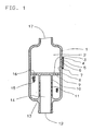
- FIG. 1 shows a muffler serving as a compressed air venting device, which has a housing (1) with an inlet opening (17) and an outlet opening (12) for compressed air.
- the muffler with its inlet opening is e.g. connected to the outlet of a pressure control valve which is arranged between a compressor and a compressed air reservoir.
- Noise-damping means are provided in the housing (1) of the noise damper, which subdivide the interior of the housing (1) into a ventilation space upstream of the noise-damping means and a relaxation space downstream of the noise-damping means.
- the noise-damping means consist of an annular wire mesh body (15) which surrounds a tube (10) running in the direction of the longitudinal axis of the housing (1).
- the wall of the tube (10) is provided with a plurality of passages (11) in the area surrounded by the wire mesh body (15).
- the tube is attached at one end to a plate (3) in a pressure-tight manner, which plate is attached to the inside wall of the housing in the ventilation space upstream of the noise-damping means and extends transversely to the longitudinal axis of the housing (1).
- the plate (3) has passages (9, 16) outside the area surrounded by the tube (10), via which the ventilation space serving as the inlet chamber (2) and connected upstream of the noise-damping means is continuously connected to the noise-damping means.
- the tube (10) opens with its end facing away from the plate (3), surrounding the outlet opening (12) on a base part (13) of the housing (1).
- the space delimited by the tube (10) is the relaxation space downstream of the noise-damping means and, in this exemplary embodiment, serves as an outlet chamber (14) for the compressed air.
- passage opening (8) which is closed by a plug inserted into it and serving as a closure member (6).
- the passage opening (8) and the closure member (6) are preferably designed to taper conically in the direction of the inlet chamber (2).
- the plate (6) can be designed as a type plate for the noise damper. It can be formed in one piece with the closure member (6).
- the plate (6) is held by two frame-like parts (4) and (7) which are molded onto the outer surface of the housing (1).
- the closure member (6) and the passage opening (8) have the function of a pressure relief valve, via which the ventilation space can be connected to the atmosphere.
- the compressed air When the excess compressed air is blown off from the pressure control valve upstream of the silencer, the compressed air enters the inlet chamber (2) of the silencer.
- the compressed air flows from the inlet chamber (2) through the passages (9, 16) provided in the plate (3) into the space containing the wire mesh body (15) and passes through the wire mesh and the passages provided in the tube (10) into the outlet chamber (14).
- the compressed air flows from the outlet chamber (14) through the outlet opening (12) to the atmosphere.
- the wire mesh body (14) becomes clogged, for example due to the deposition of coal or icy condensate, a back pressure builds up in the inlet chamber (2).
- the closure member (6) is affected by the dynamic pressure in the ventilation space (inlet chamber 2). pressed out of the passage opening (8) provided in the housing wall.
- the elastic plate (5) deforms to such an extent that it is also pressed out of its frame-like holding parts (4 and 7).
- the elastic plate (5) can be attached on one side to the wall of the housing.
- the noise damper shown in Figure 2 has essentially the same structure as the noise damper shown in Figure 1.
- the components that are the same as the components shown in FIG. 1 are provided with the same reference numbers.
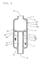
- Fig.2 shows a muffler, which has a housing (1) with an inlet opening (17) and an outlet opening (12) for compressed air.
- Noise-damping means are provided in the housing (1) of the noise damper, which subdivide the interior of the housing (1) into a ventilation space upstream of the noise-damping means and a relaxation space downstream of the noise-damping means.
- the noise-damping means consist of an annular wire mesh body (15) which surrounds a tube (10) running in the direction of the longitudinal axis of the housing (1).
- the wall of the tube (10) is that of the wire mesh body (15) surrounding area with a plurality of passages (11).
- One end of the tube (10) is fastened in a pressure-tight manner to a plate (3), which is attached to the inside wall of the housing in the ventilation space upstream of the noise-damping means and extends transversely to the longitudinal axis of the housing (1).
- the plate (3) divides the ventilation space upstream of the noise-damping means into an inlet chamber (2) connected to the inlet opening (17) and an expansion chamber (19).
- the inlet chamber (2) is continuously connected to the expansion chamber (19) via passages (9, 16) provided in the plate (3).
- the tube (10) opens with its end facing away from the plate (3) surrounding the outlet opening (12) provided in the base part (13) of the housing (1), on the base part (13).
- the space delimited by the inner wall of the tube (10) is the relaxation space downstream of the noise-damping means and, in this exemplary embodiment, serves as an outlet chamber (14) for the compressed air.
- passage opening (8) which is closed by a plug inserted into it and serving as a closure member (6).
- the passage opening (8) and the closure member (6) are preferably designed to taper conically in the direction of the inlet chamber (2).
- the plate (5) is held by two frame-like parts (4 and 7) which are molded onto the outer surface of the housing (1).
- an opening (20) designed as a bypass channel is arranged near the plate (3).
- the opening (20) preferably has a throttle point.
- the expansion chamber (19) is continuously connected to the outlet chamber (14) via the opening (20).
- the compressed air flowing into the inlet chamber (2) passes through the passages (9, 16) provided in the plate (3) into the expansion chamber (19).
- the compressed air expands as much as possible and on the one hand passes directly through the wire mesh body (15) and the passages (11) provided in the tube (10) into the outlet chamber (14) and on the other hand through the bypass channel (20) the expansion joint (19) into the outlet chamber (14).
- the compressed air is discharged from the outlet chamber (14) through the outlet opening (12) to the atmosphere.
- the silencer remains functional, since the dynamic pressure that slowly builds up in the expansion chamber (19) is released to the atmosphere via the bypass channel (20) and the outlet chamber (14).
- the closure member (6) pressed out of the back pressure from the passage opening (8) in the wall of the housing (1) and deforms the elastic plate (5) in the direction away from the outer surface of the housing (1). During this process, the plate (6) is pressed out of its frame-like holding parts (4, 7).
- the overpressure protection device (8, 5, 6, 4, 7) provided in the wall of the housing (1) also works when the plate (3) is designed as a perforated plate and the openings of the perforated plate clog, so that in the Inlet chamber (2) creates a back pressure that is too high.
- the noise damper shown in Figure 3 has essentially the same structure as the noise damper shown in Figure 2. Instead of a bypass channel, an opening (24) is provided in the wall of the tube (10), which is closed by an elastic tab (25.
- the opening (24) and the tab (25) form a pressure relief valve Wall of the housing (1) provided overpressure protection device is designed according to the embodiment of Figure 3 as a predetermined breaking point.
- the predetermined breaking point consists of a preferably circular wall part (23) which is preferably thinner than the rest of the wall of the housing (1).
- the thinner wall part (23) is held by a bead (21), the one end (21) of the bead with the wall of the housing (1) and the other end (22) of the Bead, which is thinner than the wall (1) and thus forms the actual predetermined breaking point, is connected to the thinner wall part (23).
- the wall part (23) held by the bead can also have the same thickness as the housing wall (1). In such a case, however, the transition area between the bead (21) and the wall part (23) must be made thinner than the wall of the housing (1) in order to obtain a precisely defined fracture profile.
- a simple non-return valve which consists of an opening and a non-return valve, can of course also be used as the excess pressure safety device or as the excess pressure valve.
- a check valve can be arranged in the wall of the housing (1) or in the wall of the tube (10).
- a stopper (6) a ball closing the passage opening (8) can be provided.
- the pressure relief valve on or in a component which separates the ventilation space upstream of the noise-damping means from the relaxation space downstream of the noise-damping means.
- the pressure relief valve can be provided in the plate (3) instead of in the wall of the housing (1).
- the pressure relief valve must be arranged in the area of the plate (3) which is delimited by the free interior of the tube (10).
- each space such as the expansion chamber, the inlet chamber, is the To look at the inlet port. That is, each room, which is upstream of the noise-damping means, has the function of a ventilation room, regardless of whether it is located in a housing, as shown in the exemplary embodiments of the invention, or in a part of a device, in or on which noise damping means are arranged.
- the bypass channel can be designed as a channel penetrating the noise-damping means.
- Such a channel can contain a pressure relief valve (wall closing the channel passage cross section with predetermined breaking point or check valve).
- the pressure relief device referred to above as the pressure relief valve, need not of course include the typical features of a valve, such as the valve seat and valve body. As already described, it can be designed as a predetermined breaking point in a wall (also in the wall of a pipe) or as a bursting tab.
- the rupture flap is a flap which closes the opening in a wall and is a component of this wall and, in the event of overpressure in a space adjacent to this wall, is pushed more or less out of the opening. After the overpressure has dropped, the tab returns to its original position.
- the pressure relief valve can be arranged in each partial area of a wall delimiting the ventilation space (the partial area delimiting the inlet chamber or the expansion chamber of the wall of the housing 1 or a wall part of a device or also a wall part delimiting the connecting piece).
Abstract
Description
Die Erfindung betrifft eine Druckluft-Entlüftungseinrichtung gemäß dem Oberbegriff des Patentanspruchs 1.The invention relates to a compressed air ventilation device according to the preamble of
Eine derartige Druckluft-Entlüftungseinrichtung ist aus der EP 0 019 855 bekannt.Such a compressed air venting device is known from EP 0 019 855.
Bei einer Druckluft-Entlüftungseinrichtung ist es nicht auszuschließen, daß nach längerer Betriebszeit die Druckluft-Durchlässigkeit der geräuschdämpfenden Mittel im Gehäuseinnenraum der Druckluft-Entlüftungseinrichtung nachläßt, z.B. durch gefrierendes Kondensat oder durch Ablagerung von Ölkohle.
Dies kann zur Folge haben, daß sich im Gehäuseinnenraum ein unerwünschter Staudruck bildet.In the case of a compressed air ventilation device, it cannot be ruled out that after a long period of operation the compressed air permeability of the noise-damping agents in the interior of the compressed air ventilation device decreases, for example due to freezing condensate or due to the deposition of oil carbon.
This can have the consequence that an undesirable dynamic pressure forms in the interior of the housing.
Der Erfindung liegt deshalb die Aufgabe zugrunde, eine Druckluft-Entlüftungseinrichtung der eingangs erwähnten Art so auszubilden, daß eine übermäßige Staudruckbildung verhindert wird.The invention is therefore based on the object of designing a compressed air venting device of the type mentioned at the outset in such a way that excessive build-up of pressure is prevented.
Diese Aufgabe wird durch die in den Patentansprüchen 1 und 2 angegebenen Erfindungen gelöst.
Weiterbildungen und vorteilhafte Ausgestaltungen der in den Patentansprüchen 1 und 2 angegebenen Lösungsmöglichkeiten sind in den Unteransprüchen aufgezeigt.This object is achieved by the inventions specified in
Further developments and advantageous refinements of the possible solutions specified in
Die Erfindung bietet insbesondere den Vorteil, daß durch die Anordnung einer als Überdruckventil ausgebildeten Überdrucksicherung zwischen dem den geräuschdämpfenden Mitteln vorgeschalteten Entlüftungsraum und dem den geräuschdampfenden Mitteln nachgeschalteten Entspannungsraum der Druckluft-Entlüftungseinrichtung bei Überschreiten eines vorbestimmbaren maximalen Staudruckwertes im Entlüftungsraum der Staudruck über das Überdruckventil abgebaut wird. Eine nennenswerte Beeinträchtigung der Funktion der der Druckluft-Entlüftungseinrichtung vorgeschalteten Geräte oder gar eine Zerstörung dieser Geräte wird vermieden. Eine nach Art eines Überströmventils wirkende Überdrucksicherungseinrichtung kann auch in der Gehäusewand der Druckluft-Entlüftungseinrichtung vorgesehen werden, so daß der Staudruck direkt zur Atmosphäre hin abgebaut wird.The invention has the particular advantage that the arrangement of a pressure relief valve designed as a pressure relief valve between the ventilation space upstream of the noise-damping means and the expansion space downstream of the noise-damping means of the compressed air venting device, when a predetermined maximum dynamic pressure value in the ventilation space is exceeded, the dynamic pressure is reduced via the pressure relief valve. A significant impairment of the function of the devices upstream of the compressed air ventilation device or even destruction of these devices is avoided. An overpressure safety device acting in the manner of an overflow valve can also be provided in the housing wall of the compressed air venting device, so that the dynamic pressure is released directly to the atmosphere.
Wie im Patentanspruch 2 angegeben, kann zwischen dem den geräuschdämpfenden Mitteln vorgeschalteten Entlüftungsraum und dem den geräuschdampfenden Mitteln nachgeschalteten Entspannungsraum ein Bypaß-Kanal vorgesehen werden, über welchen diese beiden Räume ständig miteinander verbunden sind.As indicated in
Wird zwischen den beiden besagten Räumen ein Bypaß-Kanal oder eine z.B. als ein in Richtung auf den den geräuschdampfenden Mittel nachgeschalteten Entspannungsraum zu in die Offenstellung bringbares Überdruckventil vorgesehen, so bleibt die Druckluft-Entlüftungseinrichtung auch dann noch funktionsfähig, wenn die geräuschdämpfenden Mittel teilweise zugesetzt sind.If a bypass channel or a e.g. As a pressure relief valve which can be brought into the open position in the direction of the relaxation space downstream of the noise-damping means, the compressed air ventilation device remains functional even when the noise-damping means are partially clogged.
Anhand der Zeichnung werden nachfolgend drei Ausführungsbeispiele der Erfindung näher erläutert.Three exemplary embodiments of the invention are explained in more detail below with the aid of the drawing.
Es zeigen:
- Fig.1 eine als Geräuschdampfer ausgebildete Druckluft-Entlüftungseinrichtung mit einer Einlaß kammer und einer Auslaßkammer, wobei in dem Bereich der Gehäusewand des Geräuschdampfers, welche die Einlaßkammer begrenzt, ein Überdruckventil vorgesehen ist;
- Fig.2 einen Geräuschdampfer mit einer Einlaßkammer, einer Expansionskammer und einer Auslaßkammer, wobei ein die Expansionskammer und die Auslaßkammer verbindender Bypaß und ein in der die Einlaßkammer begrenzenden Wand des Gehäuses vorgesehenes Überdruckventil vorgesehen ist und
- Fig.3 einen Geräuschdämpfer mit einer als Sollbruchstelle ausgebildeten Überdrucksicherung in der die Einlaßkammer begrenzenden Wand und einem in der die Expansionskammer von der Auslaßkammer trennenden Wand des Geräuschdampfers vorgesehenen Überdruckventil.
- 1 shows a compressed air venting device designed as a muffler with an inlet chamber and an outlet chamber, a pressure relief valve being provided in the region of the housing wall of the muffler, which delimits the inlet chamber;
- 2 shows a muffler with an inlet chamber, an expansion chamber and an outlet chamber, a bypass connecting the expansion chamber and the outlet chamber and a pressure relief valve being provided in the wall of the housing delimiting the inlet chamber and
- 3 shows a noise damper with a pressure relief device designed as a predetermined breaking point in the wall delimiting the inlet chamber and a pressure relief valve provided in the wall of the noise damper separating the expansion chamber from the outlet chamber.
In Fig.1 ist ein als Druckluft-Entlüftungseinrichtung dienender Geräuschdampfer dargestellt, der ein Gehäuse (1) mit einer Einlaßöffnung (17) und einer Auslaßöffnung (12) für Druckluft aufweist. Der Geräuschdampfer ist mit seiner Einlaßöffnung z.B. mit dem Auslaß eines Druckregelventils verbunden, welches zwischen einem Kompressor und einem Druckluftvorratsbehälter angeordnet ist.1 shows a muffler serving as a compressed air venting device, which has a housing (1) with an inlet opening (17) and an outlet opening (12) for compressed air. The muffler with its inlet opening is e.g. connected to the outlet of a pressure control valve which is arranged between a compressor and a compressed air reservoir.
Im Gehäuse (1) des Geräuschdämpfers sind geräuschdampfende Mittel vorgesehen, welche den Innenraum des Gehäuses (1) in einen den geräuschdampfenden Mitteln vorgeschalteten zu entlüftenden Entlüftungsraum und einen den geräuschdämpfenden Mitteln nachgeschalteten Entspannungsraum unterteilen.Noise-damping means are provided in the housing (1) of the noise damper, which subdivide the interior of the housing (1) into a ventilation space upstream of the noise-damping means and a relaxation space downstream of the noise-damping means.
Die geräuschdampfenden Mittel bestehen in diesem Ausführungsbeispiel aus einem ringförmig ausgebildeten Drahtgewebekörper (15), der ein in Richtung der Längsachse des Gehäuses (1) verlaufendes Rohr (10) umgibt. Die Wand des Rohres (10) ist in dem vom Drahtgewebekörper (15) umgebenen Bereich mit einer Vielzahl von Durchlässen (11) versehen.
Das Rohr ist mit seinem einen Ende an einer Platte (3) druckdicht befestigt, die in dem den geräuschdämpfenden Mitteln vorgeschalteten Entlüftungsraum quer zur Längsachse des Gehäuses (1) verlaufend an der Gehäuseinnenwand befestigt ist.In this exemplary embodiment, the noise-damping means consist of an annular wire mesh body (15) which surrounds a tube (10) running in the direction of the longitudinal axis of the housing (1). The wall of the tube (10) is provided with a plurality of passages (11) in the area surrounded by the wire mesh body (15).
The tube is attached at one end to a plate (3) in a pressure-tight manner, which plate is attached to the inside wall of the housing in the ventilation space upstream of the noise-damping means and extends transversely to the longitudinal axis of the housing (1).
Die Platte (3) weist außerhalb des vonm Rohr (10) umgebenen Bereiches Durchlässe (9, 16) auf, über welche der als Einlaßkammer (2) dienende, den geräuschdämpfenden Mitteln vorgeschaltet Entlüftungsraum ständig mit den geräuschdämpfenden Mitteln verbunden ist.The plate (3) has passages (9, 16) outside the area surrounded by the tube (10), via which the ventilation space serving as the inlet chamber (2) and connected upstream of the noise-damping means is continuously connected to the noise-damping means.
Das Rohr (10) mündet mit seinem der Platte (3) abgewandten Ende, die Auslaßöffnung (12) umgebend an einem Bodenteil (13) des Gehäuses (1). Der vom Rohr (10) begrenzte Raum ist der den geräuschdampfenden Mitteln nachgeschaltete Entspannungsraum und dient in diesem Ausführungsbeispiel als Auslaßkammer (14) für die Druckluft.The tube (10) opens with its end facing away from the plate (3), surrounding the outlet opening (12) on a base part (13) of the housing (1). The space delimited by the tube (10) is the relaxation space downstream of the noise-damping means and, in this exemplary embodiment, serves as an outlet chamber (14) for the compressed air.
In dem die Einlaßkammer (2) begrenzenden Bereich der Wand des Gehäuses (1) ist eine Durchlaßöffnung (8) angeordnet, die von einem in diese eingesetzten, als Verschlußglied (6) dienenden Stopfen verschlossen wird. Die Durchlaßöffnung (8) und das Verschlußglied (6) sind vorzugsweise in Richtung auf die Einlaßkammer (2) zu sich konisch verjüngend ausgebildet.In the area of the wall of the housing (1) delimiting the inlet chamber (2) there is a passage opening (8) which is closed by a plug inserted into it and serving as a closure member (6). The passage opening (8) and the closure member (6) are preferably designed to taper conically in the direction of the inlet chamber (2).
Eine auf der äußeren Mantelfläche des Gehäuses (1) aufliegende und die Durchlaßöffnung (8) überdeckende Platte (5), die vorzugsweise aus einem elastischen Werkstoff besteht, hält das Verschlußglied (6) in der Durchlaßöffnung (8).
Die Platte (6) kann als Typenschild für den Geräuschdämpfer ausgebildet sein. Sie kann einstückig mit dem Verschlußglied (6) ausgebildet sein.
Die Platte (6) wird von zwei rahmenartigen Teilen (4) und (7), die an die Mantelfläche des Gehäuses (1) angeformt sind, gehalten. Das Verschlußglied (6) und die Durchlaßöffnung (8) haben die Funktion eines Überdruckventils, über welches der Entlüftungsraum mit der Atmosphäre verbindbar ist.A plate (5) lying on the outer surface of the housing (1) and covering the passage opening (8), which preferably consists of an elastic material, holds the closure member (6) in the passage opening (8).
The plate (6) can be designed as a type plate for the noise damper. It can be formed in one piece with the closure member (6).
The plate (6) is held by two frame-like parts (4) and (7) which are molded onto the outer surface of the housing (1). The closure member (6) and the passage opening (8) have the function of a pressure relief valve, via which the ventilation space can be connected to the atmosphere.
Die Funktion des im vorstehenden beschriebenen Geräuschdämpfers wird nachfolgend näher erläutert.The function of the noise damper described above is explained in more detail below.
Beim Abblasen der überschüssigen Druckluft aus dem den Geräuschdampfer vorgeschalteten Druckregelventil gelangt die Druckluft in die Einlaßkammer (2) des Geräuschdampfers. Von der Einlaßkammer (2) strömt die Druckluft durch die in der Platte (3) vorgesehenen Durchlässe (9, 16) in den den Drahtgewebekörper (15) enthaltenden Raum und gelangt durch das Drahtgewebe sowie die im Rohr (10) vorgesehenen Durchlässe in die Auslaßkammer (14). Von der Auslaßkammer (14) strömt die Druckluft durch die Auslaßöffnung (12) zur Atmosphäre hin.When the excess compressed air is blown off from the pressure control valve upstream of the silencer, the compressed air enters the inlet chamber (2) of the silencer. The compressed air flows from the inlet chamber (2) through the passages (9, 16) provided in the plate (3) into the space containing the wire mesh body (15) and passes through the wire mesh and the passages provided in the tube (10) into the outlet chamber (14). The compressed air flows from the outlet chamber (14) through the outlet opening (12) to the atmosphere.
Setzt sich der Drahtgewebekörper (14), z.B. durch Ablagerung von Ölkohle oder durch vereistes Kondensat, zu, so baut sich in der Einlaßkammer (2) ein Staudruck auf.
Sobald der Staudruck eine vorbestimmte maximal zulässige Höhe überschritten hat, wird das Verschlußglied (6) vom Staudruck im Entlüftungsraum (Einlaßkammer 2) aus der in der Gehäusewand vorgesehenen Durchlaßöffnung (8) herausgedrückt.
Bei diesem Vorgang verformt sich die elastische Platte (5) so weit, daß sie ebenfalls aus ihren rahmenartigen Halteteilen (4 und 7) herausgedrückt wird.If the wire mesh body (14) becomes clogged, for example due to the deposition of coal or icy condensate, a back pressure builds up in the inlet chamber (2).
As soon as the dynamic pressure has exceeded a predetermined maximum permissible level, the closure member (6) is affected by the dynamic pressure in the ventilation space (inlet chamber 2). pressed out of the passage opening (8) provided in the housing wall.
During this process, the elastic plate (5) deforms to such an extent that it is also pressed out of its frame-like holding parts (4 and 7).
Durch die jetzt freigegebene Durchlaßöffnung (8) in der Wand des Gehäuses (1) baut sich der Staudruck in der Einlaßkammer (2) zur Atmosphäre hin ab.
Um ein Verlustiggehen der elastischen Platte (5) bei diesem Vorgang zu verhindern, kann die elastische Platte (5) einseitig an der Wand des Gehäuses befestigt sein.Through the now released passage opening (8) in the wall of the housing (1), the dynamic pressure in the inlet chamber (2) is reduced to the atmosphere.
In order to prevent loss of the elastic plate (5) during this process, the elastic plate (5) can be attached on one side to the wall of the housing.
Der in Fig.2 dargestellte Geräuschdämpfer weist im wesentlichen den gleichen Aufbau auf wie der in Fig.1 gezeigte Geräuschdämpfer.
Der besseren Übersicht halber sind die den in Fig.1 gezeigten Bauteilen gleichen Bauteile mit gleichen Bezugsziffern versehen.The noise damper shown in Figure 2 has essentially the same structure as the noise damper shown in Figure 1.
For the sake of a better overview, the components that are the same as the components shown in FIG. 1 are provided with the same reference numbers.
Fig.2 zeigt einen Geräuschdampfer, der ein Gehäuse (1) mit einer Einlaßöffnung (17) und einer Auslaßöffnung (12) für Druckluft aufweist.
Im Gehäuse (1) des Geräuschdämpfers sind geräuschdampfende Mittel vorgesehen, welche den Innenraum des Gehäuses (1) in einen den geräuschdämpfenden Mitteln vorgeschalteten Entlüftungsraum und einen den geräuschdampfenden Mitteln nachgeschalteten Entspannungsraum unterteilen.Fig.2 shows a muffler, which has a housing (1) with an inlet opening (17) and an outlet opening (12) for compressed air.
Noise-damping means are provided in the housing (1) of the noise damper, which subdivide the interior of the housing (1) into a ventilation space upstream of the noise-damping means and a relaxation space downstream of the noise-damping means.
Die geräuschdampfenden Mittel bestehen in diesem Ausführungsbeispiel aus einem ringförmig ausgebildeten Drahtgewebekörper (15), der ein in Richtung der Längsachse des Gehäuses (1) verlaufendes Rohr (10) umgibt. Die Wand des Rohres (10) ist in dem vom Drahtgewebe körper (15) umgebenen Bereich mit einer Vielzahl von Durchlässen (11) versehen.In this exemplary embodiment, the noise-damping means consist of an annular wire mesh body (15) which surrounds a tube (10) running in the direction of the longitudinal axis of the housing (1). The wall of the tube (10) is that of the wire mesh body (15) surrounding area with a plurality of passages (11).
Das Rohr (10) ist mit seinem einen Ende an einer Platte (3) druckdicht befestigt, die in dem den geräuschdampfenden Mitteln vorgeschalteten Entlüftungsraum quer zur Längsachse des Gehäuses (1) verlaufend an der Gehäuseinnenwand befestigt ist.
Die Platte (3) unterteilt den den geräuschdämpfenden Mitteln vorgeschalteten Entlüftungsraum in eine mit der Einlaßöffnung (17) verbundene Einlaßkammer (2) und eine Expansionskammer (19). Die Einlaßkammer (2) ist über in der Platte (3) vorgesehene Durchlässe (9, 16) ständig mit der Expansionskammer (19) verbunden.One end of the tube (10) is fastened in a pressure-tight manner to a plate (3), which is attached to the inside wall of the housing in the ventilation space upstream of the noise-damping means and extends transversely to the longitudinal axis of the housing (1).
The plate (3) divides the ventilation space upstream of the noise-damping means into an inlet chamber (2) connected to the inlet opening (17) and an expansion chamber (19). The inlet chamber (2) is continuously connected to the expansion chamber (19) via passages (9, 16) provided in the plate (3).
Die Expansionskammer (19) wird von der der Platte (3) zugewandten Stirnfläche (18) des Drahtgewebekörpers (15), einer Ringfläche der Platte (3), der Innenwand des Gehäuses (1) und dem nicht vom Drahtgewebekörper (15) umgebenen Bereich des Rohres (10) begrenzt.The expansion chamber (19) of the plate (3) facing the end face (18) of the wire mesh body (15), an annular surface of the plate (3), the inner wall of the housing (1) and the area not surrounded by the wire mesh body (15) Pipe (10) limited.
Das Rohr (10) mündet mit seinem der Platte (3) abgewandten Ende die im Bodenteil (13) des Gehäuses (1) vorgesehene Auslaßöffnung (12) umgebend, am Bodenteil (13).
Der von der Innenwand des Rohres (10) begrenzte Raum ist der den geräuschdämpfenden Mitteln nachgeschaltete Entspanungsraum und dient in diesem Ausführungsbeispiel als Auslaßkammer (14) für die Druckluft.The tube (10) opens with its end facing away from the plate (3) surrounding the outlet opening (12) provided in the base part (13) of the housing (1), on the base part (13).
The space delimited by the inner wall of the tube (10) is the relaxation space downstream of the noise-damping means and, in this exemplary embodiment, serves as an outlet chamber (14) for the compressed air.
In dem die Einlaßkammer (2) begrenzenden Bereich der Wand des Gehäuses (1) ist eine Durchlaßöffnung (8) angeordnet, die von einem in diese eingesetzten, als Verschlußglied (6) dienenden Stopfen verschlossen wird. Die Durchlaßöffnung (8) und das Verschlußglied (6) sind vorzugsweise in Richtung auf die Einlaßkammer (2) zu sich konisch verjüngend ausgebildet.In the area of the wall of the housing (1) delimiting the inlet chamber (2) there is a passage opening (8) which is closed by a plug inserted into it and serving as a closure member (6). The passage opening (8) and the closure member (6) are preferably designed to taper conically in the direction of the inlet chamber (2).
Eine auf der äußeren Mantelfläche des Gehäuses (1) aufliegende und die Durchlaßöffnung (8) überdeckende Platte (5) aus einem elastischen Werkstoff hält das Verschlußglied (6) in der Durchlaßöffnung (8). Die Platte (5) wird von zwei rahmenartigen Teilen (4 und 7), die an die Mantelfläche des Gehäuses (1) angeformt sind, gehalten.A plate (5) made of an elastic material and resting on the outer surface of the housing (1) and covering the passage opening (8) holds the closure member (6) in the passage opening (8). The plate (5) is held by two frame-like parts (4 and 7) which are molded onto the outer surface of the housing (1).
In dem Bereich des Rohres (10), welches nicht von dem Drahtgewebekörper (15) umgeben ist, ist nahe der Platte (3) eine als Bypaß-Kanal ausgebildete Öffnung (20) angeordnet. Die Öffnung (20) weist vorzugsweise eine Drosselstelle auf. Über die Öffnung (20) ist die Expansionskammer (19) ständig mit der Auslaßkammer (14) verbunden.In the area of the tube (10) which is not surrounded by the wire mesh body (15), an opening (20) designed as a bypass channel is arranged near the plate (3). The opening (20) preferably has a throttle point. The expansion chamber (19) is continuously connected to the outlet chamber (14) via the opening (20).
Die Funktion des Geräuschdämpfers nach Fig.2 wird nachfolgend näher erläutert.The function of the noise damper according to Figure 2 is explained in more detail below.
Die in die Einlaßkammer (2) einströmende Druckluft gelangt durch die in der Platte (3) vorgesehenen Durchlässe (9, 16) in die Expansionskammer (19). In der Expansionskammer (19) entspannt sich die Druckluft weitestgehend und gelangt einerseits durch den Drahtgewebekörper (15) und die im Rohr (10) vorgesehenen Durchlässe (11) in die Auslaßkammer (14) und andererseits durch den Bypaß-Kanal (20) direkt von der Expansionskanmer (19) in die Auslaßkammer (14). Aus der Auslaßkammer (14) wird die Druckluft durch die Auslaßöffnung (12) zur Atmosphäre hin abgeführt.The compressed air flowing into the inlet chamber (2) passes through the passages (9, 16) provided in the plate (3) into the expansion chamber (19). In the expansion chamber (19) the compressed air expands as much as possible and on the one hand passes directly through the wire mesh body (15) and the passages (11) provided in the tube (10) into the outlet chamber (14) and on the other hand through the bypass channel (20) the expansion joint (19) into the outlet chamber (14). The compressed air is discharged from the outlet chamber (14) through the outlet opening (12) to the atmosphere.
Setzt sich der Drahtgewebekörper durch gefrierendes Kondensat teilweise zu, so bleibt der Geräuschdämpfer weiterhin funktionsfähig, da sich der in der Expansionskammer (19) langsam aufbauende Staudruck über den Bypaß-Kanal (20) und die Auslaßkammer (14) zur Atmosphäre hin abbaut.If the wire mesh body is partially blocked by freezing condensate, the silencer remains functional, since the dynamic pressure that slowly builds up in the expansion chamber (19) is released to the atmosphere via the bypass channel (20) and the outlet chamber (14).
Setzt sich, bedingt durch widrige Umstände auch der Bypaß-Kanal (20) zu, so daß der Staudruck in der Expansionskammer (19) und auch in der Einlaßkammer (2) eine maximal zulässige Höhe überschreitet, so wird das Ver-schlußglied (6) vom Staudruck aus der Durchlaßöffnung (8) in der Wand des Gehäuses (1) herausgedrückt und verformt dabei die elastische Platte (5) in Richtung von der äußeren Mantelfläche des Gehäuses (1) weg. Bei diesem Vorgang wird auch die Platte (6) aus ihren rahmenartigen Halteteilen (4, 7) herausgedrückt.If, due to adverse circumstances, the bypass channel (20) also clogs, so that the dynamic pressure in the expansion chamber (19) and also in the inlet chamber (2) exceeds a maximum permissible height, the closure member (6) pressed out of the back pressure from the passage opening (8) in the wall of the housing (1) and deforms the elastic plate (5) in the direction away from the outer surface of the housing (1). During this process, the plate (6) is pressed out of its frame-like holding parts (4, 7).
In gleicher Weise arbeitet die in der Wand des Gehäuses (1) vorgesehene Überdrucksicherungseinrichtung (8, 5, 6, 4, 7) auch, wenn die Platte (3) als Lochblech ausgebildet ist und sich die Öffnungen des Lochbleches zusetzen, so daß in der Einlaßkammer (2) ein zu hoher Staudruck entsteht.In the same way, the overpressure protection device (8, 5, 6, 4, 7) provided in the wall of the housing (1) also works when the plate (3) is designed as a perforated plate and the openings of the perforated plate clog, so that in the Inlet chamber (2) creates a back pressure that is too high.
Der in Fig.3 gezeigte Geräuschdämpfer weist im wesentlichen den gleichen Aufbau auf wie der in Fig.2 dargestellte Geräuschdampfers.
Anstelle eines Bypaß-Kanals ist in der Wand des Rohres (10) jedoch eine Öffnung (24) vorgesehen, die von einer elastischen Lasche (25 verschlossen wird. Die Öffnung (24) und die Lasche (25) bilden ein Überdruckventil. Die in der Wand des Gehäuses (1) vorgesehene Überdrucksicherungseinrichtung ist gemäß dem Ausführungsbeispiel nach Fig.3 als Sollbruchstelle ausgebildet.The noise damper shown in Figure 3 has essentially the same structure as the noise damper shown in Figure 2.
Instead of a bypass channel, an opening (24) is provided in the wall of the tube (10), which is closed by an elastic tab (25. The opening (24) and the tab (25) form a pressure relief valve Wall of the housing (1) provided overpressure protection device is designed according to the embodiment of Figure 3 as a predetermined breaking point.
Die Sollbruchstelle besteht aus einem vorzugsweise kreisrunden Wandungsteil (23), welches vorzugsweise dünner ausgebildet ist als die übrige Wand des Gehäuses (1).
Das dünnere Wandungsteil (23) wird von einer Wulst (21) gehalten, wobei das eine Ende (21) der Wulst mit der Wand des Gehäuses (1) und das andere Ende (22) der Wulst, welches dünner ausgebildet ist als die Wand (1) und so die eigentliche Sollbruchstelle bildet, mit dem dünneren Wandungsteil (23) verbunden ist.The predetermined breaking point consists of a preferably circular wall part (23) which is preferably thinner than the rest of the wall of the housing (1).
The thinner wall part (23) is held by a bead (21), the one end (21) of the bead with the wall of the housing (1) and the other end (22) of the Bead, which is thinner than the wall (1) and thus forms the actual predetermined breaking point, is connected to the thinner wall part (23).
Das von der Wulst gehaltene Wandungsteil (23) kann auch die gleiche Stärke aufweisen wie die Gehäusewand (1). Jedoch muß in einem solchen Fall der Übergangsbereich zwischen Wulst (21) und Wandungsteil (23) dünner ausgebildet sein als die Wand des Gehäuses (1), um einen genau definierten Bruchverlauf zu erhalten.The wall part (23) held by the bead can also have the same thickness as the housing wall (1). In such a case, however, the transition area between the bead (21) and the wall part (23) must be made thinner than the wall of the housing (1) in order to obtain a precisely defined fracture profile.
Als Überdrucksicherungseinrichtung bzw, als Überdruckventil kann selbstverständlich auch ein einfaches Rückschlagventil Verwendung finden welches aus einer Öffnung und einer Rückschlagklappe besteht.
Ein solches Rückschlagventil kann in der Wand des Gehäuses (1) oder auch in der Wand des Rohres (10) angeordnet sein. Anstelle eines Stopfens (6) kann eine die Durchlaßöffnung (8) verschließende Kugel vorgesehen werden.A simple non-return valve, which consists of an opening and a non-return valve, can of course also be used as the excess pressure safety device or as the excess pressure valve.
Such a check valve can be arranged in the wall of the housing (1) or in the wall of the tube (10). Instead of a stopper (6), a ball closing the passage opening (8) can be provided.
Es ist selbstverständlich auch möglich, das Überdruckventil an oder in einem Bauteil anzuordnen, welches den den geräuschdämpfenden Mitteln vorgeschalteten Entlüftungsraum von dem den geräuschdämpfenden Mitteln nachgeschalteten Entspannungsraum trennt.It is of course also possible to arrange the pressure relief valve on or in a component which separates the ventilation space upstream of the noise-damping means from the relaxation space downstream of the noise-damping means.
In Anlehnung an die Ausführungsbeispiele gemäß den Figuren 1 bis 3 kann das Überdruckventil anstatt in der Wand des Gehäuses (1) in der Platte (3) vorgesehen werden. Die Überdruckventil ist in einem solchen Fall in dem Bereich der Platte (3) anzuordnen, der von dem freien Innenraum des Rohres (10) begrenzt wird.Based on the exemplary embodiments according to FIGS. 1 to 3, the pressure relief valve can be provided in the plate (3) instead of in the wall of the housing (1). In such a case, the pressure relief valve must be arranged in the area of the plate (3) which is delimited by the free interior of the tube (10).
Als zu entlüftender Entlüftungsraum ist jeder Raum, wie z.B. die Expansionskammer, die Einlaßkammer, der Einlaßstutzen anzusehen. D.h. jeder Raum, der den geräuschdämpfenden Mitteln vorgeschaltet ist, hat die Funktion eines Entlüftungsraumes, und zwar unabhängig davon, ob er in einem Gehäuse, wie in den Ausführungsbeispielen der Erfindung dargestellt, oder in einem Teil eines Gerätes gelegen ist, in oder an welchen die geräuschdämpfenden Mittel angeordnet sind.As a ventilation space to be vented, each space, such as the expansion chamber, the inlet chamber, is the To look at the inlet port. That is, each room, which is upstream of the noise-damping means, has the function of a ventilation room, regardless of whether it is located in a housing, as shown in the exemplary embodiments of the invention, or in a part of a device, in or on which noise damping means are arranged.
Ist ein den geräuschdämpfenden Mitteln nachgeschalteter Entspannungsraum vorgesehen, so kann dieser auch direkt von der diesem Entspannungsraum zugewandten Seite der geräuschdämpfenden Mittel begrenzt werden. Eine Wand, wie in den Ausführungsbeispielen dargestellt, die Wand des Rohres (10), ist nicht erforderlich.
Der Bypaß-Kanal kann als ein die geräuschdämpfenden Mittel durchdringender Kanal ausgebildet sein. Ein solcher Kanal kann ein Überdruckventil enthalten (den Kanaldurchlaßquerschnitt verschließende Wand mit Sollbruchstelle oder Rückschlagklappe).
Die Überdruckbegrenzungseinrichtung, vorstehend als Überdruckventil bezeichnet, braucht natürlich nicht die typischen Merkmale eines Ventils zu enthalten, wie Ventilsitz und Ventilkörper. Sie kann, wie bereits beschrieben, als Sollbruchstelle in einer Wand (auch in der Wand eines Rohres) oder als Berstlasche ausgebildet sein. Die Berstlasche ist eine die Öffnung in einer Wand verschließende Lasche, die Bestandteil dieser Wand ist, und bei Überdruck in einem an diese Wand angrenzenden Raum mehr oder weniger weit aus der Öffnung herausgedrückt wird. Nach Abfall des Überdruckes kehrt die Lasche in ihre Ausgangsstellung zurück.
Das Überdruckventil kann in jedem Teilbereich einer den Entlüftungsraum begrenzenden Wand angeordnet sein (der die Einlaßkammer oder die Expansionskammer begrenzende Teilbereich der Wand des Gehäuses 1 oder eines Wandungsteils eines Gerätes oder auch ein den Anschlußstutzen begrenzendes Wandungsteil).If a relaxation room is provided downstream of the noise-damping means, this can also be limited directly by the side of the noise-damping means facing this relaxation space. A wall, as shown in the exemplary embodiments, the wall of the tube (10) is not required.
The bypass channel can be designed as a channel penetrating the noise-damping means. Such a channel can contain a pressure relief valve (wall closing the channel passage cross section with predetermined breaking point or check valve).
The pressure relief device, referred to above as the pressure relief valve, need not of course include the typical features of a valve, such as the valve seat and valve body. As already described, it can be designed as a predetermined breaking point in a wall (also in the wall of a pipe) or as a bursting tab. The rupture flap is a flap which closes the opening in a wall and is a component of this wall and, in the event of overpressure in a space adjacent to this wall, is pushed more or less out of the opening. After the overpressure has dropped, the tab returns to its original position.
The pressure relief valve can be arranged in each partial area of a wall delimiting the ventilation space (the partial area delimiting the inlet chamber or the expansion chamber of the wall of the
Claims (22)
dadurch gekennzeichnet, daß ein Überdruckventil (8, 6 bzw. 22, 23) vorgesehen ist, über welches der Entlüftungsraum (2, 19) mit der Atmosphäre und/oder mit einem den geräuschdämpfenden Mitteln (15) gegebenenfalls nachgeschalteten Entspannungsraum (14) verbindbar ist.
characterized in that a pressure relief valve (8, 6 or 22, 23) is provided, by means of which the ventilation space (2, 19) can be connected to the atmosphere and / or to a relaxation space (14) which may be connected downstream of the noise-reducing means (15) .
dadurch gekennzeichnet, daß der Entlüftungsraum (2, 19) ständig über einen Bypaß-Kanal (20) mit einem den geräuschdämpfenden Mitteln (15) nachgeschalteten Entspannungsraum (14) verbunden ist.
characterized in that the ventilation space (2, 19) is continuously connected via a bypass duct (20) to a relaxation space (14) connected downstream of the noise-damping means (15).
Applications Claiming Priority (2)
| Application Number | Priority Date | Filing Date | Title |
|---|---|---|---|
| DE3832029A DE3832029C2 (en) | 1988-09-21 | 1988-09-21 | Compressed air ventilation device |
| DE3832029 | 1988-09-21 |
Related Child Applications (2)
| Application Number | Title | Priority Date | Filing Date |
|---|---|---|---|
| EP19930109340 Division EP0565136A3 (en) | 1988-09-21 | 1989-07-26 | Compressed air and venting system |
| EP93109340.5 Division-Into | 1989-07-26 |
Publications (3)
| Publication Number | Publication Date |
|---|---|
| EP0359945A2 true EP0359945A2 (en) | 1990-03-28 |
| EP0359945A3 EP0359945A3 (en) | 1992-02-12 |
| EP0359945B1 EP0359945B1 (en) | 1994-08-31 |
Family
ID=6363389
Family Applications (2)
| Application Number | Title | Priority Date | Filing Date |
|---|---|---|---|
| EP89113750A Expired - Lifetime EP0359945B1 (en) | 1988-09-21 | 1989-07-26 | Compressed-air expulsion system |
| EP19930109340 Ceased EP0565136A3 (en) | 1988-09-21 | 1989-07-26 | Compressed air and venting system |
Family Applications After (1)
| Application Number | Title | Priority Date | Filing Date |
|---|---|---|---|
| EP19930109340 Ceased EP0565136A3 (en) | 1988-09-21 | 1989-07-26 | Compressed air and venting system |
Country Status (2)
| Country | Link |
|---|---|
| EP (2) | EP0359945B1 (en) |
| DE (2) | DE3832029C2 (en) |
Cited By (2)
| Publication number | Priority date | Publication date | Assignee | Title |
|---|---|---|---|---|
| DE102017122215A1 (en) * | 2017-09-26 | 2019-03-28 | Knorr-Bremse Systeme für Nutzfahrzeuge GmbH | Silencer for compressed air systems and a method for its production |
| CN110864180A (en) * | 2019-11-07 | 2020-03-06 | 哈尔滨工程大学 | High-efficient compact sea water pipeline silencer |
Families Citing this family (8)
| Publication number | Priority date | Publication date | Assignee | Title |
|---|---|---|---|---|
| DE4205458A1 (en) * | 1992-02-22 | 1993-08-26 | Bosch Gmbh Robert | MUFFLERS FOR BLOWERS |
| DE4412517C2 (en) * | 1994-04-12 | 1997-01-16 | Bbm Technik Ges Fuer Die Verwe | Blow-out silencer |
| FR2834312B1 (en) * | 2001-12-27 | 2006-11-24 | Acoustique Ind Sarl Soc D | SILENT DIFFUSER FOR GAS RELAXATION |
| DE102008029489A1 (en) | 2008-06-20 | 2009-12-24 | Wabco Gmbh | Silencer for compressed air systems of vehicles |
| DE102016100140A1 (en) | 2016-01-05 | 2017-07-06 | Knorr-Bremse Systeme für Nutzfahrzeuge GmbH | Silencer for a compressed air system of a vehicle, in particular a commercial vehicle |
| DE102016100139A1 (en) | 2016-01-05 | 2017-07-06 | Knorr-Bremse Systeme für Nutzfahrzeuge GmbH | Silencer for a compressed air system of a vehicle, in particular commercial vehicle |
| CN112212116A (en) * | 2020-10-16 | 2021-01-12 | 张贵杰 | Utilize gasbag structure to realize soft tuber pipe butt joint installation device of amortization |
| CN112503287B (en) * | 2020-11-27 | 2023-06-27 | 江苏盐阜电站阀门辅机制造有限公司 | Muffler for temperature and pressure reducing valve |
Citations (4)
| Publication number | Priority date | Publication date | Assignee | Title |
|---|---|---|---|---|
| DE1801447A1 (en) * | 1967-10-10 | 1969-06-04 | Everett Wilhelm S | Pulsation damper for flow means |
| FR2451530A1 (en) * | 1979-03-15 | 1980-10-10 | Wabco Fahrzeugbremsen Gmbh | MUFFLERS FOR VALVES OR PRESSURE REGULATORS OF COMPRESSED AIR BRAKES |
| EP0019855A1 (en) * | 1979-06-02 | 1980-12-10 | WABCO Westinghouse Fahrzeugbremsen GmbH | Silencer for valve arrangements in pneumatic installations |
| DE3343587A1 (en) * | 1983-12-02 | 1984-07-12 | Daimler-Benz Ag, 7000 Stuttgart | Silencer for flowing gases |
Family Cites Families (3)
| Publication number | Priority date | Publication date | Assignee | Title |
|---|---|---|---|---|
| US2766840A (en) * | 1951-04-21 | 1956-10-16 | Webster Electric Co Inc | Vibration absorber |
| FR2232976A5 (en) * | 1973-06-08 | 1975-01-03 | Bertin & Cie | Exhaust gas pipe sound damping - by incasing apertured pipe to define tortous gas path through coaxial cylinder walls |
| US3920095A (en) * | 1974-02-01 | 1975-11-18 | Brunswick Corp | Free flow sound attenuating device and method of using |
-
1988
- 1988-09-21 DE DE3832029A patent/DE3832029C2/en not_active Expired - Lifetime
-
1989
- 1989-07-26 EP EP89113750A patent/EP0359945B1/en not_active Expired - Lifetime
- 1989-07-26 EP EP19930109340 patent/EP0565136A3/en not_active Ceased
- 1989-07-26 DE DE58908264T patent/DE58908264D1/en not_active Expired - Fee Related
Patent Citations (4)
| Publication number | Priority date | Publication date | Assignee | Title |
|---|---|---|---|---|
| DE1801447A1 (en) * | 1967-10-10 | 1969-06-04 | Everett Wilhelm S | Pulsation damper for flow means |
| FR2451530A1 (en) * | 1979-03-15 | 1980-10-10 | Wabco Fahrzeugbremsen Gmbh | MUFFLERS FOR VALVES OR PRESSURE REGULATORS OF COMPRESSED AIR BRAKES |
| EP0019855A1 (en) * | 1979-06-02 | 1980-12-10 | WABCO Westinghouse Fahrzeugbremsen GmbH | Silencer for valve arrangements in pneumatic installations |
| DE3343587A1 (en) * | 1983-12-02 | 1984-07-12 | Daimler-Benz Ag, 7000 Stuttgart | Silencer for flowing gases |
Cited By (3)
| Publication number | Priority date | Publication date | Assignee | Title |
|---|---|---|---|---|
| DE102017122215A1 (en) * | 2017-09-26 | 2019-03-28 | Knorr-Bremse Systeme für Nutzfahrzeuge GmbH | Silencer for compressed air systems and a method for its production |
| US11505171B2 (en) | 2017-09-26 | 2022-11-22 | Knorr-Bremse Systeme Fuer Nutzfahrzeuge Gmbh | Noise damper for compressed air systems and a method for the production of same |
| CN110864180A (en) * | 2019-11-07 | 2020-03-06 | 哈尔滨工程大学 | High-efficient compact sea water pipeline silencer |
Also Published As
| Publication number | Publication date |
|---|---|
| EP0359945B1 (en) | 1994-08-31 |
| EP0565136A2 (en) | 1993-10-13 |
| EP0359945A3 (en) | 1992-02-12 |
| DE3832029A1 (en) | 1990-03-22 |
| EP0565136A3 (en) | 1993-10-20 |
| DE3832029C2 (en) | 1997-12-11 |
| DE58908264D1 (en) | 1994-10-06 |
Similar Documents
| Publication | Publication Date | Title |
|---|---|---|
| EP1165333B2 (en) | Pneumatic system for a motor vehicle | |
| DE4409252C2 (en) | Air suspension system | |
| DE102007011256B4 (en) | Compressed air supply device with improved regeneration capability | |
| EP0884203B1 (en) | Height control device for vehicles with air springs | |
| EP1046521A2 (en) | Height control device for vehicles with air springs | |
| EP0359945B1 (en) | Compressed-air expulsion system | |
| DE3514989A1 (en) | Compressed air supply device for compressed air systems for vehicles | |
| EP0155346A2 (en) | Vehicle tyre pressure-regulating device | |
| EP0596220B1 (en) | Compressed air and venting system | |
| DE102008053994A1 (en) | Pressure limiting device for pressurized air supply system in commercial vehicle, has discharge valve opened and/or closed by passing discharge borehole through piston element, and switching chamber connected with outlet connection | |
| EP0019855A1 (en) | Silencer for valve arrangements in pneumatic installations | |
| EP1134467A1 (en) | Valve installation in a refrigeration system | |
| DE2910209A1 (en) | NOISE SHOCK ABSORBER FOR VALVE DEVICES IN COMPRESSED AIR BRAKE SYSTEMS | |
| EP1040947A2 (en) | Vehicle air conditioner | |
| EP0537483B1 (en) | Air dryer for air pressure installation chargeable by compressor, especially air pressure brake systems for vehicles | |
| EP0659621B1 (en) | Pressure limiting device | |
| EP0289712B1 (en) | Pressure regulating valve | |
| EP0097223B1 (en) | Device for damping air blasted from valve installations | |
| WO2008141889A1 (en) | Airbag arrangement | |
| EP0093842A1 (en) | Silencer for valve installations in compressed-air breaking systems | |
| EP0845601B1 (en) | Starting valve | |
| EP0359948A2 (en) | Noise absorber | |
| EP0114192A1 (en) | Trailer control valve | |
| DE102016115360A1 (en) | Overflow valve for at least partially closing and opening a fluid conduit system | |
| EP0846605B1 (en) | Pneumatic brake installation |
Legal Events
| Date | Code | Title | Description |
|---|---|---|---|
| PUAI | Public reference made under article 153(3) epc to a published international application that has entered the european phase |
Free format text: ORIGINAL CODE: 0009012 |
|
| AK | Designated contracting states |
Kind code of ref document: A2 Designated state(s): DE FR GB IT NL SE |
|
| PUAL | Search report despatched |
Free format text: ORIGINAL CODE: 0009013 |
|
| AK | Designated contracting states |
Kind code of ref document: A3 Designated state(s): DE FR GB IT NL SE |
|
| 17P | Request for examination filed |
Effective date: 19920117 |
|
| 17Q | First examination report despatched |
Effective date: 19921117 |
|
| RAP1 | Party data changed (applicant data changed or rights of an application transferred) |
Owner name: WABCO VERMOEGENSVERWALTUNGS-GMBH |
|
| GRAA | (expected) grant |
Free format text: ORIGINAL CODE: 0009210 |
|
| AK | Designated contracting states |
Kind code of ref document: B1 Designated state(s): DE FR GB IT NL SE |
|
| XX | Miscellaneous (additional remarks) |
Free format text: TEILANMELDUNG 93109340.5 EINGEREICHT AM 26/07/89. |
|
| ITF | It: translation for a ep patent filed |
Owner name: JACOBACCI CASETTA & PERANI S.P.A. |
|
| REF | Corresponds to: |
Ref document number: 58908264 Country of ref document: DE Date of ref document: 19941006 |
|
| ET | Fr: translation filed | ||
| GBT | Gb: translation of ep patent filed (gb section 77(6)(a)/1977) |
Effective date: 19941214 |
|
| EAL | Se: european patent in force in sweden |
Ref document number: 89113750.7 |
|
| PLBE | No opposition filed within time limit |
Free format text: ORIGINAL CODE: 0009261 |
|
| STAA | Information on the status of an ep patent application or granted ep patent |
Free format text: STATUS: NO OPPOSITION FILED WITHIN TIME LIMIT |
|
| RAP2 | Party data changed (patent owner data changed or rights of a patent transferred) |
Owner name: WABCO GMBH |
|
| 26N | No opposition filed | ||
| NLT2 | Nl: modifications (of names), taken from the european patent patent bulletin |
Owner name: WABCO GMBH |
|
| PGFP | Annual fee paid to national office [announced via postgrant information from national office to epo] |
Ref country code: GB Payment date: 19980717 Year of fee payment: 10 |
|
| PGFP | Annual fee paid to national office [announced via postgrant information from national office to epo] |
Ref country code: NL Payment date: 19980731 Year of fee payment: 10 Ref country code: FR Payment date: 19980731 Year of fee payment: 10 |
|
| PG25 | Lapsed in a contracting state [announced via postgrant information from national office to epo] |
Ref country code: GB Free format text: LAPSE BECAUSE OF NON-PAYMENT OF DUE FEES Effective date: 19990726 |
|
| PG25 | Lapsed in a contracting state [announced via postgrant information from national office to epo] |
Ref country code: FR Free format text: THE PATENT HAS BEEN ANNULLED BY A DECISION OF A NATIONAL AUTHORITY Effective date: 19990731 |
|
| PG25 | Lapsed in a contracting state [announced via postgrant information from national office to epo] |
Ref country code: NL Free format text: LAPSE BECAUSE OF NON-PAYMENT OF DUE FEES Effective date: 20000201 |
|
| GBPC | Gb: european patent ceased through non-payment of renewal fee |
Effective date: 19990726 |
|
| NLV4 | Nl: lapsed or anulled due to non-payment of the annual fee |
Effective date: 20000201 |
|
| REG | Reference to a national code |
Ref country code: FR Ref legal event code: ST |
|
| PGFP | Annual fee paid to national office [announced via postgrant information from national office to epo] |
Ref country code: DE Payment date: 20060731 Year of fee payment: 18 Ref country code: IT Payment date: 20060731 Year of fee payment: 18 |
|
| EUG | Se: european patent has lapsed | ||
| PG25 | Lapsed in a contracting state [announced via postgrant information from national office to epo] |
Ref country code: DE Free format text: LAPSE BECAUSE OF NON-PAYMENT OF DUE FEES Effective date: 20080201 Ref country code: SE Free format text: LAPSE BECAUSE OF NON-PAYMENT OF DUE FEES Effective date: 20070727 |
|
| PGFP | Annual fee paid to national office [announced via postgrant information from national office to epo] |
Ref country code: SE Payment date: 20060706 Year of fee payment: 18 |
|
| PG25 | Lapsed in a contracting state [announced via postgrant information from national office to epo] |
Ref country code: IT Free format text: LAPSE BECAUSE OF NON-PAYMENT OF DUE FEES Effective date: 20070726 |