EP0359724A2 - Cold cathodes for fluorescent lamps - Google Patents
Cold cathodes for fluorescent lamps Download PDFInfo
- Publication number
- EP0359724A2 EP0359724A2 EP89830389A EP89830389A EP0359724A2 EP 0359724 A2 EP0359724 A2 EP 0359724A2 EP 89830389 A EP89830389 A EP 89830389A EP 89830389 A EP89830389 A EP 89830389A EP 0359724 A2 EP0359724 A2 EP 0359724A2
- Authority
- EP
- European Patent Office
- Prior art keywords
- depressions
- tape
- cold cathode
- pair
- individual
- Prior art date
- Legal status (The legal status is an assumption and is not a legal conclusion. Google has not performed a legal analysis and makes no representation as to the accuracy of the status listed.)
- Granted
Links
Images
Classifications
-
- H—ELECTRICITY
- H01—ELECTRIC ELEMENTS
- H01J—ELECTRIC DISCHARGE TUBES OR DISCHARGE LAMPS
- H01J61/00—Gas-discharge or vapour-discharge lamps
- H01J61/02—Details
- H01J61/24—Means for obtaining or maintaining the desired pressure within the vessel
- H01J61/28—Means for producing, introducing, or replenishing gas or vapour during operation of the lamp
-
- H—ELECTRICITY
- H01—ELECTRIC ELEMENTS
- H01J—ELECTRIC DISCHARGE TUBES OR DISCHARGE LAMPS
- H01J7/00—Details not provided for in the preceding groups and common to two or more basic types of discharge tubes or lamps
- H01J7/14—Means for obtaining or maintaining the desired pressure within the vessel
- H01J7/18—Means for absorbing or adsorbing gas, e.g. by gettering
- H01J7/186—Getter supports
-
- H—ELECTRICITY
- H01—ELECTRIC ELEMENTS
- H01J—ELECTRIC DISCHARGE TUBES OR DISCHARGE LAMPS
- H01J61/00—Gas-discharge or vapour-discharge lamps
- H01J61/02—Details
- H01J61/24—Means for obtaining or maintaining the desired pressure within the vessel
-
- H—ELECTRICITY
- H01—ELECTRIC ELEMENTS
- H01J—ELECTRIC DISCHARGE TUBES OR DISCHARGE LAMPS
- H01J7/00—Details not provided for in the preceding groups and common to two or more basic types of discharge tubes or lamps
- H01J7/14—Means for obtaining or maintaining the desired pressure within the vessel
Definitions
- Mercury dispensing getter devices are well known in the art. See for example Japanese Utility Model Application Publication N o 50-10679 and USA Patents N o 3,722,976; 3,657,589 and 3,733,194 among others.
- a prior art cold cathode electrode 100 comprising two strips 102, 102′ of nickel plated iron.
- Outer facing surface of strip 102 has pressure bonded thereon a layer 106 of powdered 84% Zr - 16% Al non-evaporable getter alloy.
- the outer surface (not shown) of strip 102′ has a similar layer.
- Inner facing surface 108 of strip 102′ has a layer 110 of powdered Ti3Hg mercury releasing intermetallic compound.
- Strips 102, 102′ can be cut from continuous lengths of strip commercially available under the code name St 101-505/CTL/NI/6.3-3 from SAES GETTERS S.P.A. Milan, Italy.
- Strips 102, 102′ are welded to supports 112, 112′ at points 114, 114′.
- the welding points 114, 114′ must take place in the border of the strip as shown in the border 116 of strip 102. This is to avoid any possible release of mercury or destruction of the gettering properties of the Zr-Al alloy in the assembly process of the cold cathode prior to insertion in the fluorescent tube.
- the dimensions of the strips 102, 102′ are approximately 0.65 cm width by 0.6 cm length, the accurate positioning of two such strips together with the support electrodes is extremely difficult. There is a severe risk of overheating, during welding, of both the mercury releasing alloy and the non-evaporable getter alloy. Furthermore attempts to miniaturize even further the cold cathode lead to a reduction of the quantities of Ti3Hg present and hence a reduction of the quantity of mercury released within the fluorescent lamp. Also a reduction of the quantity of non-evaporable getter material present does not ensure sufficient removal of the dangerous residual gases released during the life of the fluorescent lamp.
- Metallic tape 200 can be of any metal suitable for supporting a mercury vapour releasing material and a non-evaporable getter metal.
- tape 200 is of nickel plated iron.
- Tape 200 has a continuous series of depressions 202, 202′, 204, 204′, 206, 206′. Depressions 202, 202′ form within said tape a pair of individual depressions. Successive depressions 204, 204′ provide another pair of individual depressions. Again successive individual depressions 206, 206′ form a further pair of depressions, and so on. Each pair of depressions is separated by a distance greater than the distance separating the individual depressions.
- the depressions are of approximately oval shape as shown in Fig. 2 such that their length is greater than their width. The oval shape shown in the drawings can also be described as the shape of a race track or a cartouche.
- FIG. 3 there is shown a cross-section 300 along lines 3-3′ of Fig. 2 of depression 204.
- Cross section 300 shows a metallic tape containing depression 204.
- Mercury vapour releasing material 302 preferably comprises a powdered mixture of intermetallic compound Ti3Hg with a powdered non-evaporable getter metal preferably comprising an alloy of 84% Zr - 16% Al.
- Cold cathode 400 is formed from a small length of tape 402 formed for instance by cutting a small length of tape 200 as shown in Fig. 2 along the lines indicated by alpha and beta in Fig. 2. Small strip of tape 402 is then folded along line gamma as indicated in both Fig. 4 and Fig. 2. Line gamma lies in the plane of the tape 402 midway between the two depressions within the tape 402 and perpendicular to the tape length. The tape 402 is bent through an angle of approximately 180°. As shown in Fig. 4 the bending has taken place so that the depressions face outwardly. This allows the cathode to occupy the smallest possible space.
- the cathode 400 may be welded to a wire support 404 as shown in both Figs. 4 and 5.
- the wire support 404 is shown as being internal to the cathode 400 but it will be realized that small length of tape 402 may be more closely folded and wire support 404 may be external to the cold cathode 400.
- a miniature fluorescent lamp 600 comprising a cylindrical glass envelope 602 and end seals 604, 604′.
- Miniature fluorescent lamp 600 incorporates two cold cathodes 400, 400′ being held within the miniature fluorescent lamp by means of seals 604, 604′ respectively.
- a continuous length of nickel plated iron strip having a width of 2.5 mm is taken and a continuous series of depressions are formed therein such that the depressions form successive pair of individual depressions.
- Each depression has a width of approximately 1.5 mm and a length of 3.5 mm.
- the separation between the individual depression of each pair is 2.5 mm whereas the separation between successive pairs of depressions is 5 mm.
- Each depression is filled with approximately 5 mg of a 50% by weight mixture of an intermetallic compound Ti3Hg and 50% by weight of 84% Zr - 16% Al non-evaporable getter material.
- a cold cathode is produced by cutting a small length of the tape and folding it as described above and it is welded to a wire support. Two such electrodes are used to produce a miniature fluorescent lamp as shown in Fig. 6. The cathode can be heated during a manufacturing process to release mercury and subsequently act as a cold cathode and getter device.
Abstract
Description
- Mercury dispensing getter devices are well known in the art. See for example Japanese Utility Model Application Publication No 50-10679 and USA Patents No 3,722,976; 3,657,589 and 3,733,194 among others.
- However such publications give no teachings regarding the miniaturization of cold cathode fluorescent lamps which are required, for instance, in the back-lighting of liquid crystal displays for automobile instrument panels, pocket television sets, and the like, or simply for lighting purposes.
- One particular attempt to produce a miniaturized cold cathode fluorescent lamp has been to use two small pieces of a strip coated with both Ti₃Hg and an alloy of 84% Zr - 16% Al spot welded to wire support leads. However these cathodes are still relatively large and they also have the defect that insufficient mercury is released to ensure the desirable lifetime of the fluorescent lamp.
- It is therefore an object of the present invention to provide an improved metallic tape supporting a mercury vapour releasing material admixed with a non-evaporable getter metal in a continuous series of depressions within said tape the depressions forming successive pairs of individual depressions each pair of depressions being separated by a distance greater than the distance separating the individual depressions, useful in the manufacture of a cold cathode for a miniaturized fluorescent lamp.
- It is another object of the present invention to provide an improved cold cathode for use in the manufacture of a miniaturized fluorescent lamp.
- It is yet a further object of the present invention to provide an improved miniaturized fluorescent lamp.
- These and other objects and advantages of the present invention will become apparent with reference to the following description and drawings wherein:
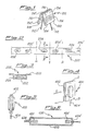
- Fig. 1 shows a perspective view of a prior art cold cathode for use in a fluorescent lamp;
- Fig. 2 shows a plan view of a mercury releasing metal getter tape of the present invention;
- Fig. 3 is an enlarged cross-sectional view along line 3-3′ of Fig. 2;
- Fig. 4 is a perspective view of a cold cathode produced using a portion of the tape shown in Fig. 2;
- Fig. 5 is a view of the cold cathode of Fig. 4 taken along arrow A of Fig. 4; and
- Fig. 6 is a cross sectional representation of a miniaturized fluorescent lamp utilizing a cold cathode of the present invention.
- Referring now to the drawings and in particular to Fig. 1 there is shown a prior art cold cathode electrode 100 comprising two
strips strip 102 has pressure bonded thereon alayer 106 of powdered 84% Zr - 16% Al non-evaporable getter alloy. The outer surface (not shown) ofstrip 102′ has a similar layer. Inner facingsurface 108 ofstrip 102′ has alayer 110 of powdered Ti₃Hg mercury releasing intermetallic compound.Strips -
Strips points welding points border 116 ofstrip 102. This is to avoid any possible release of mercury or destruction of the gettering properties of the Zr-Al alloy in the assembly process of the cold cathode prior to insertion in the fluorescent tube. - As the dimensions of the
strips - Referring now to Fig. 2 there is shown a
metallic tape 200 of the present invention.Metallic tape 200 can be of any metal suitable for supporting a mercury vapour releasing material and a non-evaporable getter metal. Preferablytape 200 is of nickel plated iron.Tape 200 has a continuous series ofdepressions Depressions Successive depressions individual depressions - Referring now to Fig. 3 there is shown a
cross-section 300 along lines 3-3′ of Fig. 2 ofdepression 204. -
Cross section 300 shows a metallictape containing depression 204. Intodepression 204 there is compressed a mercuryvapour releasing material 302. Mercuryvapour releasing material 302 preferably comprises a powdered mixture of intermetallic compound Ti₃Hg with a powdered non-evaporable getter metal preferably comprising an alloy of 84% Zr - 16% Al. - Referring now to Fig. 4 there is shown a
cold cathode 400 of the present invention.Cold cathode 400 is formed from a small length oftape 402 formed for instance by cutting a small length oftape 200 as shown in Fig. 2 along the lines indicated by alpha and beta in Fig. 2. Small strip oftape 402 is then folded along line gamma as indicated in both Fig. 4 and Fig. 2. Line gamma lies in the plane of thetape 402 midway between the two depressions within thetape 402 and perpendicular to the tape length. Thetape 402 is bent through an angle of approximately 180°. As shown in Fig. 4 the bending has taken place so that the depressions face outwardly. This allows the cathode to occupy the smallest possible space. Thecathode 400 may be welded to awire support 404 as shown in both Figs. 4 and 5. In this case thewire support 404 is shown as being internal to thecathode 400 but it will be realized that small length oftape 402 may be more closely folded andwire support 404 may be external to thecold cathode 400. - Referring now to Fig. 6 there is shown a miniature
fluorescent lamp 600 comprising acylindrical glass envelope 602 andend seals fluorescent lamp 600 incorporates twocold cathodes seals - A continuous length of nickel plated iron strip having a width of 2.5 mm is taken and a continuous series of depressions are formed therein such that the depressions form successive pair of individual depressions. Each depression has a width of approximately 1.5 mm and a length of 3.5 mm. The separation between the individual depression of each pair is 2.5 mm whereas the separation between successive pairs of depressions is 5 mm. Each depression is filled with approximately 5 mg of a 50% by weight mixture of an intermetallic compound Ti₃Hg and 50% by weight of 84% Zr - 16% Al non-evaporable getter material. A cold cathode is produced by cutting a small length of the tape and folding it as described above and it is welded to a wire support. Two such electrodes are used to produce a miniature fluorescent lamp as shown in Fig. 6. The cathode can be heated during a manufacturing process to release mercury and subsequently act as a cold cathode and getter device.
Claims (5)
Applications Claiming Priority (2)
| Application Number | Priority Date | Filing Date | Title |
|---|---|---|---|
| IT2190088 | 1988-09-12 | ||
| IT8821900A IT1227338B (en) | 1988-09-12 | 1988-09-12 | GETTER TAPE SUITABLE FOR EMITTING MERCURY VAPORS, USABLE IN THE FORMATION OF COLD CATHODES FOR FLUORESCENT LAMPS. |
Publications (3)
| Publication Number | Publication Date |
|---|---|
| EP0359724A2 true EP0359724A2 (en) | 1990-03-21 |
| EP0359724A3 EP0359724A3 (en) | 1991-03-13 |
| EP0359724B1 EP0359724B1 (en) | 1995-01-04 |
Family
ID=11188448
Family Applications (1)
| Application Number | Title | Priority Date | Filing Date |
|---|---|---|---|
| EP89830389A Expired - Lifetime EP0359724B1 (en) | 1988-09-12 | 1989-09-12 | Cold cathodes for fluorescent lamps |
Country Status (12)
| Country | Link |
|---|---|
| US (1) | US4990828A (en) |
| EP (1) | EP0359724B1 (en) |
| JP (1) | JPH02117062A (en) |
| KR (1) | KR970011501B1 (en) |
| CN (1) | CN1023850C (en) |
| BR (1) | BR8904559A (en) |
| DD (1) | DD288264A5 (en) |
| DE (1) | DE68920384T2 (en) |
| HU (1) | HU202669B (en) |
| IT (1) | IT1227338B (en) |
| MX (1) | MX170949B (en) |
| PL (1) | PL162821B1 (en) |
Cited By (10)
| Publication number | Priority date | Publication date | Assignee | Title |
|---|---|---|---|---|
| EP0479259A2 (en) * | 1990-10-01 | 1992-04-08 | Toshiba Lighting & Technology Corporation | Mercury vapor discharge lamp |
| EP0511177A1 (en) * | 1991-04-16 | 1992-10-28 | SAES GETTERS S.p.A. | A protective vessel for a getter material |
| WO1998014983A1 (en) * | 1996-09-30 | 1998-04-09 | Patent-Treuhand-Gesellschaft für elektrische Glühlampen mbH | Low-pressure discharge lamp |
| WO1999005694A1 (en) * | 1997-07-25 | 1999-02-04 | Xrt Corp. | Miniature x-ray device having cold cathode |
| WO1999009580A1 (en) * | 1997-08-18 | 1999-02-25 | Xrt Corp. | Cathode from getter material |
| WO1999009584A1 (en) * | 1997-08-21 | 1999-02-25 | Everbrite, Inc. | Cathode for a gas discharge lamp |
| US6289079B1 (en) | 1999-03-23 | 2001-09-11 | Medtronic Ave, Inc. | X-ray device and deposition process for manufacture |
| US6464625B2 (en) | 1999-06-23 | 2002-10-15 | Robert A. Ganz | Therapeutic method and apparatus for debilitating or killing microorganisms within the body |
| EP2017877A3 (en) * | 2007-07-20 | 2010-01-06 | Osram Gesellschaft mit Beschränkter Haftung | Carrying element with a material containing mercury attached to it for supplying a discharge lamp, production method for the same and discharge lamp with such a carrying element |
| US8071172B2 (en) | 2004-12-27 | 2011-12-06 | Saes Getters S.P.A. | Process for manufacturing devices carrying at least one active material by deposition of a low-melting alloy |
Families Citing this family (14)
| Publication number | Priority date | Publication date | Assignee | Title |
|---|---|---|---|---|
| JPH0461739A (en) * | 1990-06-27 | 1992-02-27 | Stanley Electric Co Ltd | Getter for lamp and getter mounting method |
| US5256935A (en) * | 1990-08-30 | 1993-10-26 | Toshiba Lighting & Technology Corporation | Low pressure mercury vapor discharge lamp having cold cathode |
| IT1273338B (en) * | 1994-02-24 | 1997-07-08 | Getters Spa | COMBINATION OF MATERIALS FOR MERCURY DISPENSING DEVICES PREPARATION METHOD AND DEVICES SO OBTAINED |
| IT1270598B (en) * | 1994-07-07 | 1997-05-07 | Getters Spa | COMBINATION OF MATERIALS FOR MERCURY DISPENSING DEVICES PREPARATION METHOD AND DEVICES SO OBTAINED |
| US5610438A (en) * | 1995-03-08 | 1997-03-11 | Texas Instruments Incorporated | Micro-mechanical device with non-evaporable getter |
| DE19528390A1 (en) * | 1995-08-02 | 1997-02-06 | Sli Lichtsysteme Gmbh | Metal strip, in particular steel strip, for the production of shields for installation in low-pressure discharge lamps in particular |
| US6377846B1 (en) | 1997-02-21 | 2002-04-23 | Medtronic Ave, Inc. | Device for delivering localized x-ray radiation and method of manufacture |
| IT1277239B1 (en) * | 1995-11-23 | 1997-11-05 | Getters Spa | DEVICE FOR THE EMISSION OF MERCURY, THE ABSORPTION OF REACTIVE GASES AND THE SHIELDING OF THE ELECTRODE INSIDE LAMPS |
| IT1291974B1 (en) * | 1997-05-22 | 1999-01-25 | Getters Spa | DEVICE AND METHOD FOR THE INTRODUCTION OF SMALL QUANTITIES OF MERCURY IN FLUORESCENT LAMPS |
| US6518701B1 (en) * | 2000-03-24 | 2003-02-11 | Osram Sylvania Inc. | Mercury capsule for use in a fluorescent lamp |
| KR100483805B1 (en) * | 2002-11-26 | 2005-04-20 | 주식회사 세종소재 | Getter |
| US7372201B1 (en) * | 2003-12-09 | 2008-05-13 | Vaconics Lighting, Inc. | Sub-miniature arc lamp |
| KR100870990B1 (en) * | 2007-11-13 | 2008-12-01 | 희성소재 (주) | Getter composition and device for introducing of mercury into fluorescence lamp for blu |
| US8253331B2 (en) | 2010-04-28 | 2012-08-28 | General Electric Company | Mercury dosing method for fluorescent lamps |
Citations (3)
| Publication number | Priority date | Publication date | Assignee | Title |
|---|---|---|---|---|
| US3722976A (en) * | 1970-10-07 | 1973-03-27 | Getters Spa | Mercury generation |
| US4146497A (en) * | 1972-12-14 | 1979-03-27 | S.A.E.S. Getters S.P.A. | Supported getter |
| EP0091297A2 (en) * | 1982-04-05 | 1983-10-12 | GTE Laboratories Incorporated | Mercury releasing composition and assembly for electrical discharge lamps and the like |
Family Cites Families (4)
| Publication number | Priority date | Publication date | Assignee | Title |
|---|---|---|---|---|
| JPS5010679A (en) * | 1973-05-28 | 1975-02-03 | ||
| JPS51132074A (en) * | 1975-04-02 | 1976-11-16 | Toshiba Corp | Mercury emitting mechanism |
| JPS5326484A (en) * | 1976-08-23 | 1978-03-11 | Toshiba Corp | Mercury releasing assembly |
| JPS5982955U (en) * | 1982-11-26 | 1984-06-05 | 株式会社エレバム | Flat type cold cathode discharge tube |
-
1988
- 1988-09-12 IT IT8821900A patent/IT1227338B/en active
-
1989
- 1989-07-05 US US07/375,732 patent/US4990828A/en not_active Expired - Fee Related
- 1989-08-09 HU HU894083A patent/HU202669B/en not_active IP Right Cessation
- 1989-09-08 DD DD89332488A patent/DD288264A5/en not_active IP Right Cessation
- 1989-09-08 JP JP1231794A patent/JPH02117062A/en active Granted
- 1989-09-11 CN CN89107317A patent/CN1023850C/en not_active Expired - Lifetime
- 1989-09-11 KR KR1019890013137A patent/KR970011501B1/en not_active IP Right Cessation
- 1989-09-11 BR BR898904559A patent/BR8904559A/en not_active IP Right Cessation
- 1989-09-12 MX MX017531A patent/MX170949B/en unknown
- 1989-09-12 DE DE68920384T patent/DE68920384T2/en not_active Expired - Fee Related
- 1989-09-12 EP EP89830389A patent/EP0359724B1/en not_active Expired - Lifetime
- 1989-09-12 PL PL28137889A patent/PL162821B1/en unknown
Patent Citations (3)
| Publication number | Priority date | Publication date | Assignee | Title |
|---|---|---|---|---|
| US3722976A (en) * | 1970-10-07 | 1973-03-27 | Getters Spa | Mercury generation |
| US4146497A (en) * | 1972-12-14 | 1979-03-27 | S.A.E.S. Getters S.P.A. | Supported getter |
| EP0091297A2 (en) * | 1982-04-05 | 1983-10-12 | GTE Laboratories Incorporated | Mercury releasing composition and assembly for electrical discharge lamps and the like |
Cited By (17)
| Publication number | Priority date | Publication date | Assignee | Title |
|---|---|---|---|---|
| EP0479259A3 (en) * | 1990-10-01 | 1992-05-20 | Toshiba Lighting & Technology Corporation | Mercury vapor discharge lamp |
| EP0479259A2 (en) * | 1990-10-01 | 1992-04-08 | Toshiba Lighting & Technology Corporation | Mercury vapor discharge lamp |
| EP0511177A1 (en) * | 1991-04-16 | 1992-10-28 | SAES GETTERS S.p.A. | A protective vessel for a getter material |
| US6043603A (en) * | 1996-09-30 | 2000-03-28 | Patent-Treuhand-Gesellschaft Fuer Elektrische Gluehlampen Mbh | Low-pressure discharge lamp having an angularly oriented support member bearing a mercury-containing coating and a getter coating |
| WO1998014983A1 (en) * | 1996-09-30 | 1998-04-09 | Patent-Treuhand-Gesellschaft für elektrische Glühlampen mbH | Low-pressure discharge lamp |
| KR100371018B1 (en) * | 1996-09-30 | 2003-06-18 | 파텐트-트로이한트-게젤샤프트 퓌어 엘렉트리쉐 글뤼람펜 엠베하 | Low-pressure discharge lamp |
| AU729283B2 (en) * | 1996-09-30 | 2001-02-01 | Patent-Treuhand-Gesellschaft Fur Elektrische Gluhlampen Mbh | Low-pressure discharge lamp |
| WO1999005694A1 (en) * | 1997-07-25 | 1999-02-04 | Xrt Corp. | Miniature x-ray device having cold cathode |
| WO1999009580A1 (en) * | 1997-08-18 | 1999-02-25 | Xrt Corp. | Cathode from getter material |
| US5898272A (en) * | 1997-08-21 | 1999-04-27 | Everbrite, Inc. | Cathode for gas discharge lamp |
| WO1999009584A1 (en) * | 1997-08-21 | 1999-02-25 | Everbrite, Inc. | Cathode for a gas discharge lamp |
| US6289079B1 (en) | 1999-03-23 | 2001-09-11 | Medtronic Ave, Inc. | X-ray device and deposition process for manufacture |
| US6464625B2 (en) | 1999-06-23 | 2002-10-15 | Robert A. Ganz | Therapeutic method and apparatus for debilitating or killing microorganisms within the body |
| US6491618B1 (en) | 1999-06-23 | 2002-12-10 | Robert A. Ganz | Apparatus and method for debilitating or killing microorganisms within the body |
| US6890346B2 (en) | 1999-06-23 | 2005-05-10 | Lumerx Inc. | Apparatus and method for debilitating or killing microorganisms within the body |
| US8071172B2 (en) | 2004-12-27 | 2011-12-06 | Saes Getters S.P.A. | Process for manufacturing devices carrying at least one active material by deposition of a low-melting alloy |
| EP2017877A3 (en) * | 2007-07-20 | 2010-01-06 | Osram Gesellschaft mit Beschränkter Haftung | Carrying element with a material containing mercury attached to it for supplying a discharge lamp, production method for the same and discharge lamp with such a carrying element |
Also Published As
| Publication number | Publication date |
|---|---|
| PL162821B1 (en) | 1994-01-31 |
| DD288264A5 (en) | 1991-03-21 |
| JPH0576131B2 (en) | 1993-10-22 |
| IT1227338B (en) | 1991-04-08 |
| KR970011501B1 (en) | 1997-07-11 |
| EP0359724B1 (en) | 1995-01-04 |
| CN1041240A (en) | 1990-04-11 |
| IT8821900A0 (en) | 1988-09-12 |
| JPH02117062A (en) | 1990-05-01 |
| US4990828A (en) | 1991-02-05 |
| MX170949B (en) | 1993-09-22 |
| EP0359724A3 (en) | 1991-03-13 |
| DE68920384D1 (en) | 1995-02-16 |
| BR8904559A (en) | 1990-04-24 |
| KR900005547A (en) | 1990-04-14 |
| CN1023850C (en) | 1994-02-16 |
| HU202669B (en) | 1991-03-28 |
| HUT52889A (en) | 1990-08-28 |
| DE68920384T2 (en) | 1995-05-11 |
Similar Documents
| Publication | Publication Date | Title |
|---|---|---|
| EP0359724B1 (en) | Cold cathodes for fluorescent lamps | |
| US6099375A (en) | Device for dispensing mercury, sorbing reactive gases, shielding electrodes in fluorescent lamps and a process for making such device | |
| US4495440A (en) | Arc-extinguishing ampul and fluorescent lamp having such ampul mounted on each electrode structure | |
| JP3220472B2 (en) | Cold cathode fluorescent discharge tube | |
| JP4621508B2 (en) | Low pressure mercury vapor discharge lamp manufacturing method and low pressure mercury vapor discharge lamp | |
| JP2880340B2 (en) | Low pressure mercury lamp | |
| JP3270662B2 (en) | Fluorescent discharge lamp | |
| JPS5929399A (en) | Cold-cathode discharge tube | |
| EP0122643B1 (en) | High pressure sodium lamp with metal clip for electrode and end plug support | |
| JPH0525165Y2 (en) | ||
| JP3261637B2 (en) | Display tube for light source | |
| KR20010089892A (en) | Process for producing flat panel display containing getter material | |
| JP3265032B2 (en) | Flash discharge tube | |
| US20050140294A1 (en) | Cold cathode fluorescent lamp and method for forming the same | |
| JP3148957B2 (en) | Cold cathode fluorescent lamp | |
| JPS6321889Y2 (en) | ||
| JPH051589B2 (en) | ||
| JPH0448625Y2 (en) | ||
| JPH0378957A (en) | Low pressure discharge lamp | |
| JPH07282776A (en) | Electrode for cold cathode fluorescent lamp and manufacture thereof | |
| JPH0650230U (en) | Fluorescent discharge lamp | |
| JPH0817367A (en) | Fluorescent character display tube | |
| JPH0521011A (en) | Low-pressure mercury-vapor discharge lamp and its manufacture | |
| JPS58137952A (en) | Electric-discharge lamp and its manufacture | |
| JPH0719576B2 (en) | Arc tube for high-pressure metal vapor discharge lamp and method for manufacturing the arc tube |
Legal Events
| Date | Code | Title | Description |
|---|---|---|---|
| PUAI | Public reference made under article 153(3) epc to a published international application that has entered the european phase |
Free format text: ORIGINAL CODE: 0009012 |
|
| AK | Designated contracting states |
Kind code of ref document: A2 Designated state(s): DE FR GB NL |
|
| PUAL | Search report despatched |
Free format text: ORIGINAL CODE: 0009013 |
|
| AK | Designated contracting states |
Kind code of ref document: A3 Designated state(s): DE FR GB NL |
|
| 17P | Request for examination filed |
Effective date: 19910520 |
|
| 17Q | First examination report despatched |
Effective date: 19931105 |
|
| GRAA | (expected) grant |
Free format text: ORIGINAL CODE: 0009210 |
|
| AK | Designated contracting states |
Kind code of ref document: B1 Designated state(s): DE FR GB NL |
|
| REF | Corresponds to: |
Ref document number: 68920384 Country of ref document: DE Date of ref document: 19950216 |
|
| ET | Fr: translation filed | ||
| PLBE | No opposition filed within time limit |
Free format text: ORIGINAL CODE: 0009261 |
|
| STAA | Information on the status of an ep patent application or granted ep patent |
Free format text: STATUS: NO OPPOSITION FILED WITHIN TIME LIMIT |
|
| 26N | No opposition filed | ||
| PGFP | Annual fee paid to national office [announced via postgrant information from national office to epo] |
Ref country code: NL Payment date: 20000824 Year of fee payment: 12 |
|
| PGFP | Annual fee paid to national office [announced via postgrant information from national office to epo] |
Ref country code: FR Payment date: 20000831 Year of fee payment: 12 |
|
| PGFP | Annual fee paid to national office [announced via postgrant information from national office to epo] |
Ref country code: GB Payment date: 20000906 Year of fee payment: 12 |
|
| PGFP | Annual fee paid to national office [announced via postgrant information from national office to epo] |
Ref country code: DE Payment date: 20001025 Year of fee payment: 12 |
|
| PG25 | Lapsed in a contracting state [announced via postgrant information from national office to epo] |
Ref country code: GB Free format text: LAPSE BECAUSE OF NON-PAYMENT OF DUE FEES Effective date: 20010912 |
|
| PG25 | Lapsed in a contracting state [announced via postgrant information from national office to epo] |
Ref country code: NL Free format text: LAPSE BECAUSE OF NON-PAYMENT OF DUE FEES Effective date: 20020401 |
|
| GBPC | Gb: european patent ceased through non-payment of renewal fee |
Effective date: 20010912 |
|
| PG25 | Lapsed in a contracting state [announced via postgrant information from national office to epo] |
Ref country code: DE Free format text: LAPSE BECAUSE OF NON-PAYMENT OF DUE FEES Effective date: 20020501 |
|
| PG25 | Lapsed in a contracting state [announced via postgrant information from national office to epo] |
Ref country code: FR Free format text: LAPSE BECAUSE OF NON-PAYMENT OF DUE FEES Effective date: 20020531 |
|
| NLV4 | Nl: lapsed or anulled due to non-payment of the annual fee |
Effective date: 20020401 |
|
| REG | Reference to a national code |
Ref country code: FR Ref legal event code: ST |
|
| NLV4 | Nl: lapsed or anulled due to non-payment of the annual fee |
Effective date: 20020401 |