EP0359716A2 - Intrinsic-safety nuclear reactor of the pressurized water type - Google Patents
Intrinsic-safety nuclear reactor of the pressurized water type Download PDFInfo
- Publication number
- EP0359716A2 EP0359716A2 EP89830374A EP89830374A EP0359716A2 EP 0359716 A2 EP0359716 A2 EP 0359716A2 EP 89830374 A EP89830374 A EP 89830374A EP 89830374 A EP89830374 A EP 89830374A EP 0359716 A2 EP0359716 A2 EP 0359716A2
- Authority
- EP
- European Patent Office
- Prior art keywords
- vessel
- intrinsic
- pool
- tank
- cold
- Prior art date
- Legal status (The legal status is an assumption and is not a legal conclusion. Google has not performed a legal analysis and makes no representation as to the accuracy of the status listed.)
- Granted
Links
Images


Classifications
-
- G—PHYSICS
- G21—NUCLEAR PHYSICS; NUCLEAR ENGINEERING
- G21C—NUCLEAR REACTORS
- G21C1/00—Reactor types
- G21C1/32—Integral reactors, i.e. reactors wherein parts functionally associated with the reactor but not essential to the reaction, e.g. heat exchangers, are disposed inside the enclosure with the core
- G21C1/322—Integral reactors, i.e. reactors wherein parts functionally associated with the reactor but not essential to the reaction, e.g. heat exchangers, are disposed inside the enclosure with the core wherein the heat exchanger is disposed above the core
-
- G—PHYSICS
- G21—NUCLEAR PHYSICS; NUCLEAR ENGINEERING
- G21C—NUCLEAR REACTORS
- G21C13/00—Pressure vessels; Containment vessels; Containment in general
-
- G—PHYSICS
- G21—NUCLEAR PHYSICS; NUCLEAR ENGINEERING
- G21C—NUCLEAR REACTORS
- G21C15/00—Cooling arrangements within the pressure vessel containing the core; Selection of specific coolants
- G21C15/18—Emergency cooling arrangements; Removing shut-down heat
-
- G—PHYSICS
- G21—NUCLEAR PHYSICS; NUCLEAR ENGINEERING
- G21C—NUCLEAR REACTORS
- G21C1/00—Reactor types
- G21C1/04—Thermal reactors ; Epithermal reactors
- G21C1/06—Heterogeneous reactors, i.e. in which fuel and moderator are separated
- G21C1/08—Heterogeneous reactors, i.e. in which fuel and moderator are separated moderator being highly pressurised, e.g. boiling water reactor, integral super-heat reactor, pressurised water reactor
- G21C1/088—Inherently safe boiling water reactors
-
- G—PHYSICS
- G21—NUCLEAR PHYSICS; NUCLEAR ENGINEERING
- G21C—NUCLEAR REACTORS
- G21C9/00—Emergency protection arrangements structurally associated with the reactor, e.g. safety valves provided with pressure equalisation devices
- G21C9/02—Means for effecting very rapid reduction of the reactivity factor under fault conditions, e.g. reactor fuse; Control elements having arrangements activated in an emergency
-
- Y—GENERAL TAGGING OF NEW TECHNOLOGICAL DEVELOPMENTS; GENERAL TAGGING OF CROSS-SECTIONAL TECHNOLOGIES SPANNING OVER SEVERAL SECTIONS OF THE IPC; TECHNICAL SUBJECTS COVERED BY FORMER USPC CROSS-REFERENCE ART COLLECTIONS [XRACs] AND DIGESTS
- Y02—TECHNOLOGIES OR APPLICATIONS FOR MITIGATION OR ADAPTATION AGAINST CLIMATE CHANGE
- Y02E—REDUCTION OF GREENHOUSE GAS [GHG] EMISSIONS, RELATED TO ENERGY GENERATION, TRANSMISSION OR DISTRIBUTION
- Y02E30/00—Energy generation of nuclear origin
- Y02E30/30—Nuclear fission reactors
-
- Y—GENERAL TAGGING OF NEW TECHNOLOGICAL DEVELOPMENTS; GENERAL TAGGING OF CROSS-SECTIONAL TECHNOLOGIES SPANNING OVER SEVERAL SECTIONS OF THE IPC; TECHNICAL SUBJECTS COVERED BY FORMER USPC CROSS-REFERENCE ART COLLECTIONS [XRACs] AND DIGESTS
- Y10—TECHNICAL SUBJECTS COVERED BY FORMER USPC
- Y10S—TECHNICAL SUBJECTS COVERED BY FORMER USPC CROSS-REFERENCE ART COLLECTIONS [XRACs] AND DIGESTS
- Y10S376/00—Induced nuclear reactions: processes, systems, and elements
- Y10S376/911—Plural reactor systems
Definitions
- the subject-matter of this invention consists of an intrinsic-safety nuclear reactor of the pressurized water type.
- Canadian patent no. 1.070.860 describes a nuclear reactor of the type with pressurized light water, called the intrinsic-safety type.
- the vessel containing the reactor core made of steel and externally insulated, is immersed in a pool provided with its own containment shell.
- the reactor vessel has at the top an output header for the water which has crossed through the core and got heated, and which, by means of a suitable delivery pipe is conveyed outside the pool to a heat exchanger. From the heat exchanger, the water is conveyed back through a suitable return pipe to an input header located below the core, in the reactor vessel.
- On the primary circuit return pipe furthermore, there is a circulation pump.
- the reactor core, the two headers, the output pipe and the return pipe with the relevant circulation pump, and finally the heat exchanger form the reactor primary circuit.
- the means of connection between the water in the pool and the lower header consist of a pneumatic seal or even an open pipe in which a flow rate of nil is ensured, in normal operating conditions, by means of a suitable play of pressures, as explained below.
- the means of connection between the upper header and the water of the pool consist of a bell of gas or steam under pressure, installed on top of a fairly high chamber, also full of gas or steam: the height of said chamber must be such that the corresponding head of liquid contained in the pool is equal to the pressure drop in the primary liquid circulating in the reactor.
- the pressure drop between the lower header and the upper header is eliminated; in particular, the pressure in the upper header increases and the water of the reactor is pushed into the chamber full of gas, and from here into the pool. At the same time, the water from the pool enters the lower header and from here passes into the core.
- the water of the reactor is therefore replaced by the water from the pool, which is colder: it has already been said that the walls of the reactor are insulated.
- the water in the pool is borated water so that on reaching the reactor core it gradually stops the reaction.
- the volume of water present in the pool is relatively large, and this allows quite a number of hours of primary fluid circulation pump failure without the reactor core heating over the pre-established safety limits.
- the reactor vessel is inserted inside a pressurized metal container which contains a neutron-absorbing liquid under pressure, and which is equipped with all the components called for by the known solution described above.
- This pressurized metal container is in turn immersed in a neutron-absorbing fluid, at atmospheric pressure, contained in a large pool equipped with a reinforced concrete containment shell.
- the neutron-absorbing fluid both inside and outside the pressurized metal container may be borated water. Since this time the pool is not pressurized, its size may be increased at a reasonable cost in relation to the corresponding increase in safety.
- the solution according to the invention allows installation in one single pool of several modular-sized reactors; this gives rise to greater operational flexibility, as well as shorter construction times and lower construction costs, due to easy recourse to standardization.
- 1 indicates a pressurized metal container inside which the vessel 2 of the nuclear reactor is contained; inside the vessel 2, the reactor has a core 4, a lower input header 5, and an upper output header 6.
- the ceiling 8 of the vessel 2 has a cup-shaped structure 7 which defines, inside the vessel 2, a ring-shaped area.
- This ring-shaped area is split up into two concentric ring-shaped cavities 9 and 10, one acting as an upflow pipe for the hot primary fluid which has crossed through the reactor 4, and one acting as a downflow pipe for the same fluid.
- the circulation pumps 11 At the upper end of the downflow pipe 10 are the circulation pumps 11 which force the hot fluid into the downflow pipe 10, inside which the primary heat exchangers 3 are arranged.
- the secondary fluid is fed into and extracted from the primary exchangers 3 through insulated pipes 12, which pass through both the vessel 2 and the pressurized metal container 1.
- the outer wall of the reactor vessel 2 is insulated by means of the coating 13-14, only partly shown.
- tank 15 filled with a neutron-absorbing liquid 16, for instance borated water; in the following description, the term "tank 15" will be used to refer indifferently to this area and to the liquid contained in it.
- the temperature in the tank 15 is relatively cooler than the temperature of the water contained in reactor vessel 2, thanks to the insulation 13-14 covering the outside wall of the reactor vessel 2; furthermore, the wall of the pressurized container 1 is in contact with the cold water 17 of a non-pressurized pool 18, in which the container is immersed (see figure 6).
- the lower end of the reactor vessel 2 is penetrated by many pipes 20, for free communication between the lower header 5 and the tank 15.
- These pipes preferably have an elongated shape, so as to maintain a separating interface (I1) between the liquid in the tank 15 and the liquid in the lower header 5, with no widespread mixing of the two liquids. Maintenance of the I1 interface is ensured by the equal pressures, as was already the case for the Canadian patent mentioned above, and as will be explained again below.
- a second series of passages 21 is arranged between the upper header 6 and the upper part of the tank 15. At the top, these pipes 21 lead into an annular shaped bell 22, and at the bottom into the upper part of the tank 15.
- the annular shaped bell 22 does not necessarily extend for the whole circumference of the reactor vessel 2.
- the top part of the bell may contain a gas or steam under pressure, or, as explained below, an interface (I2) may be established by means of pipes 21 between the hot liquid contained in vessel 2 and the cold liquid contained, around the latter, in the tank 15, thanks to the different temperatures of the two fluids.
- This interface (I2) may be established, together with interface (I1), if the delivery rate of the circulation pumps 11 is such that the pressure drop of the primary fluid in passing through the reactor core is equal to the difference in static head between the column of hot fluid contained in vessel 2 and the column of cold fluid contained in the tank 15, measured in height between interfaces (I1) and (I2).
- pressurizing of container 1 may be achieved by means of the pressurizer illustrated in figure 4.
- This consists of an elongated shell 30, closed at the ends by convex bottoms 31 and 32.
- An in ternal funnel, 33 is extended downwards by vertical pipes 34, dividing the pressurizer into a hot upper area 35 and a cold lower area 36.
- the hot area may be created in any expedient manner, for example by using a source of heat to generate a steam cushion 37. Since the pressurizer 30 is immersed in the cold water of the pool 18, the wall of the shell surrounding the hot area 35 is equipped with insulation 38.
- a pipe 39 coming out of the pressurizer 30 immediately below the hot area 35 connects the top part of the cold area with the upper area of the tank 15.
- a second lower pipe 40 connects the bottom of the pressurizer 30 to the lower area of the tank 15.
- Pipes 39 and 40 allow the pressurizer to function also as an auxiliary cooler for the reactor vessel, as explained further below.
- the cold area 36 may be equipped with a liquid-liquid heat-exchanger 41, submerged in the cold water of the pool 18. The purpose of this exchanger is to increase the heat-exchanging surface of the pressurizer wall. If necessary, liquid-liquid heat-exchangers 43 and liquid gas 44 allow natural cooling of the pool 18, by giving up heat into the surrounding ambient air.
- FIG. 5 illustrates a special form of the channels passing through the grid of the core: each pipe has a lower converging portion 51, a neck 52 which creates a Venturi-type effect, and an upper portion with an increasing cross-section.
- the neck 52 is linked by a pipe 54 to the area 16.
- the pipes 54 replace the pipes 20 for hydraulic connection between the cold area 16 and the hot area 5, through pipes 51.
- This configuration allows the pressure drop in the core to be increased for the same difference in static head between the cold column and the hot column.
- the container 1 must be kept pressurized by means of a pressurizing system provided for this specific purpose.
- this system is implemented by means of the pressurizer 30, the upper area of which forms a hot water plenum, while the lower area 30 is simply a cold water plenum.
- Pipes 39 and 40 connected to the pressurized container 1 lead to the cold area 36, so that as a result of density fluctuations in the fluid inside container 1, cold water is transferred between container 1 and the pressurizer 30 (fig. 4), avoiding thermal shocks on the various structures under pressure.
- the funnel-shaped device indicated as 33 in figure 4 produces cooling of the hot water, and then mixing of the hot water with the cold water below it if the level of the hot water drops, and it is therefore capable of reducing the heat gradient on the outer wall of the pressurizer 30 during transient phenomena.
- the pipes 34 further cool the hot water during transient phenomena corresponding to drops in the level.
- the flow rate of the water through pipes 39 and 40 must compensate, while the reactor is working, the density variations in the water in tank 15 and in the water of the primary circuit of the vessel 2.
- a change in density of the primary circuit water due for example to a change in the output temperature from the steam generators as a consequence of a different steam demand by the control system, thus entails a change in the level of the hot-cold interface (I1) in the pipes 20.
- the capacity of the pipes 20 will therefore be suitably sized so as to avoid unwanted entry of borated water into the primary circuit during normal transient phenomena.
- Suitable auxiliary systems not part of the plant's safety system will re-establish the correct level of the hot-cold interface (I1) (for example by injecting non-borated water into the primary circuit.)
- safety of the reactor is guaranteed in all conditions without intervention of an automatic nature or by an operator.
- safety of the reactor is ensured by the entry of borated water (15) into the primary circuit each time there is a significant imbalance between the power produced and the power extracted, and each time the recirculation pumps stop.
- the temperature of the water in the pool will in any case be kept indefinitely at a temperature below 100°C by cooling with one or more secondary circuits consisting of a circuit of water circulating naturally between the hot source consisting of a water-water exchanger (43) submerged in the pool and the cold source consisting of a water-air exchanger (44) located outside the containment system, on a higher level than the first exchanger.
- the water-air exchanger which also operates by natural circulation of air, may be of the type claimed under Italian patent no. 1159163, originally envisaged for exchanges between liquid metals and air.
- the solution put forward also envisages the possibility of guaranteeing cooling of the core without the intervention of active systems even in the event of breakage of the pressure boundary, whether this occurs at a higher or lower level than the core.
- the two volumes of cold water located one in the upper part of container 1 and the other in the lower part of the pressurizer 30 work together to depressurize the system and to keep the core flooded with cold water (at least one of the volumes intervenes, depending on the place of the breakage).
- the exchanging surface of the pressure boundary that is to say of the system 1, 30, 39 and 40, must therefore be sufficient to condense the steam produced at the temperature corresponding to the pressure of the pool water head above the level of the reactor module, if necessary using additional exchangers 41, communicating hydraulically with the water in the tank and in any case immersed in the pool 18.
- the outflow of hot water and steam during the first stage of emptying may cause initial pressurizing of the ceiling 19 of the pool 18, which is reduced in time, however, due to interruption of the flow of steam and due to condensation of the steam on the cold surfaces and on the free surface of the water in the pool.
- the suitably shaped cup-type structure 7 serves to limit the quantity of hot water present in the primary circuit. Indeed, this insulated structure allows a sufficient quantity of cold water to be maintained inside it, in communication at the top, with the water in tank 15; convection phenomena ensure that it mixes with the latter and that the heat is removed by dissipation through the insulation 13.
- This structure 7 may also be used to support the core instruments and possibly control rods for the core.
- the structure 7 has to be removed, after removing the lid of the container (1).
- the loading/unloading machine may then be introduced.
- the moving agent consists of the static pressure differential already defined above.
- a Venturi-type narrower cross-section is shaped into the fuel-element feed grid.
- the main pipe 50 communicates at the bottom with the header 5, while one or more pipes 54 allow the narrower cross-section of the pipe 50 to com municate with the passages 20.
- the solution suggested is particularly suitable for modular systems; the modules (1, 2, 30), may be almost completely shop assembled, and fitted on site into a pool 18, the number of modules varying depending on the power output required.
- the simplicity of the small number of auxiliary systems required drastically reduces the on-site activities required for plants known up to now.
- the heat may be transmitted to a large quantity of cold water contained in the pool 18, with no need for any manual or automatic intervention.
- This system means that the core may be cooled using only built-in and passive systems.
- the reactor module may or may not be equipped with a steam generator having spiral, straight or U-shaped pipes and so on. If it is not, the steam may be produced directly by the core (boiling reactor).
Landscapes
- Physics & Mathematics (AREA)
- Engineering & Computer Science (AREA)
- Plasma & Fusion (AREA)
- General Engineering & Computer Science (AREA)
- High Energy & Nuclear Physics (AREA)
- Chemical & Material Sciences (AREA)
- Chemical Kinetics & Catalysis (AREA)
- Structure Of Emergency Protection For Nuclear Reactors (AREA)
- Traffic Control Systems (AREA)
- Transition And Organic Metals Composition Catalysts For Addition Polymerization (AREA)
- Organic Low-Molecular-Weight Compounds And Preparation Thereof (AREA)
- Control Of Fluid Pressure (AREA)
Abstract
- a reactor vessel (2) equipped with a core (4), a lower header (5) and an upper header (6), at least one heat exchanger (3) with a secondary fluid, means of hydraulic connection (9, 10) between said headers and said heat exchanger and at least one circulation pump (11),
- a pressurized container (1) surrounding the reactor vessel (2) and which defines a tank (5) full of a cold, neutron-absorbing liquid;
- pipes (20) allowing communication between the lower area of said tank and the lower header of the vessel, as well as pipes (21,22) allowing communication between the upper area of said vessel and the upper header, in which the pressure drop in the primary fluid across the core is substantially equal to the difference in head between the cold column of said tank and the hot column of the vessel.
According to the invention, said pressurized container (1) is immersed in a pool (18) containing a neutron- absorbing liquid at atmospheric pressure.
Furthermore, the wall of the vessel (2) is insulated, while the wall of the container (1) has no insulation, so as to achieve the greatest possible heat exchange between said wall and the water of the surrounding pool (18).
Description
- The subject-matter of this invention consists of an intrinsic-safety nuclear reactor of the pressurized water type.
- Canadian patent no. 1.070.860 describes a nuclear reactor of the type with pressurized light water, called the intrinsic-safety type. According to said patent, the vessel containing the reactor core, made of steel and externally insulated, is immersed in a pool provided with its own containment shell. The reactor vessel has at the top an output header for the water which has crossed through the core and got heated, and which, by means of a suitable delivery pipe is conveyed outside the pool to a heat exchanger. From the heat exchanger, the water is conveyed back through a suitable return pipe to an input header located below the core, in the reactor vessel. On the primary circuit return pipe, furthermore, there is a circulation pump. The reactor core, the two headers, the output pipe and the return pipe with the relevant circulation pump, and finally the heat exchanger, form the reactor primary circuit.
- In the Canadian patent mentioned above, intrinsic safety is ensured by the fact that the water in the pool is pressurized, and there are means of connection which, in emergency conditions, allow the water from the pool to flow freely into the lower header on the one hand, and means of connection which allow the free flow of the water in the upper header towards the pool, on the other. The emergency conditions envisaged could consist, for example, of a failure of the primary circuit circulation pump, with a consequent increase of the temperature inside the reactor.
- The means of connection between the water in the pool and the lower header consist of a pneumatic seal or even an open pipe in which a flow rate of nil is ensured, in normal operating conditions, by means of a suitable play of pressures, as explained below. The means of connection between the upper header and the water of the pool consist of a bell of gas or steam under pressure, installed on top of a fairly high chamber, also full of gas or steam: the height of said chamber must be such that the corresponding head of liquid contained in the pool is equal to the pressure drop in the primary liquid circulating in the reactor. In this way the lower header of the reactor and the surrounding water of the pool are at the same pressure, and there is no difference in pressure between the two areas: in spite of the fact that these two areas communicate freely, since their pressures are the same, the flow rate of liquid between one and the other is nil.
- In case of failure of the circulation pump, the pressure drop between the lower header and the upper header is eliminated; in particular, the pressure in the upper header increases and the water of the reactor is pushed into the chamber full of gas, and from here into the pool. At the same time, the water from the pool enters the lower header and from here passes into the core. The water of the reactor is therefore replaced by the water from the pool, which is colder: it has already been said that the walls of the reactor are insulated. In addition to this, the water in the pool is borated water so that on reaching the reactor core it gradually stops the reaction.
- The volume of water present in the pool is relatively large, and this allows quite a number of hours of primary fluid circulation pump failure without the reactor core heating over the pre-established safety limits.
- From a strictly technical point of view, the operation of the intrinsic-safety reactor described above and claimed in Canadian patent no. 1.070.860 is unexceptionable. This known reactor, however, has the drawback that it entails a complex construction in the event of using a high-temperature reactor. Indeed, the pressure of the liquid contained in the pool must be higher than the pressure corresponding to the saturation temperature of the fluid on leaving the core, and therefore:
- either the quantity of water in the pool is limited, and in this case shut-down of the reactor is ensured but cooling of the core is ensures only in the short term,
- or the quantity of water in the pool is large, and in this case complex reinforced concrete structures are needed to guarantee containment of said fluid under pressure. - The purpose of the invention described here is to overcome this drawback, allowing construction of a pool with non-pressurized walls, the size of which may be increased at a considerably lower cost than is called for with the Canadian patent mentioned above. According to this invention, the reactor vessel is inserted inside a pressurized metal container which contains a neutron-absorbing liquid under pressure, and which is equipped with all the components called for by the known solution described above.
- This pressurized metal container is in turn immersed in a neutron-absorbing fluid, at atmospheric pressure, contained in a large pool equipped with a reinforced concrete containment shell. The neutron-absorbing fluid both inside and outside the pressurized metal container may be borated water. Since this time the pool is not pressurized, its size may be increased at a reasonable cost in relation to the corresponding increase in safety.
- In addition to the above, the solution according to the invention allows installation in one single pool of several modular-sized reactors; this gives rise to greater operational flexibility, as well as shorter construction times and lower construction costs, due to easy recourse to standardization.
- The invention is described here with reference to a form of embodiment chosen by way of example only, with specific reference to the attached drawings:
- Figure 1 is a vertical cross-section of a reactor according to the invention in which the pressurized metal container surrounding the reactor vessel is visible.
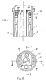
- Figure 2 is a partial cross-section of same, on plane II-II indicated in the preceding figure.
- Figure 3 is a horizontal cross-section on plane III-III indicated in both figure 1 and figure 2.
- Figure 4 is a vertical cross-section of a pressurizer used, according to the invention, in conjunction with the pressurized metal container, and which also acts as an auxiliary cooler.
- Figure 5 is a preferred embodiment of the pipes crossing through the core grid.
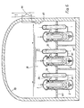
- Figure 6 shows a pool in which, according to the invention, several modular reactors are immersed.
- With specific reference to these figures: 1 indicates a pressurized metal container inside which the
vessel 2 of the nuclear reactor is contained; inside thevessel 2, the reactor has acore 4, alower input header 5, and anupper output header 6. - In the preferred solution illustrated in the figure, the
ceiling 8 of thevessel 2 has a cup-shaped structure 7 which defines, inside thevessel 2, a ring-shaped area. This ring-shaped area is split up into two concentric ring-shaped cavities reactor 4, and one acting as a downflow pipe for the same fluid. At the upper end of thedownflow pipe 10 are thecirculation pumps 11 which force the hot fluid into thedownflow pipe 10, inside which theprimary heat exchangers 3 are arranged. - The secondary fluid is fed into and extracted from the
primary exchangers 3 through insulatedpipes 12, which pass through both thevessel 2 and the pressurizedmetal container 1. - The outer wall of the
reactor vessel 2 is insulated by means of the coating 13-14, only partly shown. - Between the
metal container 1 and thereactor vessel 2 there is atank 15, filled with a neutron-absorbing liquid 16, for instance borated water; in the following description, the term "tank 15" will be used to refer indifferently to this area and to the liquid contained in it. The temperature in thetank 15 is relatively cooler than the temperature of the water contained inreactor vessel 2, thanks to the insulation 13-14 covering the outside wall of thereactor vessel 2; furthermore, the wall of the pressurizedcontainer 1 is in contact with thecold water 17 of anon-pressurized pool 18, in which the container is immersed (see figure 6). - The lower end of the
reactor vessel 2 is penetrated bymany pipes 20, for free communication between thelower header 5 and thetank 15. These pipes preferably have an elongated shape, so as to maintain a separating interface (I1) between the liquid in thetank 15 and the liquid in thelower header 5, with no widespread mixing of the two liquids. Maintenance of the I1 interface is ensured by the equal pressures, as was already the case for the Canadian patent mentioned above, and as will be explained again below. - A second series of
passages 21 is arranged between theupper header 6 and the upper part of thetank 15. At the top, thesepipes 21 lead into an annularshaped bell 22, and at the bottom into the upper part of thetank 15. The annularshaped bell 22 does not necessarily extend for the whole circumference of thereactor vessel 2. The top part of the bell may contain a gas or steam under pressure, or, as explained below, an interface (I2) may be established by means ofpipes 21 between the hot liquid contained invessel 2 and the cold liquid contained, around the latter, in thetank 15, thanks to the different temperatures of the two fluids. - This interface (I2) may be established, together with interface (I1), if the delivery rate of the
circulation pumps 11 is such that the pressure drop of the primary fluid in passing through the reactor core is equal to the difference in static head between the column of hot fluid contained invessel 2 and the column of cold fluid contained in thetank 15, measured in height between interfaces (I1) and (I2). - According to the invention, pressurizing of
container 1 may be achieved by means of the pressurizer illustrated in figure 4. This consists of anelongated shell 30, closed at the ends byconvex bottoms vertical pipes 34, dividing the pressurizer into a hotupper area 35 and a coldlower area 36. The hot area may be created in any expedient manner, for example by using a source of heat to generate asteam cushion 37. Since thepressurizer 30 is immersed in the cold water of thepool 18, the wall of the shell surrounding thehot area 35 is equipped withinsulation 38. - A
pipe 39 coming out of thepressurizer 30 immediately below thehot area 35 connects the top part of the cold area with the upper area of thetank 15. A secondlower pipe 40 connects the bottom of thepressurizer 30 to the lower area of thetank 15.Pipes cold area 36 may be equipped with a liquid-liquid heat-exchanger 41, submerged in the cold water of thepool 18. The purpose of this exchanger is to increase the heat-exchanging surface of the pressurizer wall. If necessary, liquid-liquid heat-exchangers 43 andliquid gas 44 allow natural cooling of thepool 18, by giving up heat into the surrounding ambient air. - Obviously both the various pressurized
containers 1 and thepressurizers 30 will be supported by structural elements, schematically illustrated in figures 4 and 6 and indicated as 42. - Figure 5 illustrates a special form of the channels passing through the grid of the core: each pipe has a lower converging
portion 51, aneck 52 which creates a Venturi-type effect, and an upper portion with an increasing cross-section. Theneck 52 is linked by apipe 54 to the area 16. In this case thepipes 54 replace thepipes 20 for hydraulic connection between the cold area 16 and thehot area 5, throughpipes 51. This configuration, as explained below, allows the pressure drop in the core to be increased for the same difference in static head between the cold column and the hot column. - To complete the above description, according to this invention it is possible to distinguish between a normally hot primary circuit and a normally cold fluid, contained in the
tank 15, kept cold by the exchange of heat with the fluid contained in thepool 18. - As already described, during normal operation of the system there is no appreciable circulation through the natural circulation circuit. This can be achieved by interlocking the circulation pumps 11 with the function of keeping the interface level between the cold water and the hot water in one of the two
pipes lower pipes 20 are in this case used to compensate the density variations in the primary fluid, as explained below. - According to this invention, the
container 1 must be kept pressurized by means of a pressurizing system provided for this specific purpose. According to the form of embodiment illustrated, this system is implemented by means of thepressurizer 30, the upper area of which forms a hot water plenum, while thelower area 30 is simply a cold water plenum. -
Pipes pressurized container 1 lead to thecold area 36, so that as a result of density fluctuations in the fluid insidecontainer 1, cold water is transferred betweencontainer 1 and the pressurizer 30 (fig. 4), avoiding thermal shocks on the various structures under pressure. The funnel-shaped device indicated as 33 in figure 4 produces cooling of the hot water, and then mixing of the hot water with the cold water below it if the level of the hot water drops, and it is therefore capable of reducing the heat gradient on the outer wall of the pressurizer 30 during transient phenomena. Thepipes 34 further cool the hot water during transient phenomena corresponding to drops in the level. - In the preferred embodiment of the
external pressurizer 30 hydraulically connected to the water of thevessel 15, the flow rate of the water throughpipes tank 15 and in the water of the primary circuit of thevessel 2. A change in density of the primary circuit water, due for example to a change in the output temperature from the steam generators as a consequence of a different steam demand by the control system, thus entails a change in the level of the hot-cold interface (I1) in thepipes 20. The capacity of thepipes 20 will therefore be suitably sized so as to avoid unwanted entry of borated water into the primary circuit during normal transient phenomena. Suitable auxiliary systems not part of the plant's safety system will re-establish the correct level of the hot-cold interface (I1) (for example by injecting non-borated water into the primary circuit.) - In some accidental transient phenomena, such as if a steam pipe bursts, the rapidity and the extent of the transient heat phenomenon may generate changes in the density of the water in the primary circuit which cannot be compensated by the change in level of the hot-cold front of the connections 20: this benefits safety since any entry of borated water into the primary circuit facilities quenching of the reactor.
- According to this invention, safety of the reactor is guaranteed in all conditions without intervention of an automatic nature or by an operator. Indeed, according to this invention, safety of the reactor is ensured by the entry of borated water (15) into the primary circuit each time there is a significant imbalance between the power produced and the power extracted, and each time the recirculation pumps stop.
- Removal of the residual heat takes place by a mixing of the primary circuit water with the water of the tank (15), and thus by transmission of the heat to the
pool 18 through the wall ofcontainer 1,pipes pressurizer 30. Indeed, if the pressurizer has at least two pipes connecting it to thereactor container 1, a naturally circulating flow rate may be established which can transfer heat from the reactor to the cold part of the pressurizer. The thermal capacity of the water in the pool is sufficiently high to absorb the heat produced over several days by all the modules without reaching a temperature of 100°C, and therefore without exerting pressure on thewall 19 surrounding thepool 18. - The temperature of the water in the pool will in any case be kept indefinitely at a temperature below 100°C by cooling with one or more secondary circuits consisting of a circuit of water circulating naturally between the hot source consisting of a water-water exchanger (43) submerged in the pool and the cold source consisting of a water-air exchanger (44) located outside the containment system, on a higher level than the first exchanger. The water-air exchanger, which also operates by natural circulation of air, may be of the type claimed under Italian patent no. 1159163, originally envisaged for exchanges between liquid metals and air.
- The solution put forward also envisages the possibility of guaranteeing cooling of the core without the intervention of active systems even in the event of breakage of the pressure boundary, whether this occurs at a higher or lower level than the core.
- During the first emptying phase, the two volumes of cold water located one in the upper part of
container 1 and the other in the lower part of the pressurizer 30 work together to depressurize the system and to keep the core flooded with cold water (at least one of the volumes intervenes, depending on the place of the breakage). - During the second phase of the transient phenomenon, when the level of the water inside the container tends to stabilize, the steam produced by the boiling of the water of the core condenses on the cold parts of the pressure boundary, allowing progressive filling of the latter with water from the pool through the actual crack, by means of the motive force created by the head of water in the pool.
- The exchanging surface of the pressure boundary, that is to say of the
system additional exchangers 41, communicating hydraulically with the water in the tank and in any case immersed in thepool 18. The outflow of hot water and steam during the first stage of emptying (apart from a partial condensation when passing through the cold water head of the pool) may cause initial pressurizing of theceiling 19 of thepool 18, which is reduced in time, however, due to interruption of the flow of steam and due to condensation of the steam on the cold surfaces and on the free surface of the water in the pool. The suitably shaped cup-type structure 7 serves to limit the quantity of hot water present in the primary circuit. Indeed, this insulated structure allows a sufficient quantity of cold water to be maintained inside it, in communication at the top, with the water intank 15; convection phenomena ensure that it mixes with the latter and that the heat is removed by dissipation through the insulation 13. Thisstructure 7 may also be used to support the core instruments and possibly control rods for the core. - To change the fuel, the
structure 7 has to be removed, after removing the lid of the container (1). The loading/unloading machine may then be introduced. Without having to use the gas cushion in the naturally circulating closed circuit, the moving agent consists of the static pressure differential already defined above. - During the system heating transient, when the static pressure differential due to the different densities of the hot and cold water is not significant, gas may be introduced into the bell (22), as envisaged in the known solution referred to above; during normal operation, the gas may be removed, leaving the natural circulation path (15, 20, 4, 9, 21, 15) perfectly free. During normal operation, this difference in pressure must equal the pressure drop in the core and in the ouput header; this relationship must be kept in mind in designing the core.
- According to a variant of this invention, a Venturi-type narrower cross-section is shaped into the fuel-element feed grid. The
main pipe 50 communicates at the bottom with theheader 5, while one ormore pipes 54 allow the narrower cross-section of thepipe 50 to com municate with thepassages 20. With this device a pressure drop in the core which, added to the pressure drop in theheader 9, is greater than said static pressure differential pressure is possible without recirculation through theorifice 20. - According to the invention, the solution suggested is particularly suitable for modular systems; the modules (1, 2, 30), may be almost completely shop assembled, and fitted on site into a
pool 18, the number of modules varying depending on the power output required. The simplicity of the small number of auxiliary systems required drastically reduces the on-site activities required for plants known up to now. - Finally, it must be pointed out that unlike the Canadian patent cited above, according to this invention only the limited quantity of cold and borated water in the
tank 15 has to be kept under pressure: the heat may be transmitted to a large quantity of cold water contained in thepool 18, with no need for any manual or automatic intervention.
This system means that the core may be cooled using only built-in and passive systems.
More generally speaking, according to this invention the reactor module may or may not be equipped with a steam generator having spiral, straight or U-shaped pipes and so on. If it is not, the steam may be produced directly by the core (boiling reactor).
Claims (15)
- a reactor vessel,
- a pressurized container surrounding the reactor vessel and which defines a tank full of a cold neutron-absorbing liquid,
- pipes for free communication between said pressurized container and said vessel,
in which the pressure drop in the primary fluid across the core is substantially equal to the difference in head between the cold column of said tank and the hot column of the vessel,
characterized by the fact that said pressurized container is immersed in a pool containing a neutron-absorbing liquid at atmospheric pressure and in which said reactor vessel is insulated while said pressurized container has no insulation.
- a reactor vessel equipped with a core, a lower header and an upper header, at least one heat exchanger with a secondary fluid, means for connecting hydrauli cally said headers and said heat exchanger and at least one circulation pump,
- a pressurized container surrounding the reactor vessel and which defines a tank full of a cold, neutron-absorbing liquid,
- pipes for communication between the lower area of said tank and the lower header of the vessel, as well as pipes for communication between the upper area of said tank and the upper header, in which the pressure drop in the primary fluid across the core is substantially equal to the difference in head between the cold column of said tank and the hot column of the vessel,
characterized by the fact that said pressurized container is submerged in a pool containing a neutron-absorbing liquid at atmospheric pressure.
Applications Claiming Priority (2)
| Application Number | Priority Date | Filing Date | Title |
|---|---|---|---|
| IT1254588 | 1988-09-15 | ||
| IT8812545A IT1225690B (en) | 1988-09-15 | 1988-09-15 | INTRINSICALLY SAFE NUCLEAR REACTOR OF THE PRESSURE WATER TYPE |
Publications (3)
| Publication Number | Publication Date |
|---|---|
| EP0359716A2 true EP0359716A2 (en) | 1990-03-21 |
| EP0359716A3 EP0359716A3 (en) | 1990-08-22 |
| EP0359716B1 EP0359716B1 (en) | 1996-03-06 |
Family
ID=11141416
Family Applications (1)
| Application Number | Title | Priority Date | Filing Date |
|---|---|---|---|
| EP89830374A Expired - Lifetime EP0359716B1 (en) | 1988-09-15 | 1989-09-05 | Intrinsic-safety nuclear reactor of the pressurized water type |
Country Status (9)
| Country | Link |
|---|---|
| US (1) | US5112569A (en) |
| EP (1) | EP0359716B1 (en) |
| JP (1) | JP2846897B2 (en) |
| AT (1) | ATE135132T1 (en) |
| CA (1) | CA1318042C (en) |
| DE (2) | DE359716T1 (en) |
| ES (1) | ES2015839T3 (en) |
| IT (1) | IT1225690B (en) |
| RU (1) | RU2078384C1 (en) |
Cited By (9)
| Publication number | Priority date | Publication date | Assignee | Title |
|---|---|---|---|---|
| EP0503552A1 (en) * | 1991-03-11 | 1992-09-16 | Abb Atom Ab | Shut-down system for nuclear water reactor |
| EP0526773A1 (en) * | 1991-07-30 | 1993-02-10 | FINMECCANICA S.p.A. AZIENDA ANSALDO | Pressurising apparatus for pressure vessels |
| EP0527354A1 (en) * | 1991-08-14 | 1993-02-17 | FINMECCANICA S.p.A. AZIENDA ANSALDO | Pressurised water nuclear reactor with inherent safety |
| FR2716567A1 (en) * | 1994-02-23 | 1995-08-25 | Drean Henri Louis Marie | Safety and cooling injection system for PWR |
| EP0677851A1 (en) * | 1994-04-13 | 1995-10-18 | FINMECCANICA S.p.A. AZIENDA ANSALDO | A condenser for steam mixed with non-condensable gases, operating with natural circulation, for nuclear reactor protection systems |
| WO2002073625A3 (en) * | 2001-03-09 | 2002-11-14 | Westinghouse Electric Corp | Integral pwr with diverse emergency cooling and method of operating same |
| WO2009097034A3 (en) * | 2007-11-15 | 2009-12-10 | The State Of Oregon Acting By And Through The State System Of Higher Education On Behalf Of Oregon State University | Passive emergency feedwater system for a nuclear reactor |
| US9984777B2 (en) | 2007-11-15 | 2018-05-29 | Nuscale Power, Llc | Passive emergency feedwater system |
| US12211627B2 (en) | 2007-11-15 | 2025-01-28 | Nuscale Power, Llc | Evacuated containment vessel for nuclear reactor |
Families Citing this family (20)
| Publication number | Priority date | Publication date | Assignee | Title |
|---|---|---|---|---|
| DE59912395D1 (en) * | 1998-02-03 | 2005-09-15 | Framatome Anp Gmbh | PRESSURE MEMORY AND METHOD FOR PROVIDING A PRESSURE-BASED FLUID |
| US6327323B1 (en) * | 1998-04-17 | 2001-12-04 | Westinghouse Electric Company Llc | Multiple reactor containment building |
| JP3906653B2 (en) | 2000-07-18 | 2007-04-18 | ソニー株式会社 | Image display device and manufacturing method thereof |
| JP4649745B2 (en) | 2001-02-01 | 2011-03-16 | ソニー株式会社 | Light-emitting element transfer method |
| WO2002084631A1 (en) | 2001-04-11 | 2002-10-24 | Sony Corporation | Element transfer method, element arrangmenet method using the same, and image display apparatus production method |
| JP2003045901A (en) | 2001-08-01 | 2003-02-14 | Sony Corp | Element transfer method, element arrangement method using the same, and image display device manufacturing method |
| JP3682584B2 (en) | 2001-08-06 | 2005-08-10 | ソニー株式会社 | Method for mounting light emitting element and method for manufacturing image display device |
| JP3597165B2 (en) * | 2001-11-16 | 2004-12-02 | 核燃料サイクル開発機構 | Reactor vessel thermal load mitigation device |
| RU2225045C2 (en) * | 2002-05-16 | 2004-02-27 | Опытное Конструкторское Бюро "Гидропресс" | Nuclear steam generating unit |
| FR2855310B1 (en) * | 2003-02-04 | 2008-06-13 | Michel Emin | NUCLEAR REACTOR AND ITS MEANS OF INSERTION OF LIQUID NEUTROPHAGE IN THE HEART |
| FR2887618B1 (en) * | 2005-06-27 | 2007-09-14 | Framatome Anp Sas | HEAT EXCHANGE ASSEMBLY, IN PARTICULAR FOR A NUCLEAR REACTOR |
| JP4769203B2 (en) * | 2007-01-15 | 2011-09-07 | 黒崎播磨株式会社 | Mold for molding |
| US8638901B2 (en) * | 2010-12-29 | 2014-01-28 | Westinghouse Electric Company Llc | Optimum configuration for fast reactors |
| US8867689B2 (en) * | 2011-02-15 | 2014-10-21 | Nuscale Power, Llc | Heat removal system and method for use with a nuclear reactor |
| US8867690B2 (en) * | 2011-08-25 | 2014-10-21 | Babcock & Wilcox Mpower, Inc. | Pressurized water reactor with compact passive safety systems |
| KR101513139B1 (en) * | 2013-11-28 | 2015-04-17 | 한국원자력연구원 | Reactor coolant pump and nuclear reactor plant system having the same |
| KR101529529B1 (en) * | 2013-12-03 | 2015-06-18 | 한국원자력연구원 | Passive containment cooling system and nuclear power plant having the same |
| KR101456170B1 (en) * | 2014-02-27 | 2014-10-31 | 한국원자력연구원 | Passive containment air cooling device and system with isolated pressure boundary |
| RU2745348C1 (en) * | 2019-12-31 | 2021-03-24 | Акционерное общество "АКМЭ-инжиниринг" (сокращенно АО "АКМЭ-инжиниринг") | Integral nuclear reactor (options) |
| FR3143825A1 (en) * | 2022-12-20 | 2024-06-21 | Commissariat A L'energie Atomique Et Aux Energies Alternatives | Nuclear installation comprising at least one modular nuclear reactor (SMR) and a vessel well delimiting a water basin in which the SMR reactor block is immersed. |
Family Cites Families (12)
| Publication number | Priority date | Publication date | Assignee | Title |
|---|---|---|---|---|
| NL301607A (en) * | 1962-12-12 | |||
| US3494828A (en) * | 1967-12-18 | 1970-02-10 | Stone & Webster Eng Corp | Nuclear reactor direct pressure suppression containment |
| US3718539A (en) * | 1971-03-31 | 1973-02-27 | Combustion Eng | Passive nuclear reactor safeguard system |
| US3941187A (en) * | 1971-07-14 | 1976-03-02 | The Babcock & Wilcox Company | Consolidated nuclear steam generator |
| SE391058B (en) * | 1975-06-10 | 1977-01-31 | Asea Atom Ab | LIGHT WATER COOLED REACTOR FACILITATED IN A WATER-FILLED POOL |
| SE428611B (en) * | 1979-12-17 | 1983-07-11 | Asea Atom Ab | COOLING WATER REACTOR REQUIRER |
| SE435432B (en) * | 1981-03-30 | 1984-09-24 | Asea Atom Ab | Nuclear reactor plant with gas cushions that delimits between the cooling water and the surrounding pool water |
| SE8401711L (en) * | 1984-03-28 | 1985-09-29 | Asea Atom Ab | PRESSURE WATER REACTOR CONTAINING A PRESSURE POOL |
| CH664037A5 (en) * | 1984-07-17 | 1988-01-29 | Sulzer Ag | SYSTEM WITH A NUCLEAR HEATING REACTOR. |
| US4759899A (en) * | 1984-08-29 | 1988-07-26 | Ga Technologies Inc. | Reactor with natural convection backup cooling system |
| FR2599179B1 (en) * | 1986-05-22 | 1988-07-22 | Commissariat Energie Atomique | SMALL NUCLEAR REACTOR WITH PRESSURIZED WATER AND NATURAL CIRCULATION |
| US4702879A (en) * | 1986-06-11 | 1987-10-27 | Westinghouse Electric Corp. | Nuclear reactor with passive safety system |
-
1988
- 1988-09-15 IT IT8812545A patent/IT1225690B/en active
-
1989
- 1989-08-24 CA CA000609323A patent/CA1318042C/en not_active Expired - Fee Related
- 1989-09-05 ES ES89830374T patent/ES2015839T3/en not_active Expired - Lifetime
- 1989-09-05 AT AT89830374T patent/ATE135132T1/en not_active IP Right Cessation
- 1989-09-05 EP EP89830374A patent/EP0359716B1/en not_active Expired - Lifetime
- 1989-09-05 DE DE198989830374T patent/DE359716T1/en active Pending
- 1989-09-05 DE DE68925855T patent/DE68925855T2/en not_active Expired - Fee Related
- 1989-09-13 JP JP1235898A patent/JP2846897B2/en not_active Expired - Fee Related
- 1989-09-14 RU SU894614945A patent/RU2078384C1/en active
- 1989-09-15 US US07/407,661 patent/US5112569A/en not_active Expired - Fee Related
Cited By (15)
| Publication number | Priority date | Publication date | Assignee | Title |
|---|---|---|---|---|
| EP0503552A1 (en) * | 1991-03-11 | 1992-09-16 | Abb Atom Ab | Shut-down system for nuclear water reactor |
| EP0526773A1 (en) * | 1991-07-30 | 1993-02-10 | FINMECCANICA S.p.A. AZIENDA ANSALDO | Pressurising apparatus for pressure vessels |
| EP0527354A1 (en) * | 1991-08-14 | 1993-02-17 | FINMECCANICA S.p.A. AZIENDA ANSALDO | Pressurised water nuclear reactor with inherent safety |
| FR2716567A1 (en) * | 1994-02-23 | 1995-08-25 | Drean Henri Louis Marie | Safety and cooling injection system for PWR |
| EP0677851A1 (en) * | 1994-04-13 | 1995-10-18 | FINMECCANICA S.p.A. AZIENDA ANSALDO | A condenser for steam mixed with non-condensable gases, operating with natural circulation, for nuclear reactor protection systems |
| WO2002073625A3 (en) * | 2001-03-09 | 2002-11-14 | Westinghouse Electric Corp | Integral pwr with diverse emergency cooling and method of operating same |
| WO2009097034A3 (en) * | 2007-11-15 | 2009-12-10 | The State Of Oregon Acting By And Through The State System Of Higher Education On Behalf Of Oregon State University | Passive emergency feedwater system for a nuclear reactor |
| CN101999149A (en) * | 2007-11-15 | 2011-03-30 | 由俄勒冈州高等教育管理委员会代表的俄勒冈州立大学 | Passive emergency water supply system for nuclear reactors |
| US8170173B2 (en) | 2007-11-15 | 2012-05-01 | The State Of Oregon Acting By And Through The State Board Of Higher Education On Behalf Of Oregon State University | Passive emergency feedwater system |
| KR101215323B1 (en) * | 2007-11-15 | 2013-01-21 | 더 스테이트 오브 오레곤 액팅 바이 앤드 쓰루 더 스테이트 보드 오브 하이어 에쥬케이션 온 비해프 오브 오레곤 스테이트 유니버시티 | A nuclear reactor assembly including a nuclear reactor, an emergency cooling system for the nuclear reactor, and an emergency cooling method of the nuclear reactor |
| CN101999149B (en) * | 2007-11-15 | 2013-06-19 | 由俄勒冈州高等教育管理委员会代表的俄勒冈州立大学 | Passive emergency water supply system for nuclear reactors |
| US8731130B2 (en) | 2007-11-15 | 2014-05-20 | The State Of Oregon Acting By And Through The State Board Of Higher Education On Behalf Of Oregon State University | Passive emergency feedwater system |
| US9984777B2 (en) | 2007-11-15 | 2018-05-29 | Nuscale Power, Llc | Passive emergency feedwater system |
| US11756698B2 (en) | 2007-11-15 | 2023-09-12 | Nuscale Power, Llc | Passive emergency feedwater system |
| US12211627B2 (en) | 2007-11-15 | 2025-01-28 | Nuscale Power, Llc | Evacuated containment vessel for nuclear reactor |
Also Published As
| Publication number | Publication date |
|---|---|
| CA1318042C (en) | 1993-05-18 |
| DE68925855D1 (en) | 1996-04-11 |
| ES2015839T3 (en) | 1996-07-16 |
| EP0359716B1 (en) | 1996-03-06 |
| DE359716T1 (en) | 1990-10-18 |
| ES2015839A4 (en) | 1990-09-16 |
| RU2078384C1 (en) | 1997-04-27 |
| IT8812545A0 (en) | 1988-09-15 |
| IT1225690B (en) | 1990-11-22 |
| JPH02114196A (en) | 1990-04-26 |
| US5112569A (en) | 1992-05-12 |
| JP2846897B2 (en) | 1999-01-13 |
| DE68925855T2 (en) | 1996-10-24 |
| EP0359716A3 (en) | 1990-08-22 |
| ATE135132T1 (en) | 1996-03-15 |
Similar Documents
| Publication | Publication Date | Title |
|---|---|---|
| EP0359716A2 (en) | Intrinsic-safety nuclear reactor of the pressurized water type | |
| EP0353867B1 (en) | Full pressure passive emergency core cooling and residual heat removal system for water cooled nuclear reactors | |
| US3151034A (en) | Consolidated nuclear steam generator arrangement | |
| US4753773A (en) | Double tube steam generator | |
| US4608224A (en) | Nuclear reactor cooled by a liquid metal | |
| US11901088B2 (en) | Method of heating primary coolant outside of primary coolant loop during a reactor startup operation | |
| EP0950248B1 (en) | Nuclear reactor with improved natural coolant circulation and method of improving the natural circulation of a coolant in a nuclear reactor | |
| KR102422303B1 (en) | Reactor with elevated heat exchanger | |
| JPH05240991A (en) | Pressuerized water reactor plant | |
| US4702879A (en) | Nuclear reactor with passive safety system | |
| US4998509A (en) | Passive heat removal from containment | |
| US4302296A (en) | Apparatus for insulating hot sodium in pool-type nuclear reactors | |
| US4600554A (en) | Secondary heat transfer circuit for a nuclear reactor cooled by a liquid metal such as sodium, as well as a steam generator particularly suitable for such a circuit | |
| US4909981A (en) | Nuclear reactor | |
| US4452182A (en) | Sodium-water type steam generators | |
| US4761261A (en) | Nuclear reactor | |
| Cinotti et al. | The inherently safe immersed system (ISIS) reactor | |
| US4859406A (en) | Reactor | |
| US4397811A (en) | Nuclear reactor with integral heat exchangers | |
| US20050069079A1 (en) | Modular reactor containment system | |
| US4519978A (en) | Secondary heat transfer circuit for a nuclear reactor | |
| US20240266083A1 (en) | Nuclear steam supply and start-up system, passively-cooled spent nuclear fuel pool system and method therefor, component cooling water system for nuclear power plant, passive reactor cooling system, steam generator for nuclear steam supply system | |
| KR102485225B1 (en) | Nuclear Reactor | |
| CN120344802A (en) | Safety condenser and nuclear reactor including the same | |
| Meseth | Natural circulation and stratification in the various passive safety systems of the SWR 1000 |
Legal Events
| Date | Code | Title | Description |
|---|---|---|---|
| PUAI | Public reference made under article 153(3) epc to a published international application that has entered the european phase |
Free format text: ORIGINAL CODE: 0009012 |
|
| AK | Designated contracting states |
Kind code of ref document: A2 Designated state(s): AT BE CH DE ES FR GB LI NL SE |
|
| PUAL | Search report despatched |
Free format text: ORIGINAL CODE: 0009013 |
|
| AK | Designated contracting states |
Kind code of ref document: A3 Designated state(s): AT BE CH DE ES FR GB LI NL SE |
|
| EL | Fr: translation of claims filed | ||
| TCAT | At: translation of patent claims filed | ||
| TCNL | Nl: translation of patent claims filed | ||
| DET | De: translation of patent claims | ||
| 17P | Request for examination filed |
Effective date: 19910214 |
|
| 17Q | First examination report despatched |
Effective date: 19930607 |
|
| RAP1 | Party data changed (applicant data changed or rights of an application transferred) |
Owner name: FINMECCANICA S.P.A. AZIENDA ANSALDO |
|
| GRAA | (expected) grant |
Free format text: ORIGINAL CODE: 0009210 |
|
| AK | Designated contracting states |
Kind code of ref document: B1 Designated state(s): AT BE CH DE ES FR GB LI NL SE |
|
| PG25 | Lapsed in a contracting state [announced via postgrant information from national office to epo] |
Ref country code: AT Effective date: 19960306 |
|
| REF | Corresponds to: |
Ref document number: 135132 Country of ref document: AT Date of ref document: 19960315 Kind code of ref document: T |
|
| REF | Corresponds to: |
Ref document number: 68925855 Country of ref document: DE Date of ref document: 19960411 |
|
| REG | Reference to a national code |
Ref country code: ES Ref legal event code: BA2A Ref document number: 2015839 Country of ref document: ES Kind code of ref document: T3 |
|
| ET | Fr: translation filed | ||
| REG | Reference to a national code |
Ref country code: CH Ref legal event code: NV Representative=s name: JACOBACCI & PERANI S.A. |
|
| REG | Reference to a national code |
Ref country code: ES Ref legal event code: FG2A Ref document number: 2015839 Country of ref document: ES Kind code of ref document: T3 |
|
| NLR4 | Nl: receipt of corrected translation in the netherlands language at the initiative of the proprietor of the patent | ||
| PLBE | No opposition filed within time limit |
Free format text: ORIGINAL CODE: 0009261 |
|
| STAA | Information on the status of an ep patent application or granted ep patent |
Free format text: STATUS: NO OPPOSITION FILED WITHIN TIME LIMIT |
|
| 26N | No opposition filed | ||
| PGFP | Annual fee paid to national office [announced via postgrant information from national office to epo] |
Ref country code: NL Payment date: 19980819 Year of fee payment: 10 |
|
| PGFP | Annual fee paid to national office [announced via postgrant information from national office to epo] |
Ref country code: ES Payment date: 19980907 Year of fee payment: 10 |
|
| PGFP | Annual fee paid to national office [announced via postgrant information from national office to epo] |
Ref country code: CH Payment date: 19990813 Year of fee payment: 11 |
|
| PGFP | Annual fee paid to national office [announced via postgrant information from national office to epo] |
Ref country code: GB Payment date: 19990818 Year of fee payment: 11 |
|
| PGFP | Annual fee paid to national office [announced via postgrant information from national office to epo] |
Ref country code: BE Payment date: 19990823 Year of fee payment: 11 |
|
| PGFP | Annual fee paid to national office [announced via postgrant information from national office to epo] |
Ref country code: DE Payment date: 19990825 Year of fee payment: 11 |
|
| PG25 | Lapsed in a contracting state [announced via postgrant information from national office to epo] |
Ref country code: ES Free format text: LAPSE BECAUSE OF NON-PAYMENT OF DUE FEES Effective date: 19990906 |
|
| PG25 | Lapsed in a contracting state [announced via postgrant information from national office to epo] |
Ref country code: NL Free format text: LAPSE BECAUSE OF NON-PAYMENT OF DUE FEES Effective date: 20000401 |
|
| NLV4 | Nl: lapsed or anulled due to non-payment of the annual fee |
Effective date: 20000401 |
|
| PG25 | Lapsed in a contracting state [announced via postgrant information from national office to epo] |
Ref country code: GB Free format text: LAPSE BECAUSE OF NON-PAYMENT OF DUE FEES Effective date: 20000905 |
|
| PG25 | Lapsed in a contracting state [announced via postgrant information from national office to epo] |
Ref country code: LI Free format text: LAPSE BECAUSE OF NON-PAYMENT OF DUE FEES Effective date: 20000930 Ref country code: CH Free format text: LAPSE BECAUSE OF NON-PAYMENT OF DUE FEES Effective date: 20000930 Ref country code: BE Free format text: LAPSE BECAUSE OF NON-PAYMENT OF DUE FEES Effective date: 20000930 |
|
| BERE | Be: lapsed |
Owner name: FINMECCANICA S.P.A. AZIENDA ANSALDO Effective date: 20000930 |
|
| GBPC | Gb: european patent ceased through non-payment of renewal fee |
Effective date: 20000905 |
|
| REG | Reference to a national code |
Ref country code: CH Ref legal event code: PL |
|
| PG25 | Lapsed in a contracting state [announced via postgrant information from national office to epo] |
Ref country code: DE Free format text: LAPSE BECAUSE OF NON-PAYMENT OF DUE FEES Effective date: 20010601 |
|
| REG | Reference to a national code |
Ref country code: FR Ref legal event code: TP |
|
| PGFP | Annual fee paid to national office [announced via postgrant information from national office to epo] |
Ref country code: SE Payment date: 20020731 Year of fee payment: 14 |
|
| PG25 | Lapsed in a contracting state [announced via postgrant information from national office to epo] |
Ref country code: SE Free format text: LAPSE BECAUSE OF NON-PAYMENT OF DUE FEES Effective date: 20030906 |
|
| PGFP | Annual fee paid to national office [announced via postgrant information from national office to epo] |
Ref country code: FR Payment date: 20030930 Year of fee payment: 15 |
|
| REG | Reference to a national code |
Ref country code: ES Ref legal event code: FD2A Effective date: 20001013 |
|
| EUG | Se: european patent has lapsed | ||
| PG25 | Lapsed in a contracting state [announced via postgrant information from national office to epo] |
Ref country code: FR Free format text: LAPSE BECAUSE OF NON-PAYMENT OF DUE FEES Effective date: 20050531 |
|
| REG | Reference to a national code |
Ref country code: FR Ref legal event code: ST |