EP0359206A1 - Liver function testing apparatus - Google Patents
Liver function testing apparatus Download PDFInfo
- Publication number
- EP0359206A1 EP0359206A1 EP89116878A EP89116878A EP0359206A1 EP 0359206 A1 EP0359206 A1 EP 0359206A1 EP 89116878 A EP89116878 A EP 89116878A EP 89116878 A EP89116878 A EP 89116878A EP 0359206 A1 EP0359206 A1 EP 0359206A1
- Authority
- EP
- European Patent Office
- Prior art keywords
- light
- specific dye
- δlogt1
- δlogt2
- blood
- Prior art date
- Legal status (The legal status is an assumption and is not a legal conclusion. Google has not performed a legal analysis and makes no representation as to the accuracy of the status listed.)
- Granted
Links
- 238000012360 testing method Methods 0.000 title claims abstract description 16
- 230000003908 liver function Effects 0.000 title claims abstract description 12
- 230000008034 disappearance Effects 0.000 claims abstract description 28
- 210000004369 blood Anatomy 0.000 claims abstract description 26
- 239000008280 blood Substances 0.000 claims abstract description 26
- 238000002347 injection Methods 0.000 claims abstract description 22
- 239000007924 injection Substances 0.000 claims abstract description 22
- 210000001519 tissue Anatomy 0.000 claims abstract description 20
- 230000003287 optical effect Effects 0.000 claims abstract description 17
- 210000002381 plasma Anatomy 0.000 claims abstract description 17
- 230000014759 maintenance of location Effects 0.000 claims abstract description 16
- 230000014509 gene expression Effects 0.000 claims abstract description 13
- 230000006870 function Effects 0.000 claims abstract description 8
- 238000004088 simulation Methods 0.000 claims abstract description 6
- 210000004185 liver Anatomy 0.000 claims description 4
- 238000005259 measurement Methods 0.000 description 19
- 238000000034 method Methods 0.000 description 15
- 238000010241 blood sampling Methods 0.000 description 11
- 238000002835 absorbance Methods 0.000 description 7
- 230000010349 pulsation Effects 0.000 description 5
- 238000010521 absorption reaction Methods 0.000 description 4
- 230000017531 blood circulation Effects 0.000 description 4
- 238000006243 chemical reaction Methods 0.000 description 4
- 238000010586 diagram Methods 0.000 description 4
- 238000012545 processing Methods 0.000 description 3
- 230000003321 amplification Effects 0.000 description 2
- 230000000747 cardiac effect Effects 0.000 description 2
- 230000009545 invasion Effects 0.000 description 2
- 238000003199 nucleic acid amplification method Methods 0.000 description 2
- 230000035945 sensitivity Effects 0.000 description 2
- 210000002966 serum Anatomy 0.000 description 2
- 210000003462 vein Anatomy 0.000 description 2
- 102100022907 Acrosin-binding protein Human genes 0.000 description 1
- 238000012935 Averaging Methods 0.000 description 1
- 208000007536 Thrombosis Diseases 0.000 description 1
- QVGXLLKOCUKJST-UHFFFAOYSA-N atomic oxygen Chemical compound [O] QVGXLLKOCUKJST-UHFFFAOYSA-N 0.000 description 1
- 210000004204 blood vessel Anatomy 0.000 description 1
- 238000011088 calibration curve Methods 0.000 description 1
- 230000015271 coagulation Effects 0.000 description 1
- 238000005345 coagulation Methods 0.000 description 1
- MOFVSTNWEDAEEK-UHFFFAOYSA-M indocyanine green Chemical compound [Na+].[O-]S(=O)(=O)CCCCN1C2=CC=C3C=CC=CC3=C2C(C)(C)C1=CC=CC=CC=CC1=[N+](CCCCS([O-])(=O)=O)C2=CC=C(C=CC=C3)C3=C2C1(C)C MOFVSTNWEDAEEK-UHFFFAOYSA-M 0.000 description 1
- 229960004657 indocyanine green Drugs 0.000 description 1
- 230000003340 mental effect Effects 0.000 description 1
- 229910052760 oxygen Inorganic materials 0.000 description 1
- 239000001301 oxygen Substances 0.000 description 1
- 238000000611 regression analysis Methods 0.000 description 1
- 239000012266 salt solution Substances 0.000 description 1
- 230000001629 suppression Effects 0.000 description 1
Images

Classifications
-
- G—PHYSICS
- G01—MEASURING; TESTING
- G01N—INVESTIGATING OR ANALYSING MATERIALS BY DETERMINING THEIR CHEMICAL OR PHYSICAL PROPERTIES
- G01N21/00—Investigating or analysing materials by the use of optical means, i.e. using sub-millimetre waves, infrared, visible or ultraviolet light
- G01N21/17—Systems in which incident light is modified in accordance with the properties of the material investigated
- G01N21/25—Colour; Spectral properties, i.e. comparison of effect of material on the light at two or more different wavelengths or wavelength bands
-
- A—HUMAN NECESSITIES
- A61—MEDICAL OR VETERINARY SCIENCE; HYGIENE
- A61B—DIAGNOSIS; SURGERY; IDENTIFICATION
- A61B5/00—Measuring for diagnostic purposes; Identification of persons
- A61B5/42—Detecting, measuring or recording for evaluating the gastrointestinal, the endocrine or the exocrine systems
- A61B5/4222—Evaluating particular parts, e.g. particular organs
- A61B5/4244—Evaluating particular parts, e.g. particular organs liver
-
- A—HUMAN NECESSITIES
- A61—MEDICAL OR VETERINARY SCIENCE; HYGIENE
- A61B—DIAGNOSIS; SURGERY; IDENTIFICATION
- A61B5/00—Measuring for diagnostic purposes; Identification of persons
- A61B5/0059—Measuring for diagnostic purposes; Identification of persons using light, e.g. diagnosis by transillumination, diascopy, fluorescence
Definitions
- the present invention relates to a liver function testing apparatus. More specifically, it relates to a liver function testing apparatus for automatically perf orming measurement for testing/diagnosing liver function by injecting a specific dye, which is selectively taken in and removed by only the liver, into blood and measuring a blood plasma disappearance rate and a retention rate thereof.
- the blood plasma disappearance rate and the retention rate have been measured by a method of blood sampling through use of indocyanine green (hereinafter referred to as ICG) serving as a specific dye.
- ICG indocyanine green
- a tester intravenously injects ICG into an elbow vein, for example, of a testee with an injector to perform blood sampling three times after lapses of 5, 10 and 15 minutes from the injection, and separates blood serum upon coagulation of blood clot to measure absorbance at a wavelength of 805 nm through a spectrophotometer and obtain ICG concentration values in the blood serum after the lapses of 5, 10 and 15 minutes from a previously obtained calibration curve (corresponding ICG concentration in blood vs. absorbance), thereby to calculate the blood plasma disappearance rate and the retention rate from changes of the concentration values.
- ICG is dissolved in a physiological salt solution or the like.
- Japanese Patent Publication Gazette No. 58649/1985 has proposed a method of applying light through the body surface of an organism and measuring quantities of light of a wavelength having high ICG absorption sensitivity and that of a wavelength substantially having no such sensitivity, thereby to measure the blood plasma disappearance rate and the retention rate from time changes (dye disappearance curve) thereof without performing blood sampling.
- a principal object of the present invention is to provide a liver function testing apparatus which can remove artifacts such as blood flow disturbance, vibration of an organism, pulsation in the organism and changes of the blood volume in the organism caused in attachment of a sensor to the organism, to enable correct measurement.
- a sensor formed by light sources and a light receiving element is attached to a testee before injection of a specific dye, to measure values ⁇ logT1 and ⁇ logT2 corresponding to pulse wave signals obtained upon passage through a prescribed optical path in vital tissue n times.
- a value Cg corresponding to specific dye concentration in blood is operated from ⁇ 0, ⁇ logT1 and ⁇ logT2, and a function of a simulation curve in time changes of the operation result is operated through least square fitting, to output operation results of a blood plasma disappearance rate K and a T-minute retention rate R % of the specific dye on the basis of the function.
- the present invention therefore, time management of a correct specific dye disappearance curve is enabled, whereby correct data can be obtained.
- the blood plasma disappearance rate K and the T-minute retention rate R % can be obtained not from several samples prepared according to the conventional blood sampling method but from a large number of disappearance curve data, thereby to improve reliability of the data.
- the method of measurement can be further simplified as compared with the conventional testing method of obtaining the blood plasma disappearance rate K and the T-minute retention rate R % by performing measurement three times with changes of ICG dosages.
- the problematic artifacts such as blood flow disturbance, vibration of an organism, pulsation in the organism and changes of the blood volume in the organism caused upon attachment of a sensor to the organism can be removed, to enable correct measurement.
- the present invention is effectively applicable to the overall field of measuring a dye in an organism with no invasion.
- K operation value t: elapsed time (min.) after injection of specific dye A
- B constants
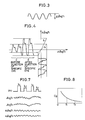
- Fig. 2 illustrates incident light which is applied to vital tissue and transmitted light
- Fig. 3 illustrates changes in quantity of light corresponding to a pulse wave
- Fig. 4 illustrates changes of ⁇ logT1 and ⁇ logT2 expressed on x and y coordinates.
- absorbance A is expressed as logI t /I in , assuming that I t represents the quantity of transmitted light.
- the organism is formed by a tissue layer and a blood layer as shown in Fig. 2, and the blood layer is formed by an arterial layer and a venous layer.
- the thickness of the arterial layer is changed by ⁇ D in response to pulsation (pulse wave) of the heart.
- the quantity I t of the transmitted light is varied with this change. Therefore, the absorbance A is similarly changed by ⁇ A.
- ⁇ A ⁇ logI t (1)
- ⁇ A1 and ⁇ A2 represent changes of absorption quantities caused by pulse waves of a wavelength ⁇ 1 largely absorbed by a specific dye and an unabsorbed wavelength ⁇ 2
- ⁇ A1 (E ⁇ 1 ⁇ C ⁇ + E g 1 ⁇ °C g ) ⁇ D
- ⁇ A2 E ⁇ 2* ⁇ C ⁇ ⁇ D (3)
- E ⁇ i absorption coefficient of blood at wavelength ⁇ i
- E g i absorption coefficient of ICG at wavelength ⁇ i C ⁇ : blood concentration
- C g specific dye concentration
- ⁇ D change in thickness of blood layer
- the specific dye concentration C g in the blood can be evaluated by obtaining ⁇ A1/ ⁇ A2 after injection of the specific dye.
- the expression (8) may be solved to obtain ⁇ before injection of the specific dye and the expression (8) may be solved after injection of the specific dye, while Cg may be evaluated from the expression (6).
- ⁇ logT1 difference between peaks of changes in quantity of light corresponding to a pulse wave has been regarded as ⁇ logT1, as shown in Fig. 3.
- this method can only prepare a sample corresponding to the cardiac cycle, and the above ⁇ logT1 has been obtained by performing measurement several times and averaging the results in the actual circumstances.
- ⁇ logT1 is set on the y-axis and ⁇ logT2 is set on the x-axis as shown in Fig. 4, for example, so that changes of measured values are as shown in Fig. 4 respectively and move on the coordinates with inclination expressed by a straight line a before injection of the specific dye.
- This inclination is ⁇ 0 shown in the expression (6).
- absorbance of ⁇ 1 is changed to define a waveform corresponding to a pulse wave such as a, and the inclination is changed to define a straight line such as a.
- This inclination ⁇ is ⁇ A1/ ⁇ A2 in the expression (6).
- inclination ⁇ (t) can be accurately calculated by increasing the number of measurement samples of ⁇ logT1 and ⁇ logT2, thereby to enable comprehension of concentration changes of the specific dye at a high speed without depending on the cardiac cycle.
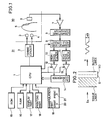
- Fig. 1 is a schematic block diagram showing an embodiment of the present invention.
- a liver function testing apparatus is formed by a sensor part 30 and a measurement processing part 31.
- the sensor part 30 includes a first light source 3, a second light source 4 and a light receiving element 6.
- the first light source 3 and the second light source 4 generate optical pulses of the wavelength ⁇ having large absorbance with respect to the specific dye and the wavelength ⁇ 2 having no such absorbance.
- the light receiving element 6 receives light beams, which are applied from the light sources 3 and 4 to vital tissue 5 to pass through a prescribed optical path.
- the light sources 3 and 4 are controlled by a timing circuit 2 on the basis of a command from a CPU 1 which is provided in the measurement processing part 31, to alternately generate the light beams in pulse operation.
- the CPU 1 included in the measurement processing part 31 serves as arithmetic means. As hereinabove described, the CPU 1 supplies prescribed pulses to the light sources 3 and 4 through the timing circuit 2. The light beams emitted from the first and second light sources 3 and 4 pass through the prescribed optical path in the vital tissue 5 to be incident upon the light receiving element 6. A current generated from the light receiving element 6 is subjected to current-voltage conversion and amplified by an amplifier 7. The amplified signal is supplied to a logarithmic converter 8 to be subjected to logarithmic conversion, and supplied to a sample-and-hold circuit 9, to be separated into signals of the wavelengths ⁇ 1 and ⁇ 2. The separated respective signals of the wavelengths ⁇ 1 and ⁇ 2 are supplied to high-pass filters 10 and 11.
- These signals include components by pulse waves as well as changes of blood volume such as those in venous blood, to have large snaking components. Therefore, the high-pass filters 10 and 11 remove these components to output only pulsating components, which in turn are supplied to an A-D converter 14 through amplifiers 12 and 13.
- the amplifiers 12 and 13 are so controlled that amplification factors thereof are changed in response to control signals from the CPU 1.
- the A-D converter 14 converts the inputted signals into digital signals and supplies the same to the CPU 1.
- the CPU 1 stores the digital signals in a RAM 16.
- the CPU 1 is connected with a ROM 15, the RAM 16, a display part 17, a printing part 18 and a manipulation part 19.
- the ROM 15 stores programs based on flow charts shown in Figs. 5 and 6 as hereinafter described.
- the manipulation part 19 includes a start key 20 and a print key 21.
- the start key 20 is adapted to command starting of a measurement mode
- the print key 21 is adapted to supply a command for printing out test results to the printing part 18.
- Figs. 5 and 6 are flow charts for illustrating concrete operation of the embodiment of the present invention
- Fig. 7 is a waveform diagram showing voltages corresponding to pulse waves
- Fig. 8 illustrates an exemplary ICG disappearance curve obtained in the case of employing ICG as the specific dye.
- step SP1 shown in Fig. 5 power is applied to the apparatus and then quantities of light are adjusted. That is, the CPU 1 supplies a command to the timing circuit 2 to adjust driving currents for the light sources 3 and 4 respectively, while adjusting the light receiving element 6 so that its output reaches a prescribed level.
- Light beams emitted from the light sources 3 and 4 pass through a prescribed optical path in the vital tissue 5 to be incident upon the light receiving element 6, and a current generated from the light receiving element 6 is subjected to current-voltage conversion and amplified by the amplifier 7, to provide an output V PD shown in Fig. 7.
- This signal is supplied to the logarithmic converter 6 to be subjected to logarithmic conversion, and separated into signals of the waveforms ⁇ 1 and ⁇ 2 by the sample-and-hold circuit 9. These signals are expressed as logT1 and logT2 in Fig. 7 respectively.
- These signals contain components by pulse waves as well as changes in blood volume such as those in venous blood etc., to have large snaking components, which are removed by the high-pass filters 10 and 11 so that only pulsating components such as ⁇ logT1 and ⁇ logT2 shown in Fig. 7 are extracted.
- the CPU 1 controls amplification factors of the amplifiers 12 and 13 to amplify the signals until widths between peaks of pulse wave corresponding voltages of ⁇ logT1 and ⁇ logT2 shown in Fig. 7 reach certain levels. Then, the CPU 1 calculates ⁇ 0 at a step SP3.
- the CPU 1 displays indication such as "inject ICG", for example, on the display part 17 at a step SP4.
- the operator prepares to inject ICG into the vein of the organism, and turns on the start key 20 of the manipulation part 19 simultaneously with ICG injection.
- the CPU 1 waits for entry of the start key 20 at a step SP5, and operates T-minute ICG concentration Cg in blood at a step SP6 when the start key 20 is operated.
- ⁇ at a certain time t is evaluated in accordance with the aforementioned flow chart shown in Fig. 6, thereby to obtain Cg from the above expression (6), supposing that ⁇ is ⁇ A1/ ⁇ A2.
- the data of Cg draw an ICG disappearance curve as shown in Fig.
- the CPU 1 displays the disappearance curve shown in Fig. 8 and the values K and R on the display part 17, and outputs the same to the printing part 18 to print out the same at a step SP8.
- the present invention can be also applied to an apparatus for measuring R MAX by evaluating/calculating values K of various ICG dosages.
- optical pulses of a wavelength largely absorbed by a specific dye and optical pulses of a wavelength not absorbed by the same are applied to vital tissue at prescribed levels to detect optical pulses passing through a prescribed optical path in the vital tissue, and after the specific dye is injected on the basis of the outputs, a blood plasma disappearance rate and a retention rate of the specific dye are obtained on the basis of light receiving outputs from injection to a prescribed time in accordance with prescribed operation expressions.
- time management of a correct specific dye disappearance curve is enabled to obtain correct data.
- the blood plasma disappearance rate and the retention rate can be obtained not from several samples prepared by the conventional blood sampling method but from a large number of disappearance curve data, thereby to improve reliability of the data.
- the method of measurement can be further simplified as compared with the conventional testing method of obtaining the blood plasma disappearance rate and the retention rate by performing measurement several times with changes in ICG dosages.
- the present invention is effectively applicable to the overall field of measuring a dye in an organism with no invasion.
- the present invention is applicable not only to a liver function testing apparatus but to an apparatus, such as a pulse oximeter, for example, for measuring changes in concentration of a dye in an organism through pulse waves.
Landscapes
- Health & Medical Sciences (AREA)
- Life Sciences & Earth Sciences (AREA)
- Physics & Mathematics (AREA)
- General Health & Medical Sciences (AREA)
- Pathology (AREA)
- Biomedical Technology (AREA)
- Engineering & Computer Science (AREA)
- Heart & Thoracic Surgery (AREA)
- Medical Informatics (AREA)
- Molecular Biology (AREA)
- Surgery (AREA)
- Animal Behavior & Ethology (AREA)
- Biophysics (AREA)
- Public Health (AREA)
- Veterinary Medicine (AREA)
- Gastroenterology & Hepatology (AREA)
- Endocrinology (AREA)
- Physiology (AREA)
- Spectroscopy & Molecular Physics (AREA)
- Chemical & Material Sciences (AREA)
- Analytical Chemistry (AREA)
- Biochemistry (AREA)
- General Physics & Mathematics (AREA)
- Immunology (AREA)
- Measurement Of The Respiration, Hearing Ability, Form, And Blood Characteristics Of Living Organisms (AREA)
- Investigating Or Analysing Biological Materials (AREA)
- Investigating Or Analysing Materials By The Use Of Chemical Reactions (AREA)
Abstract
Description
- The present invention relates to a liver function testing apparatus. More specifically, it relates to a liver function testing apparatus for automatically perf orming measurement for testing/diagnosing liver function by injecting a specific dye, which is selectively taken in and removed by only the liver, into blood and measuring a blood plasma disappearance rate and a retention rate thereof.
- In general, the blood plasma disappearance rate and the retention rate have been measured by a method of blood sampling through use of indocyanine green (hereinafter referred to as ICG) serving as a specific dye.
- According to this method, a tester intravenously injects ICG into an elbow vein, for example, of a testee with an injector to perform blood sampling three times after lapses of 5, 10 and 15 minutes from the injection, and separates blood serum upon coagulation of blood clot to measure absorbance at a wavelength of 805 nm through a spectrophotometer and obtain ICG concentration values in the blood serum after the lapses of 5, 10 and 15 minutes from a previously obtained calibration curve (corresponding ICG concentration in blood vs. absorbance), thereby to calculate the blood plasma disappearance rate and the retention rate from changes of the concentration values. ICG is dissolved in a physiological salt solution or the like.
- Japanese Patent Publication Gazette No. 58649/1985 has proposed a method of applying light through the body surface of an organism and measuring quantities of light of a wavelength having high ICG absorption sensitivity and that of a wavelength substantially having no such sensitivity, thereby to measure the blood plasma disappearance rate and the retention rate from time changes (dye disappearance curve) thereof without performing blood sampling.
- However, although it is necessary to correctly measure the blood sampling times after injection in the conventional blood sampling method, the times have not been accurately measured in an actual test, while the operation for such measurement has been complicated. Further, the testee has been subjected to heavy mental and physical burdens by blood sampling. In an RMAX measuring method of evaluating the blood plasma disappearance rate by performing measurement several times with changes in ICG dosages, which method has been widely employed in recent years, blood sampling is performed ten or more times, to further increase the burdens on the testee.
- In the aforementioned method of performing measurement without blood sampling, which is disclosed in Japanese Patent Publication Gazette No. 58649/1985 or Japanese Patent Laying-Open Gazette No. 162934/1986, the output of a sensor actually attached to an organism is fluctuated by influences such as blood flow disturbance caused by suppression on a blood vessel, vibration of the organism, which is the object of measurement, pulsation in the organism, changes of blood volume in the organism (the blood volume is changed by merely vertically moving an arm, for example) etc., and hence a correct dye disappearance curve cannot be obtained. Thus, the blood plasma disappearance rate and the retention rate obtained by the curve cannot be recognized as being correct.
- Further, there is disclosed a method of measuring ICG concentration in blood by employing widths between peaks of changes in quantities of light beams of two wavelengths caused by pulse waves through an optical blood measuring apparatus described in Japanese Patent Laying-Open Gazette No. 128387/1975 or an oximeter described in Japanese Patent Laying-Open Gazette No. 88778/1978 as another method of performing measurement without blood sampling. However, such widths of changes in quantities of light cannot be correctly measured due to vibration of the organism etc., and it has been impossible to obtain a correct dye disappearance curve.
- Accordingly, a principal object of the present invention is to provide a liver function testing apparatus which can remove artifacts such as blood flow disturbance, vibration of an organism, pulsation in the organism and changes of the blood volume in the organism caused in attachment of a sensor to the organism, to enable correct measurement.
- Briefly stated, a sensor formed by light sources and a light receiving element is attached to a testee before injection of a specific dye, to measure values ΔlogT₁ and ΔlogT₂ corresponding to pulse wave signals obtained upon passage through a prescribed optical path in vital tissue n times. Then a value α₀ is evaluated by two-variable statistical computation as to n ΔlogT₁ and n ΔlogT₂ on the basis of an operation expression of logT₁ = α₀logT₂, and in response to decision outputs of levels of respective light beams emitted from the light sources, ΔlogT₁ and ΔogT₂ corresponding to the pulse wave signals are measured on the basis of intensity levels of first light and second light reflecting the vital tissue from injection to a prescribed time after the specific dye is injected. A value Cg corresponding to specific dye concentration in blood is operated from α₀, ΔlogT₁ and ΔlogT₂, and a function of a simulation curve in time changes of the operation result is operated through least square fitting, to output operation results of a blood plasma disappearance rate K and a T-minute retention rate R % of the specific dye on the basis of the function.
- According to the present invention, therefore, time management of a correct specific dye disappearance curve is enabled, whereby correct data can be obtained. Further, the blood plasma disappearance rate K and the T-minute retention rate R % can be obtained not from several samples prepared according to the conventional blood sampling method but from a large number of disappearance curve data, thereby to improve reliability of the data. In addition, the method of measurement can be further simplified as compared with the conventional testing method of obtaining the blood plasma disappearance rate K and the T-minute retention rate R % by performing measurement three times with changes of ICG dosages. Further, the problematic artifacts such as blood flow disturbance, vibration of an organism, pulsation in the organism and changes of the blood volume in the organism caused upon attachment of a sensor to the organism can be removed, to enable correct measurement. Thus, the present invention is effectively applicable to the overall field of measuring a dye in an organism with no invasion.
- In a more preferred embodiment of the present invention, ΔlogT₁ and ΔlogT₂ are measured m times as operation values Cg(T) assuming that ΔlogT₁ and ΔlogT₂ represent values corresponding to pulse wave signals of intensity levels of first light and second light passing through a prescribed optical path in vital tissue, and a value α(t) is evaluated as to
m x 2 by two-variable statistical computation of ΔlogT₁ = α(t)·ΔlogT₂, to obtain Cg(t) = β(α(t) - α₀). - In the preferred embodiment, further, the function Cg of the operated simulation curve is:
Cg = A·eBt
where
Cg: operation value
t: elapsed time (min.) after injection of specific dye
A, B: constants
The blood plasma disappearance rate K and the T-minute retention rate R % are obtained from:
K = -B
R % = eBt
assuming that the elapsed time after injection, which characteristically expresses intake of the specific dye in the liver, is T minutes. - These and other objects, features, aspects and advantages of the present invention will become more apparent from the following detailed description of the present invention when taken in conjunction with the accompanying drawings.
-
- Fig. 1 is a schematic block diagram showing an embodiment of the present invention;
- Fig. 2 illustrates incident light applied to an organism and transmitted light;
- Fig. 3 illustrates changes in quantity of light corresponding to a pulse wave;
- Fig. 4 illustrates changes of ΔlogT₁ and ΔlogT₂ expressed on x and y coordinates;
- Figs. 5 and are flow charts for illustrating concrete operation of the embodiment of the present invention;
- Fig. 7 is a waveform diagram showing voltages corresponding to pulse waves; and
- Fig. 8 illustrates an exemplary ICG disappearance curve.
-
- Fig. 2 illustrates incident light which is applied to vital tissue and transmitted light, Fig. 3 illustrates changes in quantity of light corresponding to a pulse wave, and Fig. 4 illustrates changes of ΔlogT₁ and ΔlogT₂ expressed on x and y coordinates.
- With reference to Figs. 2 to 4, the principle of the present invention is now described. When incident light Iin is applied to an organism as shown in Fig. 2, absorbance A is expressed as logIt/Iin, assuming that It represents the quantity of transmitted light. The organism is formed by a tissue layer and a blood layer as shown in Fig. 2, and the blood layer is formed by an arterial layer and a venous layer. The thickness of the arterial layer is changed by ΔD in response to pulsation (pulse wave) of the heart. The quantity It of the transmitted light is varied with this change. Therefore, the absorbance A is similarly changed by ΔA. Hence,
ΔA = ΔlogIt (1)
Assuming that ΔA₁ and ΔA₂ represent changes of absorption quantities caused by pulse waves of a wavelength λ₁ largely absorbed by a specific dye and an unabsorbed wavelength λ₂,
ΔA₁ = (E β¹·Cβ + Eg¹·°Cg)·ΔD (2)
ΔA₂ =E β²*·Cβ·ΔD (3)
where
Eβ i: absorption coefficient of blood at wavelength λi
Eg i: absorption coefficient of ICG at wavelength λi
Cβ: blood concentration
Cg: specific dye concentration
ΔD: change in thickness of blood layer - Assuming that the degree of oxygen saturation of the blood is constant,
E β¹·Cβ·ΔD = α₀(E β²·Cβ·ΔD) (4)
Hence , the above expression (2) is transformed as follows: ΔA₁ = K·ΔA₂ +E g¹·Cg·ΔD (5)
Thus,
Cg = (ΔA₁/ΔA₂ - α₀)·E β²/E g¹·Eβ (6) -
E β²/E g¹ is a known constant amount, and Cβ is interpreted as being constant as blood concentration. Further, K can be determined from relation between ΔA₁ and ΔA₂, since the equation (2) is expressed as:
ΔA₁ =E β¹·Cβ·ΔD (7)
before injection of the specific dye. - Hence, the specific dye concentration Cg in the blood can be evaluated by obtaining ΔA₁/ΔA₂ after injection of the specific dye.
- Assuming that T₁ and T₂ represent quantities of transmitted light having the wavelength λ₁ and that having the wavelength λ₂ while ΔT₁ and ΔT₂ represent changes thereof caused by ΔD, the following equation results from the expression (1):
ΔA₁/ΔA₂ = ΔlogT₁/ΔlogT₂ = α (8) - Hence, the expression (8) may be solved to obtain α before injection of the specific dye and the expression (8) may be solved after injection of the specific dye, while Cg may be evaluated from the expression (6). In the oximeter described in the aforementioned Japanese Patent Laying-Open Gazette No. 88778/1978 etc., difference between peaks of changes in quantity of light corresponding to a pulse wave has been regarded as ΔlogT₁, as shown in Fig. 3. However, this method can only prepare a sample corresponding to the cardiac cycle, and the above ΔlogT₁ has been obtained by performing measurement several times and averaging the results in the actual circumstances.
- According to the present invention, not the difference between the peaks is obtained but ΔlogT₁ is set on the y-axis and ΔlogT₂ is set on the x-axis as shown in Fig. 4, for example, so that changes of measured values are as shown in Fig. 4 respectively and move on the coordinates with inclination expressed by a straight line a before injection of the specific dye. This inclination is α₀ shown in the expression (6). Then, when the specific dye is injected, absorbance of λ₁ is changed to define a waveform corresponding to a pulse wave such as a, and the inclination is changed to define a straight line such as a. This inclination α is ΔA₁/ΔA₂ in the expression (6).
- Hence, inclination α(t) can be accurately calculated by increasing the number of measurement samples of ΔlogT₁ and ΔlogT₂, thereby to enable comprehension of concentration changes of the specific dye at a high speed without depending on the cardiac cycle.
- An embodiment according to this method is now described.
- Fig. 1 is a schematic block diagram showing an embodiment of the present invention. Referring to Fig. 1, a liver function testing apparatus is formed by a
sensor part 30 and ameasurement processing part 31. Thesensor part 30 includes a firstlight source 3, a secondlight source 4 and a light receiving element 6. The firstlight source 3 and the secondlight source 4 generate optical pulses of the wavelength λ having large absorbance with respect to the specific dye and the wavelength λ₂ having no such absorbance. The light receiving element 6 receives light beams, which are applied from thelight sources vital tissue 5 to pass through a prescribed optical path. Thelight sources timing circuit 2 on the basis of a command from aCPU 1 which is provided in themeasurement processing part 31, to alternately generate the light beams in pulse operation. - The
CPU 1 included in themeasurement processing part 31 serves as arithmetic means. As hereinabove described, theCPU 1 supplies prescribed pulses to thelight sources timing circuit 2. The light beams emitted from the first and secondlight sources vital tissue 5 to be incident upon the light receiving element 6. A current generated from the light receiving element 6 is subjected to current-voltage conversion and amplified by an amplifier 7. The amplified signal is supplied to alogarithmic converter 8 to be subjected to logarithmic conversion, and supplied to a sample-and-hold circuit 9, to be separated into signals of the wavelengths λ₁ and λ₂. The separated respective signals of the wavelengths λ₁ and λ₂ are supplied to high-pass filters pass filters A-D converter 14 throughamplifiers amplifiers CPU 1. TheA-D converter 14 converts the inputted signals into digital signals and supplies the same to theCPU 1. TheCPU 1 stores the digital signals in aRAM 16. - The
CPU 1 is connected with aROM 15, theRAM 16, adisplay part 17, aprinting part 18 and amanipulation part 19. TheROM 15 stores programs based on flow charts shown in Figs. 5 and 6 as hereinafter described. Themanipulation part 19 includes astart key 20 and aprint key 21. Thestart key 20 is adapted to command starting of a measurement mode, and theprint key 21 is adapted to supply a command for printing out test results to theprinting part 18. - Figs. 5 and 6 are flow charts for illustrating concrete operation of the embodiment of the present invention, Fig. 7 is a waveform diagram showing voltages corresponding to pulse waves, and Fig. 8 illustrates an exemplary ICG disappearance curve obtained in the case of employing ICG as the specific dye.
- With reference to Figs. 1 and 5 to 8, concrete operation of the embodiment of the present invention is now described as to the case of employing ICG as the specific dye. At a step SP1 shown in Fig. 5, power is applied to the apparatus and then quantities of light are adjusted. That is, the
CPU 1 supplies a command to thetiming circuit 2 to adjust driving currents for thelight sources - Light beams emitted from the
light sources vital tissue 5 to be incident upon the light receiving element 6, and a current generated from the light receiving element 6 is subjected to current-voltage conversion and amplified by the amplifier 7, to provide an output VPD shown in Fig. 7. This signal is supplied to the logarithmic converter 6 to be subjected to logarithmic conversion, and separated into signals of the waveforms λ₁ and λ₂ by the sample-and-hold circuit 9. These signals are expressed as logT₁ and logT₂ in Fig. 7 respectively. These signals contain components by pulse waves as well as changes in blood volume such as those in venous blood etc., to have large snaking components, which are removed by the high-pass filters - At a step SP2, the
CPU 1 controls amplification factors of theamplifiers CPU 1 calculates α₀ at a step SP3. In more concrete terms, theCPU 1 samples the signals of ΔlogT₁ and ΔlogT₁ n times at a step SP31 as shown in Fig. 6 and then performs regression analysis as to i = 1 to n through use of 2 x n data by an operation expression of logT₁(i) = α·logT₂(i) at a step SP32 to calculate α, and stores the same in theRAM 16 as α₀. - Then, the
CPU 1 displays indication such as "inject ICG", for example, on thedisplay part 17 at a step SP4. Thus, the operator prepares to inject ICG into the vein of the organism, and turns on thestart key 20 of themanipulation part 19 simultaneously with ICG injection. TheCPU 1 waits for entry of the start key 20 at a step SP5, and operates T-minute ICG concentration Cg in blood at a step SP6 when thestart key 20 is operated. In more concrete terms, α at a certain time t is evaluated in accordance with the aforementioned flow chart shown in Fig. 6, thereby to obtain Cg from the above expression (6), supposing that α is ΔA₁/ΔA₂. The data of Cg draw an ICG disappearance curve as shown in Fig. 8, for example, and within the data, constants A and B are evaluated through least square fitting with a simulation curve of:
Cg(I) = AeBt
t = TS/(n - 1) (min.)
with respect to data between times T₁ and T₂ (0 < T₁ < T₂ < T). - Then, the
CPU 1 operates a blood plasma disappearance rate K = -B and a T-minute retention rate R %= eBT at a step SP7, to evaluate K and R. - Then, the
CPU 1 displays the disappearance curve shown in Fig. 8 and the values K and R on thedisplay part 17, and outputs the same to theprinting part 18 to print out the same at a step SP8. - The present invention can be also applied to an apparatus for measuring RMAX by evaluating/calculating values K of various ICG dosages.
- According to the present invention, as hereinabove described, optical pulses of a wavelength largely absorbed by a specific dye and optical pulses of a wavelength not absorbed by the same are applied to vital tissue at prescribed levels to detect optical pulses passing through a prescribed optical path in the vital tissue, and after the specific dye is injected on the basis of the outputs, a blood plasma disappearance rate and a retention rate of the specific dye are obtained on the basis of light receiving outputs from injection to a prescribed time in accordance with prescribed operation expressions. Thus, time management of a correct specific dye disappearance curve is enabled to obtain correct data.
- Further, the blood plasma disappearance rate and the retention rate can be obtained not from several samples prepared by the conventional blood sampling method but from a large number of disappearance curve data, thereby to improve reliability of the data.
- In addition, the method of measurement can be further simplified as compared with the conventional testing method of obtaining the blood plasma disappearance rate and the retention rate by performing measurement several times with changes in ICG dosages.
- Further, problematic artifacts such as blood flow disturbance, vibration of an organism, pulsation in the organism and changes of the blood volume in the organism caused in attachment of a sensor to the organism can be removed to enable correct measurement. Thus, the present invention is effectively applicable to the overall field of measuring a dye in an organism with no invasion.
- The present invention is applicable not only to a liver function testing apparatus but to an apparatus, such as a pulse oximeter, for example, for measuring changes in concentration of a dye in an organism through pulse waves.
- Although the present invention has been described and illustrated in detail, it is clearly understood that the same is by way of illustration and example only and is not to be taken by way of limitation, the spirit and scope of the present invention being limited only by the terms of the appended claims.
Claims (3)
light source means (3, 4) for exposing vital tissue to first light of a wavelength absorbed by a specific dye dosed into blood of said vital tissue to be taken in and removed by the liver and second light of a wavelength not absorbed by said specific dye;
light receiving means (6) for detecting said first light and said second light from said light source means passing through a prescribed optical path in said vital tissue;
decision means (SP1) for deciding levels of said first light and said second light from said light source means in response to signals received by said light receiving means;
set means (SP1) for setting levels of said first light and said second light emitted from said light source means so that intensity levels of said first light and said second light passing through said prescribed optical path in said vital tissue upon attachment of a sensor formed by said light source means and said light receiving means to a testee are within prescribed ranges before injection of said specific dye;
set means (SP2) for logarithmically converting intensity values T₁ and T₂ of said first light and said second light passing through said prescribed optical path in said vital tissue, extracting only ΔlogT₁ and ΔlogT₂ corresponding to pulse wave signals, and setting maximum and minimum widths of said ΔlogT₁ and ΔlogT₂ within prescribed ranges before injection of said specific dye;
means (SP4) for informing timing for injecting said specific dye;
arithmetic means (SP3 to SP8) for measuring logT₁ and logT₂ corresponding to pulse wave signals obtained by passage through said prescribed optical path in said vital tissue upon attachment of said sensor formed by said light source means and said light receiving means to said testee n times to evaluate α₀ by variable statistical computation as to n ΔlogT₁ and n ΔlogT₂ on the basis of an operation expression of logT₁ = α₀logT₂ before injection of said specific dye, measuring ΔlogT₁ and ΔlogT₂ corresponding to said pulse wave signals on the basis of intensity levels of said first light and second light reflecting said vital tissue from injection to a prescribed time in response to outputs from said decision means after injection of said specific dye, operating a value Cg corresponding to specific dye concentration in blood from said α₀, ΔlogT₁ and ΔlogT₂, operating a function of a simulation curve in time changes of the result of said operation through least square fitting, and evaluating a blood plasma disappearance rate K and a T-minute retention rate R % of said specific dye on the basis of said function; and
output means (17, 18) for outputting the result of operation by said arithmetic means.
Cg(t) = β(α(t) -α₀)
where β represents a constant.
Cg = A·eBt
where
Cg: operation value
t: elapsed time (min.) after injection of specific dye
A, B: constants
said apparatus further including means for obtaining said blood plasma disappearance rate K and said T-minute retention rate R % from:
K = -B
R % = eBt
assuming that an elapsed time upon injection, which characteristically expresses intake of said specific dye in the liver, is T minutes.
Applications Claiming Priority (2)
| Application Number | Priority Date | Filing Date | Title |
|---|---|---|---|
| JP230790/88 | 1988-09-14 | ||
| JP63230790A JPH0657216B2 (en) | 1988-09-14 | 1988-09-14 | Liver function test device |
Publications (2)
| Publication Number | Publication Date |
|---|---|
| EP0359206A1 true EP0359206A1 (en) | 1990-03-21 |
| EP0359206B1 EP0359206B1 (en) | 1995-03-29 |
Family
ID=16913306
Family Applications (1)
| Application Number | Title | Priority Date | Filing Date |
|---|---|---|---|
| EP89116878A Expired - Lifetime EP0359206B1 (en) | 1988-09-14 | 1989-09-12 | Liver function testing apparatus |
Country Status (8)
| Country | Link |
|---|---|
| US (1) | US5154176A (en) |
| EP (1) | EP0359206B1 (en) |
| JP (1) | JPH0657216B2 (en) |
| KR (1) | KR910008650B1 (en) |
| CN (1) | CN1022513C (en) |
| CA (1) | CA1333097C (en) |
| DE (1) | DE68921947T2 (en) |
| RU (1) | RU2074634C1 (en) |
Cited By (6)
| Publication number | Priority date | Publication date | Assignee | Title |
|---|---|---|---|---|
| EP0399482A2 (en) * | 1989-05-24 | 1990-11-28 | Sumitomo Electric Industries, Ltd. | Liver function testing apparatus |
| WO1993005704A1 (en) * | 1991-09-13 | 1993-04-01 | Andreas Hoeft | Process and device for determining the volume of blood in circulation |
| WO1993010470A1 (en) * | 1991-11-18 | 1993-05-27 | The General Hospital Corporation | Ambulatory clearance function monitor |
| US5687726A (en) * | 1991-09-13 | 1997-11-18 | Hoeft; Andreas | Process for determining the volume of blood in circulation |
| WO2000001297A1 (en) * | 1998-07-01 | 2000-01-13 | Andreas Hoeft | Determination of liver function using the rate at which plasma disappears |
| US7074190B2 (en) * | 2002-10-09 | 2006-07-11 | Industrial Technology Research Institute | Non-invasive apparatus system for monitoring drug hepatoxicity and uses thereof |
Families Citing this family (17)
| Publication number | Priority date | Publication date | Assignee | Title |
|---|---|---|---|---|
| US5490505A (en) | 1991-03-07 | 1996-02-13 | Masimo Corporation | Signal processing apparatus |
| MX9702434A (en) | 1991-03-07 | 1998-05-31 | Masimo Corp | Signal processing apparatus. |
| JP3116252B2 (en) * | 1992-07-09 | 2000-12-11 | 日本光電工業株式会社 | Pulse oximeter |
| US5339033A (en) * | 1992-08-11 | 1994-08-16 | Alliance Pharmaceutical Corp. | Method of improving fat saturation during MRI |
| US7376453B1 (en) | 1993-10-06 | 2008-05-20 | Masimo Corporation | Signal processing apparatus |
| JP3270917B2 (en) * | 1994-06-02 | 2002-04-02 | 日本光電工業株式会社 | Oxygen saturation measuring device, blood light absorbing substance concentration measuring device, and biological signal processing method |
| EP1905352B1 (en) | 1994-10-07 | 2014-07-16 | Masimo Corporation | Signal processing method |
| US8019400B2 (en) | 1994-10-07 | 2011-09-13 | Masimo Corporation | Signal processing apparatus |
| GB9716962D0 (en) * | 1997-08-12 | 1997-10-15 | Univ Birmingham | Liver function test |
| US6339714B1 (en) | 1999-09-13 | 2002-01-15 | Bo Chen | Apparatus and method for measuring concentrations of a dye in a living organism |
| US20030215391A1 (en) * | 2001-07-19 | 2003-11-20 | Carlos Rabito | Fluorescent agents for real-time measurement of organ function |
| KR20030054607A (en) * | 2001-12-26 | 2003-07-02 | 주식회사 멕 | Method for controlling quality of light for optical sensor |
| WO2006060936A1 (en) * | 2004-12-10 | 2006-06-15 | Jacov Biotech Co. | The method of blood sample for liver function test and the sample paper |
| GB0808777D0 (en) * | 2008-05-15 | 2008-06-18 | Norgine Bv | Prognostic method |
| ES2732832T3 (en) | 2010-07-30 | 2019-11-26 | Smartdyelivery Gmbh | Measurement procedure to determine a function of an organ |
| CN102551670A (en) * | 2011-12-23 | 2012-07-11 | 北京华亘安邦科技有限公司 | Liver reserving function analyzer |
| JP6432533B2 (en) * | 2016-01-14 | 2018-12-05 | 株式会社島津製作所 | Imaging device |
Citations (4)
| Publication number | Priority date | Publication date | Assignee | Title |
|---|---|---|---|---|
| US4017192A (en) * | 1975-02-06 | 1977-04-12 | Neotec Corporation | Optical analysis of biomedical specimens |
| EP0276477A1 (en) * | 1986-12-26 | 1988-08-03 | Nihon Kohden Corporation | Apparatus for measuring the change in the concentration of a pigment in blood |
| EP0298122A1 (en) * | 1986-11-05 | 1989-01-11 | Sumitomo Electric Industries, Ltd. | Liver function inspection apparatus |
| EP0316812A1 (en) * | 1987-11-13 | 1989-05-24 | Sumitomo Electric Industries, Ltd. | Liver function testing apparatus |
Family Cites Families (5)
| Publication number | Priority date | Publication date | Assignee | Title |
|---|---|---|---|---|
| GB1095114A (en) * | 1963-12-09 | 1967-12-13 | Atlas Werke Ag | Apparatus for the measurement of dye dilution in blood |
| US4608990A (en) * | 1983-09-12 | 1986-09-02 | Elings Virgil B | Measuring skin perfusion |
| JPS63111837A (en) * | 1986-10-29 | 1988-05-17 | 日本光電工業株式会社 | Apparatus for measuring concentration of light absorbing substance in blood |
| US4848349A (en) * | 1987-04-29 | 1989-07-18 | Sherman Igor A | Substance and method for measuring hepatic blood flow |
| US4805623A (en) * | 1987-09-04 | 1989-02-21 | Vander Corporation | Spectrophotometric method for quantitatively determining the concentration of a dilute component in a light- or other radiation-scattering environment |
-
1988
- 1988-09-14 JP JP63230790A patent/JPH0657216B2/en not_active Expired - Lifetime
-
1989
- 1989-09-12 EP EP89116878A patent/EP0359206B1/en not_active Expired - Lifetime
- 1989-09-12 DE DE68921947T patent/DE68921947T2/en not_active Expired - Fee Related
- 1989-09-12 KR KR1019890013315A patent/KR910008650B1/en not_active IP Right Cessation
- 1989-09-13 RU SU894742057A patent/RU2074634C1/en active
- 1989-09-13 CA CA000611306A patent/CA1333097C/en not_active Expired - Fee Related
- 1989-09-14 CN CN89107771A patent/CN1022513C/en not_active Expired - Fee Related
-
1991
- 1991-11-26 US US07/800,865 patent/US5154176A/en not_active Expired - Fee Related
Patent Citations (4)
| Publication number | Priority date | Publication date | Assignee | Title |
|---|---|---|---|---|
| US4017192A (en) * | 1975-02-06 | 1977-04-12 | Neotec Corporation | Optical analysis of biomedical specimens |
| EP0298122A1 (en) * | 1986-11-05 | 1989-01-11 | Sumitomo Electric Industries, Ltd. | Liver function inspection apparatus |
| EP0276477A1 (en) * | 1986-12-26 | 1988-08-03 | Nihon Kohden Corporation | Apparatus for measuring the change in the concentration of a pigment in blood |
| EP0316812A1 (en) * | 1987-11-13 | 1989-05-24 | Sumitomo Electric Industries, Ltd. | Liver function testing apparatus |
Cited By (8)
| Publication number | Priority date | Publication date | Assignee | Title |
|---|---|---|---|---|
| EP0399482A2 (en) * | 1989-05-24 | 1990-11-28 | Sumitomo Electric Industries, Ltd. | Liver function testing apparatus |
| EP0399482A3 (en) * | 1989-05-24 | 1991-05-02 | Sumitomo Electric Industries, Ltd. | Liver function testing apparatus |
| WO1993005704A1 (en) * | 1991-09-13 | 1993-04-01 | Andreas Hoeft | Process and device for determining the volume of blood in circulation |
| US5687726A (en) * | 1991-09-13 | 1997-11-18 | Hoeft; Andreas | Process for determining the volume of blood in circulation |
| WO1993010470A1 (en) * | 1991-11-18 | 1993-05-27 | The General Hospital Corporation | Ambulatory clearance function monitor |
| WO2000001297A1 (en) * | 1998-07-01 | 2000-01-13 | Andreas Hoeft | Determination of liver function using the rate at which plasma disappears |
| US6640129B1 (en) | 1998-07-01 | 2003-10-28 | Andreas Hoeft | Determination of liver function using the rate at which plasma disappears |
| US7074190B2 (en) * | 2002-10-09 | 2006-07-11 | Industrial Technology Research Institute | Non-invasive apparatus system for monitoring drug hepatoxicity and uses thereof |
Also Published As
| Publication number | Publication date |
|---|---|
| CN1022513C (en) | 1993-10-20 |
| KR900005168A (en) | 1990-04-13 |
| CA1333097C (en) | 1994-11-15 |
| DE68921947D1 (en) | 1995-05-04 |
| US5154176A (en) | 1992-10-13 |
| CN1042009A (en) | 1990-05-09 |
| KR910008650B1 (en) | 1991-10-19 |
| JPH0657216B2 (en) | 1994-08-03 |
| DE68921947T2 (en) | 1995-07-27 |
| EP0359206B1 (en) | 1995-03-29 |
| JPH0280036A (en) | 1990-03-20 |
| RU2074634C1 (en) | 1997-03-10 |
Similar Documents
| Publication | Publication Date | Title |
|---|---|---|
| EP0359206B1 (en) | Liver function testing apparatus | |
| US5999841A (en) | Apparatus for measuring circulating blood volume | |
| JP3625475B2 (en) | Non-intrusive system for monitoring hematocrit values | |
| US6963767B2 (en) | Pulse oximeter | |
| JP2798450B2 (en) | Biological measurement device | |
| CN100450437C (en) | Method of measuring blood oxygen under low filling | |
| US20040267140A1 (en) | Method for reducing noise, and pulse photometer using the method | |
| JPS63252239A (en) | Reflection type oxymeter | |
| KR20090086202A (en) | Three diode optical bridge system | |
| KR930010545B1 (en) | Apparatus for inspecting fuction of liver | |
| CN111956234A (en) | Accurate blood oxygen saturation measuring method and device based on photoacoustic technology | |
| JP2003144401A (en) | Bloodstream measuring device | |
| US20050277817A1 (en) | Noninvasive measurement system for monitoring activity condition of living body | |
| CN101282685A (en) | Signal processing for pulse oximetry | |
| JP2002541892A (en) | Method of improved calibration of blood monitoring devices | |
| RU2093064C1 (en) | Liver function analysis device | |
| JP2961608B1 (en) | Oxygen saturation measurement device | |
| CN111631733B (en) | Arterial blood spectrum detection method and device | |
| JP2000300569A (en) | Biological light measuring instrument | |
| JPH08289882A (en) | Instrument for measuring non-invasive blood component | |
| US6640129B1 (en) | Determination of liver function using the rate at which plasma disappears | |
| JPS63218841A (en) | Apparatus for measuring concentration of light absorbing substance in blood | |
| JP2006158611A (en) | Indocyanine green quantitative catheter system | |
| JPH11104114A (en) | Measuring device of blood characteristics | |
| JPH05154136A (en) | Optical biomeasuring instrument |
Legal Events
| Date | Code | Title | Description |
|---|---|---|---|
| PUAI | Public reference made under article 153(3) epc to a published international application that has entered the european phase |
Free format text: ORIGINAL CODE: 0009012 |
|
| AK | Designated contracting states |
Kind code of ref document: A1 Designated state(s): DE FR GB IT |
|
| 17P | Request for examination filed |
Effective date: 19900605 |
|
| 17Q | First examination report despatched |
Effective date: 19920727 |
|
| GRAA | (expected) grant |
Free format text: ORIGINAL CODE: 0009210 |
|
| AK | Designated contracting states |
Kind code of ref document: B1 Designated state(s): DE FR GB IT |
|
| REF | Corresponds to: |
Ref document number: 68921947 Country of ref document: DE Date of ref document: 19950504 |
|
| ITF | It: translation for a ep patent filed | ||
| ET | Fr: translation filed | ||
| PLBE | No opposition filed within time limit |
Free format text: ORIGINAL CODE: 0009261 |
|
| STAA | Information on the status of an ep patent application or granted ep patent |
Free format text: STATUS: NO OPPOSITION FILED WITHIN TIME LIMIT |
|
| 26N | No opposition filed | ||
| PGFP | Annual fee paid to national office [announced via postgrant information from national office to epo] |
Ref country code: GB Payment date: 19990908 Year of fee payment: 11 |
|
| PGFP | Annual fee paid to national office [announced via postgrant information from national office to epo] |
Ref country code: FR Payment date: 19990909 Year of fee payment: 11 |
|
| PGFP | Annual fee paid to national office [announced via postgrant information from national office to epo] |
Ref country code: DE Payment date: 20000904 Year of fee payment: 12 |
|
| PG25 | Lapsed in a contracting state [announced via postgrant information from national office to epo] |
Ref country code: GB Free format text: LAPSE BECAUSE OF NON-PAYMENT OF DUE FEES Effective date: 20000912 |
|
| GBPC | Gb: european patent ceased through non-payment of renewal fee |
Effective date: 20000912 |
|
| PG25 | Lapsed in a contracting state [announced via postgrant information from national office to epo] |
Ref country code: FR Free format text: LAPSE BECAUSE OF NON-PAYMENT OF DUE FEES Effective date: 20010531 |
|
| REG | Reference to a national code |
Ref country code: FR Ref legal event code: ST |
|
| PG25 | Lapsed in a contracting state [announced via postgrant information from national office to epo] |
Ref country code: DE Free format text: LAPSE BECAUSE OF NON-PAYMENT OF DUE FEES Effective date: 20020501 |
|
| PG25 | Lapsed in a contracting state [announced via postgrant information from national office to epo] |
Ref country code: IT Free format text: LAPSE BECAUSE OF NON-PAYMENT OF DUE FEES;WARNING: LAPSES OF ITALIAN PATENTS WITH EFFECTIVE DATE BEFORE 2007 MAY HAVE OCCURRED AT ANY TIME BEFORE 2007. THE CORRECT EFFECTIVE DATE MAY BE DIFFERENT FROM THE ONE RECORDED. Effective date: 20050912 |