EP0358770A1 - Electric powder molding machine - Google Patents
Electric powder molding machine Download PDFInfo
- Publication number
- EP0358770A1 EP0358770A1 EP19890901315 EP89901315A EP0358770A1 EP 0358770 A1 EP0358770 A1 EP 0358770A1 EP 19890901315 EP19890901315 EP 19890901315 EP 89901315 A EP89901315 A EP 89901315A EP 0358770 A1 EP0358770 A1 EP 0358770A1
- Authority
- EP
- European Patent Office
- Prior art keywords
- die
- punch
- servomotor
- pair
- punches
- Prior art date
- Legal status (The legal status is an assumption and is not a legal conclusion. Google has not performed a legal analysis and makes no representation as to the accuracy of the status listed.)
- Granted
Links
Images
Classifications
-
- B—PERFORMING OPERATIONS; TRANSPORTING
- B30—PRESSES
- B30B—PRESSES IN GENERAL
- B30B11/00—Presses specially adapted for forming shaped articles from material in particulate or plastic state, e.g. briquetting presses, tabletting presses
- B30B11/02—Presses specially adapted for forming shaped articles from material in particulate or plastic state, e.g. briquetting presses, tabletting presses using a ram exerting pressure on the material in a moulding space
- B30B11/04—Presses specially adapted for forming shaped articles from material in particulate or plastic state, e.g. briquetting presses, tabletting presses using a ram exerting pressure on the material in a moulding space co-operating with a fixed mould
-
- B—PERFORMING OPERATIONS; TRANSPORTING
- B29—WORKING OF PLASTICS; WORKING OF SUBSTANCES IN A PLASTIC STATE IN GENERAL
- B29C—SHAPING OR JOINING OF PLASTICS; SHAPING OF MATERIAL IN A PLASTIC STATE, NOT OTHERWISE PROVIDED FOR; AFTER-TREATMENT OF THE SHAPED PRODUCTS, e.g. REPAIRING
- B29C43/00—Compression moulding, i.e. applying external pressure to flow the moulding material; Apparatus therefor
- B29C43/32—Component parts, details or accessories; Auxiliary operations
- B29C43/36—Moulds for making articles of definite length, i.e. discrete articles
- B29C43/361—Moulds for making articles of definite length, i.e. discrete articles with pressing members independently movable of the parts for opening or closing the mould, e.g. movable pistons
-
- B—PERFORMING OPERATIONS; TRANSPORTING
- B29—WORKING OF PLASTICS; WORKING OF SUBSTANCES IN A PLASTIC STATE IN GENERAL
- B29C—SHAPING OR JOINING OF PLASTICS; SHAPING OF MATERIAL IN A PLASTIC STATE, NOT OTHERWISE PROVIDED FOR; AFTER-TREATMENT OF THE SHAPED PRODUCTS, e.g. REPAIRING
- B29C43/00—Compression moulding, i.e. applying external pressure to flow the moulding material; Apparatus therefor
- B29C43/32—Component parts, details or accessories; Auxiliary operations
- B29C43/58—Measuring, controlling or regulating
-
- B—PERFORMING OPERATIONS; TRANSPORTING
- B30—PRESSES
- B30B—PRESSES IN GENERAL
- B30B1/00—Presses, using a press ram, characterised by the features of the drive therefor, pressure being transmitted directly, or through simple thrust or tension members only, to the press ram or platen
- B30B1/18—Presses, using a press ram, characterised by the features of the drive therefor, pressure being transmitted directly, or through simple thrust or tension members only, to the press ram or platen by screw means
-
- B—PERFORMING OPERATIONS; TRANSPORTING
- B30—PRESSES
- B30B—PRESSES IN GENERAL
- B30B11/00—Presses specially adapted for forming shaped articles from material in particulate or plastic state, e.g. briquetting presses, tabletting presses
- B30B11/005—Control arrangements
-
- B—PERFORMING OPERATIONS; TRANSPORTING
- B29—WORKING OF PLASTICS; WORKING OF SUBSTANCES IN A PLASTIC STATE IN GENERAL
- B29C—SHAPING OR JOINING OF PLASTICS; SHAPING OF MATERIAL IN A PLASTIC STATE, NOT OTHERWISE PROVIDED FOR; AFTER-TREATMENT OF THE SHAPED PRODUCTS, e.g. REPAIRING
- B29C43/00—Compression moulding, i.e. applying external pressure to flow the moulding material; Apparatus therefor
- B29C43/32—Component parts, details or accessories; Auxiliary operations
- B29C2043/3272—Component parts, details or accessories; Auxiliary operations driving means
- B29C2043/3283—Component parts, details or accessories; Auxiliary operations driving means for moving moulds or mould parts
-
- B—PERFORMING OPERATIONS; TRANSPORTING
- B29—WORKING OF PLASTICS; WORKING OF SUBSTANCES IN A PLASTIC STATE IN GENERAL
- B29C—SHAPING OR JOINING OF PLASTICS; SHAPING OF MATERIAL IN A PLASTIC STATE, NOT OTHERWISE PROVIDED FOR; AFTER-TREATMENT OF THE SHAPED PRODUCTS, e.g. REPAIRING
- B29C43/00—Compression moulding, i.e. applying external pressure to flow the moulding material; Apparatus therefor
- B29C43/32—Component parts, details or accessories; Auxiliary operations
- B29C43/36—Moulds for making articles of definite length, i.e. discrete articles
- B29C43/361—Moulds for making articles of definite length, i.e. discrete articles with pressing members independently movable of the parts for opening or closing the mould, e.g. movable pistons
- B29C2043/3615—Forming elements, e.g. mandrels or rams or stampers or pistons or plungers or punching devices
- B29C2043/3618—Forming elements, e.g. mandrels or rams or stampers or pistons or plungers or punching devices plurality of counteracting elements
-
- B—PERFORMING OPERATIONS; TRANSPORTING
- B29—WORKING OF PLASTICS; WORKING OF SUBSTANCES IN A PLASTIC STATE IN GENERAL
- B29C—SHAPING OR JOINING OF PLASTICS; SHAPING OF MATERIAL IN A PLASTIC STATE, NOT OTHERWISE PROVIDED FOR; AFTER-TREATMENT OF THE SHAPED PRODUCTS, e.g. REPAIRING
- B29C33/00—Moulds or cores; Details thereof or accessories therefor
- B29C33/20—Opening, closing or clamping
-
- B—PERFORMING OPERATIONS; TRANSPORTING
- B29—WORKING OF PLASTICS; WORKING OF SUBSTANCES IN A PLASTIC STATE IN GENERAL
- B29K—INDEXING SCHEME ASSOCIATED WITH SUBCLASSES B29B, B29C OR B29D, RELATING TO MOULDING MATERIALS OR TO MATERIALS FOR MOULDS, REINFORCEMENTS, FILLERS OR PREFORMED PARTS, e.g. INSERTS
- B29K2105/00—Condition, form or state of moulded material or of the material to be shaped
- B29K2105/25—Solid
- B29K2105/251—Particles, powder or granules
Definitions
- the present invention relates to a powder compacting machine, and more particularly, to an electric powder compacting machine in which a compacting pressure on a powder compacting material in a die-punch mechanism can be accurately controlled, and adjustment work after the replacement of the die-punch mechanism can be accomplished with ease.
- compacts such as machine parts
- a powder compacting machine in which a punch slidably fitted in a die is driven by means of a hydraulic or electric drive mechanism, for compaction of a powder material in a compacting die space defined by the die and the punch.
- the powder compacting machine of this type is not provided with a pressure control mechanism for controlling a compacting pressure to be applied to the powder material by means of the punch. Even if the punch is driven under constant conditions, therefore, the compacting pressure varies, accompanying changes of the compacting machine temperature and the ambient temperature and wear of components of the drive mechanism, such as a link mechanism. Thus, the individual compacts are liable to vary from one another in density and weight.
- the dimensions of one compact vary from those of another even though the die space is filled with a certain powder material.
- the compacts vary from one another in weight even if the powder material for one compact is supplied by a plurality of installments to obtain a compact of predetermined dimensions.
- the powder compacting machine is provided with a mechanism for adjusting the compacting pressure.
- the conventional pressure adjusting mechanism is composed of a number of mechanical components, so that its construction is complicated. Moreover, it requires troublesome adjustment work before operation, especially after the replacement of the die and the punch, accompanying change of compacting conditions.
- the object of the present invention is to provide an electric powder compacting machine in which a compacting pressure can be accurately controlled, and adjustment work accompanying the replacement of a die- punch mechanism is easy.
- an electric powder compacting machine comprises a die-punch mechanism including a die and at least one punch, the at least one punch, in conjunction with the die, defining a die space and being movable relatively to the die for the compaction of a powder material in the die space.
- the at least one punch is operatively connected to at least one servomotor by means of a drive mechanism.
- the drive mechanism is driven by means of the at least one servomotor to move the at least one punch relatively to the die.
- a compacting pressure produced by this relative movement is detected by detecting means, and control means, which is connected to the detecting means and the at least one servomotor, is operable to control the drive of the at least one servomotor in accordance with an output signal from the detecting means, indicative of the actual compacting pressure, so that the compacting pressure attains a predetermined value.
- feedback control is effected in accordance with the detected value of the actual compacting pressure, so that compacts with required green density distribution, e.g., uniform distribution, and high dimensional accuracy can be obtained.
- electric compacting pressure control is effected by the control means through the medium of the servomotor, while the punch is being pressed. Even when the die- punch mechanism is replaced as compacting conditions, such as the compact type, are changed, therefore, there is no need of troublesome adjustment work which is required when a pressure control mechanism composed of many machine parts is used.
- the powder compacting machine is high in production efficiency and operability. Also, there is no possibility of soiling by oil, and noises and vibrations can be reduced, so that the working environment is fine. In contrast with the case of a conventional hydraulic powder compacting machine, furthermore, energy consumption can be reduced to about one-third, so that running costs can be lowered.
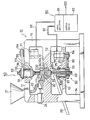
- the drawing is a schematic front view, partially in section, showing an electric powder compacting machine according to one embodiment of the present invention.
- the powder compacting machine is an electric one-axis punch press, which comprises a frame 10 including an upper wall 11, an intermediate wall 12, a lower wall 13, and side walls 14 and 15.
- a hopper 21 for the supply of powder material is mounted on one side of the upper wall 11, and the hopper 21 is connected, by means of a flexible hose 22, to a feeder 23 which is movably mounted on the intermediate wall 12.
- the feeder 23 is driven by an electromagnetic actuator 24 on the side wall 14 so that it reciprocates on the upper surface of the intermediate wall 12, between a shunting position and a powder material supply position right over a die space of a die-punch mechanism mentioned later. In the supply position, the powder material is fed into the die space through an opening in the bottom face of the feeder.
- a push member 25 and a chute 26 are arranged under the intermediate wall 12. Moldings formed in the die-punch mechanism are disengaged from the die-punch mechanism by means of the push member 25, which is driven by means of an electromagnetic actuator 27 provided on the lower surface of the intermediate wall 12, and are then taken out through the chute 26.
- the die-punch mechanism 30 for compressing the powder material comprises an integral die 31 and a pair of cylindrical punches 32 and 33.
- the die 31 which has a central through hole 31a extending along its axis, is fitted in stepped hole 12a, bored through the central portion of the intermediate wall 12 so as to extend in the direction of the height of the compacting machine, and is fixed to the intermediate wall 12 in a replaceable manner, by means of a ring-shaped fixing member 34.
- the upper and lower punches 32 and 33 are removably fitted in the hole 31a of the die 31 for sliding motion, and, in conjunction with the die 31, define the compacting die space 35 which is filled with the powder material.
- a drive mechanism 40 for driving the upper and lower punches 32 and 33 is provided with upper and lower drive sections 50 and 60 of substantially the same construction which correspond individually to the punches. Both the drive sections are disposed in alignment with the die-punch mechanism 30.
- the upper drive section 50 includes a ball nut 51, a ball screw 52 threadedly engaged therewith, and a timing gear 53 fixed to the ball nut 51 for rotation in unison therewith.
- the ball nut 51 is housed in a through hole lla, bored through the central portion of the upper wall 11 so as to extend in the direction of the height of the compacting machine, and is rotatably supported on the upper wall 11 by means of a bearing llb.
- the ball screw 52 is connected, at its inner end, to the upper punch 32 for movement in unison therewith.
- the upper drive section 50 includes a timing gear 54, which is fixed for integral rotation to the output shaft of an AC servomotor 71 fixed to the upper wall 11, and a timing belt 55 passed around and between the two gears 53 and 54.
- the lower drive section 60 includes a ball nut 61, a ball screw 62, timing gears 63 and 64, and a timing belt 65, which correspond to the elements 51 to 55, respectively.
- the inner end of the ball screw 62 is connected to the lower punch 33, and the gear 64 is fixed to the output shaft of an AC servomotor 72 which is fixed to the lower wall 13.
- the servo amplifier 81 which is connected to both the servomotors by means of power lines 91 and 92, is operable to control driving current to be applied to these motors.
- the control device 82 includes a keyboard for setting the compacting pressure and the like, an input section for receiving an output signal indicative of a detected compacting pressure from compacting pressure detecting means, e.g., a strain gage 100 attached to the ball nut 61 of the lower drive section 60, a comparator section for comparing the set compacting pressure and the detected compacting pressure, an output section for delivering a control output corresponding to the result of comparison to servo amplifier 81, and a memory section storing control programs and the like for various operations of the powder compacting machine.
- These control programs include various punch operation programs mentioned below, by way of example, for operating the upper and lower punches 32 and 33 in various modes.
- the die 31 corresponding to the type of the compact and the upper and lower punches 32 and 33 are mounted on the powder compacting machine, the required compacting pressure and punch operation program are selected by means of the keyboard of the control means 80, and the operation of the powder compacting machine is started.
- the compacting machine is operated under the control of the control means 80, in accordance with the control programs stored in the memory section of the control means 80.
- the upper punch 32 takes a shunting position in which it is upwardly disengaged from the central through hole 31a of the die 31, while the lower punch 33 is fitted in the hole 31a so that the die 31 and the lower punch 33 define a powder material receiving space (hereinafter referred to as die space 35) corresponding to the die space 35.
- the electromagnetic actuator 24 is operated to move the feeder 23 from the shunting position to the powder material supply position right over the die space 35, and the powder material supplied through the hopper 21 and hose 22 to the feeder 23 is filled into die space 35 through the opening in the bottom face of the feeder.
- the feeder 23 is returned to the shunting position. Then, the servomotor 71 is driven in the direction to produce the compacting pressure, thereby rotatively driving the ball nut 51 through the medium of the gear 54, the belt 55, and the gear 53, and the upper punch 32, which is integrally movable with the ball screw 52 threadedly engaged with the nut 51, is lowered to be fitted into the hole 31a of the die 31.
- the servomotor 72 is nonrotatably locked by means of, e.g., an electromagnetic brake (not shown) to keep the punch 33 in a fixed position, while the rotation of the servomotor 71 is continued so that the powder material is subjected to a push force by means of the upper punch 32.
- the compacting pressure is feedback-controlled as mentioned later. In consequence, variations in density and weight of compacts are extremely small.
- the servomotors 71 and 72 are driven simultaneously, so that a great compacting pressure can be obtained.
- a portion with relatively low green density can be formed in any desired region of the compact with respect to the direction of its height. More specifically, the low-density portion can be formed in the central portion of the compact, with respect to its height direction, by controlling the output torques of the two motors for substantially the same value.
- the low-density portion can be formed on either one side of the compact deviated from the central portion with respect to the height direction. Also in accordance with this operation program, the density and weight of the compacts can be made uniform.
- the upper and lower punches 32 and 33 are pressed alternately. Owing to vibration caused by this operation, compacts with high and uniform green density can be obtained, so that variations between compacts can be eliminated.
- the powder material for one compact is supplied by a plurality of installments to the die space 35, and the press operation by means of the upper punch 32 is performed each time the lot supply of the material is finished.
- the upper punch 32 is disengaged from the hole 31a of the die 31 and moved up to the shunting position, while being finely reciprocated, whereupon the powder material is additionally supplied.
- the green density distribution of the compacts is adjustable. More specifically, the green density distribution can be made uniform by controlling the push force for the press operation for each lot of the supplied material so as to be fixed.
- the green density can be changed with respect to the height direction of the compacts. Since the supply of the powder material and the press operation of the upper punch 32 are performed a plurality of times, as mentioned before, a tamping effect is produced, so that the green density distribution can be made uniform even for compacts of complicated shapes or elongated configuration.
- the output signal from the strain gage 100 is applied to the comparator section of the control device 82 of the control means 80 through the input section of the device, and is compared to the set compacting pressure in the comparator section.
- the output torque or torques of one or both of the servomotors 71 and 72 are controlled by means of the servo amplifier 81 of the control means 80 for receiving the control output corresponding to the comparison result.
- the following operation is performed by controlling a corresponding one or ones of the servomotors 71 and 72 and the electromagnetic actuator 27.
- the push force produced between the upper and lower punches 32 and 33 is reduced, and the compact held between the two punches is then disengaged from the hole 31a of the die 31 and moved to a predetermined height-direction position below the hole.
- the upper punch 32 is moved up to the shunting position above the die 31.
- the compact placed on the lower punch 33 is dropped onto the chute 26 by means of the push member 25, and is transferred to the outside through the chute.
- the lower punch 33 is fitted into the hole 31a of the die 31, whereupon the operation for one compact is finished.
- the present invention is applied to a one-axis punch press having a integral die and a pair of punches.
- the present invention is not limited to this, and may be also applied to various powder compacting machines of types capable of executing the aforementioned compacting pressure control, and the various elements of the powder compacting machines may be modified variously.
- a rack and pinion mechanism may be used in place of the ball-nut/ball-screw mechanism of the above embodiment, and a load cell may be used in place of the strain gage.
- the strain gage is attached to the ball nut of the lower drive section.
- it may be attached to a suitable part of the drive mechanism permitting the detection of the compacting pressure.
Landscapes
- Engineering & Computer Science (AREA)
- Mechanical Engineering (AREA)
- Press Drives And Press Lines (AREA)
- Powder Metallurgy (AREA)
- Control Of Presses (AREA)
- Processing And Handling Of Plastics And Other Materials For Molding In General (AREA)
- Casting Or Compression Moulding Of Plastics Or The Like (AREA)
Abstract
Description
- The present invention relates to a powder compacting machine, and more particularly, to an electric powder compacting machine in which a compacting pressure on a powder compacting material in a die-punch mechanism can be accurately controlled, and adjustment work after the replacement of the die-punch mechanism can be accomplished with ease.
- Conventionally, compacts, such as machine parts, are obtained with use of a powder compacting machine in which a punch slidably fitted in a die is driven by means of a hydraulic or electric drive mechanism, for compaction of a powder material in a compacting die space defined by the die and the punch. In general, the powder compacting machine of this type is not provided with a pressure control mechanism for controlling a compacting pressure to be applied to the powder material by means of the punch. Even if the punch is driven under constant conditions, therefore, the compacting pressure varies, accompanying changes of the compacting machine temperature and the ambient temperature and wear of components of the drive mechanism, such as a link mechanism. Thus, the individual compacts are liable to vary from one another in density and weight. In other words, as the compacting pressure varies, the dimensions of one compact vary from those of another even though the die space is filled with a certain powder material. Moreover, the compacts vary from one another in weight even if the powder material for one compact is supplied by a plurality of installments to obtain a compact of predetermined dimensions.
- In order to eliminate these awkward problems, as is generally known, the powder compacting machine is provided with a mechanism for adjusting the compacting pressure. The conventional pressure adjusting mechanism, however, is composed of a number of mechanical components, so that its construction is complicated. Moreover, it requires troublesome adjustment work before operation, especially after the replacement of the die and the punch, accompanying change of compacting conditions.
- The object of the present invention is to provide an electric powder compacting machine in which a compacting pressure can be accurately controlled, and adjustment work accompanying the replacement of a die- punch mechanism is easy.
- In order to achieve the above object, an electric powder compacting machine according to the present invention comprises a die-punch mechanism including a die and at least one punch, the at least one punch, in conjunction with the die, defining a die space and being movable relatively to the die for the compaction of a powder material in the die space. The at least one punch is operatively connected to at least one servomotor by means of a drive mechanism. The drive mechanism is driven by means of the at least one servomotor to move the at least one punch relatively to the die. A compacting pressure produced by this relative movement is detected by detecting means, and control means, which is connected to the detecting means and the at least one servomotor, is operable to control the drive of the at least one servomotor in accordance with an output signal from the detecting means, indicative of the actual compacting pressure, so that the compacting pressure attains a predetermined value.
- According to the present invention, as described above, feedback control is effected in accordance with the detected value of the actual compacting pressure, so that compacts with required green density distribution, e.g., uniform distribution, and high dimensional accuracy can be obtained. Moreover, electric compacting pressure control is effected by the control means through the medium of the servomotor, while the punch is being pressed. Even when the die- punch mechanism is replaced as compacting conditions, such as the compact type, are changed, therefore, there is no need of troublesome adjustment work which is required when a pressure control mechanism composed of many machine parts is used. Thus, the powder compacting machine is high in production efficiency and operability. Also, there is no possibility of soiling by oil, and noises and vibrations can be reduced, so that the working environment is fine. In contrast with the case of a conventional hydraulic powder compacting machine, furthermore, energy consumption can be reduced to about one-third, so that running costs can be lowered.
- The drawing is a schematic front view, partially in section, showing an electric powder compacting machine according to one embodiment of the present invention.
- An electric powder compacting machine according to one embodiment of the present invention will now be described with reference to the drawing.
- The powder compacting machine is an electric one-axis punch press, which comprises a
frame 10 including anupper wall 11, an intermediate wall 12, alower wall 13, andside walls hopper 21 for the supply of powder material is mounted on one side of theupper wall 11, and thehopper 21 is connected, by means of aflexible hose 22, to afeeder 23 which is movably mounted on the intermediate wall 12. Thefeeder 23 is driven by anelectromagnetic actuator 24 on theside wall 14 so that it reciprocates on the upper surface of the intermediate wall 12, between a shunting position and a powder material supply position right over a die space of a die-punch mechanism mentioned later. In the supply position, the powder material is fed into the die space through an opening in the bottom face of the feeder. Apush member 25 and achute 26 are arranged under the intermediate wall 12. Moldings formed in the die-punch mechanism are disengaged from the die-punch mechanism by means of thepush member 25, which is driven by means of anelectromagnetic actuator 27 provided on the lower surface of the intermediate wall 12, and are then taken out through thechute 26. - The die-
punch mechanism 30 for compressing the powder material comprises an integral die 31 and a pair ofcylindrical punches lower punches die space 35 which is filled with the powder material. - A drive mechanism 40 for driving the upper and
lower punches lower drive sections punch mechanism 30. Theupper drive section 50 includes aball nut 51, aball screw 52 threadedly engaged therewith, and atiming gear 53 fixed to theball nut 51 for rotation in unison therewith. Theball nut 51 is housed in a through hole lla, bored through the central portion of theupper wall 11 so as to extend in the direction of the height of the compacting machine, and is rotatably supported on theupper wall 11 by means of a bearing llb. Theball screw 52 is connected, at its inner end, to theupper punch 32 for movement in unison therewith. Further, theupper drive section 50 includes atiming gear 54, which is fixed for integral rotation to the output shaft of anAC servomotor 71 fixed to theupper wall 11, and atiming belt 55 passed around and between the twogears lower drive section 60 includes aball nut 61, aball screw 62,timing gears timing belt 65, which correspond to theelements 51 to 55, respectively. The inner end of theball screw 62 is connected to thelower punch 33, and thegear 64 is fixed to the output shaft of anAC servomotor 72 which is fixed to thelower wall 13. - Control means 80 for controlling the drive of various operating sections of the powder compacting machine, including the
servomotors servo amplifier 81 and acontrol device 82 for controlling the amplifier. Theservo amplifier 81, which is connected to both the servomotors by means ofpower lines control device 82, whose arrangement is not shown, includes a keyboard for setting the compacting pressure and the like, an input section for receiving an output signal indicative of a detected compacting pressure from compacting pressure detecting means, e.g., astrain gage 100 attached to theball nut 61 of thelower drive section 60, a comparator section for comparing the set compacting pressure and the detected compacting pressure, an output section for delivering a control output corresponding to the result of comparison toservo amplifier 81, and a memory section storing control programs and the like for various operations of the powder compacting machine. These control programs include various punch operation programs mentioned below, by way of example, for operating the upper andlower punches - (i) A first operation program for applying the compacting pressure by means of the
upper punch 32 with thelower punch 33 held in a predetermined position. - (ii) A second operation program for applying the compacting pressure by means of the upper and
lower punches - (iii) A third operation program for alternately operating the upper and
lower punches - (iv) A fourth operation program for supplying the powder material for one compact by a plurality of installments and applying the compacting pressure by means of only the
upper punch 32. - The following is a description of the operation of the powder compacting machine constructed as aforesaid.
- First, the die 31 corresponding to the type of the compact and the upper and
lower punches - The compacting machine is operated under the control of the control means 80, in accordance with the control programs stored in the memory section of the control means 80. At the start of the operation, the
upper punch 32 takes a shunting position in which it is upwardly disengaged from the central through hole 31a of the die 31, while thelower punch 33 is fitted in the hole 31a so that the die 31 and thelower punch 33 define a powder material receiving space (hereinafter referred to as die space 35) corresponding to thedie space 35. Then, theelectromagnetic actuator 24 is operated to move thefeeder 23 from the shunting position to the powder material supply position right over thedie space 35, and the powder material supplied through thehopper 21 andhose 22 to thefeeder 23 is filled intodie space 35 through the opening in the bottom face of the feeder. After the material filling, thefeeder 23 is returned to the shunting position. Then, theservomotor 71 is driven in the direction to produce the compacting pressure, thereby rotatively driving theball nut 51 through the medium of thegear 54, thebelt 55, and thegear 53, and theupper punch 32, which is integrally movable with theball screw 52 threadedly engaged with thenut 51, is lowered to be fitted into the hole 31a of the die 31. - If the first punch operation program is selected, the
servomotor 72 is nonrotatably locked by means of, e.g., an electromagnetic brake (not shown) to keep thepunch 33 in a fixed position, while the rotation of theservomotor 71 is continued so that the powder material is subjected to a push force by means of theupper punch 32. During the compacting operation in accordance with this program, the compacting pressure is feedback-controlled as mentioned later. In consequence, variations in density and weight of compacts are extremely small. - If the second operation program is selected, the
servomotors servomotors - If the third operation program is selected, the upper and
lower punches - If the fourth operation program is selected, the powder material for one compact is supplied by a plurality of installments to the die
space 35, and the press operation by means of theupper punch 32 is performed each time the lot supply of the material is finished. When the press operation for the lot- supplied material is completed, theupper punch 32 is disengaged from the hole 31a of the die 31 and moved up to the shunting position, while being finely reciprocated, whereupon the powder material is additionally supplied. According to such compacting operation, the green density distribution of the compacts is adjustable. More specifically, the green density distribution can be made uniform by controlling the push force for the press operation for each lot of the supplied material so as to be fixed. By varying the push force depending on the press operation, on the other hand, the green density can be changed with respect to the height direction of the compacts. Since the supply of the powder material and the press operation of theupper punch 32 are performed a plurality of times, as mentioned before, a tamping effect is produced, so that the green density distribution can be made uniform even for compacts of complicated shapes or elongated configuration. - While the compacting operation is being executed in accordance with the selected one of the various punch operation programs, including the aforementioned first to fourth programs, the output signal from the
strain gage 100, indicative of the actual compacting pressure, is applied to the comparator section of thecontrol device 82 of the control means 80 through the input section of the device, and is compared to the set compacting pressure in the comparator section. The output torque or torques of one or both of theservomotors servo amplifier 81 of the control means 80 for receiving the control output corresponding to the comparison result. When the detected compacting pressure attains a set value so that the manufacture of the compact is finished, the following operation is performed by controlling a corresponding one or ones of theservomotors electromagnetic actuator 27. First, the push force produced between the upper andlower punches upper punch 32 is moved up to the shunting position above the die 31. The compact placed on thelower punch 33 is dropped onto thechute 26 by means of thepush member 25, and is transferred to the outside through the chute. Finally, thelower punch 33 is fitted into the hole 31a of the die 31, whereupon the operation for one compact is finished. - According to the embodiment described above, the present invention is applied to a one-axis punch press having a integral die and a pair of punches. However, the present invention is not limited to this, and may be also applied to various powder compacting machines of types capable of executing the aforementioned compacting pressure control, and the various elements of the powder compacting machines may be modified variously. For example, a rack and pinion mechanism may be used in place of the ball-nut/ball-screw mechanism of the above embodiment, and a load cell may be used in place of the strain gage. In the above embodiment, moreover, the strain gage is attached to the ball nut of the lower drive section. Alternatively, however, it may be attached to a suitable part of the drive mechanism permitting the detection of the compacting pressure.
Claims (6)
Applications Claiming Priority (2)
| Application Number | Priority Date | Filing Date | Title |
|---|---|---|---|
| JP5704/88 | 1988-01-16 | ||
| JP63005704A JP2519498B2 (en) | 1988-01-16 | 1988-01-16 | Electric powder molding machine |
Publications (3)
| Publication Number | Publication Date |
|---|---|
| EP0358770A1 true EP0358770A1 (en) | 1990-03-21 |
| EP0358770A4 EP0358770A4 (en) | 1991-08-07 |
| EP0358770B1 EP0358770B1 (en) | 1993-10-27 |
Family
ID=11618502
Family Applications (1)
| Application Number | Title | Priority Date | Filing Date |
|---|---|---|---|
| EP89901315A Expired - Lifetime EP0358770B1 (en) | 1988-01-16 | 1989-01-13 | Electric powder molding machine |
Country Status (5)
| Country | Link |
|---|---|
| EP (1) | EP0358770B1 (en) |
| JP (1) | JP2519498B2 (en) |
| KR (1) | KR900700277A (en) |
| DE (1) | DE68910248T2 (en) |
| WO (1) | WO1989006597A1 (en) |
Cited By (11)
| Publication number | Priority date | Publication date | Assignee | Title |
|---|---|---|---|---|
| FR2661343A1 (en) * | 1990-04-27 | 1991-10-31 | Le Molaire Roger | Method and machine for manufacturing a sintered product with continuous adjustment of the parameters |
| EP0482360A3 (en) * | 1990-10-25 | 1992-08-19 | Robert Bosch Gmbh | Motor-driven press with load and displacement sensors |
| US5297897A (en) * | 1989-11-24 | 1994-03-29 | Asm Fico Tooling B.V. | Single-strip molding apparatus |
| EP0633111A3 (en) * | 1989-11-24 | 1996-06-05 | Fico Bv | Single strip molding apparatus with movable half-molds. |
| WO2004014639A3 (en) * | 2002-08-12 | 2004-04-01 | Tiy Inc | An apparatus for bench scale tablet-making |
| EP1129802A3 (en) * | 2000-03-04 | 2004-05-06 | Fette GmbH | Process for controlling the pressing force for metal powder compression |
| EP2311587A1 (en) * | 2009-10-13 | 2011-04-20 | Osterwalder AG | Powder press |
| WO2011051626A1 (en) * | 2009-10-30 | 2011-05-05 | Medelpharm | Facility for producing a solid product using one or more powder materials |
| CN105584088A (en) * | 2016-03-19 | 2016-05-18 | 伍宜松 | Precise powder forming machine |
| CN110788320A (en) * | 2019-08-23 | 2020-02-14 | 广州力鸿自动化设备有限公司 | Automatic change servo powder forming machine of precision |
| CN110947958A (en) * | 2019-12-10 | 2020-04-03 | 西安欧中材料科技有限公司 | Metal powder spinning forming device and forming method thereof |
Families Citing this family (8)
| Publication number | Priority date | Publication date | Assignee | Title |
|---|---|---|---|---|
| DE10218633B3 (en) * | 2002-04-25 | 2004-08-19 | Tmd Friction Europe Gmbh | Press |
| WO2008114827A1 (en) | 2007-03-20 | 2008-09-25 | Tungaloy Corporation | Compression molding method of throw-away tip |
| DE102009049845A1 (en) * | 2009-10-19 | 2011-04-21 | Dorst Technologies Gmbh & Co. Kg | Metal- or ceramic powder-electropress comprises a press drive that is arranged for driving a stamp arrangement for pressing a powder and/or granulates in a matrix to a press part, a control device for controlling the press drive |
| DE102010033997A1 (en) * | 2010-08-11 | 2012-02-16 | Dorst Technologies Gmbh & Co. Kg | Metal- or ceramic powder-electric press comprises stamp arrangement, spindle drive motor, spindle assembly, position determining device, control device, and transfer arrangement, which is adjustably arranged to displacement amount |
| CN101979245B (en) * | 2010-10-14 | 2014-06-04 | 西安交通大学 | Single punch tablet press |
| JP2013220446A (en) * | 2012-04-17 | 2013-10-28 | Mitsubishi Materials Techno Corp | Method of manufacturing powder molding and powder molding apparatus |
| CN105690850A (en) * | 2016-04-27 | 2016-06-22 | 广州市精程达精密机械有限公司 | High-precision powder forming machine |
| CN107824692B (en) * | 2017-12-07 | 2019-02-15 | 安徽吉思特智能装备有限公司 | A kind of stamping die of harvester pick-up machine pawl |
Family Cites Families (8)
| Publication number | Priority date | Publication date | Assignee | Title |
|---|---|---|---|---|
| US2885618A (en) * | 1957-02-07 | 1959-05-05 | Stokes F J Corp | Motor control system |
| US3353215A (en) | 1965-11-10 | 1967-11-21 | Haller John | Powdered material briquetting press |
| GB1216397A (en) * | 1968-04-02 | 1970-12-23 | Keith Marshall | Improvements in or relating to tablet forming machines |
| JPS61242794A (en) * | 1985-04-22 | 1986-10-29 | Mitsubishi Electric Corp | Control device for pressurizing press |
| JPS6267695U (en) * | 1985-10-15 | 1987-04-27 | ||
| JPS62202002A (en) * | 1986-03-03 | 1987-09-05 | Hitachi Metals Ltd | Nc mechanical press |
| JPS63120000A (en) * | 1986-11-05 | 1988-05-24 | Hitachi Metals Ltd | Nc mechanical press for powder molding |
| JPS63256296A (en) * | 1987-04-13 | 1988-10-24 | Hitachi Metals Ltd | Nc mechanical press for powder molding |
-
1988
- 1988-01-16 JP JP63005704A patent/JP2519498B2/en not_active Expired - Fee Related
-
1989
- 1989-01-13 EP EP89901315A patent/EP0358770B1/en not_active Expired - Lifetime
- 1989-01-13 WO PCT/JP1989/000032 patent/WO1989006597A1/en not_active Ceased
- 1989-01-13 KR KR1019890701691A patent/KR900700277A/en not_active Withdrawn
- 1989-01-13 DE DE89901315T patent/DE68910248T2/en not_active Expired - Fee Related
Cited By (17)
| Publication number | Priority date | Publication date | Assignee | Title |
|---|---|---|---|---|
| US5297897A (en) * | 1989-11-24 | 1994-03-29 | Asm Fico Tooling B.V. | Single-strip molding apparatus |
| EP0633111A3 (en) * | 1989-11-24 | 1996-06-05 | Fico Bv | Single strip molding apparatus with movable half-molds. |
| EP0655323A3 (en) * | 1989-11-24 | 1996-06-05 | Fico Bv | Single band molding apparatus with means for applying pressure. |
| FR2661343A1 (en) * | 1990-04-27 | 1991-10-31 | Le Molaire Roger | Method and machine for manufacturing a sintered product with continuous adjustment of the parameters |
| EP0482360A3 (en) * | 1990-10-25 | 1992-08-19 | Robert Bosch Gmbh | Motor-driven press with load and displacement sensors |
| EP1129802A3 (en) * | 2000-03-04 | 2004-05-06 | Fette GmbH | Process for controlling the pressing force for metal powder compression |
| EP1129802B2 (en) † | 2000-03-04 | 2010-08-11 | Fette GmbH | Process for controlling the pressing force for metal powder compression |
| WO2004014639A3 (en) * | 2002-08-12 | 2004-04-01 | Tiy Inc | An apparatus for bench scale tablet-making |
| EP2311587A1 (en) * | 2009-10-13 | 2011-04-20 | Osterwalder AG | Powder press |
| WO2011045303A3 (en) * | 2009-10-13 | 2011-07-14 | Osterwalder Ag | Powder press |
| WO2011051626A1 (en) * | 2009-10-30 | 2011-05-05 | Medelpharm | Facility for producing a solid product using one or more powder materials |
| FR2951989A1 (en) * | 2009-10-30 | 2011-05-06 | Medelpharm | INSTALLATION FOR PRODUCING A SOLID PRODUCT FROM ONE OR MORE PULVERULENT MATERIALS |
| US8668483B2 (en) | 2009-10-30 | 2014-03-11 | Medelpharm | Facility for producing a solid product using one or more powder materials |
| CN105584088A (en) * | 2016-03-19 | 2016-05-18 | 伍宜松 | Precise powder forming machine |
| CN110788320A (en) * | 2019-08-23 | 2020-02-14 | 广州力鸿自动化设备有限公司 | Automatic change servo powder forming machine of precision |
| CN110788320B (en) * | 2019-08-23 | 2021-11-16 | 广州力鸿自动化设备有限公司 | Automatic change servo powder forming machine of precision |
| CN110947958A (en) * | 2019-12-10 | 2020-04-03 | 西安欧中材料科技有限公司 | Metal powder spinning forming device and forming method thereof |
Also Published As
| Publication number | Publication date |
|---|---|
| JPH01181997A (en) | 1989-07-19 |
| DE68910248D1 (en) | 1993-12-02 |
| EP0358770A4 (en) | 1991-08-07 |
| DE68910248T2 (en) | 1994-03-03 |
| KR900700277A (en) | 1990-08-13 |
| EP0358770B1 (en) | 1993-10-27 |
| JP2519498B2 (en) | 1996-07-31 |
| WO1989006597A1 (en) | 1989-07-27 |
Similar Documents
| Publication | Publication Date | Title |
|---|---|---|
| EP0358770B1 (en) | Electric powder molding machine | |
| JP4331793B2 (en) | Equipment for producing molded bodies | |
| EP2123435B1 (en) | Compression molding method for a cutting insert | |
| US5288440A (en) | Method and apparatus for controlling powder molding press | |
| US6074584A (en) | Method and device for manufacturing pressed parts from hard metal, ceramic, sintered metal or likewise | |
| DE69936821T2 (en) | Method for lowering the pressure in the plasticizing and dosing process for a motor-driven injection molding machine | |
| CN105102208B (en) | For controlling the method and the extruder of ceramics or metal dust extruder | |
| US20170312810A1 (en) | Hydraulic forging press and method for controlling same | |
| CN101248398A (en) | Method and device for controlling and regulating slide movement on a servo-electric press | |
| JP2013220446A (en) | Method of manufacturing powder molding and powder molding apparatus | |
| KR20100101100A (en) | Drive apparatus and method for a press machine | |
| EP1136226B1 (en) | Method and apparatus for controlling injection molding machine capable of reducing variations in weight of molded products | |
| US20060127268A1 (en) | Powder compacting method and powder compacting device | |
| KR100781914B1 (en) | Press forming machine | |
| JPH0557497A (en) | Nc powder compacting machine | |
| JP2657911B2 (en) | Electric powder molding machine | |
| JPH0557498A (en) | Motor driven powder compacting machine | |
| JPH07266086A (en) | Ram driving device for metal plate working machine | |
| JP2018161657A (en) | Motion generation apparatus, press apparatus, motion generation method, and motion generation program | |
| EP0541963B1 (en) | Method and apparatus for producing concrete products with a controlled degree of compaction | |
| JPS63120000A (en) | Nc mechanical press for powder molding | |
| CA2196560C (en) | Device for producing pressed articles | |
| US7147820B2 (en) | Method and apparatus for minimizing the spread of maximum compression forces in a powder press | |
| JP2662910B2 (en) | Vibration compression molding machine | |
| JPS5838696A (en) | Device for adjusting very small quantity of powder charged in powder molding press |
Legal Events
| Date | Code | Title | Description |
|---|---|---|---|
| PUAI | Public reference made under article 153(3) epc to a published international application that has entered the european phase |
Free format text: ORIGINAL CODE: 0009012 |
|
| 17P | Request for examination filed |
Effective date: 19890710 |
|
| AK | Designated contracting states |
Kind code of ref document: A1 Designated state(s): DE FR GB |
|
| RIN1 | Information on inventor provided before grant (corrected) |
Inventor name: MURANAKA, MASAKI Inventor name: WATANABE, KIKUO, ROOM 7-209, FANUC MANSHONHARIMOM Inventor name: NAITO, HIDEO Inventor name: INABA, YOSHIHARU |
|
| A4 | Supplementary search report drawn up and despatched |
Effective date: 19910619 |
|
| AK | Designated contracting states |
Kind code of ref document: A4 Designated state(s): DE FR GB |
|
| 17Q | First examination report despatched |
Effective date: 19920904 |
|
| GRAA | (expected) grant |
Free format text: ORIGINAL CODE: 0009210 |
|
| AK | Designated contracting states |
Kind code of ref document: B1 Designated state(s): DE FR GB |
|
| PG25 | Lapsed in a contracting state [announced via postgrant information from national office to epo] |
Ref country code: FR Effective date: 19931027 |
|
| REF | Corresponds to: |
Ref document number: 68910248 Country of ref document: DE Date of ref document: 19931202 |
|
| EN | Fr: translation not filed | ||
| PLBE | No opposition filed within time limit |
Free format text: ORIGINAL CODE: 0009261 |
|
| STAA | Information on the status of an ep patent application or granted ep patent |
Free format text: STATUS: NO OPPOSITION FILED WITHIN TIME LIMIT |
|
| 26N | No opposition filed | ||
| PGFP | Annual fee paid to national office [announced via postgrant information from national office to epo] |
Ref country code: GB Payment date: 19980105 Year of fee payment: 10 |
|
| PG25 | Lapsed in a contracting state [announced via postgrant information from national office to epo] |
Ref country code: GB Free format text: LAPSE BECAUSE OF NON-PAYMENT OF DUE FEES Effective date: 19990113 |
|
| GBPC | Gb: european patent ceased through non-payment of renewal fee |
Effective date: 19990113 |
|
| PGFP | Annual fee paid to national office [announced via postgrant information from national office to epo] |
Ref country code: DE Payment date: 19991231 Year of fee payment: 12 |
|
| PG25 | Lapsed in a contracting state [announced via postgrant information from national office to epo] |
Ref country code: DE Free format text: LAPSE BECAUSE OF NON-PAYMENT OF DUE FEES Effective date: 20011101 |