EP0358349B1 - Central tire inflation system - Google Patents
Central tire inflation system Download PDFInfo
- Publication number
- EP0358349B1 EP0358349B1 EP89308275A EP89308275A EP0358349B1 EP 0358349 B1 EP0358349 B1 EP 0358349B1 EP 89308275 A EP89308275 A EP 89308275A EP 89308275 A EP89308275 A EP 89308275A EP 0358349 B1 EP0358349 B1 EP 0358349B1
- Authority
- EP
- European Patent Office
- Prior art keywords
- valve
- conduit
- tire
- deflate
- shut
- Prior art date
- Legal status (The legal status is an assumption and is not a legal conclusion. Google has not performed a legal analysis and makes no representation as to the accuracy of the status listed.)
- Expired - Lifetime
Links
Images


Classifications
-
- B—PERFORMING OPERATIONS; TRANSPORTING
- B60—VEHICLES IN GENERAL
- B60C—VEHICLE TYRES; TYRE INFLATION; TYRE CHANGING; CONNECTING VALVES TO INFLATABLE ELASTIC BODIES IN GENERAL; DEVICES OR ARRANGEMENTS RELATED TO TYRES
- B60C23/00—Devices for measuring, signalling, controlling, or distributing tyre pressure or temperature, specially adapted for mounting on vehicles; Arrangement of tyre inflating devices on vehicles, e.g. of pumps or of tanks; Tyre cooling arrangements
- B60C23/10—Arrangement of tyre-inflating pumps mounted on vehicles
-
- B—PERFORMING OPERATIONS; TRANSPORTING
- B60—VEHICLES IN GENERAL
- B60C—VEHICLE TYRES; TYRE INFLATION; TYRE CHANGING; CONNECTING VALVES TO INFLATABLE ELASTIC BODIES IN GENERAL; DEVICES OR ARRANGEMENTS RELATED TO TYRES
- B60C23/00—Devices for measuring, signalling, controlling, or distributing tyre pressure or temperature, specially adapted for mounting on vehicles; Arrangement of tyre inflating devices on vehicles, e.g. of pumps or of tanks; Tyre cooling arrangements
- B60C23/001—Devices for manually or automatically controlling or distributing tyre pressure whilst the vehicle is moving
- B60C23/003—Devices for manually or automatically controlling or distributing tyre pressure whilst the vehicle is moving comprising rotational joints between vehicle-mounted pressure sources and the tyres
- B60C23/00372—Devices for manually or automatically controlling or distributing tyre pressure whilst the vehicle is moving comprising rotational joints between vehicle-mounted pressure sources and the tyres characterised by fluid diagrams
-
- B—PERFORMING OPERATIONS; TRANSPORTING
- B60—VEHICLES IN GENERAL
- B60C—VEHICLE TYRES; TYRE INFLATION; TYRE CHANGING; CONNECTING VALVES TO INFLATABLE ELASTIC BODIES IN GENERAL; DEVICES OR ARRANGEMENTS RELATED TO TYRES
- B60C23/00—Devices for measuring, signalling, controlling, or distributing tyre pressure or temperature, specially adapted for mounting on vehicles; Arrangement of tyre inflating devices on vehicles, e.g. of pumps or of tanks; Tyre cooling arrangements
- B60C23/001—Devices for manually or automatically controlling or distributing tyre pressure whilst the vehicle is moving
- B60C23/003—Devices for manually or automatically controlling or distributing tyre pressure whilst the vehicle is moving comprising rotational joints between vehicle-mounted pressure sources and the tyres
- B60C23/00354—Details of valves
-
- Y—GENERAL TAGGING OF NEW TECHNOLOGICAL DEVELOPMENTS; GENERAL TAGGING OF CROSS-SECTIONAL TECHNOLOGIES SPANNING OVER SEVERAL SECTIONS OF THE IPC; TECHNICAL SUBJECTS COVERED BY FORMER USPC CROSS-REFERENCE ART COLLECTIONS [XRACs] AND DIGESTS
- Y10—TECHNICAL SUBJECTS COVERED BY FORMER USPC
- Y10T—TECHNICAL SUBJECTS COVERED BY FORMER US CLASSIFICATION
- Y10T137/00—Fluid handling
- Y10T137/8593—Systems
- Y10T137/86493—Multi-way valve unit
- Y10T137/86574—Supply and exhaust
Definitions
- This invention relates to a vehicular central tire inflation system (CTIS), also know as tire pressure regulating systems, wherein the inflation pressure of vehicle tires may be controlled from a remote location (usually the vehicle cab with the vehicle at rest and/or in motion and utilizing an on board source of pressurized air).
- CIS vehicular central tire inflation system
- remote location usually the vehicle cab with the vehicle at rest and/or in motion and utilizing an on board source of pressurized air.
- CTIS for a vehicle as may be seen by reference to U.S. Patent No. 4,640,331, hereby incorporated by reference, which utilizes a control valve and a low tire pressure shut off valve at each wheel end assembly which are connected to a central control system by a single pressure line or conduit through a rotary seal assembly. Pressurization of the single pressure conduit is effective to open and close communication to the vehicle tire and to cause inflation and/or deflation of the tire to a selected pressure. While the above CTIS has been satisfactorily employed, it is controlled during deflation by a pressure regulator which inaccurately controls deflating pressure.
- an object of the present invention to provide an improved central tire inflation system with a relief valve in the air circuit which provides the necessary pressure drop for deflation and also to provide make up air to accomodate minor line and fitting leaks by feeding make up air into the air circuit either during deflation of the tire or immediately thereafter via one of two solenoid valves in the air circuit.
- a vehicle on board tire inflation and tire deflation air circuit having control means for selectively pressurising and exhausting a first conduit in an air circuit to inflate a vehicle tire to a preselected higher pressure and to deflate the vehicle tire to a preselected lower pressure
- control means for selectively pressurising and exhausting a first conduit in an air circuit to inflate a vehicle tire to a preselected higher pressure and to deflate the vehicle tire to a preselected lower pressure
- a first normally closed solenoid pilot valve for actuating a deflate valve having an inlet port fluidly connected to said first conduit
- a second normally closed solenoid pilot valve for actuating a shut off valve having an inlet port connected to said first conduit, and an outlet port connected to atmosphere, said shut off valve being effective to establish fluid communication between said first conduit and atmosphere
- the control means further comprises a relief valve having an outlet port connected to atmosphere, said deflate valve having an outlet port fluidly connected to an inlet port in said relief valve, and being
- Fig. 1 is a schematic illustration of the pneumatic components of the prior art during the tire deflation mode of operation.
- Fig. 2 is a schematic illustration of the pneumatic components of the present invention during the tire deflation mode of operation.
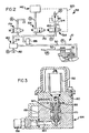
- Fig. 3 is a cross-sectional view of the tire deflate valve schematically illustrated in Fig. 2.
- Fig. 4 is an enlarged partial cross-sectional view of the tire deflate valve shown in Fig. 3.
- Fig. 5 is a cross-sectional view of the shut off valve schematically illustrated in Fig. 2.
- Fig. 1 and Fig. 2 of the drawings the pressurization of the various conduits and/or chambers is indicated by an “S" for supply pressure, receiving air from a supply 142 at pressure greater than or equal to the maximum tire pressure for the vehicle tires "R” for regulated pressure (8 to 10 psi), "A” for atmospheric pressure and “T” for tire pressure.
- Fig. 1 is a schematic illustration of the pneumatic components of the central tire inflation system disclosed in U.S. Patent 4,640,331 during a tire deflate mode of operation. Prior to the deflate mode of operation, conduits 50 and 170 are at substantially the same pressure as in the chamber 74 of the tire 12. Also, the solenoid inflate valve 154, the solenoid deflate valve 164, and the solenoid shut-off valve 174 are closed.
- solenoid deflate valve 164 Upon actuation of solenoid deflate valve 164, regulated pressure, such as 10psi, from the pressure regulator 156, will be present in conduits 160 and 170 and at port 178 of the quick release valve 180, causing the conduits 50, 52, 62 and 68, and tire chamber 74 to quickly bleed down toward the regulated pressure through exhaust port 182 of quick release valve 180. After a period of time, the deflate valve 164 will be closed and the inflate valve 154 will be momentarily actuated thereby, communicating the source of air S with conduit 170.
- regulated pressure such as 10psi
- the pressure regulator 156 is deleted from the circuit and a relief valve 158 substituted therefor as shown in Fig. 2 of the drawings.
- the pressurized air in line 170 passes through the deflate valve 164 towards the relief valve 158 which functions to release air to atmosphere so long as the pressure in lines or conduit 170, and 50, is above the low pressure setting of the relief valve 158.
- the deflate circuit is provided with an orifice which feeds make-up pressurized air into line or conduit 170 to compensate for leaks in the air circuit due to minor fitting leaks and the like.
- the deflate valve 164 includes a valve body 188, a top-plate 190 and an actuating solenoid operator 192 mounted thereon.
- a blind hole is formed in the body 188 in which is positioned a valve cartridge 194 having an outer tubular or cylindrical member 196 and a poppet element 198.
- the inner bore of the cylindrical member 196 is provided with spaced annular beveled valve seats 200 and 202 against which the conical seats 204 and 206 of the poppet element 198 are seated respectively.
- valve member 207 is moved away from the seat 220 against the bias of spring 211 so that pressurized air from conduit 222 flows through the hole in seat 220, into the space 218, and hence through the conduit 216 thereby, pressurizing the space 217 above the poppet element 198 and moving the element 198 and downwardly into the position shown in Fig. 4.
- Deflate valve 164 is a solenoid controlled, pilot air actuated valve. Such valves are well known in the prior art, as may be seen by reference to U.S. Patent 3,175,581.
- the pressurized air in conduit 222 may be provided in any convenient manner, such as via a conduit schematically shown by a dashed line 223 which communicates air from the source S in Figure 2 to conduit 222.
- the shut off valve is shown in the steady state or system shut off mode, at which time the shut off valve 174 is spring biased to open position so that conduit 170 is connected to atmosphere. Pressurized air in conduit 170 bypasses the seats 200 and 204 and is vented through the conduit 228 via an unshown opening.
- the shut off valve 174 is similar in construction and operation to the deflate valve 164, except that the poppet element 198 does not have an orifice 214 and hole 210. Instead the conduit 216 has a branch conduit 224 which is connected to conduit 226 by a very small orifice 214. The conduit 226 is connected to a second branch conduit 227 leading to the conduit 170.
- valve member 207 is moved away from the seat 220 and air flows into the chamber 218 and conduit 216 forcing the poppet element 198 downwardly.
- the seat 206 is opened and the seat 204 is closed and pressurized air from branch conduit 227 is bled into the conduit 170 to make up for small amounts of air lost through leaking fittings and the like.
- Pilot air is provided to conduit 222 in shut off valve 174 in the same manner described for deflate valve 164.
- Relief valve 158 which is shown in the background in Fig. 5, continues to be connected to deflate valve 164 via conduit 160.
Abstract
Description
- This invention relates to a vehicular central tire inflation system (CTIS), also know as tire pressure regulating systems, wherein the inflation pressure of vehicle tires may be controlled from a remote location (usually the vehicle cab with the vehicle at rest and/or in motion and utilizing an on board source of pressurized air).
- More particularly this invention relates to CTIS for a vehicle as may be seen by reference to U.S. Patent No. 4,640,331, hereby incorporated by reference, which utilizes a control valve and a low tire pressure shut off valve at each wheel end assembly which are connected to a central control system by a single pressure line or conduit through a rotary seal assembly. Pressurization of the single pressure conduit is effective to open and close communication to the vehicle tire and to cause inflation and/or deflation of the tire to a selected pressure. While the above CTIS has been satisfactorily employed, it is controlled during deflation by a pressure regulator which inaccurately controls deflating pressure.
- Accordingly it is an object of the present invention to provide an improved central tire inflation system with a relief valve in the air circuit which provides the necessary pressure drop for deflation and also to provide make up air to accomodate minor line and fitting leaks by feeding make up air into the air circuit either during deflation of the tire or immediately thereafter via one of two solenoid valves in the air circuit.
- In accordance with the present invention there is provided a vehicle on board tire inflation and tire deflation air circuit having control means for selectively pressurising and exhausting a first conduit in an air circuit to inflate a vehicle tire to a preselected higher pressure and to deflate the vehicle tire to a preselected lower pressure comprising;
a first normally closed solenoid pilot valve for actuating a deflate valve having an inlet port fluidly connected to said first conduit; and
a second normally closed solenoid pilot valve for actuating a shut off valve having an inlet port connected to said first conduit, and an outlet port connected to atmosphere, said shut off valve being effective to establish fluid communication between said first conduit and atmosphere,
characterised in that the control means further comprises a relief valve having an outlet port connected to atmosphere, said deflate valve having an outlet port fluidly connected to an inlet port in said relief valve, and being effective to establish fluid communication between said first conduit and the inlet port of said relief valve and said relief valve being effective to connect the outlet port thereof to atmosphere when the pressure in said first conduit is greater than a predetermined set pressure of said relief valve and to close said outlet port when the said set pressure is attained, and in that said first or said second solenoid pilot valve is effective to bleed pressurized air from said source to said first conduit via a small orifice and passageway means in said deflate valve or said shut off valve respectively. - The objects and advantages of the present invention will become apparent from a reading of the following description of the preferred embodiments taken in connection with the attached drawings.
- Fig. 1 is a schematic illustration of the pneumatic components of the prior art during the tire deflation mode of operation.
- Fig. 2 is a schematic illustration of the pneumatic components of the present invention during the tire deflation mode of operation.
- Fig. 3 is a cross-sectional view of the tire deflate valve schematically illustrated in Fig. 2.
- Fig. 4 is an enlarged partial cross-sectional view of the tire deflate valve shown in Fig. 3.
- Fig. 5 is a cross-sectional view of the shut off valve schematically illustrated in Fig. 2.
- In Fig. 1 and Fig. 2 of the drawings the pressurization of the various conduits and/or chambers is indicated by an "S" for supply pressure, receiving air from a supply 142 at pressure greater than or equal to the maximum tire pressure for the vehicle tires "R" for regulated pressure (8 to 10 psi), "A" for atmospheric pressure and "T" for tire pressure.
- Fig. 1 is a schematic illustration of the pneumatic components of the central tire inflation system disclosed in U.S. Patent 4,640,331 during a tire deflate mode of operation. Prior to the deflate mode of operation,
conduits chamber 74 of thetire 12. Also, thesolenoid inflate valve 154, thesolenoid deflate valve 164, and the solenoid shut-offvalve 174 are closed. Upon actuation ofsolenoid deflate valve 164, regulated pressure, such as 10psi, from thepressure regulator 156, will be present inconduits port 178 of thequick release valve 180, causing theconduits tire chamber 74 to quickly bleed down toward the regulated pressure throughexhaust port 182 ofquick release valve 180. After a period of time, thedeflate valve 164 will be closed and theinflate valve 154 will be momentarily actuated thereby, communicating the source of air S withconduit 170. This action causesquick release valve 180 to again balance the pressures inconduits pressure transducer 186 to determine if further deflation and/or inflation is required. At the end of the deflation operation, shut offvalve 174 will open,closing wheel valve 58. It is important to note that the pressure inconduit 170 and thus inport 178 on thequick release valve 180 will cause thequick release valve 180 to close and prevent further venting of the tire below the predetermined regulated pressure. - It has been determined that the system as described above will on occasion malfunction due to the nature of
regulator 156 as a device which regulates at a different pressure if flow thru it is reversed. In accordance with this invention, thepressure regulator 156 is deleted from the circuit and arelief valve 158 substituted therefor as shown in Fig. 2 of the drawings. Thus, during deflation the pressurized air inline 170 passes through thedeflate valve 164 towards therelief valve 158 which functions to release air to atmosphere so long as the pressure in lines orconduit relief valve 158. Additionally, the deflate circuit is provided with an orifice which feeds make-up pressurized air into line orconduit 170 to compensate for leaks in the air circuit due to minor fitting leaks and the like. - In Figs. 3, and 4 the
deflate valve 164 includes avalve body 188, a top-plate 190 and an actuatingsolenoid operator 192 mounted thereon. A blind hole is formed in thebody 188 in which is positioned avalve cartridge 194 having an outer tubular orcylindrical member 196 and apoppet element 198. The inner bore of thecylindrical member 196 is provided with spaced annular beveledvalve seats conical seats poppet element 198 are seated respectively. When thesolenoid operator 192 is de-energized, theconical seat 206 is sealed against thevalve seat 202 by thespring 208 so that pressurized air is prevented from flowing into theconduit 160 forconduit 170, which extends into the area betweenvalve seat solenoid operator 192 is energized,valve member 207 is moved away from the seat 220 against the bias ofspring 211 so that pressurized air fromconduit 222 flows through the hole in seat 220, into thespace 218, and hence through theconduit 216 thereby, pressurizing thespace 217 above thepoppet element 198 and moving theelement 198 and downwardly into the position shown in Fig. 4. Thus, theconical seat 206 is opened and theconical seat 204 is sealed against thevalve seat 200 and pressurized air may move from theconduit 170 through theconduit 160 and hence into therelief valve 158.Deflate valve 164 is a solenoid controlled, pilot air actuated valve. Such valves are well known in the prior art, as may be seen by reference to U.S. Patent 3,175,581. The pressurized air inconduit 222 may be provided in any convenient manner, such as via a conduit schematically shown by adashed line 223 which communicates air from the source S in Figure 2 to conduit 222. - Furthermore, when the
poppet element 198 is in the position shown in Fig. 4., pressurized air fromspace 217 will flow through a verysmall orifice 214 preferably approximately .01 inches in diameter andhole 210 inpoppet element 198, providing a small amount of air flow to thecontrol conduits solenoid 192 of thedeflate valve 164 is energized, pressurized air fromconduit 170 is exhausted to atmosphere via thecartridge valve 194, theconduit 160 and therelief valve 158. At the same time, make up air is bled from thespace 217 to theconduit 170 via the verysmall orifice 214 to bypass thedeflate valve 164 and make up for any air leakage losses in the CTIS air circuit. - It is of course within the scope of this invention to provide make up air via the solenoid shut off
valve 174 so that make up air is bled into the CTIS air circuit at a time other than the deflation mode when thedeflate valve 164 is energized and both the shut offvalve 174 and theinflate valve 154 are closed as shown in Fig. 2. - In Fig. 5, the shut off valve is shown in the steady state or system shut off mode, at which time the shut off
valve 174 is spring biased to open position so thatconduit 170 is connected to atmosphere. Pressurized air inconduit 170 bypasses theseats conduit 228 via an unshown opening. The shut offvalve 174 is similar in construction and operation to thedeflate valve 164, except that thepoppet element 198 does not have anorifice 214 andhole 210. Instead theconduit 216 has abranch conduit 224 which is connected toconduit 226 by a verysmall orifice 214. Theconduit 226 is connected to asecond branch conduit 227 leading to theconduit 170. - Assuming that the
solenoid operator 192 ofvalve 174 is energized, thevalve member 207 is moved away from the seat 220 and air flows into thechamber 218 andconduit 216 forcing thepoppet element 198 downwardly. Thus, theseat 206 is opened and theseat 204 is closed and pressurized air frombranch conduit 227 is bled into theconduit 170 to make up for small amounts of air lost through leaking fittings and the like. Pilot air is provided to conduit 222 in shut offvalve 174 in the same manner described fordeflate valve 164.Relief valve 158, which is shown in the background in Fig. 5, continues to be connected to deflatevalve 164 viaconduit 160.
Claims (5)
a first normally closed solenoid pilot valve (192) for actuating a deflate valve (164) having an inlet port fluidly connected to said first conduit (170); and
a second normally closed solenoid pilot valve (192) for actuating a shut off valve (174) having an inlet port connected to said first conduit (170), and an outlet port connected to atmosphere (A), said shut off valve (174) being effective to establish fluid communication between said first conduit (170) and atmosphere (A),
characterised in that the control means further comprises a relief valve (158) having an outlet port connected to atmosphere (A), said deflate valve (164) having an outlet port fluidly connected to an inlet port in said relief valve (158), and being effective to establish fluid communication between said first conduit (170) and the inlet port of said relief valve (158) and said relief valve (158) being effective to connect the outlet port thereof to atmosphere (A) when the pressure in said first conduit (170) is greater than a predetermined set pressure of said relief valve (158) and to close said outlet port when the said set pressure is attained, and in that said first or said second solenoid pilot valve (192) is effective to bleed pressurized air from said source (S) to said first conduit (170) via a small orifice (214) and passageway means (210,227) in said deflate valve (164) or said shut off valve (174) respectively.
Priority Applications (1)
| Application Number | Priority Date | Filing Date | Title |
|---|---|---|---|
| AT89308275T ATE76003T1 (en) | 1988-08-15 | 1989-08-15 | CENTRAL TIRE INFLATION DEVICE. |
Applications Claiming Priority (2)
| Application Number | Priority Date | Filing Date | Title |
|---|---|---|---|
| US07/232,262 US4924926A (en) | 1988-08-15 | 1988-08-15 | Central tire inflation system |
| US232262 | 1988-08-15 |
Publications (2)
| Publication Number | Publication Date |
|---|---|
| EP0358349A1 EP0358349A1 (en) | 1990-03-14 |
| EP0358349B1 true EP0358349B1 (en) | 1992-05-13 |
Family
ID=22872448
Family Applications (1)
| Application Number | Title | Priority Date | Filing Date |
|---|---|---|---|
| EP89308275A Expired - Lifetime EP0358349B1 (en) | 1988-08-15 | 1989-08-15 | Central tire inflation system |
Country Status (11)
| Country | Link |
|---|---|
| US (1) | US4924926A (en) |
| EP (1) | EP0358349B1 (en) |
| JP (1) | JP2676164B2 (en) |
| KR (1) | KR950010357B1 (en) |
| AT (1) | ATE76003T1 (en) |
| BR (1) | BR8904181A (en) |
| CA (1) | CA1309331C (en) |
| DE (1) | DE68901515D1 (en) |
| ES (1) | ES2031689T3 (en) |
| IL (1) | IL91170A (en) |
| ZA (1) | ZA896184B (en) |
Families Citing this family (65)
| Publication number | Priority date | Publication date | Assignee | Title |
|---|---|---|---|---|
| IL95276A (en) * | 1989-09-05 | 1994-02-27 | Eaton Corp | Reversible poppet valve cartridge |
| JP2673612B2 (en) * | 1991-06-28 | 1997-11-05 | トヨタ自動車株式会社 | Tire pressure control device |
| JP2909568B2 (en) * | 1991-09-28 | 1999-06-23 | トヨタ自動車株式会社 | Tire pressure control device |
| JP2673620B2 (en) * | 1991-09-28 | 1997-11-05 | トヨタ自動車株式会社 | Tire pressure control device |
| US5180456A (en) * | 1991-11-15 | 1993-01-19 | Eaton Corporation | Adaptive inflation control for vehicle central tire inflation system |
| US5325902A (en) * | 1992-06-19 | 1994-07-05 | Loewe Richard T | Automatic tire pressure monitor and inflation system |
| US5472032A (en) * | 1994-02-01 | 1995-12-05 | Winston; Patrick H. | Tire pressure maintenance system |
| US5516379A (en) | 1994-10-20 | 1996-05-14 | Eaton Corporation | CTI program pressure setting override |
| US5553647A (en) * | 1994-12-14 | 1996-09-10 | Hayes Wheels International, Inc. | Central tire inflation system |
| US5544688A (en) | 1994-12-23 | 1996-08-13 | Eaton Corporation | Two stage kneeling valve |
| US5928444A (en) * | 1995-06-07 | 1999-07-27 | Loewe; Richard Thomas | Battery-powered, wheel-mounted tire pressure monitor and inflation system |
| US5616196A (en) * | 1995-08-09 | 1997-04-01 | Loewe; Richard T. | Deformation-based tire inflation device |
| US5591281A (en) * | 1995-08-09 | 1997-01-07 | Loewe; Richard T. | Flywheel tire inflation device |
| US5865917A (en) * | 1995-08-09 | 1999-02-02 | Loewe; Richard Thomas | Deformation-based tire inflation device |
| KR100461355B1 (en) * | 1996-12-27 | 2005-04-08 | 현대자동차주식회사 | Pneumatic injection device of tire |
| US5975174A (en) * | 1997-03-18 | 1999-11-02 | Loewe; Richard T. | Rim mountable tire inflation maintenance device |
| US6246317B1 (en) | 1998-02-27 | 2001-06-12 | William Pickornik | Target pressure learn strategy for vehicular tire pressure systems |
| US6105645A (en) | 1998-05-14 | 2000-08-22 | Ingram; Anthony L. | Rotary union assembly for use in air pressure inflation systems for tractor trailer tires |
| US20050133134A1 (en) * | 2001-11-13 | 2005-06-23 | Airgo Ip, Llc | Rotary union assembly for use in air pressure inflation systems for tractor trailer tires |
| US8028732B1 (en) | 1998-05-14 | 2011-10-04 | Airgo Ip, Llc | Tire inflation system |
| US6250327B1 (en) | 1999-02-25 | 2001-06-26 | Dana Corporation | Fluid flow valve with variable flow rate |
| CA2304912A1 (en) | 1999-04-13 | 2000-10-13 | Dana Corporation | Tire pressure management system |
| FR2829063B1 (en) | 2001-09-06 | 2003-10-31 | Siemens Vdo Automotive Sas | DEVICE FOR MOUNTING A SENSOR ON A MOTOR VEHICLE WHEEL RIM AND ASSOCIATED MOUNTING METHOD |
| US6894607B1 (en) | 2001-12-03 | 2005-05-17 | Dana Corporation | Tire pressure management system valve integrity verification method |
| US6604414B1 (en) | 2001-12-04 | 2003-08-12 | Dana Corporation | Supply and tire pressure sensing apparatus and method |
| US6868719B1 (en) | 2001-12-04 | 2005-03-22 | Dana Corporation | Tire pressure monitoring method |
| US6666078B1 (en) | 2001-12-04 | 2003-12-23 | Dana Corporation | Target tire pressure learning method |
| US6561017B1 (en) | 2001-12-04 | 2003-05-13 | Dana Corporation | Tire inflation method |
| EP1355209A1 (en) | 2002-04-18 | 2003-10-22 | Ford Global Technologies, LLC | Vehicle control system |
| NZ536263A (en) * | 2003-03-06 | 2008-01-31 | Hendrickson Internat Ltd | Tire inflation system apparatus and method |
| KR100572754B1 (en) * | 2004-02-21 | 2006-04-24 | (주)무한 | pipe and electric wire inserting apparatus of a pipe using air conditioning system |
| KR100525833B1 (en) * | 2004-02-21 | 2005-11-03 | (주)무한 | method and apparatus for manufacturing pipe using air conditioning system |
| US7273082B2 (en) * | 2004-03-05 | 2007-09-25 | Hendrickson Usa, L.L.C. | Tire inflation system apparatus and method |
| US7437920B2 (en) | 2006-09-19 | 2008-10-21 | Dana Heavy Vehicle Systems Group, Llc | Tire inflation method |
| JP2009132301A (en) * | 2007-11-30 | 2009-06-18 | Kanto Auto Works Ltd | Tire air pressure adjusting device |
| ES2380438T3 (en) * | 2008-05-16 | 2012-05-11 | Hendrickson Usa, L.L.C. | Integrated rotary union and hubcaps |
| US8931534B2 (en) * | 2010-03-10 | 2015-01-13 | Accuride Corporation | Vehicle wheel assemblies and valves for use with a central tire inflation system |
| US8479791B2 (en) | 2010-07-26 | 2013-07-09 | The Brothers Company | Automatic tire inflation system |
| US9434216B2 (en) | 2010-07-30 | 2016-09-06 | Hendrickson Usa, L.L.C. | Tire inflation system with discrete deflation circuit |
| AU2011282541B2 (en) | 2010-07-30 | 2014-11-27 | Hendrickson Usa, L.L.C. | Tire inflation system with discrete deflation circuit |
| US9579937B2 (en) | 2010-11-19 | 2017-02-28 | Equalaire Systems, Inc. | Tire management system |
| US8746305B2 (en) | 2011-06-15 | 2014-06-10 | Arvinmeritor Technology, Llc | Rotating seal assembly for tire inflation system |
| FR2978699B1 (en) * | 2011-08-02 | 2014-02-28 | Nexter Mechanics | ROTATING SEALING DEVICE AND SEALING RING FOR SUCH A DEVICE |
| WO2014051677A1 (en) | 2012-09-28 | 2014-04-03 | Accuride Corporation | Tire inflation apparatus |
| US9403410B2 (en) | 2013-02-11 | 2016-08-02 | Dana Heavy Vehicle Systems Group, Llc | System and method for decreasing tire pressure |
| MX360483B (en) | 2013-02-11 | 2018-11-05 | Dana Heavy Vehicle Sys Group | Valve assembly for a central tire inflation system. |
| CN105189152B (en) | 2013-02-11 | 2018-04-10 | 德纳重型车辆系统集团有限责任公司 | For reducing the system and method for tire pressure |
| US9238388B2 (en) | 2013-03-15 | 2016-01-19 | Dayco Ip Holdings, Llc | Tire pressure maintenance apparatus and system |
| AU2014296268B2 (en) | 2013-08-01 | 2016-06-16 | Dana Heavy Vehicle Systems Group, Llc | Valve assembly for a tire inflation system |
| US10030781B2 (en) * | 2014-06-30 | 2018-07-24 | Dana Heavy Vehicle Systems Group, Llc | Valve assembly for a tire pressure management system |
| DE102014113063A1 (en) * | 2014-09-10 | 2016-04-21 | Knorr-Bremse Systeme für Nutzfahrzeuge GmbH | Tire pressure regulating device with a pneumatically piloted relay valve |
| US10005325B2 (en) | 2016-03-31 | 2018-06-26 | Airgo Ip, Llc | Tire pressure management system |
| US10086660B1 (en) | 2016-03-31 | 2018-10-02 | Airgo Ip, Llc | Tire pressure management system |
| US10543849B2 (en) | 2016-03-31 | 2020-01-28 | Airgo Ip, Llc | Vehicle operational diagnostics and condition response system |
| US10647169B1 (en) | 2016-03-31 | 2020-05-12 | Airgo Ip, Llc | Tire pressure management system |
| US10596863B1 (en) | 2016-03-31 | 2020-03-24 | Airgo Ip, Llc | Tire pressure management system |
| US10596862B1 (en) | 2016-03-31 | 2020-03-24 | Airgo Ip, Llc | Dynamic wheel management system |
| US10766316B1 (en) | 2016-11-08 | 2020-09-08 | Airgo Ip, Llc | Combination in line tire pressure measurement sensor and tire pressure safety valve |
| US10343467B1 (en) | 2016-11-08 | 2019-07-09 | Airgo Ip, Llc | Tire inflation system safety valve |
| US10596864B1 (en) | 2016-11-08 | 2020-03-24 | Airgo Ip, Llc | Tire inflation system safety valve |
| US10864786B2 (en) * | 2017-11-03 | 2020-12-15 | Milton Industries, P.C. | Highflow air coupling device and system |
| CA3113430C (en) * | 2018-09-25 | 2023-07-11 | Hendrickson Usa, L.L.C. | Pilot operated regulator with adjustable minimum delivery pressure |
| US11752810B2 (en) | 2020-07-28 | 2023-09-12 | Airgo Ip, Llc | Steer axle pressure management system |
| US11654928B2 (en) | 2020-07-28 | 2023-05-23 | Airgo Ip, Llc | Vehicle operational diagnostics, condition response, vehicle pairing, and blind spot detection system |
| US11780275B2 (en) * | 2020-09-02 | 2023-10-10 | Deere & Company | Valve fitting for a tire assembly of a working vehicle equipped with a central tire inflation system (CTIS) |
Family Cites Families (5)
| Publication number | Priority date | Publication date | Assignee | Title |
|---|---|---|---|---|
| US3175581A (en) * | 1962-09-04 | 1965-03-30 | Modernair Corp | Multi-way poppet valve |
| DE3332677A1 (en) * | 1983-09-10 | 1985-03-28 | Iveco Magirus AG, 7900 Ulm | TIRE PRESSURE CONTROL SYSTEM |
| US4640331A (en) * | 1984-06-04 | 1987-02-03 | Eaton Corporation | Central tire inflation system |
| US4678017A (en) * | 1984-06-04 | 1987-07-07 | Eaton Corporation | Wheel end valve for central tire inflation system |
| FR2616194B1 (en) * | 1987-06-04 | 1989-10-27 | France Etat Armement | IMPROVED PNEUMATIC PNEUMATIC VALVE FOR REMOTE CONTROL OF INFLATION OR DEFLATION OF A CAPACITY |
-
1988
- 1988-08-15 US US07/232,262 patent/US4924926A/en not_active Expired - Lifetime
-
1989
- 1989-07-28 CA CA000607017A patent/CA1309331C/en not_active Expired - Lifetime
- 1989-08-01 IL IL91170A patent/IL91170A/en not_active IP Right Cessation
- 1989-08-14 ZA ZA896184A patent/ZA896184B/en unknown
- 1989-08-15 EP EP89308275A patent/EP0358349B1/en not_active Expired - Lifetime
- 1989-08-15 AT AT89308275T patent/ATE76003T1/en not_active IP Right Cessation
- 1989-08-15 DE DE8989308275T patent/DE68901515D1/en not_active Expired - Lifetime
- 1989-08-15 JP JP1210554A patent/JP2676164B2/en not_active Expired - Fee Related
- 1989-08-15 ES ES198989308275T patent/ES2031689T3/en not_active Expired - Lifetime
- 1989-08-15 BR BR898904181A patent/BR8904181A/en not_active IP Right Cessation
- 1989-08-16 KR KR1019890011665A patent/KR950010357B1/en not_active IP Right Cessation
Also Published As
| Publication number | Publication date |
|---|---|
| ES2031689T3 (en) | 1992-12-16 |
| IL91170A (en) | 1992-11-15 |
| IL91170A0 (en) | 1990-03-19 |
| KR950010357B1 (en) | 1995-09-06 |
| DE68901515D1 (en) | 1992-06-17 |
| ATE76003T1 (en) | 1992-05-15 |
| CA1309331C (en) | 1992-10-27 |
| JP2676164B2 (en) | 1997-11-12 |
| BR8904181A (en) | 1990-04-10 |
| JPH0274406A (en) | 1990-03-14 |
| KR900002966A (en) | 1990-03-23 |
| ZA896184B (en) | 1990-05-30 |
| US4924926A (en) | 1990-05-15 |
| EP0358349A1 (en) | 1990-03-14 |
Similar Documents
| Publication | Publication Date | Title |
|---|---|---|
| EP0358349B1 (en) | Central tire inflation system | |
| CA1308638C (en) | Wheel end valve for central tire inflation system | |
| US6672328B2 (en) | Pressure-controlled three-way valve device for transport vehicle tires | |
| US4491157A (en) | Valve assembly for air bag control | |
| KR0152447B1 (en) | Vehicle central tire inflation system | |
| CA1309332C (en) | Wheel end valve for central tire inflation system | |
| US5046786A (en) | Combination brake valve module | |
| US5553647A (en) | Central tire inflation system | |
| US4121873A (en) | Vehicle air brake system with emergency features | |
| GB729954A (en) | Pneumatic-tyre inflation control system | |
| EP0245947B1 (en) | Testing device for pilot valves | |
| US5141589A (en) | Vehicular tire dump valve and pressurization system | |
| US4877048A (en) | Wheel end valve for central tire inflation system | |
| US4862938A (en) | Vehicular tire dump valve and pressurization system | |
| US4427022A (en) | Apparatus for adjusting simultaneously fluid pressure in a plurality of pressure vessels | |
| US3314440A (en) | Valve for tire stems | |
| US3950035A (en) | Relay valve operated skid control system | |
| JPS6171262A (en) | Pneumatic type antiskid brake gear for car | |
| US4116245A (en) | Combination tire inflator and pressure gauge | |
| US4191428A (en) | Air brake system with pressure holding valve | |
| JPS5858258B2 (en) | Benkikou | |
| EP0956227B1 (en) | Pneumatically-operated braking system for tractor-trailer combinations | |
| US5284384A (en) | Spring brake valve | |
| US4645270A (en) | Vehicle brake system and valve | |
| GB2093938A (en) | Quick take-up and release of brakes |
Legal Events
| Date | Code | Title | Description |
|---|---|---|---|
| PUAI | Public reference made under article 153(3) epc to a published international application that has entered the european phase |
Free format text: ORIGINAL CODE: 0009012 |
|
| AK | Designated contracting states |
Kind code of ref document: A1 Designated state(s): AT CH DE ES FR GB IT LI NL SE |
|
| 17P | Request for examination filed |
Effective date: 19900703 |
|
| 17Q | First examination report despatched |
Effective date: 19901212 |
|
| GRAA | (expected) grant |
Free format text: ORIGINAL CODE: 0009210 |
|
| AK | Designated contracting states |
Kind code of ref document: B1 Designated state(s): AT CH DE ES FR GB IT LI NL SE |
|
| REF | Corresponds to: |
Ref document number: 76003 Country of ref document: AT Date of ref document: 19920515 Kind code of ref document: T |
|
| ITF | It: translation for a ep patent filed |
Owner name: ING. C. GREGORJ S.P.A. |
|
| REF | Corresponds to: |
Ref document number: 68901515 Country of ref document: DE Date of ref document: 19920617 |
|
| ET | Fr: translation filed | ||
| REG | Reference to a national code |
Ref country code: ES Ref legal event code: FG2A Ref document number: 2031689 Country of ref document: ES Kind code of ref document: T3 |
|
| PLBE | No opposition filed within time limit |
Free format text: ORIGINAL CODE: 0009261 |
|
| STAA | Information on the status of an ep patent application or granted ep patent |
Free format text: STATUS: NO OPPOSITION FILED WITHIN TIME LIMIT |
|
| 26N | No opposition filed | ||
| EAL | Se: european patent in force in sweden |
Ref document number: 89308275.0 |
|
| REG | Reference to a national code |
Ref country code: GB Ref legal event code: IF02 |
|
| PGFP | Annual fee paid to national office [announced via postgrant information from national office to epo] |
Ref country code: FR Payment date: 20020717 Year of fee payment: 14 |
|
| PGFP | Annual fee paid to national office [announced via postgrant information from national office to epo] |
Ref country code: SE Payment date: 20020718 Year of fee payment: 14 |
|
| PGFP | Annual fee paid to national office [announced via postgrant information from national office to epo] |
Ref country code: NL Payment date: 20020722 Year of fee payment: 14 Ref country code: CH Payment date: 20020722 Year of fee payment: 14 |
|
| PGFP | Annual fee paid to national office [announced via postgrant information from national office to epo] |
Ref country code: ES Payment date: 20020909 Year of fee payment: 14 |
|
| PG25 | Lapsed in a contracting state [announced via postgrant information from national office to epo] |
Ref country code: ES Free format text: LAPSE BECAUSE OF NON-PAYMENT OF DUE FEES Effective date: 20030816 Ref country code: SE Free format text: LAPSE BECAUSE OF NON-PAYMENT OF DUE FEES Effective date: 20030816 |
|
| PG25 | Lapsed in a contracting state [announced via postgrant information from national office to epo] |
Ref country code: LI Free format text: LAPSE BECAUSE OF NON-PAYMENT OF DUE FEES Effective date: 20030831 Ref country code: CH Free format text: LAPSE BECAUSE OF NON-PAYMENT OF DUE FEES Effective date: 20030831 |
|
| PG25 | Lapsed in a contracting state [announced via postgrant information from national office to epo] |
Ref country code: NL Free format text: LAPSE BECAUSE OF NON-PAYMENT OF DUE FEES Effective date: 20040301 |
|
| EUG | Se: european patent has lapsed | ||
| REG | Reference to a national code |
Ref country code: CH Ref legal event code: PL |
|
| PG25 | Lapsed in a contracting state [announced via postgrant information from national office to epo] |
Ref country code: FR Free format text: LAPSE BECAUSE OF NON-PAYMENT OF DUE FEES Effective date: 20040430 |
|
| NLV4 | Nl: lapsed or anulled due to non-payment of the annual fee |
Effective date: 20040301 |
|
| REG | Reference to a national code |
Ref country code: FR Ref legal event code: ST |
|
| REG | Reference to a national code |
Ref country code: ES Ref legal event code: FD2A Effective date: 20030816 |
|
| PG25 | Lapsed in a contracting state [announced via postgrant information from national office to epo] |
Ref country code: IT Free format text: LAPSE BECAUSE OF NON-PAYMENT OF DUE FEES;WARNING: LAPSES OF ITALIAN PATENTS WITH EFFECTIVE DATE BEFORE 2007 MAY HAVE OCCURRED AT ANY TIME BEFORE 2007. THE CORRECT EFFECTIVE DATE MAY BE DIFFERENT FROM THE ONE RECORDED. Effective date: 20050815 |
|
| PGFP | Annual fee paid to national office [announced via postgrant information from national office to epo] |
Ref country code: AT Payment date: 20050819 Year of fee payment: 17 |
|
| PG25 | Lapsed in a contracting state [announced via postgrant information from national office to epo] |
Ref country code: AT Free format text: LAPSE BECAUSE OF NON-PAYMENT OF DUE FEES Effective date: 20060815 |
|
| PGFP | Annual fee paid to national office [announced via postgrant information from national office to epo] |
Ref country code: GB Payment date: 20080827 Year of fee payment: 20 |
|
| PGFP | Annual fee paid to national office [announced via postgrant information from national office to epo] |
Ref country code: DE Payment date: 20080930 Year of fee payment: 20 |
|
| REG | Reference to a national code |
Ref country code: GB Ref legal event code: 732E Free format text: REGISTERED BETWEEN 20090212 AND 20090218 |
|
| REG | Reference to a national code |
Ref country code: GB Ref legal event code: PE20 Expiry date: 20090814 |
|
| PG25 | Lapsed in a contracting state [announced via postgrant information from national office to epo] |
Ref country code: GB Free format text: LAPSE BECAUSE OF EXPIRATION OF PROTECTION Effective date: 20090814 |