EP0358343A1 - Crane with overload detector - Google Patents
Crane with overload detector Download PDFInfo
- Publication number
- EP0358343A1 EP0358343A1 EP89308173A EP89308173A EP0358343A1 EP 0358343 A1 EP0358343 A1 EP 0358343A1 EP 89308173 A EP89308173 A EP 89308173A EP 89308173 A EP89308173 A EP 89308173A EP 0358343 A1 EP0358343 A1 EP 0358343A1
- Authority
- EP
- European Patent Office
- Prior art keywords
- load
- crane
- pulley
- jib
- rope
- Prior art date
- Legal status (The legal status is an assumption and is not a legal conclusion. Google has not performed a legal analysis and makes no representation as to the accuracy of the status listed.)
- Withdrawn
Links
Images

Classifications
-
- B—PERFORMING OPERATIONS; TRANSPORTING
- B66—HOISTING; LIFTING; HAULING
- B66C—CRANES; LOAD-ENGAGING ELEMENTS OR DEVICES FOR CRANES, CAPSTANS, WINCHES, OR TACKLES
- B66C23/00—Cranes comprising essentially a beam, boom, or triangular structure acting as a cantilever and mounted for translatory of swinging movements in vertical or horizontal planes or a combination of such movements, e.g. jib-cranes, derricks, tower cranes
- B66C23/88—Safety gear
- B66C23/90—Devices for indicating or limiting lifting moment
Definitions
- This invention relates to cranes and more particularly to cranes provided with means for detecting overloading of the crane.
- the load a crane can lift is a function of the radius of the derrick or jib of the crane from the central pivot axis of the crane, which, in turn, for a given length of jib, is dependent upon the angle of the jib with the horizontal.
- the practical permissible load at any given radius is less than the maximum load the crane could tolerate at that radius under ideal conditions before being damaged.
- the tension in the load-handling rope or the luffing rope is monitored, for example by a load cell, and the angle of the jib to the horizontal is measured using an inclinometer. This information is then processed electronically to determine whether the load being lifted at a particular radius of the jib is within allowable safety limits.
- a crane comprising a support structure, a jib and a winch mounted on said structure, a rope extending from said winch over first pulley means mounted on the jib, the rope terminating in load-engaging means, and load-sensing means responsive to the load on the rope, characterised by second pulley means mounted on the structure, the rope extending from the winch over the second pulley means and then over the first pulley means, the load-sensing means reacting between the second pulley means and the structure and being so arranged that, for the maximum safe load at any given operating radius of the jib, the load-sensing means experiences a substantially constant predetermined load thereon.
- a single predetermined condition of the load-sensing means is appropriate to overloading of the crane regardless of the angle of inclination of the jib, it not therefore being necessary to measure the inclination of the jib, nor to compute multiple readings, to determine overload conditions but only to monitor a force derived from the load-sensing means.
- the load-sensing means comprises a load cell.
- the load-sensing means further includes resilient means reacting between the second pulley means and the load cell, and a switch co-operating with the resilient means in such a manner that, when a load in excess of said predetermined load is applied to the resilient means, the switch is actuated.
- the second pulley means comprises a rope accumulator, the arrangement being such that, when a load in excess of said predetermined load is applied to the load-sensing means, the second pulley means pays out rope in a sense to reduce said load.
- the second pulley means of the alternative embodiment comprises an elongate member one end of which is pivotally mounted to the crane support structure and on the other, free end of which is mounted one or more pulleys, the load-sensing means comprising resilient means reacting between the crane support structure and said elongate member, the arrangement being such that, when a load in excess of said predetermined load is applied to the resilient means, the elongate member is pivoted about its one end to pay out rope in a sense to reduce the load.
- a pedestal crane of the type used on offshore platforms is indicated generally at 10 and includes a support structure consisting of a pedestal 12 mounted on the platform (not shown), a base 14 mounted on the pedestal 12 by a slewing mechanism (not shown) and a superstructure 16 incorporating a cab for the crane operators.
- One end of a jib 18 is pivotally mounted to the base 14, the other, free end of the jib 18 carrying a first pulley system 20.
- a luffing winch 22 and a load-handling winch 24 are also mounted on the base 14, one end of a luffing rope 26 being attached to the luffing winch 22, said rope 26 being reeved between the pulley system 20 and a pulley 28 mounted on the superstructure 16.
- the other end of the rope 26 is anchored, for example at 30, on the superstructure 16 whereby operation of the winch 22 causes the jib 18 to luff.
- the crane further includes a second pulley system indicated generally at 32 and comprising an elongate member 34 one end of which is pivotally mounted to the base 14 at 36 and the other, free end of which carries a pulley 38.
- the member 34 is anchored to a load cell 40 mounted on the superstructure 16 through a coil spring 42 reacting between a point on the member 34 adjacent its free end and the load cell 40, a microswitch 44 being associated with the spring 42 as will be explained in more detail below.
- a load-handling rope 46 is attached to the winch 24 and is reeved through the second pulley system 32 and then through the first pulley system 20, the rope terminating at its other end in a load-engaging means such as a hook 48.
- the pulley system 20 can be any suitable arrangement, and, for example, the pulley or pulleys through which the rope 46 is reeved may not be coaxial with the pulleys through which the rope 26 is reeved.
- the maximum load the crane can handle is dependent upon the angle of the jib 18 to the horizontal.
- the crane may be capable of handling a maximum load of 30 tons on the hook 48, while, with the jib substantially horizontal, this load may be reduced to about 10 tons.
- the dimensions and configuration of the pulley system 32 - i.e. the location of the pivot point 36 and of the cell 40 and spring 42 - are selected such that, regardless of the angle of the jib 18 with the horizontal, the resultant force on the pulley system 32 and therefore on the load cell 40 for a maximum safe load on the crane is substantially constant.
- the maximum load capable of being lifted by the jib 18 at a relatively acute angle of the jib, indicated by the lines 46P and 46W, the directions of the rope 46 to the pulley system 20 and the winch 24 respectively, is 10 tons.
- the resultant of these forces in the lines 46P and 46W is indicated by the vector R and amounts to a force of 15 tons acting at the load cell 40.
- the maximum load capable of being lifted with the jib 18 substantially vertically may be 30 tons as indicated by the lines 46P′ and 46W′.
- the nature of the pulley system 32 is such that the resultant force, indicated by the vector R′, is again 15 tons acting at the load cell 40.
- the crane operator can therefore easily read from the load cell output whether or not the load being lifted at the particular radius concerned - i.e. jib elevation - exceeds the permitted safe load. If the permitted safe load is exceeded, the member 38 extends the spring 42 sufficiently for the microswitch 44 to be actuated to trigger an associated audible and/or visible alarm or to deactivate the winch 24.
- Such an arrangement utilises the tension in the rope 46 to produce a modulating signal which is fed to the load cell 40 to ensure that, regardless of the angle of the jib and without the necessity for calculation, overload is detected.
- the mechanism of the crane itself is thus being used to regulate the load on the pulley system 32.
- the pulley system 32 can function as a rope accumulator system.
- the elongate member 34 is anchored to the superstructure 16 through a spring such as 42 which may or may not react against a load cell 40, the load on the spring 42 again being substantially constant for the maximum safe load the crane can lift at any given operating radius of the jib 18.
- the spring 42 is overcome and the pulley 38, together with the elongate member 34, pivots along an arcuate path 50 to the position shown in dotted lines at 38′ thereby rapidly paying out rope in a sense to reduce the force.
- the paying out of the reserve of rope serves to protect the crane 10 against the effects of the exessive load for a short period which allows the control system (which includes overload sensors) or the operators to respond and cause the winch 24 to pay out rope.
- the pulley 38 may be mounted on a slide mechanism, while the resiliency of the system 32 in its rope accumulator mode may be provided by pressurised pneumatic, hydraulic or hydropneumatic systems.
Abstract
A crane (10) comprises a support structure (12,14,16) on which are mounted a jib (18) and a winch (24), a load-handling rope (46) extending from the winch (24) over first pulley means (20) on the free end of the jib (18) to terminate in load-engaging means (48). Second pulley means (32) are mounted on the support structure (12,14,16) between the winch (24) and the first pulley means (20), the rope (46) passing over the second pulley means (32) en route to the first pulley means (20), load-sensing means (40,42) reacting between the second pulley means (32) and the structure (16) and being so arranged that, for the maximum safe load at any given operating radius of the jib (18), the load-sensing means (40,42) experiences a substantially constant predetermined load thereon.
Description
- This invention relates to cranes and more particularly to cranes provided with means for detecting overloading of the crane.
- The load a crane can lift is a function of the radius of the derrick or jib of the crane from the central pivot axis of the crane, which, in turn, for a given length of jib, is dependent upon the angle of the jib with the horizontal. For operational safety reasons, the practical permissible load at any given radius is less than the maximum load the crane could tolerate at that radius under ideal conditions before being damaged.
- It has been proposed to monitor the operating conditions of a crane to determine when overload conditions occur and to give a warning of such conditions and/or to release the excessive load being lifted.
- Typically the tension in the load-handling rope or the luffing rope is monitored, for example by a load cell, and the angle of the jib to the horizontal is measured using an inclinometer. This information is then processed electronically to determine whether the load being lifted at a particular radius of the jib is within allowable safety limits.
- Thus it will be appreciated that such a method requires the use of substantial instrumentation and subsequent calculation for each particular angle of the jib, the resultant reading being dependent upon accuracy in the measurements made by the load cell and the inclinometer as well as in the processing of the information. Failures in such equipment can occur, and, although such failures always give rise to dangers to the crane operators, they can become very critical in applications such as on offshore platforms where severe overload could result in the crane toppling into the sea with the consequent potential for injury to or loss of life of the crane operators.
- It would be desirable to be able to provide a crane with load-sensing means less prone to the aforementioned problems and in particular not reliant upon producing separate overload readings for each angle of the jib.
- According to the present invention there is provided a crane comprising a support structure, a jib and a winch mounted on said structure, a rope extending from said winch over first pulley means mounted on the jib, the rope terminating in load-engaging means, and load-sensing means responsive to the load on the rope, characterised by second pulley means mounted on the structure, the rope extending from the winch over the second pulley means and then over the first pulley means, the load-sensing means reacting between the second pulley means and the structure and being so arranged that, for the maximum safe load at any given operating radius of the jib, the load-sensing means experiences a substantially constant predetermined load thereon.
- Thus, it will be appreciated that, with such an arrangement, a single predetermined condition of the load-sensing means is appropriate to overloading of the crane regardless of the angle of inclination of the jib, it not therefore being necessary to measure the inclination of the jib, nor to compute multiple readings, to determine overload conditions but only to monitor a force derived from the load-sensing means.
- In one embodiment of the invention, the load-sensing means comprises a load cell.
- Preferably the load-sensing means further includes resilient means reacting between the second pulley means and the load cell, and a switch co-operating with the resilient means in such a manner that, when a load in excess of said predetermined load is applied to the resilient means, the switch is actuated.
- In an alternative embodiment of the invention, the second pulley means comprises a rope accumulator, the arrangement being such that, when a load in excess of said predetermined load is applied to the load-sensing means, the second pulley means pays out rope in a sense to reduce said load.
- Preferably the second pulley means of the alternative embodiment comprises an elongate member one end of which is pivotally mounted to the crane support structure and on the other, free end of which is mounted one or more pulleys, the load-sensing means comprising resilient means reacting between the crane support structure and said elongate member, the arrangement being such that, when a load in excess of said predetermined load is applied to the resilient means, the elongate member is pivoted about its one end to pay out rope in a sense to reduce the load.
- By way of examples only, embodiments of the invention will now be described in greater detail with reference to the accompanying drawings of which:
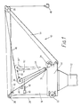
- Fig. 1 is a schematic elevation of a crane according to the invention, and
- Figs. 2 and 3 are simple vector diagrams showing the force acting on the second pulley means of the crane of Fig. 1 at the maximum and minimum operating radii of the jib respectively.
- Referring to Fig. 1 of the drawings, a pedestal crane of the type used on offshore platforms is indicated generally at 10 and includes a support structure consisting of a
pedestal 12 mounted on the platform (not shown), abase 14 mounted on thepedestal 12 by a slewing mechanism (not shown) and asuperstructure 16 incorporating a cab for the crane operators. - One end of a
jib 18 is pivotally mounted to thebase 14, the other, free end of thejib 18 carrying afirst pulley system 20. Aluffing winch 22 and a load-handling winch 24 are also mounted on thebase 14, one end of aluffing rope 26 being attached to theluffing winch 22, saidrope 26 being reeved between thepulley system 20 and apulley 28 mounted on thesuperstructure 16. The other end of therope 26 is anchored, for example at 30, on thesuperstructure 16 whereby operation of thewinch 22 causes thejib 18 to luff. - The crane further includes a second pulley system indicated generally at 32 and comprising an
elongate member 34 one end of which is pivotally mounted to thebase 14 at 36 and the other, free end of which carries apulley 38. - The
member 34 is anchored to aload cell 40 mounted on thesuperstructure 16 through acoil spring 42 reacting between a point on themember 34 adjacent its free end and theload cell 40, amicroswitch 44 being associated with thespring 42 as will be explained in more detail below. - One end of a load-
handling rope 46 is attached to thewinch 24 and is reeved through thesecond pulley system 32 and then through thefirst pulley system 20, the rope terminating at its other end in a load-engaging means such as ahook 48. It should be noted that thepulley system 20 can be any suitable arrangement, and, for example, the pulley or pulleys through which therope 46 is reeved may not be coaxial with the pulleys through which therope 26 is reeved. - As mentioned above, the maximum load the crane can handle is dependent upon the angle of the
jib 18 to the horizontal. For example, with thejib 18 substantially vertical, the crane may be capable of handling a maximum load of 30 tons on thehook 48, while, with the jib substantially horizontal, this load may be reduced to about 10 tons. - For any given load, a tension is set up in the
rope 46 and this is exerted on thepulley system 32 at thepulley 38. - The dimensions and configuration of the pulley system 32 - i.e. the location of the
pivot point 36 and of thecell 40 and spring 42 - are selected such that, regardless of the angle of thejib 18 with the horizontal, the resultant force on thepulley system 32 and therefore on theload cell 40 for a maximum safe load on the crane is substantially constant. - More particularly, and referring to Fig. 2 by way of example only, the maximum load capable of being lifted by the
jib 18 at a relatively acute angle of the jib, indicated by thelines rope 46 to thepulley system 20 and thewinch 24 respectively, is 10 tons. The resultant of these forces in thelines load cell 40. - Similarly and referring to Fig. 3, the maximum load capable of being lifted with the
jib 18 substantially vertically may be 30 tons as indicated by thelines 46P′ and 46W′. The nature of thepulley system 32 is such that the resultant force, indicated by the vector R′, is again 15 tons acting at theload cell 40. - This situation exists for all maximum loads between these two extreme positions of the
jib 18, the resultant force on theload cell 40 always being substantially 15 tons. - Thus it will be appreciated that, for the maximum safe load on the crane at any given operating radius of the
jib 18, a substantially constant predetermined force is exerted on theload cell 40 by way of thespring 42 reacting between that cell and themember 34 of thepulley system 32. - The crane operator can therefore easily read from the load cell output whether or not the load being lifted at the particular radius concerned - i.e. jib elevation - exceeds the permitted safe load. If the permitted safe load is exceeded, the
member 38 extends thespring 42 sufficiently for themicroswitch 44 to be actuated to trigger an associated audible and/or visible alarm or to deactivate thewinch 24. - Such an arrangement utilises the tension in the
rope 46 to produce a modulating signal which is fed to theload cell 40 to ensure that, regardless of the angle of the jib and without the necessity for calculation, overload is detected. The mechanism of the crane itself is thus being used to regulate the load on thepulley system 32. - In a modification of the described embodiment, the
pulley system 32 can function as a rope accumulator system. In such a case, theelongate member 34 is anchored to thesuperstructure 16 through a spring such as 42 which may or may not react against aload cell 40, the load on thespring 42 again being substantially constant for the maximum safe load the crane can lift at any given operating radius of thejib 18. - If, however, the maximum force is exceeded, for example by attempting to lift too great a load at a given jib radius, or inadvertently hooking the ship's superstructure, then the
spring 42 is overcome and thepulley 38, together with theelongate member 34, pivots along anarcuate path 50 to the position shown in dotted lines at 38′ thereby rapidly paying out rope in a sense to reduce the force. Although the amount of rope held in reserve by thesystem 32 is limited, the paying out of the reserve of rope serves to protect thecrane 10 against the effects of the exessive load for a short period which allows the control system (which includes overload sensors) or the operators to respond and cause thewinch 24 to pay out rope. - Modifications and variations to the described and illustrated arrangements can be made without departing from the scope of the invention. For example, the
pulley 38 may be mounted on a slide mechanism, while the resiliency of thesystem 32 in its rope accumulator mode may be provided by pressurised pneumatic, hydraulic or hydropneumatic systems.
Claims (9)
1. A crane comprising a support structure (12,14,16), a jib (18) and a winch (24) mounted on said structure, a rope (46) extending from said winch (24) over first pulley means (20) mounted on the jib (18), the rope (46) terminating in load-engaging means (48), and load-sensing means (40,42) responsive to the load on said rope (46), characterised by second pulley means (32) mounted on the structure (12,14,16), the rope (46) extending from the winch (24) over said second pulley means (32) and then over said first pulley means (20), the load-sensing means (40,42) reacting between the second pulley means (32) and the structure (16) and being so arranged that, for the maximum safe load at any given operating radius of the jib (18), the load-sensing means (40,42) experiences a substantially constant predetermined load thereon.
2. A crane as claimed in claim 1 in which the load-sensing means comprises a load cell (40).
3. A crane as claimed in claim 2 in which the load-sensing means further comprises resilient means (42) and a switch (44) whereby loads in excess of said predetermined load cause sufficient movement of said resilient means (42) to result in operation of the switch (44).
4. A crane as claimed in claim 3 in which the load cell (40) is mounted in series with the resilient means (42).
5. A crane as claimed in claim 1 in which the load-sensing means comprises resilient means (42).
6. A crane as claimed in any one of claims 3 to 5 in which the resilient means comprises a spring (42).
7. A crane as claimed in any one of claims 1 to 6 in which the second pulley means (32) comprises an elongate member (34) one end of which is pivotally mounted (36) on the structure (14) and the other, free end of which carries a pulley (38).
8. A crane as claimed in any one of claims 1 to 6 in which the second pulley means (32) comprises a slide mechanism on which a pulley (38) is mounted.
9. A crane as claimed in any one of claims 3 to 8 in which the resilient means (42) are overcome when the force experienced by the second pulley means (32) exceeds said predetermined load to allow the second pulley means (32) to move in a sense to pay out rope.
Applications Claiming Priority (4)
| Application Number | Priority Date | Filing Date | Title |
|---|---|---|---|
| GB888819960A GB8819960D0 (en) | 1988-08-23 | 1988-08-23 | Cranes |
| GB8819960 | 1988-08-23 | ||
| GB888819959A GB8819959D0 (en) | 1988-08-23 | 1988-08-23 | Cranes |
| GB8819959 | 1988-08-23 |
Publications (1)
| Publication Number | Publication Date |
|---|---|
| EP0358343A1 true EP0358343A1 (en) | 1990-03-14 |
Family
ID=26294311
Family Applications (1)
| Application Number | Title | Priority Date | Filing Date |
|---|---|---|---|
| EP89308173A Withdrawn EP0358343A1 (en) | 1988-08-23 | 1989-08-11 | Crane with overload detector |
Country Status (2)
| Country | Link |
|---|---|
| EP (1) | EP0358343A1 (en) |
| NO (1) | NO893352L (en) |
Cited By (2)
| Publication number | Priority date | Publication date | Assignee | Title |
|---|---|---|---|---|
| US6145680A (en) * | 1997-09-24 | 2000-11-14 | Kci Konecranes International Plc | Apparatus for reducing overload and dampening collision energy |
| CN104150359A (en) * | 2014-07-08 | 2014-11-19 | 湖南中联重科智能技术有限公司 | Hoisting-weight measuring method, equipment, system and engineering machine |
Citations (5)
| Publication number | Priority date | Publication date | Assignee | Title |
|---|---|---|---|---|
| NL89303C (en) * | 1900-01-01 | |||
| DE1167501B (en) * | 1962-10-09 | 1964-04-09 | Demag Ag | Load moment and overload protection for luffing cranes |
| FR1574384A (en) * | 1968-07-11 | 1969-07-11 | ||
| FR2040948A5 (en) * | 1969-04-29 | 1971-01-22 | Schwermasch Dimitroff | |
| FR2162997A5 (en) * | 1971-11-23 | 1973-07-20 | Kirow Leipzig Schwermasc |
-
1989
- 1989-08-11 EP EP89308173A patent/EP0358343A1/en not_active Withdrawn
- 1989-08-21 NO NO89893352A patent/NO893352L/en unknown
Patent Citations (5)
| Publication number | Priority date | Publication date | Assignee | Title |
|---|---|---|---|---|
| NL89303C (en) * | 1900-01-01 | |||
| DE1167501B (en) * | 1962-10-09 | 1964-04-09 | Demag Ag | Load moment and overload protection for luffing cranes |
| FR1574384A (en) * | 1968-07-11 | 1969-07-11 | ||
| FR2040948A5 (en) * | 1969-04-29 | 1971-01-22 | Schwermasch Dimitroff | |
| FR2162997A5 (en) * | 1971-11-23 | 1973-07-20 | Kirow Leipzig Schwermasc |
Cited By (3)
| Publication number | Priority date | Publication date | Assignee | Title |
|---|---|---|---|---|
| US6145680A (en) * | 1997-09-24 | 2000-11-14 | Kci Konecranes International Plc | Apparatus for reducing overload and dampening collision energy |
| CN104150359A (en) * | 2014-07-08 | 2014-11-19 | 湖南中联重科智能技术有限公司 | Hoisting-weight measuring method, equipment, system and engineering machine |
| CN104150359B (en) * | 2014-07-08 | 2016-06-08 | 湖南中联重科智能技术有限公司 | Hoisting capacity measuring method, equipment, system and engineering machinery |
Also Published As
| Publication number | Publication date |
|---|---|
| NO893352L (en) | 1990-02-26 |
| NO893352D0 (en) | 1989-08-21 |
Similar Documents
| Publication | Publication Date | Title |
|---|---|---|
| US5160055A (en) | Load moment indicator system | |
| US4752012A (en) | Crane control means employing load sensing devices | |
| US10472214B2 (en) | Crane and method for monitoring the overload protection of such a crane | |
| US5711440A (en) | Suspension load and tipping moment detecting apparatus for a mobile crane | |
| US6843383B2 (en) | Jib load limiting device | |
| US10597266B2 (en) | Crane and method for monitoring the overload protection of such a crane | |
| US4251059A (en) | Apparatus for determining the reeving of a pulley system | |
| US3854128A (en) | Safety device for crane | |
| US6044991A (en) | Load measuring apparatus for aerial booms and jibs | |
| WO1998055388A1 (en) | Safety monitoring apparatus | |
| EP0358343A1 (en) | Crane with overload detector | |
| US4121293A (en) | Indication means for indicating suitable conditions for the transfer of loads between two stations movable relative to each other in a vertical plane | |
| US8910806B2 (en) | Method for controlling a hoisting or paying out movement and hoisting frame having tiltable cable shreave for use therein | |
| JP2001089078A (en) | Crane overload preventive device, and its regulating method | |
| KR102322167B1 (en) | Mooring rope tension monitoring system | |
| US4252243A (en) | Crane safety device | |
| JP2873498B2 (en) | Boom-type work vehicle safety device | |
| JP2664863B2 (en) | Crane overload prevention device | |
| JP2923078B2 (en) | How to calculate the number of ropes in a crane | |
| EP1491485B1 (en) | Crane with a winch and a traction control device | |
| RU2149820C1 (en) | Device for determination of load on cargo gripping member of boom crane | |
| SU624877A1 (en) | Load capacity limiting device | |
| JP2511607Y2 (en) | Crane jib misoperation prevention device | |
| JPH04235896A (en) | Monitoring system for load lifted by crane and hook device for crane | |
| FI83205C (en) | ANORDING FOER SKYDD AV LASTLYFTMEKANISMER MOT OEVERBELASTNING OCH VAENDNING. |
Legal Events
| Date | Code | Title | Description |
|---|---|---|---|
| PUAI | Public reference made under article 153(3) epc to a published international application that has entered the european phase |
Free format text: ORIGINAL CODE: 0009012 |
|
| AK | Designated contracting states |
Kind code of ref document: A1 Designated state(s): AT DE GB NL SE |
|
| 17P | Request for examination filed |
Effective date: 19900727 |
|
| STAA | Information on the status of an ep patent application or granted ep patent |
Free format text: STATUS: THE APPLICATION HAS BEEN WITHDRAWN |
|
| 18W | Application withdrawn |
Withdrawal date: 19901211 |
|
| R18W | Application withdrawn (corrected) |
Effective date: 19901211 |