EP0358268B1 - Method of and device for correcting scattered-radiation effects in X-ray images - Google Patents
Method of and device for correcting scattered-radiation effects in X-ray images Download PDFInfo
- Publication number
- EP0358268B1 EP0358268B1 EP89202211A EP89202211A EP0358268B1 EP 0358268 B1 EP0358268 B1 EP 0358268B1 EP 89202211 A EP89202211 A EP 89202211A EP 89202211 A EP89202211 A EP 89202211A EP 0358268 B1 EP0358268 B1 EP 0358268B1
- Authority
- EP
- European Patent Office
- Prior art keywords
- image
- matrix
- intensity
- ray
- elements
- Prior art date
- Legal status (The legal status is an assumption and is not a legal conclusion. Google has not performed a legal analysis and makes no representation as to the accuracy of the status listed.)
- Expired - Lifetime
Links
Images
Classifications
-
- H—ELECTRICITY
- H05—ELECTRIC TECHNIQUES NOT OTHERWISE PROVIDED FOR
- H05G—X-RAY TECHNIQUE
- H05G1/00—X-ray apparatus involving X-ray tubes; Circuits therefor
- H05G1/08—Electrical details
- H05G1/64—Circuit arrangements for X-ray apparatus incorporating image intensifiers
-
- H—ELECTRICITY
- H04—ELECTRIC COMMUNICATION TECHNIQUE
- H04N—PICTORIAL COMMUNICATION, e.g. TELEVISION
- H04N5/00—Details of television systems
- H04N5/30—Transforming light or analogous information into electric information
- H04N5/32—Transforming X-rays
- H04N5/3205—Transforming X-rays using subtraction imaging techniques
-
- Y—GENERAL TAGGING OF NEW TECHNOLOGICAL DEVELOPMENTS; GENERAL TAGGING OF CROSS-SECTIONAL TECHNOLOGIES SPANNING OVER SEVERAL SECTIONS OF THE IPC; TECHNICAL SUBJECTS COVERED BY FORMER USPC CROSS-REFERENCE ART COLLECTIONS [XRACs] AND DIGESTS
- Y10—TECHNICAL SUBJECTS COVERED BY FORMER USPC
- Y10S—TECHNICAL SUBJECTS COVERED BY FORMER USPC CROSS-REFERENCE ART COLLECTIONS [XRACs] AND DIGESTS
- Y10S128/00—Surgery
- Y10S128/92—Computer assisted medical diagnostics
- Y10S128/922—Computer assisted medical diagnostics including image analysis
Definitions
- the invention relates to a method of correcting scattered-radiation effects in an X-ray image
- a digital image signal originating from an X-ray system is converted into an image matrix of intensity values which are transformed, into a transformed image matrix, by convolution of the image signal with a point spread function, a scatter image matrix being formed by multiplication of each matrix element of the transformed image matrix by a weighting factor, a corrected image matrix being formed by subtracting matrix elements of the scatter image matrix from corresponding matrix elements of the image matrix.
- the invention also relates to a device for correcting scattered radiation effects in an X-ray image, comprising an X-ray source, an X-ray detector for converting an image-carrying X-ray beam into a video signal, an analog-to-digital converter whose input signal is formed by the video signal and whose output signal is a digital image signal, a transformation device for forming an image matrix of intensity values from the digital image signal and for transforming the image matrix into a transformed image matrix by convolution with a point spread function, a memory device for determining a weighting factor which depends on a local intensity value, and a device for subtracting the transformed image, weighted by weighting factors, from the image matrix.
- This publication describes a method of processing an X-ray image by estimating a scattered radiation field from a spatial intensity distribution of an attenuated X-ray beam.
- This method serves to reconstruct a corrected image having a higher contrast by subtracting a scattered radiation image from the measured intensity distribution from an original image which has been "contaminated" by a non-imaging component which becomes apparent as blurring across the image.
- a linear relationship exists between a logarithm of intensity and the distance in a direction of irradiation.
- a spatial intensity distribution of an X-ray beam attenuated by an object contains a component which does not contribute to imaging, inter alia because in addition to attenuation of the X-ray beam in the propagation direction also scattering on electrons from the attenuating object occurs.
- the intensity distribution of the scattered X-rays can be described as a convolution of a primary incident beam with a so-called point spread function.
- the detected intensity is taken as an estimate for the primary intensity. Any practical image of an object is spatially spread by a point spread function.
- the convoluted primary beam when estimating the scattered radiation from the primary beam, the convoluted primary beam must also be weighted by a weighting factor which depends on the local transmission.
- the accuracy of an estimate of the scattered radiation field is inter alia dependent on the accuracy with which the local weighting factor can be determined.
- the local weighting factor is measured with a fixed setting of a tube voltage of an X-ray tube and a fixed distance between focus and detector. In a correction circuit the local weighting factors are plotted in a table. Dependeing on an intensity value of an element in the image matrix of the detected X-ray image, a local weighting factor is selected whereby a corresponding matrix element of the convoluted image matrix is multiplied.
- a method of this kind has the drawback that the local weighting factor is applicable only to one fixed adjustment value of the imaging parameters.
- a tube voltage, a tube current, a position of the X-ray focus, the patient table, a distance between the patient and the image intensifier, an active cross-section of an entrance screen of an image intensifier, etc. is changed, a new variation of the local weighting factor must be measured.
- the weighting factors may vary comparatively strongly over a short distance in the image. This causes gradients in the estimated scattered radiation image; this is a poor approximation of an actual scattered radiation image which varies only slowly as a function of location.
- a method in accordance with the invention is characterized in that the selection of the weighting factor for an image element of the transformed image matrix is determined by an intensity value of the matrix element of the transformed image matrix.
- the transformed image matrix is a spread version of the image matrix wherefrom comparatively high frequencies have been removed by averaging.
- a weighting factor associated with an image element of the transformed image matrix is selected from a table containing pairs of numbers formed by intensity values of the transformed image matrix and associated weighting factor the spatial variation of the weighting factors is comparatively small.
- a preferred version of a method in accordance with the invention is characterized in that a variation of the weighting factor as a function of the intensity is co-determined by adjustment values of imaging parameters of the X-ray system. Automatic adaptation of the weighting factor to the adjustment values of the imaging parameters eliminates the necessity to determine the weighting factor each time again.
- a further preferred version of a method in accordance with the invention is characterized in that a vertical offset of the weighting factor as a function of the intensity varies linearly with a mean image intensity.
- the weighting factor presenting the local ratio of the intensity of the scattered radiation component to the convoluted primary intensity
- a vertical offset of the variation of the weighting factor with the intensity is determined to a high degree by a "common" adjustment, and in the case of pulsed operation the pulse duration, of tube voltage and tube current of an X-ray tube, a distance between an object to be irradiated and an entrance screen of an X-ray detector, for example an X-ray intensifier, the presence of a scattered radiation grid and the surface area of a detecting surface.
- the setting or pulse duration of the voltage and current of the X-ray tube depends on the thickness of the patient, the scattered radiation component also being dependent thereon.
- the vertical offset can be described as a substantially linear function of the mean image intensity.
- the effect of variations of the image intensity around the mean image intensity on the vertical offset may be taken into account, if desired, as a higher-order effect.
- the presence of a scattered radiation grid has an effect on the vertical offset, which offset is higher in the absence of a scattered radiation grid.
- the vertical offset is lower than for an entrance screen having a comparatively large diameter and the associated wider X-ray beam, because a narrow X-ray beam generates less scattered radiation.
- the weighting factor is not constant but varies across an image plane. This is due to a number of effects.
- a scattered radiation grid is usually more effective at the edges than in the centre.
- a substantial contribution is made to the variation of the image brightness by the fact that a point at an edge of an image plane receives substantially less scattered radiation than a point which is situated nearer to the centre of the image plane.
- the path travelled by the X-rays between an object to be examined and the X-ray detector is longer at the edges of the image than in the centre of the image, so that the relative contribution of the scattered radiation is smaller at the edges than in the centre.
- a further preferred version of a method in accordance with the invention is characterized in that during convolution with the point spread function of an image section which is situated within a distance equal to one half width of the point spread function from an image edge of an image-carrying image, incorrect averaging of said image section is substantially compensated for by multiplication of elements of the scatter image matrix by corresponding elements of a spatial correction matrix.
- the image points which are situated within one half width of the point spread function from the image edge will obtain an incorrect value. This is because averaging takes place with image points which are situated outside the image edge and an intensity value of which can be given an arbitrary value.
- these image points can be scaled to a correct mean value. This can be realised, for example by convoluting an entirely white image with the point spread function and by taking the intensity values which are not equal to zero as the scale value.
- the scatter image matrix is multiplied by a correction matrix formed by the inverse scale values, the edge points are scaled back again to their original mean value.
- the correction matrix can be included in the spatial correction matrix.
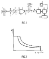
- Fig. 1 shows an X-ray tube 1 comprising a rotary anode 3.
- the anode 3 emits an X-ray beam 5 which is collimated by a collimator 7 and which is detected by an X-ray image intensifier tube 9 after having irradiated an object 8.
- An entrance screen 11 of the X-ray image intensifier tube 9 comprises a scattered radiation grid 10 which intercepts a part of the X-rays having a propagation direction which deviates from that of the direction of irradiation.
- an image-carrying X-ray beam 5 is converted into an image-carrying light beam 13.
- a semitransparent mirror 15 splits the light beam 13 into a part which is imaged on a photographic film by a photo camera 17, and a part which is converted into a video signal by a television camera device 19.
- the video signal is digitised by an ADC 21; in a correction circuit 22 the video signal is corrected so as to eliminate the scattered radiation effects from the X-ray image.
- the correction circuit 22 receives adjustment values for image parameters from a read unit 23, for example voltage and current of the X-ray tube 1 and the distance between the object 8 and the entrance screen 11, etc.
- the corrected image signal can be displayed on a television monitor 25.
- Fig. 2 shows the variation of the weighting factor as a function of the image intensity.
- the vertical offset of the curve is co-determined by the thickness of the object 8 for which the adjustment values of current and voltage of the X-ray tube 1 are a measure.
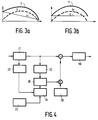
- Fig. 3a shows a curve a which represents the distribution of the correction values for a row of matrix elements of the spatial correction matrix.
- the scattered radiation makes a largest contribution near the centre of this row and its effect decreases in the direction of the edges in accordance with the curve b .
- the correction values are represented by the superposition of a curve b and a curve c , with a distribution which decreases from one image edge to an oppositely situated image edge.
- Fig. 3b shows the distribution of the correction values for a column of matrix elements of the spatial correction matrix.
- the heel effect varies in only one direction and is constant for columns of the correction matrix (curve c).
- Fig. 4 shows the ADC 21 in which a video signal is digitised.
- a mean image intensity is determined which is used, together with adjustment values of the imaging parameters and the system variables which originate from a read unit 23, to generate a weighting factor function in an arithmetic and memory unit 34.
- a memory unit 36 pairs of numbers, formed by total intensity values and the associated intensity value of the scattered radiation, are stored in the form of a table.
- a scattered radiation intensity For each element of the transformed image matrix determined in the transformation unit 32 there is determined a scattered radiation intensity. After multiplication of the elements of the scattered image matrix by corresponding elements of a spatial correction matrix in a spatial correction unit 38, the corrected image matrix is substracted from the original image matrix.
- the corrected image signal can be converted into an analog signal by a DAC 40 for display on a television monitor.
Description
- The invention relates to a method of correcting scattered-radiation effects in an X-ray image where a digital image signal originating from an X-ray system is converted into an image matrix of intensity values which are transformed, into a transformed image matrix, by convolution of the image signal with a point spread function, a scatter image matrix being formed by multiplication of each matrix element of the transformed image matrix by a weighting factor, a corrected image matrix being formed by subtracting matrix elements of the scatter image matrix from corresponding matrix elements of the image matrix.
- The invention also relates to a device for correcting scattered radiation effects in an X-ray image, comprising an X-ray source, an X-ray detector for converting an image-carrying X-ray beam into a video signal, an analog-to-digital converter whose input signal is formed by the video signal and whose output signal is a digital image signal, a transformation device for forming an image matrix of intensity values from the digital image signal and for transforming the image matrix into a transformed image matrix by convolution with a point spread function, a memory device for determining a weighting factor which depends on a local intensity value, and a device for subtracting the transformed image, weighted by weighting factors, from the image matrix.
- A method of this kind is known from Med. Phys., Vol. 14, No. 3, May/June 1987, pp. 330-334.
- This publication describes a method of processing an X-ray image by estimating a scattered radiation field from a spatial intensity distribution of an attenuated X-ray beam. This method serves to reconstruct a corrected image having a higher contrast by subtracting a scattered radiation image from the measured intensity distribution from an original image which has been "contaminated" by a non-imaging component which becomes apparent as blurring across the image. In the absence of scattered radiation, a linear relationship exists between a logarithm of intensity and the distance in a direction of irradiation. By correction for scattered radiation the quantitative accuracy increases in densitometry where relative thickness differences are calculated from an image. A spatial intensity distribution of an X-ray beam attenuated by an object contains a component which does not contribute to imaging, inter alia because in addition to attenuation of the X-ray beam in the propagation direction also scattering on electrons from the attenuating object occurs. The intensity distribution of the scattered X-rays can be described as a convolution of a primary incident beam with a so-called point spread function. The detected intensity is taken as an estimate for the primary intensity. Any practical image of an object is spatially spread by a point spread function. Because a ratio of scattered radiation to primary radiation behind a thick object when irradiated by an X-ray beam is higher than that behind a thin object, when estimating the scattered radiation from the primary beam, the convoluted primary beam must also be weighted by a weighting factor which depends on the local transmission. The accuracy of an estimate of the scattered radiation field is inter alia dependent on the accuracy with which the local weighting factor can be determined. In the cited publication the local weighting factor is measured with a fixed setting of a tube voltage of an X-ray tube and a fixed distance between focus and detector. In a correction circuit the local weighting factors are plotted in a table. Dependeing on an intensity value of an element in the image matrix of the detected X-ray image, a local weighting factor is selected whereby a corresponding matrix element of the convoluted image matrix is multiplied.
- A method of this kind has the drawback that the local weighting factor is applicable only to one fixed adjustment value of the imaging parameters. When a tube voltage, a tube current, a position of the X-ray focus, the patient table, a distance between the patient and the image intensifier, an active cross-section of an entrance screen of an image intensifier, etc. is changed, a new variation of the local weighting factor must be measured. Furthermore, during determination of the local weighting factor from the detected image, which may contain abrupt transition in brightness, the weighting factors may vary comparatively strongly over a short distance in the image. This causes gradients in the estimated scattered radiation image; this is a poor approximation of an actual scattered radiation image which varies only slowly as a function of location.
- It is an object of the invention to provide a method of correcting scattered radiation effects in an X-ray image which avoids said drawbacks.
- To achieve this, a method in accordance with the invention is characterized in that the selection of the weighting factor for an image element of the transformed image matrix is determined by an intensity value of the matrix element of the transformed image matrix.
- The transformed image matrix is a spread version of the image matrix wherefrom comparatively high frequencies have been removed by averaging. When a weighting factor associated with an image element of the transformed image matrix is selected from a table containing pairs of numbers formed by intensity values of the transformed image matrix and associated weighting factor the spatial variation of the weighting factors is comparatively small.
- A preferred version of a method in accordance with the invention is characterized in that a variation of the weighting factor as a function of the intensity is co-determined by adjustment values of imaging parameters of the X-ray system. Automatic adaptation of the weighting factor to the adjustment values of the imaging parameters eliminates the necessity to determine the weighting factor each time again.
- A further preferred version of a method in accordance with the invention is characterized in that a vertical offset of the weighting factor as a function of the intensity varies linearly with a mean image intensity.
- It is known that for a decreasing thickness of an irradiated object the weighting factor, presenting the local ratio of the intensity of the scattered radiation component to the convoluted primary intensity, decreases. A vertical offset of the variation of the weighting factor with the intensity is determined to a high degree by a "common" adjustment, and in the case of pulsed operation the pulse duration, of tube voltage and tube current of an X-ray tube, a distance between an object to be irradiated and an entrance screen of an X-ray detector, for example an X-ray intensifier, the presence of a scattered radiation grid and the surface area of a detecting surface. The setting or pulse duration of the voltage and current of the X-ray tube depends on the thickness of the patient, the scattered radiation component also being dependent thereon. For tube voltages of between 50 kV and 70 kV and a distance of between 5 and 20 cm between the object to be irradiated and an entrance screen of an X-ray detector, the vertical offset can be described as a substantially linear function of the mean image intensity. The effect of variations of the image intensity around the mean image intensity on the vertical offset may be taken into account, if desired, as a higher-order effect. The presence of a scattered radiation grid has an effect on the vertical offset, which offset is higher in the absence of a scattered radiation grid. For an entrance screen of an X-ray detector having a comparatively small diameter and for the associated X-ray beam collimated to a narrow beam, the vertical offset is lower than for an entrance screen having a comparatively large diameter and the associated wider X-ray beam, because a narrow X-ray beam generates less scattered radiation.
- When a homogeneous object having comparatively large transverse dimensions is irradiated, the weighting factor is not constant but varies across an image plane. This is due to a number of effects. A scattered radiation grid is usually more effective at the edges than in the centre. However, a substantial contribution is made to the variation of the image brightness by the fact that a point at an edge of an image plane receives substantially less scattered radiation than a point which is situated nearer to the centre of the image plane. Because of the beam geometry and the curvature of the entrance screen of the detector, the path travelled by the X-rays between an object to be examined and the X-ray detector is longer at the edges of the image than in the centre of the image, so that the relative contribution of the scattered radiation is smaller at the edges than in the centre. Due to the shape of an anode of an X-ray tube the intensity and the hardness of the radiation vary from one side of the image to another side (the so-called "heel effect"). Consequently, the relative contribution of the scattered radiation varies. By multiplication of the elements of the scatter image matrix by corresponding elements of the spatial correction matrix, image correction can be performed to reduce the image inhomogeneities thus caused.
- A further preferred version of a method in accordance with the invention is characterized in that during convolution with the point spread function of an image section which is situated within a distance equal to one half width of the point spread function from an image edge of an image-carrying image, incorrect averaging of said image section is substantially compensated for by multiplication of elements of the scatter image matrix by corresponding elements of a spatial correction matrix.
- Upon convolution of the image signal with the point spread function so that the intensity value in each image point is obtained by a weighted average with intensity values of neighbouring image points, the image points which are situated within one half width of the point spread function from the image edge will obtain an incorrect value. This is because averaging takes place with image points which are situated outside the image edge and an intensity value of which can be given an arbitrary value. Using a spatial correction, these image points can be scaled to a correct mean value. This can be realised, for example by convoluting an entirely white image with the point spread function and by taking the intensity values which are not equal to zero as the scale value. When the scatter image matrix is multiplied by a correction matrix formed by the inverse scale values, the edge points are scaled back again to their original mean value. The correction matrix can be included in the spatial correction matrix.
- Some versions of a method in accordance with the invention will be described in detail hereinafter with reference to the accompanying drawing; therein
- Fig. 1 shows an X-ray examination apparatus for performing the method of correcting scattered-radiation effects in an X-ray image,
- Fig. 2 shows the weighting factor as a function of the image intensity,
- Fig. 3 shows a spatial correction along two mutually perpendicular image lines, and
- Fig. 4 is a diagrammatic representation of a correction circuit.
- Fig. 1 shows an
X-ray tube 1 comprising a rotary anode 3. The anode 3 emits anX-ray beam 5 which is collimated by acollimator 7 and which is detected by an X-rayimage intensifier tube 9 after having irradiated anobject 8. Anentrance screen 11 of the X-rayimage intensifier tube 9 comprises ascattered radiation grid 10 which intercepts a part of the X-rays having a propagation direction which deviates from that of the direction of irradiation. In the X-ray image intensifier tube an image-carryingX-ray beam 5 is converted into an image-carryinglight beam 13. A semitransparent mirror 15 splits thelight beam 13 into a part which is imaged on a photographic film by aphoto camera 17, and a part which is converted into a video signal by atelevision camera device 19. The video signal is digitised by anADC 21; in acorrection circuit 22 the video signal is corrected so as to eliminate the scattered radiation effects from the X-ray image. Thecorrection circuit 22 receives adjustment values for image parameters from aread unit 23, for example voltage and current of theX-ray tube 1 and the distance between theobject 8 and theentrance screen 11, etc. The corrected image signal can be displayed on atelevision monitor 25. - Fig. 2 shows the variation of the weighting factor as a function of the image intensity. The vertical offset of the curve is co-determined by the thickness of the
object 8 for which the adjustment values of current and voltage of theX-ray tube 1 are a measure. - Fig. 3a shows a curve a which represents the distribution of the correction values for a row of matrix elements of the spatial correction matrix. The scattered radiation makes a largest contribution near the centre of this row and its effect decreases in the direction of the edges in accordance with the curve b. Because of the "heel" effect the correction values are represented by the superposition of a curve b and a curve c, with a distribution which decreases from one image edge to an oppositely situated image edge.
- Fig. 3b shows the distribution of the correction values for a column of matrix elements of the spatial correction matrix. The heel effect varies in only one direction and is constant for columns of the correction matrix (curve c).
- Fig. 4 shows the
ADC 21 in which a video signal is digitised. In an averaging device 30 a mean image intensity is determined which is used, together with adjustment values of the imaging parameters and the system variables which originate from aread unit 23, to generate a weighting factor function in an arithmetic andmemory unit 34. In amemory unit 36 pairs of numbers, formed by total intensity values and the associated intensity value of the scattered radiation, are stored in the form of a table. For each element of the transformed image matrix determined in thetransformation unit 32 there is determined a scattered radiation intensity. After multiplication of the elements of the scattered image matrix by corresponding elements of a spatial correction matrix in a spatial correction unit 38, the corrected image matrix is substracted from the original image matrix. The corrected image signal can be converted into an analog signal by aDAC 40 for display on a television monitor.
Claims (9)
- A method of correcting scattered radiation effects in an X-ray image where a digital image signal originating from an X-ray system is converted into an image matrix of intensity values which are transformed into a transformed image matrix by convolution of the image signal with a point spread function, a scatter image matrix being formed by multiplication of each matrix element of the transformed image matrix by a weighting factor, a corrected image matrix being formed by subtracting matrix elements of the scatter image matrix from corresponding matrix elements of the image matrix, characterized in that the selection of the weighting factor for an image element of the transformed image matrix is determined by an intensity value of the matrix element of the transformed image matrix.
- A method as claimed in Claim 1, characterized in that the weighting factor as a function of the intensity is co-determined by adjustment values of imaging parameters of the X-ray system.
- A method as claimed in Claim 1 or 2, in which the weighting factor as a function of the intensity is given by a monotonously descending function for intensities higher than an intensity I₀, characterized in that a vertical offset of the function varies linearly with a mean image intensity.
- A method as claimed in Claim 1, 2 or 3, characterized in that the elements of the scatter image matrix are multiplied by corresponding elements of a spatial correction matrix.
- A method as claimed in Claim 4, characterized in that matrix elements in a row of the spatial correction matrix exhibit an intensity value distribution which is formed by a function which monotonously descends across an image width and which is superposed on an intensity value distribution which is smaller at the image edges than in the image centre, matrix elements in a column of the spatial correction matrix exhibiting an intensity value distribution which is smaller at the edges of the image than at the centre of the image.
- A method as claimed in Claim 4 or 5, characterized in that during convolution with the point spread function of an image section which is situated within a distance equal to one half width of the point spread function from an image edge of an image-carrying image, incorrect averaging of said image section is substantially compensated for by multiplication of elements of the scatter image matrix by corresponding elements of a spatial correction matrix.
- A device for correcting scattered radiation effects in an X-ray image, comprising an X-ray source, and X-ray detector for converting an image carrying X-ray beam into a video signal, an analog-to-digital converter whose input signal is formed by the video signal and whose output signal is a digital image signal, a transformation device for forming an image matrix of intensity values from the digital image signal and for transforming the image matrix into a transformed image matrix by convolution with a point spread function, a memory device for determining a weighting factor which depends on a local intensity value, and a device for subtracting the transformed image matrix, weighted by weighting factors, from the image matrix, characterized in that the device comprises an averaging device for determining mean image intensity from the digital image signal, and also comprises an arithmetic device whose input signal is formed by the mean image intensity in order to form a table containing pairs of numbers of intensity and associated weighting factor in the memory device for the selection of the weighting factor for an element of the transformed image matrix under the control of an intensity value of the element of the transformed image matrix.
- A device for correcting scattered radiation effects in an X-ray image as claimed in Claim 7, characterized in that an input signal for the arithmetic and memory device contains adjustment values for the imaging parameters in order to calculate the weighting factors.
- A device for correcting scattered radiation effects in an X-ray image as claimed in Claim 7 or 8, characterized in that the device comprises a device for multiplying the elements of the transformed image matrix by corresponding matrix elements of a spatial correction matrix.
Applications Claiming Priority (2)
| Application Number | Priority Date | Filing Date | Title |
|---|---|---|---|
| NL8802184 | 1988-09-05 | ||
| NL8802184A NL8802184A (en) | 1988-09-05 | 1988-09-05 | METHOD AND APPARATUS FOR CORRECTION OF SPREAD RADIATION EFFECTS IN ROENTGEN IMAGES. |
Publications (2)
| Publication Number | Publication Date |
|---|---|
| EP0358268A1 EP0358268A1 (en) | 1990-03-14 |
| EP0358268B1 true EP0358268B1 (en) | 1993-12-01 |
Family
ID=19852856
Family Applications (1)
| Application Number | Title | Priority Date | Filing Date |
|---|---|---|---|
| EP89202211A Expired - Lifetime EP0358268B1 (en) | 1988-09-05 | 1989-09-01 | Method of and device for correcting scattered-radiation effects in X-ray images |
Country Status (5)
| Country | Link |
|---|---|
| US (1) | US5270925A (en) |
| EP (1) | EP0358268B1 (en) |
| JP (2) | JP3110026B2 (en) |
| DE (1) | DE68911072T2 (en) |
| NL (1) | NL8802184A (en) |
Cited By (1)
| Publication number | Priority date | Publication date | Assignee | Title |
|---|---|---|---|---|
| KR101443051B1 (en) * | 2013-01-10 | 2014-09-22 | 제이더블유중외메디칼 주식회사 | THE REDUCTION METHOD OF X-ray SCATTER FROM DIGITAL RADIOGRAPHY IMAGE BY IMAGE PROCESSING AND DIGITAL RADIOGRAPHY SYSTEM USING THE SAME |
Families Citing this family (21)
| Publication number | Priority date | Publication date | Assignee | Title |
|---|---|---|---|---|
| JPH05221282A (en) * | 1992-02-14 | 1993-08-31 | Tokai Rika Co Ltd | Vehicle quick deceleration condition detecting device |
| DE69308350T2 (en) * | 1992-04-08 | 1997-08-21 | Philips Electronics Nv | X-ray examination device with correction of scattered radiation effects in an X-ray image |
| EP0565171B1 (en) * | 1992-04-08 | 1997-03-05 | Koninklijke Philips Electronics N.V. | X-ray examination apparatus having means for correcting scattered-radiation effects in an x-ray image |
| FR2759800B1 (en) * | 1997-02-17 | 1999-03-26 | Commissariat Energie Atomique | METHOD FOR CORRECTING THE DIFFUSED FLOW IN DIGITAL RADIOGRAPHY IMAGES |
| FR2766044B1 (en) * | 1997-07-11 | 1999-10-08 | Ge Medical Syst Sa | PROCESS FOR PROCESSING A SEQUENCE OF RADIOLOGICAL IMAGES OF AN OBJECT |
| DE10055739B4 (en) * | 2000-11-10 | 2006-04-27 | Siemens Ag | Scattering correction method for an X-ray computed tomography device |
| DE102005043050A1 (en) * | 2005-09-09 | 2007-03-22 | Siemens Ag | Calibration method and correction method for an X-ray device and an X-ray device for performing such a calibration or. correction method |
| EP1946622A2 (en) * | 2005-10-06 | 2008-07-23 | Imaging Sciences International, Inc. | Scatter correction |
| US8000435B2 (en) * | 2006-06-22 | 2011-08-16 | Koninklijke Philips Electronics N.V. | Method and system for error compensation |
| US7492864B2 (en) * | 2007-01-16 | 2009-02-17 | Siemens Medical Solutions Usa, Inc. | Methods and apparatus for range based X-Ray attenuation |
| WO2008104915A2 (en) * | 2007-02-27 | 2008-09-04 | Philips Intellectual Property & Standards Gmbh | Simulation and visualization of scattered radiation |
| WO2010058329A1 (en) * | 2008-11-21 | 2010-05-27 | Philips Intellectual Property & Standards Gmbh | System and method for x-ray scatter correction |
| WO2010141583A2 (en) * | 2009-06-02 | 2010-12-09 | Mayo Foundation For Medical Education And Research | System and method for dose verification radiotherapy |
| DE102009053664A1 (en) | 2009-11-17 | 2011-05-19 | Ziehm Imaging Gmbh | Method for the empirical determination of a correction function for the correction of radiation hardening and stray radiation effects in projection radiography and in computed tomography |
| US20120163695A1 (en) * | 2010-12-22 | 2012-06-28 | General Electric Company | Intra-detector scatter correction |
| KR101254446B1 (en) * | 2011-07-27 | 2013-04-16 | 심순임 | Method of obtaining x-ray image data and system for the same |
| KR102026735B1 (en) * | 2012-10-02 | 2019-09-30 | 삼성전자주식회사 | Method and apparatus for generating system response of scanner of imaging apparatus and medical image using the same |
| JP6653629B2 (en) * | 2016-06-21 | 2020-02-26 | 富士フイルム株式会社 | Radiation image processing apparatus, method and program |
| CN108065950B (en) * | 2016-11-14 | 2021-05-11 | 通用电气公司 | Radiation imaging method and system thereof |
| KR102399148B1 (en) | 2016-11-25 | 2022-05-19 | 삼성전자주식회사 | X-ray image apparatus and method for obtaining medicalimage thereof |
| DE102020210958A1 (en) | 2020-08-31 | 2022-03-03 | Siemens Healthcare Gmbh | Method for an artifact correction in a reconstruction of at least one slice image from a plurality of projection images |
Family Cites Families (7)
| Publication number | Priority date | Publication date | Assignee | Title |
|---|---|---|---|---|
| GB1577615A (en) * | 1976-05-13 | 1980-10-29 | Emi Ltd | Radiography |
| US4135247A (en) * | 1977-08-15 | 1979-01-16 | Siemens Aktiengesellschaft | Tomography signal processing system |
| GB1602072A (en) * | 1978-05-12 | 1981-11-04 | Emi Ltd | Processing arrangements for constructing representations of parts of bodies |
| GB1602071A (en) * | 1978-05-12 | 1981-11-04 | Emi Ltd | Processing arrangements for medical examination |
| JPS59151940A (en) * | 1983-02-18 | 1984-08-30 | 株式会社東芝 | X-ray diagnostic apparatus |
| US4727562A (en) * | 1985-09-16 | 1988-02-23 | General Electric Company | Measurement of scatter in x-ray imaging |
| US4809172A (en) * | 1987-03-11 | 1989-02-28 | Kabushiki Kaisha Toshiba | Method for obtaining image data with a tomographic apparatus |
-
1988
- 1988-09-05 NL NL8802184A patent/NL8802184A/en not_active Application Discontinuation
-
1989
- 1989-08-21 US US07/397,157 patent/US5270925A/en not_active Expired - Fee Related
- 1989-09-01 EP EP89202211A patent/EP0358268B1/en not_active Expired - Lifetime
- 1989-09-01 DE DE68911072T patent/DE68911072T2/en not_active Expired - Fee Related
- 1989-09-04 JP JP01227639A patent/JP3110026B2/en not_active Expired - Fee Related
-
1999
- 1999-10-20 JP JP11298341A patent/JP3112455B2/en not_active Expired - Fee Related
Cited By (1)
| Publication number | Priority date | Publication date | Assignee | Title |
|---|---|---|---|---|
| KR101443051B1 (en) * | 2013-01-10 | 2014-09-22 | 제이더블유중외메디칼 주식회사 | THE REDUCTION METHOD OF X-ray SCATTER FROM DIGITAL RADIOGRAPHY IMAGE BY IMAGE PROCESSING AND DIGITAL RADIOGRAPHY SYSTEM USING THE SAME |
Also Published As
| Publication number | Publication date |
|---|---|
| US5270925A (en) | 1993-12-14 |
| JP3110026B2 (en) | 2000-11-20 |
| JP2000102526A (en) | 2000-04-11 |
| DE68911072T2 (en) | 1994-05-19 |
| DE68911072D1 (en) | 1994-01-13 |
| JPH02108375A (en) | 1990-04-20 |
| JP3112455B2 (en) | 2000-11-27 |
| EP0358268A1 (en) | 1990-03-14 |
| NL8802184A (en) | 1990-04-02 |
Similar Documents
| Publication | Publication Date | Title |
|---|---|---|
| EP0358268B1 (en) | Method of and device for correcting scattered-radiation effects in X-ray images | |
| EP0223545B1 (en) | Energy dependent gain correction | |
| US7431500B2 (en) | Dynamic exposure control in radiography | |
| JP2719784B2 (en) | Imaging device | |
| JP2606828B2 (en) | X-ray image calibration device | |
| US9672949B2 (en) | X-ray imaging system and image processing method | |
| US6920198B2 (en) | Methods and apparatus for processing a fluoroscopic image | |
| US5774521A (en) | Regularization technique for densitometric correction | |
| KR101850871B1 (en) | Method for processing radiography image and radiography system | |
| WO1991002320A1 (en) | Method and apparatus for computing tomographic scans | |
| Munro et al. | Therapy imaging: a signal‐to‐noise analysis of a fluoroscopic imaging system for radiotherapy localization | |
| EP0689047B1 (en) | Method of compensating for radiation scatter in an x-ray imaging system | |
| Kim et al. | Measurement of the lag correction factor in low-dose fluoroscopic imaging | |
| Chen et al. | Detector response and exposure control of the RadioVisioGraphy system (RVG 32000 ZHR) | |
| JPH05217689A (en) | Method and device for x-ray photographing | |
| Bjorkholm et al. | Digital radiography | |
| JP2020514776A (en) | Method of estimating the radiation dose delivered by a radiology system | |
| US7073941B2 (en) | Radiographic apparatus and radiation detection signal processing method | |
| US7949174B2 (en) | System and method for calibrating an X-ray detector | |
| Bernhardt et al. | Spatial frequency-dependent signal-to-noise ratio as a generalized measure of image quality | |
| Riederer et al. | Three‐beam K‐edge imaging of iodine using differences between fluoroscopic video images: Experimental results | |
| Floyd Jr et al. | Evaluation of a selenium-based digital chest radiography system | |
| Xu et al. | Arbitrary shape region-of-interest fluoroscopy system | |
| EP1351606A2 (en) | Method of calibration of a radiology apparatus and radiology apparatus | |
| JPH0320107B2 (en) |
Legal Events
| Date | Code | Title | Description |
|---|---|---|---|
| PUAI | Public reference made under article 153(3) epc to a published international application that has entered the european phase |
Free format text: ORIGINAL CODE: 0009012 |
|
| AK | Designated contracting states |
Kind code of ref document: A1 Designated state(s): DE ES FR GB IT NL |
|
| 17P | Request for examination filed |
Effective date: 19900911 |
|
| 17Q | First examination report despatched |
Effective date: 19921216 |
|
| GRAA | (expected) grant |
Free format text: ORIGINAL CODE: 0009210 |
|
| AK | Designated contracting states |
Kind code of ref document: B1 Designated state(s): DE ES FR GB IT NL |
|
| PG25 | Lapsed in a contracting state [announced via postgrant information from national office to epo] |
Ref country code: ES Free format text: THE PATENT HAS BEEN ANNULLED BY A DECISION OF A NATIONAL AUTHORITY Effective date: 19931201 |
|
| REF | Corresponds to: |
Ref document number: 68911072 Country of ref document: DE Date of ref document: 19940113 |
|
| ITF | It: translation for a ep patent filed |
Owner name: ING. C. GREGORJ S.P.A. |
|
| ET | Fr: translation filed | ||
| PLBE | No opposition filed within time limit |
Free format text: ORIGINAL CODE: 0009261 |
|
| STAA | Information on the status of an ep patent application or granted ep patent |
Free format text: STATUS: NO OPPOSITION FILED WITHIN TIME LIMIT |
|
| 26N | No opposition filed | ||
| ITPR | It: changes in ownership of a european patent |
Owner name: CAMBIO RAGIONE SOCIALE;PHILIPS ELECTRONICS N.V. |
|
| REG | Reference to a national code |
Ref country code: FR Ref legal event code: CD |
|
| NLT1 | Nl: modifications of names registered in virtue of documents presented to the patent office pursuant to art. 16 a, paragraph 1 |
Owner name: PHILIPS ELECTRONICS N.V. |
|
| PGFP | Annual fee paid to national office [announced via postgrant information from national office to epo] |
Ref country code: NL Payment date: 19950930 Year of fee payment: 7 |
|
| PG25 | Lapsed in a contracting state [announced via postgrant information from national office to epo] |
Ref country code: NL Effective date: 19970401 |
|
| NLV4 | Nl: lapsed or anulled due to non-payment of the annual fee |
Effective date: 19970401 |
|
| REG | Reference to a national code |
Ref country code: FR Ref legal event code: CD |
|
| PGFP | Annual fee paid to national office [announced via postgrant information from national office to epo] |
Ref country code: FR Payment date: 20000925 Year of fee payment: 12 |
|
| PGFP | Annual fee paid to national office [announced via postgrant information from national office to epo] |
Ref country code: GB Payment date: 20000929 Year of fee payment: 12 |
|
| PGFP | Annual fee paid to national office [announced via postgrant information from national office to epo] |
Ref country code: DE Payment date: 20001122 Year of fee payment: 12 |
|
| PG25 | Lapsed in a contracting state [announced via postgrant information from national office to epo] |
Ref country code: GB Free format text: LAPSE BECAUSE OF NON-PAYMENT OF DUE FEES Effective date: 20010901 |
|
| PG25 | Lapsed in a contracting state [announced via postgrant information from national office to epo] |
Ref country code: DE Free format text: LAPSE BECAUSE OF NON-PAYMENT OF DUE FEES Effective date: 20020501 |
|
| PG25 | Lapsed in a contracting state [announced via postgrant information from national office to epo] |
Ref country code: FR Free format text: LAPSE BECAUSE OF NON-PAYMENT OF DUE FEES Effective date: 20020531 |
|
| REG | Reference to a national code |
Ref country code: FR Ref legal event code: ST |
|
| PG25 | Lapsed in a contracting state [announced via postgrant information from national office to epo] |
Ref country code: IT Free format text: LAPSE BECAUSE OF NON-PAYMENT OF DUE FEES;WARNING: LAPSES OF ITALIAN PATENTS WITH EFFECTIVE DATE BEFORE 2007 MAY HAVE OCCURRED AT ANY TIME BEFORE 2007. THE CORRECT EFFECTIVE DATE MAY BE DIFFERENT FROM THE ONE RECORDED. Effective date: 20050901 |