EP0358212A2 - Reactive gas sample introduction system for an inductively coupled plasma torch - Google Patents
Reactive gas sample introduction system for an inductively coupled plasma torch Download PDFInfo
- Publication number
- EP0358212A2 EP0358212A2 EP89116530A EP89116530A EP0358212A2 EP 0358212 A2 EP0358212 A2 EP 0358212A2 EP 89116530 A EP89116530 A EP 89116530A EP 89116530 A EP89116530 A EP 89116530A EP 0358212 A2 EP0358212 A2 EP 0358212A2
- Authority
- EP
- European Patent Office
- Prior art keywords
- sample
- gas
- plasma
- vapor
- flow
- Prior art date
- Legal status (The legal status is an assumption and is not a legal conclusion. Google has not performed a legal analysis and makes no representation as to the accuracy of the status listed.)
- Granted
Links
Images

Classifications
-
- H—ELECTRICITY
- H01—ELECTRIC ELEMENTS
- H01J—ELECTRIC DISCHARGE TUBES OR DISCHARGE LAMPS
- H01J49/00—Particle spectrometers or separator tubes
- H01J49/02—Details
- H01J49/10—Ion sources; Ion guns
- H01J49/105—Ion sources; Ion guns using high-frequency excitation, e.g. microwave excitation, Inductively Coupled Plasma [ICP]
-
- H—ELECTRICITY
- H05—ELECTRIC TECHNIQUES NOT OTHERWISE PROVIDED FOR
- H05H—PLASMA TECHNIQUE; PRODUCTION OF ACCELERATED ELECTRICALLY-CHARGED PARTICLES OR OF NEUTRONS; PRODUCTION OR ACCELERATION OF NEUTRAL MOLECULAR OR ATOMIC BEAMS
- H05H1/00—Generating plasma; Handling plasma
- H05H1/24—Generating plasma
- H05H1/26—Plasma torches
- H05H1/30—Plasma torches using applied electromagnetic fields, e.g. high frequency or microwave energy
Definitions
- This invention relates to a torch system and method for introducing a sample of gas or vapor, such as a reactive gas or vapor, into an inductively coupled plasma for the subsequent analysis of said sample by analytical means, such as a mass spectrometer, a spectroscope or similar analytical means.
- analytical means such as a mass spectrometer, a spectroscope or similar analytical means.
- ICP inductively coupled plasma torch
- This patent is directed to a mass spectrometer in which at least some of the ions formed from a sample introduced into an inductively coupled plasma (ICP) are caused to enter a sampling member comprised of a front surface adjacent to the plasma, a rear surface, and a hole connecting the front and rear surfaces through which at least some of the ions pass.
- ICP inductively coupled plasma
- the spectrometer described in the patent has a chamber in which a wall thereof comprises the rear surface of the sampling member.
- the pressure in the chamber is maintained substantially below atmospheric and at least some of the ions entering the chamber are caused to enter a mass analyzer.
- the improvement in the patent resides in providing the rear surface with a polish finish in order to reduce the intensity of background spectra which prevail in prior instruments and which limit the sensitivity of the instrument to certain elements.
- U.S. Patent No. 3,467,471 relates to the production of a gas plasma and to the spectroscopic examination of the radiation emitted from the plasma from a sample, e.g., a phosphorus-containing sample, introduced into the plasma.
- the spectroscopic examination is used as a means for controlling manufacturing processes which require analysis of raw material or a product.
- U.S. Patent No. 4,551,609 is directed to a plasma burner or torch for emission spectrometry.
- the plasma burner described comprises an induction coil for generating a plasma, an outer jacket, an inner jacket coaxial with the outer jacket and a sleeve coaxially located inside the inner jacket.
- a capillary tube is located inside the sleeve and is oriented along the axis of symmetry.
- the torch or burner is provided with a cooling gas feed line, a plasma gas feed line, and an aerosol gas feed line. According to the patent, the rate of consumption of plasma gas as well as of the cooling gas is reduced, while the detection power of the device for such elements as boron, iron, magnesium, phosphorus and zinc is comparable to conventional plasma torches.
- U.S. Patent No. 4,688,935 is directed to the plasma spectroscopic analysis of organometallic compounds, particularly volatile, air or moisture sensitive or pyrophoric, liquid organometallic compounds.
- the method employed comprises inserting a sample of the compound into a flask referred to as an exponential dilution flask. Substantially the entire sample is allowed to vaporize and the vapor analyzed by plasma spectroscopy.
- Another method is disclosed in which the sample is decomposed by dropwise addition into frozen aqueous acid, diluting the decomposed sample with water and analyzing the diluted, decomposed sample by plasma spectroscopy.
- Nebulization of solutions is a convenient way for sample introduction into an inductively coupled plasma system. It is considered a major step forward in mass spectrometry. Water solutions of the sample to be analyzed are employed. Gas is passed through the nebulizer and entrains the sample as an aerosol which is subsequently introduced into the ICP torch.
- a gas or vapor e.g., a reactive gas or vapor
- Another object is to provide a method for introducing a sample of reactive gas or vapor into a plasma flame while maintaining the integrity of the sample from a composition view point up to its introduction into the plasma flame.
- the invention resides in a torch device wherein the sample, for example, a reactive gas or vapor, is introduced into the torch system without having to pass through the nebulizer but which in the course of passing through the torch is mixed with the nebulizer solution in the form of an aerosol or vapor dispersed in a plasma gas just before it enters the inductively coupled plasma means (ICP).
- ICP inductively coupled plasma means
- a plasma gas is defined as a gas which produces gas plasma when excited in a high frequency electric field.
- One embodiment of the invention resides in a torch device for use in preparing a sample of a reactive gas or vapor for analysis by a mass spectrometer or other type of analyzer cooperably associated with the torch device, such as an ICP-spectroscope.
- the torch device comprises a hollow elongated cylindrical body with an inductively coupled plasma means located at its output or forward section.
- the torch is provided with means for separately feeding a sample of the gas or vapor to be analyzed into a mixing chamber located rearward of the plasma means.
- the torch includes means for separately feeding a nebulizer flow of a plasma gas containing water or solvent vapor or an aerosol thereof into the mixing chamber to thereby mix with the sample, means being also provided for maintaining a sheath of plasma gas surrounding the sample mixture as it enters the plasma-forming means where it is thermally dissociated prior to introduction into the analyzer.
- plasma gases include argon, nitrogen and helium which are inert.
- FIG. 1 Another embodiment comprises a torch in the form of a hollow elongated cylindrical body having an input section at one end and an output section at its other end cooperably associated with an inductively coupled plasma means.
- the torch includes means for feeding a sample to be analyzed to the input section of the torch through a tubular element located in the torch body, e.g., a centrally located tubular element, and into a mixing chamber located forward of the input section; means for separately feeding an annular flow of a nebulized vapor comprising a plasma gas containing water or solvent vapor or aerosol thereof concentrically surrounding and separated from the sample flow and into the mixing chamber to thereby form a mixture thereof with the sample for immediate feeding to said inductively coupled plasma means; means for feeding into and from the input section a first annular sheath of plasma gas concentrically surrounding the sample and nebulizer flow and directly to the inductively coupled plasma means, and finally means for feeding into and from the input section a second annular sheath of plasma gas surrounding the first annul
- Fig. 1 is illustrative of one embodiment of the torch device of the invention, the torch being identified generally by numeral 1 and comprising a concentric arrangement of quartz tubes, the torch device having an input section 1A and an output section 1B.
- the arrangement comprises a substantially centrally located tubular element 2 supported axially which has a feed inlet 7 which communicates with tubular element 2 and through which the sample of gas or vapor to be analyzed is fed.
- tubular element 2 extends to a distance intermediate to the input and output sections and terminates substantially at 2A.
- Element 2 is surrounded by tubular element 4 which is sealed to and extends from flange 3 as shown to beyond end 2A of element 2 and terminates substantially at 4A short of inductively coupled plasma means 5 at the output section, the inductively coupled plasma means comprising water cooled coils 6 which is activated by high frequency electrical means not shown.
- the forward portion of tubular element 4 is slightly constricted at 4B.
- Tubular element 4 is employed to provide a nebulizer flow to the output section and is isolated from the sample flow from the inlet end up to an internal mixing chamber 10 located intermediate the input and output sections of the torch device to be discussed later.
- Tubular element 4 has an inlet port 3A which is coupled to pneumatic nebulizer 8.
- the nebulizer has an inlet 9 for receiving a plasma gas, e.g., argon (Ar), which aspirates and entrains nebulizer solution 8A which is converted into a vapor or aerosol and caused to flow into inlet 3A of nebulizer flow tube 4. Excess solution is drained through drain means 9A.
- a plasma gas e.g., argon (Ar)
- the arrangement of the sample tube 2 to nebulizer flow tube 4 is such as to provide an internal mixing chamber 10 located intermediate the input and output sections of the torch.
- the gas sample is mixed with the vapor or aerosol of the nebulizer flow and the mixture immediately caused to flow into chamber 5A of the inductively coupled plasma means where the sample is thermally dissociated.
- additional flow of plasma gas is provided through concentrically arranged quartz tubes 11, 12.
- Tubular element 11 which concentrically surrounds element 4 is used to provide auxiliary flow of plasma gas, such as argon (Ar).
- tube 11 is sealed to tube 4 at 11A and has an inlet port 11B into which the argon or other plasma gas is passed from a gas reservoir not shown.
- Tube 11 extends to the output section of the torch as shown.
- the plasma gas enters chamber 5A of the inductive coupled plasma means where it is ionized by high frequency electric field flowing through coil 6 to provide plasma flame 5B.
- annular flow of plasma gas is provided as a coolant through outermost tube 12 which extends from the inlet section 1A to the output section 1B as shown.
- the tube is sealed at the inlet section to tube 11 at 12A and has an inlet port 12B through which plasma gas coolant is fed, e.g., argon (Ar).
- Fig. 1 taken along line 4-4 as shown in Fig. 4, the concentric arrangement of the tubular elements clearly appear with sample tube 2 located at substantially the center which in turn is concentrically surrounded by nebulizer flow tube 4. Tube 4 is surrounded by auxiliary flow tube 11 which in turn is surrounded by tube 12 through which coolant plasma gas flows from the input end to the output end of the torch device.
- FIG. 2 One method for preparing the reactive gas sample or vapor is shown in the flow sheet of Fig. 2.
- a liquid of trimethygallium 20 is placed in bubbling device 21 and a plasma gas (e.g., argon) fed via line 22.
- the saturated argon is sent through a heat exchanger or vaporizer via line 23 to which argon is also fed to insure that any droplets or aerosol is transformed to the vapor phase.
- the reactive gas or vapor is passed along line 24 to a "T" connection 24A from which a branch line extends to and through check valve 28 and a bleed-off branch line extends to and through gas flow regulating means 25.
- the trimethylgallium passes through check valve 28 and is maintained at about 1 psig (lbs/in2 gage).
- the gas is caused to flow under positive pressure, for example, 0.5 psig to about 25 psig or higher.
- Part of the flow is passed through gas flow regulating means 25 to a "T" connection 26 and a plasma gas, e.g., argon (Ar) 27 added and caused to flow together with the trimethylgallium to the inductively coupled plasma means 5 (ICP) as shown.
- a plasma gas e.g., argon (Ar) 27 added and caused to flow together with the trimethylgallium to the inductively coupled plasma means 5 (ICP) as shown.
- the remaining reactive gas or vapor passes through check valve 28 and is introduced into bubbler or scrubber 29 so that the gas is not conveyed to the atmosphere.
- the bubbler contains a solvent, in this case a Lewis base diamyl ether, for taking up trimethylgallium which is Lewis acid.
- the scrubbed plasma-forming gas is discharged through line 30.
- the solution used as a scrubber is a Lewis base.
- the scrubbing solution would be a Lewis acid.
- the reaction product of a Lewis acid and a Lewis base is referred to as an adduct.
- the sample to be analyzed could be a Lewis base, such as trimethylarsine and phosphine.
- Lewis acids are boron trifluoride, trimethylborane, trimethylaluminum, and other metal alkyl compounds.
- Lewis bases include diamyl ether, triakylphosphate,and tributylphosphate, among others.
- the Lewis bases should have a low vapor pressure.
- a preferred use of the nebulizer is to include an element as a reference standard in order to tune and calibrate the mass spectrometer.
- One standard which has been used is the element indium which is added to the nebulizer solution in the form of an indium standard solution purchased from Spex Industries.
- Other standards may be employed in accordance with conventional analytical procedures. Such standards may comprise salts of copper, nickel, cadmium, etc.
- clogging is apt to occur after a given period of time at its exit end 2A.
- One way of inhibiting clogging is to surround tube 2 by another tube through which a cover gas of argon or other plasma gas is passed, the cover gas tube terminating at approximately the same distance 2A of feed tube 2.
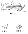
- Fig. 3 This preferred embodiment is shown in Fig. 3, like elements having the same numerals as in Fig. 1.
- the torch is indicated generally by the numeral 1 and comprising a concentric arrangement of tubular elements, the torch device similarly having an input section 1A and an output section 1B.
- Centrally located tubular element 2 is depicted supported axially as shown.
- Nebulizer tube 4 is sealed to flange 3 and has a feed inlet 3A for the nebulizer flow shown in more detail in Fig. 1.
- Tubular element 2 has a sample inlet port 7 and extends to a distance intermediate to the input and output sections and terminates substantially at 2A.
- Element 2 is surrounded by cover gas tube 32 which has an inlet port 33 through which a cover gas of argon is passed, tube 32 being sealed to tube 2.
- the tube 4 for the nebulizer flow surrounds the cover gas tube and has an inlet port 3A into which a nebulizer flow is introduced from a nebulizer not shown but which is illustrated in Fig. 1.
- the nebulizer tube element terminates at 4A as shown.
- Tube 11 concentrically surrounds nebulizer flow tube 4 and is used to provide auxiliary flow of plasma gas.
- the tube is sealed at the inlet section to tube 4 at 11A while outermost tube 12 is sealed to tube 11 at 12A.
- Tubes 11 and 12 have inlet ports 11B and 12B, respectively, for receiving plasma gas.
- the two tubes extend to the output section as in Fig. 1 and function in the same manner.
- Fig. 5 is a cross section of the torch shown in Fig. 2 taken along line 5-5 in which sample tube 2 is surrounded by cover gas tube 32 which in turn is surrounded by nebulizer flow tube 4 followed concentrically by tubes 11 and 12.
- Figs. 1-5 enable the analysis of reactive compounds such as trimethylgallium.
- reactive compounds such as trimethylgallium.
- examples of other compounds include WF6, In(CH3)3, SiH4 and PH3.
- the torch device of the invention is particularly applicable to analyzing trialkyl and dialkyl metal compounds which tend to react with water and oxyen.
- a torch device comprised of a hollow elongated cylindrical body having an output section cooperably associated with an inductively coupled plasma generating means and a mixing chamber located rearwardly of the output section.
- the method comprises feeding a sample of the reactive gas or vapor to said mixing chamber 10, separately feeding a nebulizer flow of plasma gas mixed with water vapor or an aerosol thereof into the same mixing chamber to effect mixing of the sample and the nebulizer flow, and immediately feeding the mixture surrounded by an annular sheath of plasma gas into and through the output section for thermal dissociation by a plasma flame generated in the output section prior to analysis by the mass spectrometer.
- the invention also provides a method for preparing a sample before the introduction of the sample into the system for analysis.
- the method comprises confining a liquid form of said sample in a bubbler device, bubbling a stream of carrier gas into the liquid sample and thereby entrain at least a portion of said sample into the stream of carrier gas, and passing the stream of carrier gas with the entrained sample to a vaporizer and from there under moderate pressure just above atmospheric pressure to a line that bifurcates to provide a branch line extending to and through a check valve and a bleed-off branch extending to and through a shut-off valve.
- a portion of the gas stream is adapted to pass through the bleed-off valve and the remainder of the gas stream to pass through the check valve.
- the bleed-off portion is passed to a gas line connected to a source of plasma gas adapted to flow to the ICP means, thereby delivering the sample thereto.
- the remainder of the sample and carrier gas is passed through the check valve to a scrubber containing a solvent for the sample, thereby separating the sample from the carrier gas, the separated carrier gas being then discharged from the scrubber.
- the scrubber solution is a Lewis base and vice versa.
- the method of the invention enables the analysis of reactive compounds, such as trimethylgallium, with optimum accuracy.
Abstract
Description
- This invention relates to a torch system and method for introducing a sample of gas or vapor, such as a reactive gas or vapor, into an inductively coupled plasma for the subsequent analysis of said sample by analytical means, such as a mass spectrometer, a spectroscope or similar analytical means.
- It is known to use an inductively coupled plasma torch for converting an elemental composition into ions for analysis by a mass spectrometer. The composition to be analyzed is dissolved in a solution which is introduced into the system by means of a nebulizer through which a controlled flow of argon is passed. Argon is fed to the inductively coupled plasma torch (ICP) at the output section thereof to provide and maintain a plasma flame similar to atomic emission spectroscopy.
- Reference is made to U.S. Patent No. 4,760,253 which issued on July 26, 1988, and which relates to the use of an inductively coupled plasma with a mass spectrometer adapted for the elemental analysis of a sample.
- This patent is directed to a mass spectrometer in which at least some of the ions formed from a sample introduced into an inductively coupled plasma (ICP) are caused to enter a sampling member comprised of a front surface adjacent to the plasma, a rear surface, and a hole connecting the front and rear surfaces through which at least some of the ions pass.
- The spectrometer described in the patent has a chamber in which a wall thereof comprises the rear surface of the sampling member. The pressure in the chamber is maintained substantially below atmospheric and at least some of the ions entering the chamber are caused to enter a mass analyzer. The improvement in the patent resides in providing the rear surface with a polish finish in order to reduce the intensity of background spectra which prevail in prior instruments and which limit the sensitivity of the instrument to certain elements.
- Other prior art patents include U.S. Patent Nos. 3,467,471; 4,551,609 and 4,688,935.
- U.S. Patent No. 3,467,471 relates to the production of a gas plasma and to the spectroscopic examination of the radiation emitted from the plasma from a sample, e.g., a phosphorus-containing sample, introduced into the plasma. The spectroscopic examination is used as a means for controlling manufacturing processes which require analysis of raw material or a product.
- U.S. Patent No. 4,551,609 is directed to a plasma burner or torch for emission spectrometry. The plasma burner described comprises an induction coil for generating a plasma, an outer jacket, an inner jacket coaxial with the outer jacket and a sleeve coaxially located inside the inner jacket. A capillary tube is located inside the sleeve and is oriented along the axis of symmetry. The torch or burner is provided with a cooling gas feed line, a plasma gas feed line, and an aerosol gas feed line. According to the patent, the rate of consumption of plasma gas as well as of the cooling gas is reduced, while the detection power of the device for such elements as boron, iron, magnesium, phosphorus and zinc is comparable to conventional plasma torches.
- U.S. Patent No. 4,688,935 is directed to the plasma spectroscopic analysis of organometallic compounds, particularly volatile, air or moisture sensitive or pyrophoric, liquid organometallic compounds. The method employed comprises inserting a sample of the compound into a flask referred to as an exponential dilution flask. Substantially the entire sample is allowed to vaporize and the vapor analyzed by plasma spectroscopy. Another method is disclosed in which the sample is decomposed by dropwise addition into frozen aqueous acid, diluting the decomposed sample with water and analyzing the diluted, decomposed sample by plasma spectroscopy.
- Nebulization of solutions is a convenient way for sample introduction into an inductively coupled plasma system. It is considered a major step forward in mass spectrometry. Water solutions of the sample to be analyzed are employed. Gas is passed through the nebulizer and entrains the sample as an aerosol which is subsequently introduced into the ICP torch.
- However, a disadvantage of this method is that it is not useful on samples which react with air or moisture, such as certain metallo-organic compounds. A case in point, is trimethylgallium, among others. If trimethylgallium is added to the solution, it tends to react, whereby the sample ultimately reaching the inductively coupled plasma section is not truly representative of the total trimethylgallium composition with respect to impurities, concentration, etc.
- It would therefore be desirable to provide a system and a method in which samples of reactive gases and vapors can be accurately analyzed without the samples losing their integrity before reaching the plasma section of the torch.
- It is thus an object of the invention to provide a torch system for introducing a gas or vapor, e.g., a reactive gas or vapor, into a plasma flame and effect thermal dissociation therein before the sample is introduced into a mass spectrometer for analysis.
- Another object is to provide a method for introducing a sample of reactive gas or vapor into a plasma flame while maintaining the integrity of the sample from a composition view point up to its introduction into the plasma flame.
- These and other objects will more clearly appear when taken in conjunction with the following disclosure, claims and the accompanying drawings.
-
- Fig. 1 is a schematic diagram of the torch illustrating one embodiment of the invention;
- Fig. 2 is a flow sheet illustrating one method of sample preparation;
- Fig. 3 is a schematic of another embodiment of a torch for carrying out the invention;
- Fig. 4 is a cross section of the torch taken along line 4-4 of Fig. 1; and
- Fig. 5 is a similar cross section taken along line 5-5 of Fig. 3.
- In its broad aspect, the invention resides in a torch device wherein the sample, for example, a reactive gas or vapor, is introduced into the torch system without having to pass through the nebulizer but which in the course of passing through the torch is mixed with the nebulizer solution in the form of an aerosol or vapor dispersed in a plasma gas just before it enters the inductively coupled plasma means (ICP). A plasma gas is defined as a gas which produces gas plasma when excited in a high frequency electric field.
- One embodiment of the invention resides in a torch device for use in preparing a sample of a reactive gas or vapor for analysis by a mass spectrometer or other type of analyzer cooperably associated with the torch device, such as an ICP-spectroscope. The torch device comprises a hollow elongated cylindrical body with an inductively coupled plasma means located at its output or forward section. The torch is provided with means for separately feeding a sample of the gas or vapor to be analyzed into a mixing chamber located rearward of the plasma means. The torch includes means for separately feeding a nebulizer flow of a plasma gas containing water or solvent vapor or an aerosol thereof into the mixing chamber to thereby mix with the sample, means being also provided for maintaining a sheath of plasma gas surrounding the sample mixture as it enters the plasma-forming means where it is thermally dissociated prior to introduction into the analyzer. Preferred examples of plasma gases include argon, nitrogen and helium which are inert.
- Another embodiment comprises a torch in the form of a hollow elongated cylindrical body having an input section at one end and an output section at its other end cooperably associated with an inductively coupled plasma means. The torch includes means for feeding a sample to be analyzed to the input section of the torch through a tubular element located in the torch body, e.g., a centrally located tubular element, and into a mixing chamber located forward of the input section; means for separately feeding an annular flow of a nebulized vapor comprising a plasma gas containing water or solvent vapor or aerosol thereof concentrically surrounding and separated from the sample flow and into the mixing chamber to thereby form a mixture thereof with the sample for immediate feeding to said inductively coupled plasma means; means for feeding into and from the input section a first annular sheath of plasma gas concentrically surrounding the sample and nebulizer flow and directly to the inductively coupled plasma means, and finally means for feeding into and from the input section a second annular sheath of plasma gas surrounding the first annular sheath as a coolant directly to the inductively coupled plasma means; whereby the integrity of the sample is maintained as it enters the inductively coupled plasma means for thermal dissociation therein prior to entering the mass spectrometer.
- Fig. 1 is illustrative of one embodiment of the torch device of the invention, the torch being identified generally by numeral 1 and comprising a concentric arrangement of quartz tubes, the torch device having an input section 1A and an
output section 1B. The arrangement comprises a substantially centrally locatedtubular element 2 supported axially which has a feed inlet 7 which communicates withtubular element 2 and through which the sample of gas or vapor to be analyzed is fed. - The
tubular element 2 extends to a distance intermediate to the input and output sections and terminates substantially at 2A.Element 2 is surrounded bytubular element 4 which is sealed to and extends fromflange 3 as shown to beyondend 2A ofelement 2 and terminates substantially at 4A short of inductively coupled plasma means 5 at the output section, the inductively coupled plasma means comprising water cooledcoils 6 which is activated by high frequency electrical means not shown. The forward portion oftubular element 4 is slightly constricted at 4B. -
Tubular element 4 is employed to provide a nebulizer flow to the output section and is isolated from the sample flow from the inlet end up to aninternal mixing chamber 10 located intermediate the input and output sections of the torch device to be discussed later. -
Tubular element 4 has aninlet port 3A which is coupled topneumatic nebulizer 8. The nebulizer has aninlet 9 for receiving a plasma gas, e.g., argon (Ar), which aspirates andentrains nebulizer solution 8A which is converted into a vapor or aerosol and caused to flow intoinlet 3A ofnebulizer flow tube 4. Excess solution is drained through drain means 9A. - The arrangement of the
sample tube 2 tonebulizer flow tube 4 is such as to provide aninternal mixing chamber 10 located intermediate the input and output sections of the torch. There the gas sample is mixed with the vapor or aerosol of the nebulizer flow and the mixture immediately caused to flow intochamber 5A of the inductively coupled plasma means where the sample is thermally dissociated. To assure plasma formation, additional flow of plasma gas is provided through concentrically arrangedquartz tubes Tubular element 11 which concentrically surroundselement 4 is used to provide auxiliary flow of plasma gas, such as argon (Ar). Starting at the inlet end,tube 11 is sealed totube 4 at 11A and has an inlet port 11B into which the argon or other plasma gas is passed from a gas reservoir not shown.Tube 11 extends to the output section of the torch as shown. The plasma gas enterschamber 5A of the inductive coupled plasma means where it is ionized by high frequency electric field flowing throughcoil 6 to provideplasma flame 5B. - In addition to the auxiliary flow of argon through
tubular element 11, an additional annular flow of plasma gas is provided as a coolant throughoutermost tube 12 which extends from the inlet section 1A to theoutput section 1B as shown. The tube is sealed at the inlet section totube 11 at 12A and has aninlet port 12B through which plasma gas coolant is fed, e.g., argon (Ar). - By using the system illustrated in the schematic of Fig. 1, the mixing of the reactive gas or vapor with the nebulizer gases or aerosol in
nebulizer 8 itself is avoided and hence the disadvantages of said premature mixing. Thus, the composition integrity of the reactive gas or vapor is retained until it is mixed with the nebulizer flow within the torch immediately beforechamber 5A where it is dissociated, for example, thermally dissociated. The ions formed in the plasma flame are caused to pass throughaperture 13 of sampling means 14 mounted on a water-cooled flange 15 and then into the analyzer for analysis, for example, a mass spectrometer. In this connection, reference is made to U.S. Patent No. 4,760,253. - Referring to the cross section of Fig. 1 taken along line 4-4 as shown in Fig. 4, the concentric arrangement of the tubular elements clearly appear with
sample tube 2 located at substantially the center which in turn is concentrically surrounded bynebulizer flow tube 4.Tube 4 is surrounded byauxiliary flow tube 11 which in turn is surrounded bytube 12 through which coolant plasma gas flows from the input end to the output end of the torch device. - One method for preparing the reactive gas sample or vapor is shown in the flow sheet of Fig. 2. A liquid of
trimethygallium 20 is placed in bubblingdevice 21 and a plasma gas (e.g., argon) fed vialine 22. The saturated argon is sent through a heat exchanger or vaporizer vialine 23 to which argon is also fed to insure that any droplets or aerosol is transformed to the vapor phase. Following vaporization, the reactive gas or vapor is passed alongline 24 to a "T"connection 24A from which a branch line extends to and throughcheck valve 28 and a bleed-off branch line extends to and through gas flow regulating means 25. The trimethylgallium passes throughcheck valve 28 and is maintained at about 1 psig (lbs/in² gage). The gas is caused to flow under positive pressure, for example, 0.5 psig to about 25 psig or higher. Part of the flow is passed through gas flow regulating means 25 to a "T"connection 26 and a plasma gas, e.g., argon (Ar) 27 added and caused to flow together with the trimethylgallium to the inductively coupled plasma means 5 (ICP) as shown. - The remaining reactive gas or vapor passes through
check valve 28 and is introduced into bubbler orscrubber 29 so that the gas is not conveyed to the atmosphere. The bubbler contains a solvent, in this case a Lewis base diamyl ether, for taking up trimethylgallium which is Lewis acid. The scrubbed plasma-forming gas is discharged throughline 30. - Where the sample being analyzed is a Lewis acid, the solution used as a scrubber is a Lewis base. Alternatively, where the sample is a Lewis base, the scrubbing solution would be a Lewis acid. The reaction product of a Lewis acid and a Lewis base is referred to as an adduct.
- Thus, the sample to be analyzed could be a Lewis base, such as trimethylarsine and phosphine.
- Examples of Lewis acids are boron trifluoride, trimethylborane, trimethylaluminum, and other metal alkyl compounds.
- Other examples of Lewis bases include diamyl ether, triakylphosphate,and tributylphosphate, among others. The Lewis bases should have a low vapor pressure.
- A preferred use of the nebulizer is to include an element as a reference standard in order to tune and calibrate the mass spectrometer. One standard which has been used is the element indium which is added to the nebulizer solution in the form of an indium standard solution purchased from Spex Industries. Other standards may be employed in accordance with conventional analytical procedures. Such standards may comprise salts of copper, nickel, cadmium, etc.
- When the reactive trimethylgallium gas is passed through
tube 2 of Fig. 1, clogging is apt to occur after a given period of time at itsexit end 2A. One way of inhibiting clogging is to surroundtube 2 by another tube through which a cover gas of argon or other plasma gas is passed, the cover gas tube terminating at approximately thesame distance 2A offeed tube 2. - This preferred embodiment is shown in Fig. 3, like elements having the same numerals as in Fig. 1. Thus, referring to Fig. 3, the torch is indicated generally by the numeral 1 and comprising a concentric arrangement of tubular elements, the torch device similarly having an input section 1A and an
output section 1B. Centrally locatedtubular element 2 is depicted supported axially as shown.Nebulizer tube 4 is sealed toflange 3 and has afeed inlet 3A for the nebulizer flow shown in more detail in Fig. 1. -
Tubular element 2 has a sample inlet port 7 and extends to a distance intermediate to the input and output sections and terminates substantially at 2A.Element 2 is surrounded bycover gas tube 32 which has aninlet port 33 through which a cover gas of argon is passed,tube 32 being sealed totube 2. - The
tube 4 for the nebulizer flow surrounds the cover gas tube and has aninlet port 3A into which a nebulizer flow is introduced from a nebulizer not shown but which is illustrated in Fig. 1. The nebulizer tube element terminates at 4A as shown. - The remaining elements are the same as in Fig. 1. Thus, to assure plasma formation, additional flow of plasma gas is provided through concentrially arranged
quartz tubes Tube 11 concentrically surroundsnebulizer flow tube 4 and is used to provide auxiliary flow of plasma gas. The tube is sealed at the inlet section totube 4 at 11A whileoutermost tube 12 is sealed totube 11 at 12A.Tubes inlet ports 11B and 12B, respectively, for receiving plasma gas. The two tubes extend to the output section as in Fig. 1 and function in the same manner. - Fig. 5 is a cross section of the torch shown in Fig. 2 taken along line 5-5 in which
sample tube 2 is surrounded bycover gas tube 32 which in turn is surrounded bynebulizer flow tube 4 followed concentrically bytubes - The embodiments shown in Figs. 1-5 enable the analysis of reactive compounds such as trimethylgallium. Examples of other compounds include WF₆, In(CH₃)₃, SiH₄ and PH₃.
- The torch device of the invention is particularly applicable to analyzing trialkyl and dialkyl metal compounds which tend to react with water and oxyen.
- Another embodiment of the invention resides in a method for preparing a sample of a reactive gas or vapor for analysis by a mass spectrometer in which a torch device is employed comprised of a hollow elongated cylindrical body having an output section cooperably associated with an inductively coupled plasma generating means and a mixing chamber located rearwardly of the output section.
- The method comprises feeding a sample of the reactive gas or vapor to said mixing
chamber 10, separately feeding a nebulizer flow of plasma gas mixed with water vapor or an aerosol thereof into the same mixing chamber to effect mixing of the sample and the nebulizer flow, and immediately feeding the mixture surrounded by an annular sheath of plasma gas into and through the output section for thermal dissociation by a plasma flame generated in the output section prior to analysis by the mass spectrometer. - The invention also provides a method for preparing a sample before the introduction of the sample into the system for analysis. The method comprises confining a liquid form of said sample in a bubbler device, bubbling a stream of carrier gas into the liquid sample and thereby entrain at least a portion of said sample into the stream of carrier gas, and passing the stream of carrier gas with the entrained sample to a vaporizer and from there under moderate pressure just above atmospheric pressure to a line that bifurcates to provide a branch line extending to and through a check valve and a bleed-off branch extending to and through a shut-off valve. A portion of the gas stream is adapted to pass through the bleed-off valve and the remainder of the gas stream to pass through the check valve.
- The bleed-off portion is passed to a gas line connected to a source of plasma gas adapted to flow to the ICP means, thereby delivering the sample thereto. The remainder of the sample and carrier gas is passed through the check valve to a scrubber containing a solvent for the sample, thereby separating the sample from the carrier gas, the separated carrier gas being then discharged from the scrubber.
- As stated herein, when the sample is a Lewis acid, the scrubber solution is a Lewis base and vice versa.
- The method of the invention enables the analysis of reactive compounds, such as trimethylgallium, with optimum accuracy.
- The following advantages are achieved with the invention:
- (1) It allows a wet plasma to be used which is the normal condition for which the inductively coupled plasma-mass spectrometer (ICP-MS) is designed;
- (2) It increases the sensitivity of the ICP-MS for analyzing reactive samples, such as metal alkyls;
- (3) It provides a safe way of handling reactive liquids before introduction to ICP-MS.
- (4) It allows a standard to be introduced into the nebulizer flow which does not affect the sample in order to tune and calibrate the mass spectrometer for optimal performance levels.
- Although the present invention has been described in conjunction with the preferred embodiment, it is to be understood that modifications and variations may be resorted to without departing from the spirit and scope of the invention, as those skilled in the art will readily understand. Such modifications and variations are considered to be within the purview and scope of the invention and appended claims.
Claims (14)
means (2) for separately feeding a sample of said reactive gas or vapor into a mixing chamber (10) located rearward of said plasma generating means,
means (4) for separately feeding a nebulizer flow of a plasma gas and including water or solvent vapour or aerosol thereof into said mixing chamber (10) to thereby mix with said sample, and
means (11) for maintaining a first sheath of plasma gas concentrically about said sample mixture as it enters the plasma generating means for dissociation therein by a plasma flame including means (12) for maintaining a second sheath of plasma gas around said first sheath as a coolant prior to introduction of ions formed by dissociation into said analyzer.
said nebulizer flow means (4) and said tubular sample means (2) extending to a mixing chamber (10) where the nebulizer flow mixes with the sample flow before entering the plasma generating means.
means (8) for feeding a sample of reactive gas or vapor to be analyzed to the input section of said torch and through a tubular element (2) located in said torch body and into a mixing chamber (10) located forward of said input section,
means (4) for separately feeding an annular flow of a nebulized vapor comprising a plasma gas and including water or solvent vapor or aerosol thereof concentrically surrounding and separated from said sample flow and into said mixing chamber (10) to thereby form a mixture thereof with the sample for immediate feeding to said inductively coupled plasma means,
means for feeding into and from said input section (1A) a first annular sheath of plasma gas concentrically surrounding said sample and nebulizer flow and directly to said inductively coupled plasma means, and
means for feeding into and from said input section a second annular sheath of plasma gas as a coolant surrounding said first annular sheath directly to said inductively coupled plasma generating means,
whereby the integrity of said sample is maintained as it enters said inductively coupled plasma means for dissociation therein prior to entering the analyzer.
said device comprising a cylindrical longitudinal torch body having an output section (1B) and an input section (1A) and characterized by a plurality of concentrically arranged tubular members (2, 4, 11, 12) defining a plurality of annular passages therebetween for passing gas or vapor therethrough, said torch body terminating into a nozzle section (5) at said output section at which a plasma flame is generated, said torch body comprising:-
a first centrally located tubular member (2) with its end extending to a position intermediate to said input and output sections for receiving therein a sample of reactive gas or vapor to be analyzed,
a second tubular member (4) concentrically surrounding said first tubular member with its end extending beyond the end of said first tubular member and which defines a first chamber (10) forward of said first tubular member,
said second tubular member also defining an annular passage for receiving a nebulizing gas flow of a plasma gas and including water or solvent vapor or aerosol thereof for mixing with the reactive gas or vapor in said first chamber forward of said first tubular member,
a third tubular member (11) concentrically surrounding said second tubular member with its end extending to approximately the end of said second tubular member and defining an annular passage therebetween for receiving plasma gas therethrough, and
a fourth tubular member (12) concentrically surrounding said third member and defining an annular passage for receiving a plasma gas therein, said fourth tubular member extending beyond the end of said third tubular member and defining a second chamber (5A) forward of said third tubular member,
said second chamber including said nozzle section in which a plasma flame is generated,
whereby reactive gas or vapor fed through said first tubular member mixes with the nebulizing flow of gas in an atmosphere of plasma gas in said first chamber and the mixture immediately thereafter dissociated by a plasma flame initiated in the nozzle section of the second chamber of said torch body.
providing a torch device comprised of a hollow elongated cylindrical body having an output section (1A) with an inductively coupled plasma generating means (5, 6) surrounding said section,
said torch having a mixing chamber (10) disposed rearwardly of said output section and in communication therewith,
feeding a sample of said reactive gas or vapor to said mixing chamber,
separately feeding a nebulizer flow of a plasma gas mixed with water or solvent vapor or an aerosol thereof into said mixing chamber to effect mixing of said sample and said nebulizer flow, and
immediately feeding said mixture surrounded by an annular sheath of plasma-forming gas through said output section for dissociation by a plasma flame generated in said section prior to introduction of the dissociated sample into the analyzer.
confining a liquid form of said sample in a bubbler device (21),
bubbling a stream of carrier gas into said liquid sample and thereby entraining at least a portion of said sample into said stream of carrier gas,
causing said stream of carrier gas with the entrained sample to flow to a line (24) that bifurcates to provide a branch line extending to a scrubber (29) and a bleed-off branch line extending to and through a gas regulating means (25),
whereby a portion of the gas stream with the entrained sample is adapted to pass through said bleed-off line and the remainder of said gas stream adapted to pass to said scrubber,
passing said bleed-off portion to a gas line connected to a source of plasma gas (27) adapted to flow to said ICP means (5), thereby delivering the sample thereto,
causing the remainder of said sample and carrier gas to pass to said scrubber containing a solvent for said sample, thereby separating said sample substantially from said carrier gas,
and discharging said separated carrier gas from said scrubber.
such that when the sample is a Lewis acid, the solvent is a Lewis base and when the sample is a Lewis base, the solvent is a Lewis acid.
confining a liquid form of said sample in a bubbler device (21),
said sample being selected from the group consisting of a Lewis acid or a Lewis base,
bubbling a steam of carrier gas into said liquid sample and thereby entraining at least a portion of said sample into said stream of carrier gas,
passing said stream of carrier gas with the entrained sample to a vaporizer and from there under moderate pressure just above atmospheric to a line (24) that bifurcates to provide a branch line extending to a scrubber (29) and a bleed-off branch line extending to and through gas flow regulating means (25),
whereby a portion of the gas stream with the entrained sample is adapted to pass through said bleed-off line and the remainder of said gas stream adapted to pass to said scrubber,
passing said bleed-off portion to a gas line connected to a source of plasma gas adapted to flow to said IPC means (5), thereby delivering the sample thereto,
causing the remainder of said sample and carrier gas to pass to a scrubber (29) containing a solvent for said sample, thereby separating said sample substantially from said carrier gas,
said solvent being selected from the group consisting of a Lewis base or a Lewis acid, such that when the sample is a Lewis acid, the solvent is a Lewis base and when the sample is a Lewis base, the solvent is a Lewis acid,
and discharging said separated carrier gas from said scrubber.
Applications Claiming Priority (2)
| Application Number | Priority Date | Filing Date | Title |
|---|---|---|---|
| US242798 | 1988-09-09 | ||
| US07/242,798 US4926021A (en) | 1988-09-09 | 1988-09-09 | Reactive gas sample introduction system for an inductively coupled plasma mass spectrometer |
Publications (3)
| Publication Number | Publication Date |
|---|---|
| EP0358212A2 true EP0358212A2 (en) | 1990-03-14 |
| EP0358212A3 EP0358212A3 (en) | 1991-05-08 |
| EP0358212B1 EP0358212B1 (en) | 1995-04-19 |
Family
ID=22916228
Family Applications (1)
| Application Number | Title | Priority Date | Filing Date |
|---|---|---|---|
| EP89116530A Expired - Lifetime EP0358212B1 (en) | 1988-09-09 | 1989-09-07 | Reactive gas sample introduction system for an inductively coupled plasma torch |
Country Status (4)
| Country | Link |
|---|---|
| US (1) | US4926021A (en) |
| EP (1) | EP0358212B1 (en) |
| JP (2) | JP2949123B2 (en) |
| DE (1) | DE68922256T2 (en) |
Cited By (11)
| Publication number | Priority date | Publication date | Assignee | Title |
|---|---|---|---|---|
| EP0771019A1 (en) * | 1995-10-27 | 1997-05-02 | Hitachi, Ltd. | Method and apparatus for mass analysis of solution sample |
| US5663560A (en) * | 1993-09-20 | 1997-09-02 | Hitachi, Ltd. | Method and apparatus for mass analysis of solution sample |
| WO1998054935A1 (en) * | 1997-05-30 | 1998-12-03 | Centre National De La Recherche Scientifique | Inductive plasma torch with reagent injector |
| FR2773299A1 (en) * | 1997-12-29 | 1999-07-02 | Air Liquide | Plasma torch with adjustable injector for gas analysis |
| EP0930810A1 (en) * | 1997-12-29 | 1999-07-21 | L'air Liquide, Societe Anonyme Pour L'etude Et L'exploitation Des Procedes Georges Claude | Plasma torch with adjustable distributor and gas analysis system using such a torch |
| GB2410830A (en) * | 2004-02-06 | 2005-08-10 | Micromass Ltd | Ion source for a mass spectrometer |
| US7265362B2 (en) | 2004-02-06 | 2007-09-04 | Micromass Uk Limited | Mass spectrometer |
| US7294841B2 (en) | 2004-02-06 | 2007-11-13 | Micromass Uk Limited | Mass spectrometer |
| EP1855833A2 (en) * | 2005-03-11 | 2007-11-21 | PerkinElmer, Inc. | Plasmas and methods of using them |
| CN106304602A (en) * | 2016-09-26 | 2017-01-04 | 吉林大学 | A kind of microwave coupling plasma resonant |
| CN110603441A (en) * | 2017-05-12 | 2019-12-20 | 胜高股份有限公司 | Atomizing chamber, sample atomizing and introducing device, analyzer, and method for analyzing components in sample |
Families Citing this family (27)
| Publication number | Priority date | Publication date | Assignee | Title |
|---|---|---|---|---|
| US5026464A (en) * | 1988-08-31 | 1991-06-25 | Agency Of Industrial Science And Technology | Method and apparatus for decomposing halogenated organic compound |
| US5187344A (en) * | 1988-11-10 | 1993-02-16 | Agency Of Industrial Science And Technology | Apparatus for decomposing halogenated organic compound |
| US5233156A (en) * | 1991-08-28 | 1993-08-03 | Cetac Technologies Inc. | High solids content sample torches and method of use |
| US5272308A (en) * | 1991-12-27 | 1993-12-21 | Cetac Technologies Inc. | Direct injection micro nebulizer and enclosed filter solvent removal sample introduction system, and method of use |
| US5212365A (en) * | 1991-12-27 | 1993-05-18 | Cetac Technologies, Inc. | Direct injection micro nebulizer system and method of use |
| JP2852838B2 (en) * | 1992-09-10 | 1999-02-03 | セイコーインスツルメンツ株式会社 | Inductively coupled plasma mass spectrometer |
| GB9316742D0 (en) * | 1993-08-12 | 1993-09-29 | Univ Waterloo | Imtroduction of samples do inductively coupled plasma |
| US5404219A (en) * | 1994-01-04 | 1995-04-04 | Cetac Technologies Inc. | System for enhancing detection of sample components in plasma based sample analysis systems, and method of use |
| US5663476A (en) * | 1994-04-29 | 1997-09-02 | Motorola, Inc. | Apparatus and method for decomposition of chemical compounds by increasing residence time of a chemical compound in a reaction chamber |
| US5811631A (en) * | 1994-04-29 | 1998-09-22 | Motorola, Inc. | Apparatus and method for decomposition of chemical compounds using a self-supporting member |
| RU95106478A (en) * | 1994-04-29 | 1997-01-20 | Моторола | Arrangement and method for degradation of chemical compounds |
| JP3786724B2 (en) * | 1994-08-11 | 2006-06-14 | エスアイアイ・ナノテクノロジー株式会社 | Inductively coupled plasma analyzer and its sample introduction device |
| US6107634A (en) * | 1998-04-30 | 2000-08-22 | Eaton Corporation | Decaborane vaporizer |
| US6002097A (en) * | 1998-09-01 | 1999-12-14 | Transgenomic, Inc. | System and method for producing nebulized sample analyte containing solution for introduction to sample analysis systems |
| US20060124588A1 (en) * | 1999-01-05 | 2006-06-15 | Berg & Berg Enterprises, Llc | System and method for reducing metal oxides with hydrogen radicals |
| US6420275B1 (en) | 1999-08-30 | 2002-07-16 | Micron Technology, Inc. | System and method for analyzing a semiconductor surface |
| US7002144B1 (en) * | 1999-08-30 | 2006-02-21 | Micron Technology Inc. | Transfer line for measurement systems |
| US20030030010A1 (en) * | 2001-08-07 | 2003-02-13 | Perel Alexander S. | Decaborane vaporizer having improved vapor flow |
| JP2003194723A (en) * | 2001-12-27 | 2003-07-09 | Rikogaku Shinkokai | Plasma torch |
| US20040002166A1 (en) * | 2002-06-27 | 2004-01-01 | Wiederin Daniel R. | Remote analysis using aerosol sample transport |
| US6949741B2 (en) | 2003-04-04 | 2005-09-27 | Jeol Usa, Inc. | Atmospheric pressure ion source |
| US7429714B2 (en) * | 2003-06-20 | 2008-09-30 | Ronal Systems Corporation | Modular ICP torch assembly |
| JP2006038729A (en) * | 2004-07-29 | 2006-02-09 | National Institute Of Advanced Industrial & Technology | Inductively coupled plasma torch |
| JP5965743B2 (en) * | 2012-06-27 | 2016-08-10 | 株式会社日立ハイテクサイエンス | ICP device, spectroscopic analyzer, and mass spectrometer |
| JP5973969B2 (en) * | 2013-07-31 | 2016-08-23 | 国立大学法人徳島大学 | Inline densitometer and concentration detection method |
| CN106990158B (en) * | 2017-04-07 | 2020-02-07 | 鲁汶仪器有限公司(比利时) | Contamination detection system and method |
| CN110108779A (en) * | 2019-06-13 | 2019-08-09 | 西安奕斯伟硅片技术有限公司 | The method that quantitative detection is carried out to fluent material with ICP-MS |
Citations (4)
| Publication number | Priority date | Publication date | Assignee | Title |
|---|---|---|---|---|
| GB2122342A (en) * | 1982-06-22 | 1984-01-11 | Imperial College | Apparatus for liquid analysis |
| EP0132300A2 (en) * | 1983-06-24 | 1985-01-30 | Morton Thiokol, Inc. | Plasma spectroscopic analysis of organometallic compound |
| EP0231131A2 (en) * | 1986-01-31 | 1987-08-05 | Vg Instruments Group Limited | Inductively coupled plasma mass spectrometer |
| JPH01161132A (en) * | 1987-12-16 | 1989-06-23 | Shimadzu Corp | Icp light emission analyzing device |
Family Cites Families (6)
| Publication number | Priority date | Publication date | Assignee | Title |
|---|---|---|---|---|
| US29304A (en) * | 1860-07-24 | Compensating lever-sprincr | ||
| GB1033392A (en) * | 1962-06-20 | 1966-06-22 | Atomic Energy Authority Uk | Improvements in or relating to induction coupled plasma generators |
| JPS5945900U (en) * | 1982-09-17 | 1984-03-27 | 住友電気工業株式会社 | Torch for high frequency induced plasma |
| DE3310742A1 (en) * | 1983-03-24 | 1984-09-27 | Siemens AG, 1000 Berlin und 8000 München | PLASMA BURNER FOR ICP EMISSION SPECTROMETRY |
| US4665296A (en) * | 1984-04-28 | 1987-05-12 | Neturen Co., Ltd. | Method of and apparatus for igniting a high-frequency torch to create a high-temperature plasma of high purity |
| US4739147A (en) * | 1987-01-30 | 1988-04-19 | The Dow Chemical Company | Pre-aligned demountable plasma torch |
-
1988
- 1988-09-09 US US07/242,798 patent/US4926021A/en not_active Expired - Lifetime
-
1989
- 1989-09-07 EP EP89116530A patent/EP0358212B1/en not_active Expired - Lifetime
- 1989-09-07 DE DE68922256T patent/DE68922256T2/en not_active Expired - Fee Related
- 1989-09-11 JP JP1235504A patent/JP2949123B2/en not_active Expired - Fee Related
-
1998
- 1998-09-24 JP JP10269624A patent/JP3141232B2/en not_active Expired - Fee Related
Patent Citations (4)
| Publication number | Priority date | Publication date | Assignee | Title |
|---|---|---|---|---|
| GB2122342A (en) * | 1982-06-22 | 1984-01-11 | Imperial College | Apparatus for liquid analysis |
| EP0132300A2 (en) * | 1983-06-24 | 1985-01-30 | Morton Thiokol, Inc. | Plasma spectroscopic analysis of organometallic compound |
| EP0231131A2 (en) * | 1986-01-31 | 1987-08-05 | Vg Instruments Group Limited | Inductively coupled plasma mass spectrometer |
| JPH01161132A (en) * | 1987-12-16 | 1989-06-23 | Shimadzu Corp | Icp light emission analyzing device |
Non-Patent Citations (3)
| Title |
|---|
| ANALYTICAL CHEMISTRY. vol. 56, no. 7, June 1984, COLUMBUS US pages 875 - 888; R F BROWNER: "SAMPLE INTRODUCTION TECHNIQUES FOR ATOMIC SPECTROSCOPY" * |
| ANALYTICAL CHEMISTRY. vol. 58, no. 8, July 1986, COLUMBUS US pages 1734 - 1738; I BERTENYI, R M BARNES: "ANALYSIS OF TRIMETHYLGALLIUM WITH INDUCTIVELY COUPLED PLASMA SPECTROMETRY" * |
| PATENT ABSTRACTS OF JAPAN vol. 13, no. 428 (P-936)(3776) 25 September 1989, & JP-A-01 161132 (SHIMADZU) 23 June 1989, * |
Cited By (18)
| Publication number | Priority date | Publication date | Assignee | Title |
|---|---|---|---|---|
| US5663560A (en) * | 1993-09-20 | 1997-09-02 | Hitachi, Ltd. | Method and apparatus for mass analysis of solution sample |
| EP0771019A1 (en) * | 1995-10-27 | 1997-05-02 | Hitachi, Ltd. | Method and apparatus for mass analysis of solution sample |
| WO1998054935A1 (en) * | 1997-05-30 | 1998-12-03 | Centre National De La Recherche Scientifique | Inductive plasma torch with reagent injector |
| FR2764163A1 (en) * | 1997-05-30 | 1998-12-04 | Centre Nat Rech Scient | INDUCTIVE PLASMA TORCH WITH REAGENT INJECTOR |
| FR2773299A1 (en) * | 1997-12-29 | 1999-07-02 | Air Liquide | Plasma torch with adjustable injector for gas analysis |
| EP0930810A1 (en) * | 1997-12-29 | 1999-07-21 | L'air Liquide, Societe Anonyme Pour L'etude Et L'exploitation Des Procedes Georges Claude | Plasma torch with adjustable distributor and gas analysis system using such a torch |
| US6236012B1 (en) | 1997-12-29 | 2001-05-22 | L'air Liquide, Societe Anonyme Pour L'etude Et L'exploitation Des Procedes Georges Claude | Plasma torch with an adjustable injector and gas analyzer using such a torch |
| US7265362B2 (en) | 2004-02-06 | 2007-09-04 | Micromass Uk Limited | Mass spectrometer |
| GB2410830A (en) * | 2004-02-06 | 2005-08-10 | Micromass Ltd | Ion source for a mass spectrometer |
| US7294841B2 (en) | 2004-02-06 | 2007-11-13 | Micromass Uk Limited | Mass spectrometer |
| GB2410830B (en) * | 2004-02-06 | 2008-06-04 | Micromass Ltd | Mass spectrometer |
| EP1855833A2 (en) * | 2005-03-11 | 2007-11-21 | PerkinElmer, Inc. | Plasmas and methods of using them |
| EP1855833A4 (en) * | 2005-03-11 | 2014-03-05 | Perkinelmer Inc | Plasmas and methods of using them |
| CN106304602A (en) * | 2016-09-26 | 2017-01-04 | 吉林大学 | A kind of microwave coupling plasma resonant |
| CN106304602B (en) * | 2016-09-26 | 2018-07-20 | 吉林大学 | A kind of microwave coupling plasma resonant |
| CN110603441A (en) * | 2017-05-12 | 2019-12-20 | 胜高股份有限公司 | Atomizing chamber, sample atomizing and introducing device, analyzer, and method for analyzing components in sample |
| CN110603441B (en) * | 2017-05-12 | 2022-06-03 | 胜高股份有限公司 | Atomizing chamber, sample atomizing and introducing device, analysis device and method for analyzing components in sample |
| US11648574B2 (en) | 2017-05-12 | 2023-05-16 | Sumco Corporation | Spray chamber, sample atomization and introduction device, analysis device, and method of analyzing component in sample |
Also Published As
| Publication number | Publication date |
|---|---|
| JPH0362443A (en) | 1991-03-18 |
| EP0358212A3 (en) | 1991-05-08 |
| US4926021A (en) | 1990-05-15 |
| JP2949123B2 (en) | 1999-09-13 |
| JP3141232B2 (en) | 2001-03-05 |
| DE68922256D1 (en) | 1995-06-01 |
| DE68922256T2 (en) | 1995-10-26 |
| EP0358212B1 (en) | 1995-04-19 |
| JPH11183388A (en) | 1999-07-09 |
Similar Documents
| Publication | Publication Date | Title |
|---|---|---|
| EP0358212B1 (en) | Reactive gas sample introduction system for an inductively coupled plasma torch | |
| US8896830B2 (en) | Devices and systems including a boost device | |
| Savage et al. | Development and characterization of a miniature inductively coupled plasma source for atomic emission spectrometry | |
| US4833294A (en) | Inductively coupled helium plasma torch | |
| US8822948B1 (en) | Method and apparatus for control of a plasma for spectrometry | |
| Schickling et al. | Optimization of electrochemical hydride generation coupled to microwave-induced plasma atomic emission spectrometry for the determination of arsenic and its use for the analysis of biological tissue samples | |
| CA2608528C (en) | Boost devices and methods of using them | |
| Pisonero et al. | High efficiency aerosol dispersion cell for laser ablation-ICP-MS | |
| Michlewicz et al. | Determination of aqueous chloride by direct nebulization into a helium microwave induced plasma | |
| Donati et al. | Tungsten coil electrothermal matrix decomposition and sample vaporization to determine P and Si in biodiesel by inductively coupled plasma mass spectrometry | |
| US5081397A (en) | Atmospheric pressure capacitively coupled plasma atomizer for atomic absorption and source for atomic emission spectroscopy | |
| Hauptkorn et al. | Determination of trace impurities in high-purity quartz by electrothermal vaporization inductively coupled plasma mass spectrometry using the slurry sampling technique | |
| US6236012B1 (en) | Plasma torch with an adjustable injector and gas analyzer using such a torch | |
| US5939648A (en) | System and method of introducing a sample for analytical atomic spectrometry allowing concomitant analysis of mercury | |
| EP0510127B1 (en) | Method and apparatus for analytical sample preparation | |
| Camuna-Aguilar et al. | A comparative study of three microwave induced plasma sources for atomic emission spectrometry—I. Excitation of mercury and its determination after on-line continuous cold vapour generation | |
| JPH06102181A (en) | Analysis method for hydrogen sulfide | |
| CA3208773A1 (en) | Inductively coupled plasma torches and methods and systems including same | |
| Fengzhou et al. | A compact, versatile, integrated nebulizer-hydride generator system for simultaneous determination of volatile elemental hydrides and other elements by ICP-AES | |
| JP3804798B2 (en) | Evaporation supply device for liquid organometallic compounds | |
| Duan et al. | Electrothermal vaporization for sample introduction in microwave-induced plasma atomic absorption spectrometry | |
| Reeves et al. | Molecular Emission Spectra in the Radio-frequency-excited Inductively Coupled Argon Plasma | |
| Hood et al. | Determination of sulfur-and phosphorus-containing compounds using metastable transfer emission spectrometry | |
| CA2185832A1 (en) | Analyzer using plasma and analysis method using plasma, interface used for the same and sample introducing component used for the same | |
| Duan et al. | Study on microwave induced plasma atomic absorption spectrometry (MIP-AAS) for the determination of calcium in axial viewing mode |
Legal Events
| Date | Code | Title | Description |
|---|---|---|---|
| PUAI | Public reference made under article 153(3) epc to a published international application that has entered the european phase |
Free format text: ORIGINAL CODE: 0009012 |
|
| AK | Designated contracting states |
Kind code of ref document: A2 Designated state(s): DE FR GB NL |
|
| PUAL | Search report despatched |
Free format text: ORIGINAL CODE: 0009013 |
|
| AK | Designated contracting states |
Kind code of ref document: A3 Designated state(s): DE FR GB NL |
|
| 17P | Request for examination filed |
Effective date: 19911107 |
|
| 17Q | First examination report despatched |
Effective date: 19930730 |
|
| GRAA | (expected) grant |
Free format text: ORIGINAL CODE: 0009210 |
|
| RAP1 | Party data changed (applicant data changed or rights of an application transferred) |
Owner name: VG INSTRUMENTS GROUP LIMITED Owner name: MATHESON GAS PRODUCTS, INC. |
|
| AK | Designated contracting states |
Kind code of ref document: B1 Designated state(s): DE FR GB NL |
|
| REF | Corresponds to: |
Ref document number: 68922256 Country of ref document: DE Date of ref document: 19950601 |
|
| ET | Fr: translation filed | ||
| PLBE | No opposition filed within time limit |
Free format text: ORIGINAL CODE: 0009261 |
|
| STAA | Information on the status of an ep patent application or granted ep patent |
Free format text: STATUS: NO OPPOSITION FILED WITHIN TIME LIMIT |
|
| 26N | No opposition filed | ||
| REG | Reference to a national code |
Ref country code: GB Ref legal event code: IF02 |
|
| PGFP | Annual fee paid to national office [announced via postgrant information from national office to epo] |
Ref country code: NL Payment date: 20020827 Year of fee payment: 14 |
|
| PGFP | Annual fee paid to national office [announced via postgrant information from national office to epo] |
Ref country code: GB Payment date: 20020904 Year of fee payment: 14 |
|
| PGFP | Annual fee paid to national office [announced via postgrant information from national office to epo] |
Ref country code: DE Payment date: 20020907 Year of fee payment: 14 |
|
| PGFP | Annual fee paid to national office [announced via postgrant information from national office to epo] |
Ref country code: FR Payment date: 20020909 Year of fee payment: 14 |
|
| PG25 | Lapsed in a contracting state [announced via postgrant information from national office to epo] |
Ref country code: GB Free format text: LAPSE BECAUSE OF NON-PAYMENT OF DUE FEES Effective date: 20030907 |
|
| PG25 | Lapsed in a contracting state [announced via postgrant information from national office to epo] |
Ref country code: NL Free format text: LAPSE BECAUSE OF NON-PAYMENT OF DUE FEES Effective date: 20040401 Ref country code: DE Free format text: LAPSE BECAUSE OF NON-PAYMENT OF DUE FEES Effective date: 20040401 |
|
| GBPC | Gb: european patent ceased through non-payment of renewal fee |
Effective date: 20030907 |
|
| PG25 | Lapsed in a contracting state [announced via postgrant information from national office to epo] |
Ref country code: FR Free format text: LAPSE BECAUSE OF NON-PAYMENT OF DUE FEES Effective date: 20040528 |
|
| NLV4 | Nl: lapsed or anulled due to non-payment of the annual fee |
Effective date: 20040401 |
|
| REG | Reference to a national code |
Ref country code: FR Ref legal event code: ST |