EP0357870B1 - Unitary rotational speed sensor - Google Patents
Unitary rotational speed sensor Download PDFInfo
- Publication number
- EP0357870B1 EP0357870B1 EP19890107995 EP89107995A EP0357870B1 EP 0357870 B1 EP0357870 B1 EP 0357870B1 EP 19890107995 EP19890107995 EP 19890107995 EP 89107995 A EP89107995 A EP 89107995A EP 0357870 B1 EP0357870 B1 EP 0357870B1
- Authority
- EP
- European Patent Office
- Prior art keywords
- rotor
- rotational speed
- stator
- speed sensor
- coil
- Prior art date
- Legal status (The legal status is an assumption and is not a legal conclusion. Google has not performed a legal analysis and makes no representation as to the accuracy of the status listed.)
- Expired - Lifetime
Links
Images


Classifications
-
- G—PHYSICS
- G01—MEASURING; TESTING
- G01P—MEASURING LINEAR OR ANGULAR SPEED, ACCELERATION, DECELERATION, OR SHOCK; INDICATING PRESENCE, ABSENCE, OR DIRECTION, OF MOVEMENT
- G01P3/00—Measuring linear or angular speed; Measuring differences of linear or angular speeds
- G01P3/42—Devices characterised by the use of electric or magnetic means
- G01P3/44—Devices characterised by the use of electric or magnetic means for measuring angular speed
- G01P3/48—Devices characterised by the use of electric or magnetic means for measuring angular speed by measuring frequency of generated current or voltage
- G01P3/481—Devices characterised by the use of electric or magnetic means for measuring angular speed by measuring frequency of generated current or voltage of pulse signals
- G01P3/488—Devices characterised by the use of electric or magnetic means for measuring angular speed by measuring frequency of generated current or voltage of pulse signals delivered by variable reluctance detectors
-
- F—MECHANICAL ENGINEERING; LIGHTING; HEATING; WEAPONS; BLASTING
- F16—ENGINEERING ELEMENTS AND UNITS; GENERAL MEASURES FOR PRODUCING AND MAINTAINING EFFECTIVE FUNCTIONING OF MACHINES OR INSTALLATIONS; THERMAL INSULATION IN GENERAL
- F16C—SHAFTS; FLEXIBLE SHAFTS; ELEMENTS OR CRANKSHAFT MECHANISMS; ROTARY BODIES OTHER THAN GEARING ELEMENTS; BEARINGS
- F16C33/00—Parts of bearings; Special methods for making bearings or parts thereof
- F16C33/72—Sealings
- F16C33/723—Shaft end sealing means, e.g. cup-shaped caps or covers
-
- G—PHYSICS
- G01—MEASURING; TESTING
- G01P—MEASURING LINEAR OR ANGULAR SPEED, ACCELERATION, DECELERATION, OR SHOCK; INDICATING PRESENCE, ABSENCE, OR DIRECTION, OF MOVEMENT
- G01P3/00—Measuring linear or angular speed; Measuring differences of linear or angular speeds
- G01P3/42—Devices characterised by the use of electric or magnetic means
- G01P3/44—Devices characterised by the use of electric or magnetic means for measuring angular speed
- G01P3/443—Devices characterised by the use of electric or magnetic means for measuring angular speed mounted in bearings
-
- G—PHYSICS
- G01—MEASURING; TESTING
- G01P—MEASURING LINEAR OR ANGULAR SPEED, ACCELERATION, DECELERATION, OR SHOCK; INDICATING PRESENCE, ABSENCE, OR DIRECTION, OF MOVEMENT
- G01P3/00—Measuring linear or angular speed; Measuring differences of linear or angular speeds
- G01P3/42—Devices characterised by the use of electric or magnetic means
- G01P3/44—Devices characterised by the use of electric or magnetic means for measuring angular speed
- G01P3/48—Devices characterised by the use of electric or magnetic means for measuring angular speed by measuring frequency of generated current or voltage
- G01P3/481—Devices characterised by the use of electric or magnetic means for measuring angular speed by measuring frequency of generated current or voltage of pulse signals
- G01P3/487—Devices characterised by the use of electric or magnetic means for measuring angular speed by measuring frequency of generated current or voltage of pulse signals delivered by rotating magnets
-
- F—MECHANICAL ENGINEERING; LIGHTING; HEATING; WEAPONS; BLASTING
- F16—ENGINEERING ELEMENTS AND UNITS; GENERAL MEASURES FOR PRODUCING AND MAINTAINING EFFECTIVE FUNCTIONING OF MACHINES OR INSTALLATIONS; THERMAL INSULATION IN GENERAL
- F16C—SHAFTS; FLEXIBLE SHAFTS; ELEMENTS OR CRANKSHAFT MECHANISMS; ROTARY BODIES OTHER THAN GEARING ELEMENTS; BEARINGS
- F16C41/00—Other accessories, e.g. devices integrated in the bearing not relating to the bearing function as such
- F16C41/007—Encoders, e.g. parts with a plurality of alternating magnetic poles
Definitions
- This invention relates generally to rotational speed sensors, and more particularly to compact, unitary rotational speed sensors.
- Rotational speed sensors are used in many control and indicating systems.
- One frequently used type employs the variable reluctance principle.
- Common problems in such sensors in the prior art include keeping the device compact so that it can fit into small spaces, maintaining close control over rotor-stator spacing, and providing sufficient output signal in terms of both signal amplitude and number of pulses per revolution.
- Prior art devices known to the inventors include those disclosed in U.S. Patent Nos. 2,462,761 to 3,480,812 to Hershberger; 3,596,122 to Stewart; 3,604,966 to Liggett; 3,649,859 to Watt; 4,027,753 to Lantz; and 4,110,647 to Eslinger et al.
- the Hershberger device shows a nesting arrangement of rotor, magnet, coil and stator elements.
- Watt discloses a reluctance-type rotational speed sensor utilizing radially extending teeth on both stator and rotor.
- the Lantz device comprises a sealed system. None of the above-mentioned devices, however, combine the various teachings of the present invention to obtain a significantly more compact design that is capable of greater output levels, and versatile enough for use in many environments.
- a rotational speed sensor for detecting the rotational speed of a wheel hub is known from the US Patent No. 3,683,219.
- the rotational speed sensor is mounted over an axel in abutment on the stator and is secured against rotation by a nose in a coil body which engages in a longitudinal groove.
- the stator is constructed as annular member with U-shaped cross-section. The coil body with the coil winding is inserted into the U-shaped cross-section. An inner leg portion of the stator body carries a radial friction bearing on which the rotor is supported.
- the present invention provides a rotational speed sensor having a more compact structure, which is easier to produce and which can generate a high output signal for its size.
- the present invention provides a rotational speed sensor comprising a stator having circumferentially spaced teeth means formed thereon; a coil of wire disposed coaxial with said stator; a magnet disposed coaxial with said stator; a rotor arranged for rotation about a rotational axis and having first and second axially spaced radially extending surfaces, including circumferentially spaced teeth means; said teeth means of said stator being arranged in physical opposition and in close proximity to said teeth means of said rotor, whereby an electrical current is induced in said coil upon rotation of said rotor;
- the stator includes two coaxial, axially spaced stator elements, each stator element having opposed inner and outer radially extending surfaces, each inner surface having said teeth means formed thereon; said coil of wire is disposed between said stator elements; said magnet is disposed between said stator elements; said teeth means of said rotor are formed on said first and second surfaces of said rotor; and said rotor, said coil and said magnet nest co
- the present rotational speed sensor improves upon prior art speed sensors by utilizing an axially compact design to obtain accurate measurements in a variety of environments.
- the flat, generally circular shape allows the sensor to measure the rotational speed of either a rotating shaft or a rotating bore.
- the sensor is designed to minimize the effects of eccentricities and unwanted relative movement between sensor components. For example, both radial runout and axial runout have minimal effect on the output of the sensor.
- the particular design of the magnetic circuit used by this sensor enables it to generate a high output signal for its size.
- the present speed sensor includes a rotor and a stator, each having teeth defining slots, in conjunction with an annular magnet to increase and decrease magnetic flux in the magnetic circuit, enabling measurement of angular speed in accordance with the increase and decrease of the flux.
- the changes in flux generated by the rotor system induce alternating current in a coil of wire in a well known manner to produce signals representative of angular speed.
- annular magnet circumscribes a sensing coil having a unitary rotor nested within it, and is disposed between two elements which comprise the stator.
- a magnet is disposed between two halves which comprise a rotor, the entire assembly nesting within a sensing coil and being disposed between the two stator elements.
- Either embodiment may be used, with minor modifications, in environments where a rotating shaft turns within a stationary bore, or where a rotating bore turns about a stationary shaft.
- a preferably annular rotational speed sensor constructed according to the teachings of the present invention is indicated generally at 10 in Figure 1.
- the sensor is mounted in stationary bore 12, and is driven by rotating shaft 14.
- Electrical leads 16 come from an internal sensing coil.
- Figure 2 is an exploded view of the basic components employed in one exemplary embodiment of speed sensor 10. As shown in Figure 2, the components of this first embodiment telescope into sensor retainer 18 from the left. Edge 20 is rolled over to cooperate with lip 22 in retaining the sensor components within retainer 18.
- the double-lipped design shown in Figure 2 is merely one example of suitable retaining means that could be used with the present embodiment. A variety of other retaining means can be used, including adhesives.
- Annular stator elements 24 and 26 provide a magnetic path for the aforementioned magnetic flux extending from inner edge 28 to outer edge 30.
- Circumferentially spaced, radially disposed teeth 32 and slots are formed on the inner faces of stator elements 24 and 26, and act in conjunction with corresponding teeth 34 and slots formed in rotor 36 to provide the means for sensing rotational speed, as discussed in greater detail below.
- Annular magnet 38 axially poled, provides magnetic flux for sensor 10.
- a sensing coil, shown encapsulated at 40 consists of a simple multi-turn winding wound so that its axis is coincident with the linear axis of the assembled sensor. Lead wires 16 extend from the two ends of coil 40 to carry alternating current representing rotational speed signals to an external signal processing unit (not shown).
- rotor 36 is rotationally driven by shaft 14. Both rotor 36 and stator elements 24, 26 have an equal number of radially disposed teeth and slots.
- the radial length of the rotor teeth 34 is preferably slightly less than the length of the stator teeth 32, and the rotor teeth 34 are positioned relative to the stator teeth 32 in such a way that the rotor teeth 34 lie within the length of the stator teeth 32.
- Rotor 36 nests within coil 40, and the rotor-coil combination nests coaxially within magnet 38. This assembly in turn is located coaxially with and between stator elements 24 and 26.
- Figure 3 is a sectional view of the sensor shown in Figure 1 taken along lines III-III and looking in the direction of the arrows. In this view, the nesting relationship of rotor 36, coil 40 and magnet 38 is shown.
- Stator elements 24 and 26 are relatively thin members, made of, for example, 22 gauge steel. In the design shown, the stator elements 24, 26 are backed by a layer of a non-magnetic material such as injection-molded plastic, as indicated at 44. Stator elements 24, 26 are bonded to retainer 18 by appropriate means, for example by adhesively bonding backing layers 44 to retainer 18. This particular cross section of the stator elements 24 and 26 shows a slot at 31 in each stator element. Teeth and slots in the stator elements may be formed by a variety of methods including stamping or etching. In the final construction, slots 31 are preferably filled with backing material 44.
- stator elements 24 and 26 must be positioned relative to each other so that teeth and slots are in axial alignment. This may be accomplished by a variety of methods, including projections on the stator elements which match with indentations on coil 40, magnet 38, or optional spacer 42.
- Coil 40 is shown encapsulated by bobbin 46. Connections to the ends of coil 40 are made by lead wires 16, which exit through strain relief 48 on bobbin 46. Stator element 24 and backing material 44 are provided with an opening to allow strain relief 48 to pass.
- Rotor 36 is slightly thinner than the space between the stator elements 24 and 26 to provide running clearance, and the outer diameter of rotor 36 is less than the inner diameter of coil 40 to provide sufficient clearance to account for eccentricity and dimensional tolerances.
- Rotor 36 may be a one-piece element, or may comprise two halves oriented with outwardly-facing teeth to operate in the same manner as the one-piece rotor.
- the rotor is preferably encapsulated in plastic or other suitable material (for example, backing material 44) such that slots 33 are filled flush with teeth 34, thus forming a unitary element regardless of one- or two-piece design.
- Rim 50 shown on the inside diameter of rotor 36, retains elastomeric ring 52.
- Ring 52 serves four functions. First, it provides a friction drive between shaft 14 and rim 50 of rotor 36. Second, it provides vibration isolation of the rotor relative to its driving member. Third, the area of contact between stator elements 24, 26 and ring 52 provides a running seal to keep contaminants out of the relatively moving parts of sensor 10. Fourth, compression of the ring at the stator element sealing surface provides a centering force for rotor 36, tending to keep the rotor from contacting the stator elements 24, 26. For added insurance against rotor-stator contact, rotor rims may be included, as described below with respect to Figure 5.
- Friction drive of the rotor via ring 52 is the preferred drive means for the rotational speed sensor; other drive means, however, including tangs or keys engaging slots on the rotating shaft, could also be used, with or without a seal.
- a toroidal magnetic flux path 53 is thus established around coil 40 and proceeds axially from one face of magnet 38 to one adjacent stator element, radially through the stator element, axially into rotor 36 and out of rotor 36 into the other stator element, and finally radially through this second stator element and back into magnet 38.
- the rotor and stator teeth 34 and 32 move into and out of juxtaposition to alternately decrease and increase the magnetic reluctance of the magnetic path.
- the change in reluctance increases and decreases the magnetic flux in the magnetic path.
- This change in flux generates a voltage in coil 40 in accordance with known principles.
- the output voltage on leads 16 will be an alternating voltage with an amplitude proportional to the speed of rotation, and a frequency equal to the speed of rotation times the number of teeth in 360°.
- the Figure 3 embodiment requires retainer 18 to be non-magnetic to avoid shunting of magnetic flux. Furthermore, if bore 12 is ferromagnetic, a spacer 42 must be included to avoid shunting by the bore.
- FIG 4 shows the sensor cross section of Figure 3, but with stator elements 24 and 26 composed of a composite material rather than a metal plate backed by a non-metal backing material.
- Stator elements 24 and 26 may, for example, be molded from a plastic or nylon having iron powder dispersed to a density such that its permeability is sufficient to provide an adequate magnetic path.
- the advantages of this method of construction include better dimensional control of components and lower cost due to simpler processing.
- Slots 31 and 33 in stator elements 24, 26 and rotor 36 may be filled with nonmagnetic material as before to prevent damage due to rubbing.
- FIG. 5 shows a second embodiment of a rotational speed sensor.
- rotor 136 is shown split into two halves, sandwiching magnet 138.
- Magnet 138 further has relatively smaller inner and outer diameters, approximately equal now to those of the rotor halves 135 and 137 so that the rotor-magnet assembly nests within coil 140 and between stator elements 124 and 126.
- Coil 140 may be adhesively or otherwise fastened to stator elements 124, 126. So long as the thickness of magnet 138 is appreciably greater than the combined air gaps shown at 154 and 156, the operating point on the demagnetization curve of magnet 138 will be high enough to provide an adequate change in flux to produce a sufficient voltage from coil 140.
- Magnet 138 therefore, may be as thin as is operationally practical. This embodiment has the advantages of reducing space requirements, decreasing the cost of magnet 138 and eliminating the shunting effect of a steel bore (such as 12) in close proximity to magnet 38 as in the first embodiment.
- Rotor 136 is constructed to maintain a minimum rotor-stator clearance.
- the two ferromagnetic rotor halves 135 and 137 are indexed and placed in an injection molding cavity with magnet 138 between them.
- Rotor rims 158 and 160 are then molded around rotor halves 135 and 137 and magnet 138.
- the molding cavity is constructed so that air gaps 154 and 156 are created. These gaps are on the order of 0.005 inches.
- Rotor rims 158 and 160 are shown abutting stator element 124 with running clearance from stator element 126. Rotor rims 158 and 160 may run in contact with either stator element or float between the stator elements, but are always in preventive contact with rotor 136 (i.e., contact rotor 136 in such a manner that rotor teeth 134 never contact stator teeth 132). Although shown as rims, rotor rims 158 and 160 may be any suitable spacer means for maintaining rotor-stator spacing. A nearly true sine wave output from coil 140 is achieved with no anomalies so long as a few thousandths of an inch clearance is maintained between rotor and stator teeth 134 and 132, a goal achieved by rims 158 and 160.
- rotor rims 158 and 160 act as bearing surfaces running against stator elements 124 and 126, the composition of rims 158 and 160 must be compatible with the stator material to minimize wear.
- the stator material For example, if steel stator elements are used, nylon or nylon with a low-friction additive would be satisfactory. If iron-filled composite is used for the stator elements (as shown in Figure 5), the stator matrix would preferably be polyethersulphone working against nylon rims.
- sensor 110 may be filled with grease or oil, with lubrication lands put in the rim area facing the stator elements.
- a single rotor rim e.g., 158 or 160 may be used instead of two.
- the elastomeric ring 152 which forms the seal for this second embodiment, performs essentially the same functions as elastomeric ring 52 from the first embodiment, but is located differently on the second embodiment sensor. As shown in Figure 5, ring 152 extends along both the extension of rim 160 and stator elements 124 and 126, but does so without the cavity formed between the two stator elements. As such, elastomeric ring 152 acts as a low-friction axial seal instead of as a radial seal.
- Figure 7 shows a sensor 210 mounted on a stationary shaft 214 with rotor 236 being driven by a rotating bore 212.
- the arrangement shown in Figure 7 functions in essentially the same manner as the arrangement of Figure 5, but with the radial positioning of elastomeric ring 152, rotor 136, and coil 140 reversed.
- Figure 7 shows shaft 214 being used to close the flux path. It must, therefore, have a composition capable of providing a magnetic flux path, for example steel.
- the stator elements may be fastened to the coil using adhesive.
- FIG. 8 shows a sensor 110 such as that shown in Figure 5 nested within a differential case adjusting ring 162.
- Axle housing member 164 is stationary, and connected to a vehicle through the suspension system.
- Differential case 166 carries a ring gear 168 and is rotationally driven by a pinion.
- Differential case 166 also carries differential gears 170 and 172, which turn axle 174 through splines 176.
- Tapered roller bearing 178 and a similar bearing (not shown) on the other side of axle 174 allow differential case 166 to rotate freely. Adjusting ring 162 and a similar ring on the other end of axle 174 retain and position differential case 166 through the tapered roller bearings 178 in the axle housing 164. Adjusting ring 162 is externally threaded as seen at 180, and it screws into the stationary axle housing 164. By means of the two adjusting rings 162, ring gear 168 is properly postitioned along the axis of axle 174 relative to the drive pinion. Adjusting rings 162 have castellations which are used to lock the position of adjusting ring 162 with a cotter key. A flanged portion 182 on differential case 166 extends out between adjusting ring 162 and axle 174.
- Speed sensor 110 and adjusting ring 162 are sized for a light press fit of sensor 110 into adjusting ring 162.
- An adhesive may also be used for a more secure fit.
- Elastomeric ring 152 slides over the outside of flange 182 on differential case 166.
- Flange 182 is long enough to protect sensor 110 from being damaged when axle 174 is put into the axle assembly.
- Friction drive of the rotor via the elastomeric ring is the preferred drive means for the rotational speed sensor. Friction drive makes assembly easy, and it eliminates alignment problems associated with locking the rotor to the driving element (flange 182 in the Figure 8 embodiment). Tang drive is possible, but requires extremely close tolerances to avoid backlash, which could give erroneous speed signals.
- FIG 9 shows a partial sectional view through the center of a modified speed sensor mounted as in the Figure 8 embodiment, but incorporating a combined friction and tang drive.
- Rotor rim 160 includes tangs 163 and 165, which protrude through slots 151 and 153 in elastomeric ring 152. Slots 151 and 153 are axially located in the center of ring 152 so as to maintain the integrity of ring 152.
- Flange 182 has slots 185 and 187 formed in it to accept tangs 163 and 165.
- Slots 185 and 187 may be formed wider than the tangs for ease of assembly.
- Tang drive in the Figure 9 arrangement is a backup drive means to the preferred friction drive. Normal rotation is accomplished by the frictional force between elastomeric ring 152 and flange 182. When the torque requirement exceeds the frictional capabilities, however, tangs 163 and 165 are engaged via slots 185 and 187 to drive the rotor.
- Sensor 110 thus measures the speed of rotation of the differential case. If the vehicle is not turning a corner, both differential case 166 and the wheels (not shown) are rotating at the same angular speed. If the vehicle is turning, the outside wheel turns faster than the inside wheel, and the differential case 166 turns at the average speed of the two wheels on that axle (assuming only two wheels on the axle).
- An antilock braking system can utilize the differential case speed to control the brakes on that axle.
- Figure 10 shows the speed sensor 210 of Figure 7 applied to measure the speed of rotation of a non-driven wheel, as determined by measuring the rotation speed of wheel hub 284.
- Elastomeric ring 252 contacts hubcap 212 along its inside surface 286.
- Hubcap 212 is piloted on wheel hub 284 via flange portion 288 to assure that hubcap 212 is concentric with wheel spindle 214. As the wheel spindle 214 and hub 284 turn, hubcap 212 drives speed sensor 210.
- Speed sensor 210 functions in essentially the same manner as the previous sensor is described. As shown in Figure 10, however, the outer structural design of speed sensor 210 is modified to fit the particular exemplary environment.
- Stator elements 224 and 226 are metal plates molded into backing layers 244 in a fashion similar to that described with respect to Figure 3.
- Channel 290 is formed in the backing material behind both stator elements 224 and 226 to provide a conduit for leads coming from coil 240 to connector 292, and therefore to external processing circuitry.
- a sensor hub 294 formed from the backing material of the internal stator slidably engages counterbore 296 of spindle 214.
- An O-ring 298 seals counterbore 296.
- Hubcap 212 seals the hub end and retains the bearing lubricant.
- Hubcap 212 is preferably an injection molding of a clear plastic to allow easy visual inspection of lubricant level.
- Channels 285 are provided in hubcap 212 to allow lubricant to flow from the spindle side of sensor 210 to the hubcap side.
- Figure 11 shows another application for a rotational speed sensor like that of Figure 5.
- Sensor 310 is installed in the output end of transmission case 311. In this installation, sensor 310 measures the speed of transmission output shaft 314 and also acts as the output shaft oil seal. Sensor 310 is pressed into bore 312 on case 311. Lead wires 316 from sensor 310 conduct the alternating voltage signal from coil 340 to connector 392, and thus to external processing circuity (not shown).
- Sensor 310 measures the speed of shaft 314 via universal joint yoke 382, which slides over shaft 314.
- Shaft 314 and yoke 382 are radially engaged by splines 376 and axially held by a bolt and washer (not shown).
- a dirt seal 353 is also provided.
- This elastomeric seal 353 is bonded to retainer 318.
- the side face 320 of retainer 318 is much wider than the corresponding side face 20 of retainer 18 shown in Figure 2, since dirt seal 353 must be supported close to the inside diameter surface of sensor 310.
- Dirt seal 353 prevents dirt and water from getting to elastomeric ring 352 and beyond.
- the annular ring gap 355 formed between seals 352 and 353 may be packed with grease to trap any dirt which might get past dirt seal 353.
- stator teeth have been defined as having greater radial length than the rotor teeth to reduce radial runout. Having rotor teeth longer than stator teeth achieves a similar result.
- wire leads connecting the sensing coil to processing circuitry is exemplary; any suitable communication means may be used.
- the disclosed combination of tang drive and friction drive is additionally feasible for various applications of the speed sensor.
Description
- This invention relates generally to rotational speed sensors, and more particularly to compact, unitary rotational speed sensors.
- Rotational speed sensors are used in many control and indicating systems. One frequently used type employs the variable reluctance principle. Common problems in such sensors in the prior art include keeping the device compact so that it can fit into small spaces, maintaining close control over rotor-stator spacing, and providing sufficient output signal in terms of both signal amplitude and number of pulses per revolution.
- Prior art devices known to the inventors include those disclosed in U.S. Patent Nos. 2,462,761 to 3,480,812 to Hershberger; 3,596,122 to Stewart; 3,604,966 to Liggett; 3,649,859 to Watt; 4,027,753 to Lantz; and 4,110,647 to Eslinger et al. In particular, the Hershberger device shows a nesting arrangement of rotor, magnet, coil and stator elements. Watt discloses a reluctance-type rotational speed sensor utilizing radially extending teeth on both stator and rotor. The Lantz device comprises a sealed system. None of the above-mentioned devices, however, combine the various teachings of the present invention to obtain a significantly more compact design that is capable of greater output levels, and versatile enough for use in many environments.
- Furthermore, a rotational speed sensor for detecting the rotational speed of a wheel hub is known from the US Patent No. 3,683,219. The rotational speed sensor is mounted over an axel in abutment on the stator and is secured against rotation by a nose in a coil body which engages in a longitudinal groove. The stator is constructed as annular member with U-shaped cross-section. The coil body with the coil winding is inserted into the U-shaped cross-section. An inner leg portion of the stator body carries a radial friction bearing on which the rotor is supported.
- The present invention provides a rotational speed sensor having a more compact structure, which is easier to produce and which can generate a high output signal for its size.
- More specifically, the present invention provides a rotational speed sensor comprising a stator having circumferentially spaced teeth means formed thereon; a coil of wire disposed coaxial with said stator; a magnet disposed coaxial with said stator; a rotor arranged for rotation about a rotational axis and having first and second axially spaced radially extending surfaces, including circumferentially spaced teeth means; said teeth means of said stator being arranged in physical opposition and in close proximity to said teeth means of said rotor, whereby an electrical current is induced in said coil upon rotation of said rotor; according to the invention the stator includes two coaxial, axially spaced stator elements, each stator element having opposed inner and outer radially extending surfaces, each inner surface having said teeth means formed thereon; said coil of wire is disposed between said stator elements; said magnet is disposed between said stator elements; said teeth means of said rotor are formed on said first and second surfaces of said rotor; and said rotor, said coil and said magnet nest coaxially between said stator elements.
- The present rotational speed sensor improves upon prior art speed sensors by utilizing an axially compact design to obtain accurate measurements in a variety of environments. The flat, generally circular shape allows the sensor to measure the rotational speed of either a rotating shaft or a rotating bore. The sensor is designed to minimize the effects of eccentricities and unwanted relative movement between sensor components. For example, both radial runout and axial runout have minimal effect on the output of the sensor. Furthermore, the particular design of the magnetic circuit used by this sensor enables it to generate a high output signal for its size.
- The present speed sensor includes a rotor and a stator, each having teeth defining slots, in conjunction with an annular magnet to increase and decrease magnetic flux in the magnetic circuit, enabling measurement of angular speed in accordance with the increase and decrease of the flux. The changes in flux generated by the rotor system induce alternating current in a coil of wire in a well known manner to produce signals representative of angular speed.
- Two embodiments of the invention are disclosed. In the first embodiment, an annular magnet circumscribes a sensing coil having a unitary rotor nested within it, and is disposed between two elements which comprise the stator. In a second embodiment, a magnet is disposed between two halves which comprise a rotor, the entire assembly nesting within a sensing coil and being disposed between the two stator elements. Either embodiment may be used, with minor modifications, in environments where a rotating shaft turns within a stationary bore, or where a rotating bore turns about a stationary shaft.
-
- Figure 1 is a perspective view of one embodiment of the present speed sensor, showing the sensor mounted in a stationary bore and driven by a rotating shaft;
- Figure 2 is an exploded view of the components of the sensor of Figure 1;
- Figure 3 is a sectional view taken along the lines III-III in Figure 1;
- Figure 4 is a sectional view of the sensor shown in Figure 3 but having an alternate stator construction;
- Figure 5 is a sectional view of the sensor according to a second disclosed embodiment;
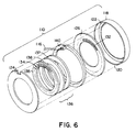
- Figure 6 is an exploded view of the components of the sensor shown in Figure 5;
- Figure 7 shows the subject sensor in an alternate configuration suitable for measuring the speed of a rotating bore;
- Figure 8 is a view of the sensor shown in Figure 5 mounted in a differential case adjusting ring to measure differential case speed;
- Figure 9 is a sectional view of a modification of the arrangement shown in Figure 8;
- Figure 10 is a view of the sensor mounted on a wheel spindle within a hubcap for measuring wheel speed; and
- Figure 11 is a view of the sensor shown in Figure 5 installed in the output end of a transmission case.
- A preferably annular rotational speed sensor constructed according to the teachings of the present invention is indicated generally at 10 in Figure 1. The sensor is mounted in
stationary bore 12, and is driven by rotatingshaft 14. Electrical leads 16 come from an internal sensing coil. - Figure 2 is an exploded view of the basic components employed in one exemplary embodiment of
speed sensor 10. As shown in Figure 2, the components of this first embodiment telescope intosensor retainer 18 from the left. Edge 20 is rolled over to cooperate withlip 22 in retaining the sensor components withinretainer 18. The double-lipped design shown in Figure 2 is merely one example of suitable retaining means that could be used with the present embodiment. A variety of other retaining means can be used, including adhesives.Annular stator elements outer edge 30. Circumferentially spaced, radially disposedteeth 32 and slots are formed on the inner faces ofstator elements corresponding teeth 34 and slots formed inrotor 36 to provide the means for sensing rotational speed, as discussed in greater detail below.Annular magnet 38, axially poled, provides magnetic flux forsensor 10. A sensing coil, shown encapsulated at 40, consists of a simple multi-turn winding wound so that its axis is coincident with the linear axis of the assembled sensor.Lead wires 16 extend from the two ends ofcoil 40 to carry alternating current representing rotational speed signals to an external signal processing unit (not shown). - In this first exemplary embodiment,
rotor 36 is rotationally driven byshaft 14. Bothrotor 36 andstator elements rotor teeth 34 is preferably slightly less than the length of thestator teeth 32, and therotor teeth 34 are positioned relative to thestator teeth 32 in such a way that therotor teeth 34 lie within the length of thestator teeth 32. By this design, signal losses due to magnetic shunting and radial runout are reduced.Rotor 36 nests withincoil 40, and the rotor-coil combination nests coaxially withinmagnet 38. This assembly in turn is located coaxially with and betweenstator elements - Figure 3 is a sectional view of the sensor shown in Figure 1 taken along lines III-III and looking in the direction of the arrows. In this view, the nesting relationship of
rotor 36,coil 40 andmagnet 38 is shown. -
Stator elements stator elements Stator elements retainer 18 by appropriate means, for example by adhesively bonding backing layers 44 toretainer 18. This particular cross section of thestator elements backing material 44. Filling the slots presents a smooth continuous surface on the inner face of each stator element, so that if therotor 36 rubs against it no damage will occur. Thestator elements coil 40,magnet 38, oroptional spacer 42. -
Coil 40 is shown encapsulated bybobbin 46. Connections to the ends ofcoil 40 are made bylead wires 16, which exit throughstrain relief 48 onbobbin 46.Stator element 24 andbacking material 44 are provided with an opening to allowstrain relief 48 to pass. -
Rotor 36 is slightly thinner than the space between thestator elements rotor 36 is less than the inner diameter ofcoil 40 to provide sufficient clearance to account for eccentricity and dimensional tolerances. - Several techniques can be used to fabricate
rotor 36 including sintering powdered iron.Rotor 36 may be a one-piece element, or may comprise two halves oriented with outwardly-facing teeth to operate in the same manner as the one-piece rotor. The rotor is preferably encapsulated in plastic or other suitable material (for example, backing material 44) such that slots 33 are filled flush withteeth 34, thus forming a unitary element regardless of one- or two-piece design. -
Rim 50, shown on the inside diameter ofrotor 36, retainselastomeric ring 52.Ring 52 serves four functions. First, it provides a friction drive betweenshaft 14 and rim 50 ofrotor 36. Second, it provides vibration isolation of the rotor relative to its driving member. Third, the area of contact betweenstator elements ring 52 provides a running seal to keep contaminants out of the relatively moving parts ofsensor 10. Fourth, compression of the ring at the stator element sealing surface provides a centering force forrotor 36, tending to keep the rotor from contacting thestator elements - Friction drive of the rotor via
ring 52 is the preferred drive means for the rotational speed sensor; other drive means, however, including tangs or keys engaging slots on the rotating shaft, could also be used, with or without a seal. - A toroidal
magnetic flux path 53 is thus established aroundcoil 40 and proceeds axially from one face ofmagnet 38 to one adjacent stator element, radially through the stator element, axially intorotor 36 and out ofrotor 36 into the other stator element, and finally radially through this second stator element and back intomagnet 38. Asrotor 36 rotates, the rotor andstator teeth coil 40 in accordance with known principles. The output voltage on leads 16 will be an alternating voltage with an amplitude proportional to the speed of rotation, and a frequency equal to the speed of rotation times the number of teeth in 360°. - The Figure 3 embodiment requires
retainer 18 to be non-magnetic to avoid shunting of magnetic flux. Furthermore, ifbore 12 is ferromagnetic, aspacer 42 must be included to avoid shunting by the bore. - Figure 4 shows the sensor cross section of Figure 3, but with
stator elements Stator elements stator elements rotor 36 may be filled with nonmagnetic material as before to prevent damage due to rubbing. - Figure 5 shows a second embodiment of a rotational speed sensor. With reference to both Figure 5 and Figure 6,
rotor 136 is shown split into two halves, sandwichingmagnet 138.Magnet 138 further has relatively smaller inner and outer diameters, approximately equal now to those of the rotor halves 135 and 137 so that the rotor-magnet assembly nests withincoil 140 and betweenstator elements Coil 140 may be adhesively or otherwise fastened tostator elements magnet 138 is appreciably greater than the combined air gaps shown at 154 and 156, the operating point on the demagnetization curve ofmagnet 138 will be high enough to provide an adequate change in flux to produce a sufficient voltage fromcoil 140.Magnet 138, therefore, may be as thin as is operationally practical. This embodiment has the advantages of reducing space requirements, decreasing the cost ofmagnet 138 and eliminating the shunting effect of a steel bore (such as 12) in close proximity tomagnet 38 as in the first embodiment. -
Rotor 136 is constructed to maintain a minimum rotor-stator clearance. In an exemplary construction, the two ferromagnetic rotor halves 135 and 137 are indexed and placed in an injection molding cavity withmagnet 138 between them. Rotor rims 158 and 160 are then molded aroundrotor halves magnet 138. The molding cavity is constructed so thatair gaps - By relocating
magnet 138 betweenrotor halves magnet 138 across one air gap, radially through the adjacent stator element, then axially throughretainer 118, down radially through the other stator element, and back tomagnet 138. - Rotor rims 158 and 160 are shown abutting
stator element 124 with running clearance fromstator element 126. Rotor rims 158 and 160 may run in contact with either stator element or float between the stator elements, but are always in preventive contact with rotor 136 (i.e.,contact rotor 136 in such a manner thatrotor teeth 134 never contact stator teeth 132). Although shown as rims, rotor rims 158 and 160 may be any suitable spacer means for maintaining rotor-stator spacing. A nearly true sine wave output fromcoil 140 is achieved with no anomalies so long as a few thousandths of an inch clearance is maintained between rotor andstator teeth rims - Since rotor rims 158 and 160 act as bearing surfaces running against
stator elements rims sensor 110 may be filled with grease or oil, with lubrication lands put in the rim area facing the stator elements. Depending upon wear characteristics, a single rotor rim (e.g., 158 or 160) may be used instead of two. - The
elastomeric ring 152, which forms the seal for this second embodiment, performs essentially the same functions aselastomeric ring 52 from the first embodiment, but is located differently on the second embodiment sensor. As shown in Figure 5,ring 152 extends along both the extension ofrim 160 andstator elements elastomeric ring 152 acts as a low-friction axial seal instead of as a radial seal. - All of the configurations discussed thus far are designed for speed sensing of a rotating shaft within a stationary bore. The present speed sensor may be modified to also satisfy requirements where the shaft is stationary and the bore rotates. Figure 7 shows a
sensor 210 mounted on astationary shaft 214 withrotor 236 being driven by arotating bore 212. The arrangement shown in Figure 7 functions in essentially the same manner as the arrangement of Figure 5, but with the radial positioning ofelastomeric ring 152,rotor 136, andcoil 140 reversed. Figure 7 showsshaft 214 being used to close the flux path. It must, therefore, have a composition capable of providing a magnetic flux path, for example steel. As in the Figure 5 configuration, the stator elements may be fastened to the coil using adhesive. - One application for a flat, compact speed sensor such as the present invention is for measurement of wheel speed in a driving axle of a vehicle. Figure 8 shows a
sensor 110 such as that shown in Figure 5 nested within a differentialcase adjusting ring 162.Axle housing member 164 is stationary, and connected to a vehicle through the suspension system.Differential case 166 carries aring gear 168 and is rotationally driven by a pinion.Differential case 166 also carriesdifferential gears axle 174 throughsplines 176. -
Tapered roller bearing 178 and a similar bearing (not shown) on the other side ofaxle 174 allowdifferential case 166 to rotate freely. Adjustingring 162 and a similar ring on the other end ofaxle 174 retain and positiondifferential case 166 through the taperedroller bearings 178 in theaxle housing 164. Adjustingring 162 is externally threaded as seen at 180, and it screws into thestationary axle housing 164. By means of the two adjustingrings 162,ring gear 168 is properly postitioned along the axis ofaxle 174 relative to the drive pinion. Adjusting rings 162 have castellations which are used to lock the position of adjustingring 162 with a cotter key. Aflanged portion 182 ondifferential case 166 extends out between adjustingring 162 andaxle 174. -
Speed sensor 110 and adjustingring 162 are sized for a light press fit ofsensor 110 into adjustingring 162. An adhesive may also be used for a more secure fit.Elastomeric ring 152 slides over the outside offlange 182 ondifferential case 166.Flange 182 is long enough to protectsensor 110 from being damaged whenaxle 174 is put into the axle assembly. - As mentioned previously, friction drive of the rotor via the elastomeric ring is the preferred drive means for the rotational speed sensor. Friction drive makes assembly easy, and it eliminates alignment problems associated with locking the rotor to the driving element (
flange 182 in the Figure 8 embodiment). Tang drive is possible, but requires extremely close tolerances to avoid backlash, which could give erroneous speed signals. - Tang drive would be required, however, in certain circumstances where high drive torque might overcome the frictional force of a friction drive means. In such a circumstance, a combination of friction drive and tang drive is preferred. Figure 9 shows a partial sectional view through the center of a modified speed sensor mounted as in the Figure 8 embodiment, but incorporating a combined friction and tang drive.
Rotor rim 160 includestangs slots elastomeric ring 152.Slots ring 152 so as to maintain the integrity ofring 152.Flange 182 hasslots tangs Slots elastomeric ring 152 andflange 182. When the torque requirement exceeds the frictional capabilities, however, tangs 163 and 165 are engaged viaslots -
Sensor 110 thus measures the speed of rotation of the differential case. If the vehicle is not turning a corner, bothdifferential case 166 and the wheels (not shown) are rotating at the same angular speed. If the vehicle is turning, the outside wheel turns faster than the inside wheel, and thedifferential case 166 turns at the average speed of the two wheels on that axle (assuming only two wheels on the axle). An antilock braking system can utilize the differential case speed to control the brakes on that axle. - The same basic arrangement shown in Figure 8 can also be used for traction control, which requires measuring the speed of both wheels on an axle. For this application, a
sensor 110 is installed in both adjustingrings 162 used to positiondifferential case 166.Flange 182, however, is removed and the sensor dimensions are modified so thatsensor 110 is driven directly byaxle 174. Knowing the speed of each wheel, a brake can be applied to balance the wheel speeds. - Figure 10 shows the
speed sensor 210 of Figure 7 applied to measure the speed of rotation of a non-driven wheel, as determined by measuring the rotation speed ofwheel hub 284.Elastomeric ring 252 contacts hubcap 212 along itsinside surface 286.Hubcap 212 is piloted onwheel hub 284 viaflange portion 288 to assure thathubcap 212 is concentric withwheel spindle 214. As thewheel spindle 214 andhub 284 turn,hubcap 212 drivesspeed sensor 210. -
Speed sensor 210 functions in essentially the same manner as the previous sensor is described. As shown in Figure 10, however, the outer structural design ofspeed sensor 210 is modified to fit the particular exemplary environment.Stator elements backing layers 244 in a fashion similar to that described with respect to Figure 3.Channel 290 is formed in the backing material behind bothstator elements connector 292, and therefore to external processing circuitry. Asensor hub 294 formed from the backing material of the internal stator slidably engagescounterbore 296 ofspindle 214. An O-ring 298 seals counterbore 296. -
Hubcap 212 seals the hub end and retains the bearing lubricant.Hubcap 212 is preferably an injection molding of a clear plastic to allow easy visual inspection of lubricant level.Channels 285 are provided inhubcap 212 to allow lubricant to flow from the spindle side ofsensor 210 to the hubcap side. - Figure 11 shows another application for a rotational speed sensor like that of Figure 5.
Sensor 310 is installed in the output end oftransmission case 311. In this installation,sensor 310 measures the speed oftransmission output shaft 314 and also acts as the output shaft oil seal.Sensor 310 is pressed intobore 312 oncase 311. Leadwires 316 fromsensor 310 conduct the alternating voltage signal fromcoil 340 toconnector 392, and thus to external processing circuity (not shown). -
Sensor 310 measures the speed ofshaft 314 via universaljoint yoke 382, which slides overshaft 314.Shaft 314 andyoke 382 are radially engaged bysplines 376 and axially held by a bolt and washer (not shown). - When
yoke 382 is assembled ontoshaft 314,yoke seal surface 383 engageselastomeric ring 352.Elastomeric ring 352 blocks the escape of transmission oil, since it presents a fixed seal onyoke seal surface 383 and a running seal onstator elements - In addition to the seal provided by
elastomeric ring 352, adirt seal 353 is also provided. Thiselastomeric seal 353 is bonded to retainer 318. The side face 320 of retainer 318 is much wider than the corresponding side face 20 ofretainer 18 shown in Figure 2, sincedirt seal 353 must be supported close to the inside diameter surface ofsensor 310.Dirt seal 353 prevents dirt and water from getting toelastomeric ring 352 and beyond. Additionally, theannular ring gap 355 formed betweenseals past dirt seal 353. - One skilled in the art will readily recognize that certain specific details shown in the foregoing specification and drawings are exemplary in nature and subject to modification without departing from the teachings of the disclosure. For example the stator teeth have been defined as having greater radial length than the rotor teeth to reduce radial runout. Having rotor teeth longer than stator teeth achieves a similar result. Moreover, the inclusion of wire leads connecting the sensing coil to processing circuitry is exemplary; any suitable communication means may be used. The disclosed combination of tang drive and friction drive is additionally feasible for various applications of the speed sensor.
Claims (21)
- A rotational speed sensor (10, 110, 210, 310) comprising a stator (24, 26; 124, 126) having circumferentially spaced teeth means (32, 132) formed thereon;
a coil of wire (40, 140) disposed coaxial with said stator (24, 26; 124, 126);
a magnet (38, 138) disposed coaxial with said stator (24, 26; 124, 126);
a rotor (36, 136) arranged for rotation about a rotational axis and having first and second axially spaced radially extending surfaces, including circumferentially spaced teeth means (34, 134);
said teeth means (32, 132) of said stator (24, 26; 124, 126) being arranged in physical opposition and in close proximity to said teeth means (34, 134) of said rotor (36, 136), whereby an electrical current is induced in said coil (40, 140) upon rotation of said rotor (36, 136),
characterized in that
said stator includes two coaxial, axially spaced stator elements (24, 26, 124, 126), each stator element (24, 26, 124, 126) having opposed inner and outer radially extending surfaces, each inner surface having said teeth means (32, 132) formed thereon;
said coil of wire is disposed between said stator elements (24, 26, 124, 126);
said magnet (38, 138) is disposed between said stator elements (24, 26, 124, 126);
said teeth means (34, 134) of said rotor (36, 136) are formed on said first and second surfaces of said rotor (36, 136); and
said rotor (36, 136), said coil (40, 140) and said magnet (38, 138) nest coaxially between said stator elements (24, 26, 124, 126). - A rotational speed sensor as claimed in claim 1, characterized in that said magnet (138) is radially spaced with respect to said rotor (36).
- A rotational speed sensor as claimed in claim 2, characterized in that a nonferromagnetic spacer means (42) arranged to prevent shunting of a magnetic flux path away from said magnet (38, 138) is provided.
- A rotational speed sensor as claimed in claim 1, characterized in that said rotor (136) comprises two coaxial halves (135, 137), and that said magnet (138) is axially spaced with respect to said rotor halves.
- A rotational speed sensor as claimed in claim 1, 2, or 4, characterized in that said rotor (36, 136) nests within said coil (40, 140) so that said rotor (36, 136) is rotated by a driving element.
- A rotational speed sensor as claimed in claim 1, 2, or 4, characterized in that said coil (40, 140) nests within said rotor (36, 136) so that said rotor (36, 136) is rotated by an overrunning driving element.
- A rotational speed sensor as claimed in claim 1, 2, or 4, characterized in that each said stator element (24, 26, 124, 126) comprises a ferromagnetic layer and a nonferromagnetic layer (44).
- A rotational speed sensor as claimed in claim 1, 2, or 4, characterized in that each said stator element (24, 26, 124, 126) comprises a nonferromagnetic material dispersed woth ferromagnetic particles.
- A rotational speed sensor as claimed in claim 1, 2, or 4, characterized in that said rotor (36, 136) comprises a nonferromagnetic material dispersed with ferromagnetic particles.
- A rotational speed sensor as claimed in claim 1, 2, or 4, characterized in that retainer means (18, 118) arranged to retain said stator (24, 26, 124, 126), coil (40, 140) and magnet (38, 138) in a unitized assembly are provided.
- A rotational speed sensor as claimed in claim 10, characterized in that resilient seal means associated with said retainer means (18, 118) and arranged to prevent passage of contaminants from at least one direction are provided.
- A rotational speed sensor as claimed in claim 1, 2, or 4, characterized in that said sensor includes tang drive means (163, 165) and friction drive means (152, 182).
- A rotational speed sensor as claimed in claim 12, characterized in that said friction drive means (152, 182) includes a resilient element having an aperture (151, 152), said aperture (151, 152) arranged to accomodate said tang drive means (163, 165).
- A rotational speed sensor as claimed in claim 1, 2, or 4, characterized in that means for providing a friction drive for said rotor (36, 136); and seal means for preventing entry of contaminants into the sensor (10, 110, 210, 310) are provided.
- A rotational speed sensor as claimed in claim 14, characterized in that both said friction drive means and said seal means comprise a unitary resilient seal and drive element (52, 152, 252).
- A rotational speed sensor as claimed in claim 15, characterized in that said rotor (36, 136) is annular and includes diametrical inner and outer edge surfaces, and that said seal and drive element (52, 152, 252) extends along one said edge surface of said rotor (36, 136) and is in sealing association with said stator (24, 26, 124, 126).
- A rotational speed sensor as claimed in claim 1, 2, or 4, characterized in that spacer means (42) arranged to maintain axial spacing between said rotor (36, 136) and stator teeth means (32) are provided.
- Use of a rotational speed sensor according to any one of the preceding claims for measuring the rotational speed of a differential case (166) in an axle housing, said differential case (166) having a rotatable flange member (182), the rotor (36, 136) rotating with said flange member (182) and said stator (24, 26; 124, 126) being held stationary by an adjusting ring (162) connected with said axle housing and encompassing said adjusting ring (162).
- Use of a rotational speed sensor according to any one of the claims 1 to 17 for measuring the rotational speed of a rotating axle, wherein said axle (174) rotates responsive to rotation of a differential case (166), and said differential case (166) includes an adjusting ring (162), said speed sensor being arranged so that said rotor rotates (36, 136) in response to rotation of said axle (174) and so that said stator (24, 26; 124, 126) is held stationary by said adjusting ring (162).
- Use of a rotational speed sensor according to any one of claims 1 to 17 for measuring the speed of a rotating hub (284), said rotating hub (284) having a hubcap (212) attached thereto for rotation about and substantially coaxial with a wheel spindle (214), said rotor (36, 136) rotating in response to rotation of said hubcap (212) and said stator (24, 26; 124, 126) being held stationary by said wheel spindle (214).
- Use of a rotational speed sensor according to any one of claims 1 to 17 for measuring the rotational speed of a transmission output shaft (314), wherein said output shaft (314) rotates in response to rotation of a universal joint yoke (382) positioned within a cavity formed by a transmission case bore (312), said rotor (36, 136) rotating in response to rotation of said universal joint yoke (382), and said stator (24, 26; 124, 126) being held stationary by said transmission case bore (312).
Applications Claiming Priority (2)
| Application Number | Priority Date | Filing Date | Title |
|---|---|---|---|
| US236689 | 1988-08-24 | ||
| US23668988A | 1988-08-26 | 1988-08-26 |
Publications (3)
| Publication Number | Publication Date |
|---|---|
| EP0357870A2 EP0357870A2 (en) | 1990-03-14 |
| EP0357870A3 EP0357870A3 (en) | 1991-05-15 |
| EP0357870B1 true EP0357870B1 (en) | 1993-12-08 |
Family
ID=22890547
Family Applications (1)
| Application Number | Title | Priority Date | Filing Date |
|---|---|---|---|
| EP19890107995 Expired - Lifetime EP0357870B1 (en) | 1988-08-24 | 1989-05-03 | Unitary rotational speed sensor |
Country Status (6)
| Country | Link |
|---|---|
| EP (1) | EP0357870B1 (en) |
| JP (1) | JPH0290060A (en) |
| AU (1) | AU3650289A (en) |
| BR (1) | BR8903594A (en) |
| CA (1) | CA1333964C (en) |
| DE (1) | DE68911238T2 (en) |
Families Citing this family (18)
| Publication number | Priority date | Publication date | Assignee | Title |
|---|---|---|---|---|
| US5111098A (en) * | 1988-08-24 | 1992-05-05 | Rockwell International Corporation | Unitary rotational speed sensor |
| AU653924B2 (en) * | 1990-01-12 | 1994-10-20 | Rockwell International Corporation | Wheel speed sensor for drive axle |
| US5227719A (en) * | 1990-09-07 | 1993-07-13 | Eaton Corporation | Drive axle in-axle annular speed sensor |
| US5336995A (en) * | 1990-09-07 | 1994-08-09 | Eaton Corporati | Annular speed sensor with strain relief |
| FR2669432B1 (en) * | 1990-11-21 | 1994-08-26 | Skf France | ROTATION SPEED SENSOR DEVICE AND ROLLING BEARING PROVIDED WITH SUCH A DEVICE. |
| FR2671633B1 (en) * | 1991-01-10 | 1993-04-16 | Skf France | ROTATION SPEED SENSOR DEVICE INTEGRATED IN A BEARING HUB. |
| FR2685484B1 (en) * | 1991-12-23 | 1995-09-08 | Peugeot | TOOTHED CROWN FOR MAGNETIC SPEED SENSOR AND VEHICLE WHEEL EQUIPPED WITH THIS CROWN. |
| US5287738A (en) * | 1992-10-30 | 1994-02-22 | The Torrington Company | Sensor system for antilock brakes |
| JP3862302B2 (en) * | 1994-08-11 | 2006-12-27 | 日本精工株式会社 | Rolling bearing unit with rotational speed detector |
| US6053046A (en) * | 1995-02-09 | 2000-04-25 | Denso Corporation | Rotational speed detector for vehicle wheel with sensor device and integrally formed axle cover |
| DE69627427T2 (en) * | 1995-02-09 | 2004-04-01 | Denso Corp., Kariya | wheel speed sensor |
| US6007250A (en) * | 1997-10-10 | 1999-12-28 | The Torrington Company | Housed bearing with integral sensor |
| FR2835060B1 (en) * | 2002-01-21 | 2004-04-09 | Labinal | WHEEL ASSEMBLY HAVING A TACHOMETER |
| US20040145365A1 (en) | 2003-01-24 | 2004-07-29 | Carl Freudenberg Kg | Annular sensor housing |
| FR2998375B1 (en) | 2012-11-19 | 2015-07-24 | Circor Bodet Sas | MAGNETIC SENSOR OF ANGULAR SPEED |
| CN103713150A (en) * | 2013-12-06 | 2014-04-09 | 中国北方发动机研究所(天津) | Lead wire type magnetoelectric revolution speed transducer |
| EP3770696B1 (en) * | 2019-07-23 | 2021-12-01 | Omega SA | Timepiece stop-cage with lifting finger and stopping finger |
| CN112763742B (en) * | 2020-12-24 | 2022-07-08 | 北京通用航空江西直升机有限公司 | Rotor speed sensor mounting structure |
Family Cites Families (8)
| Publication number | Priority date | Publication date | Assignee | Title |
|---|---|---|---|---|
| US3571640A (en) * | 1969-04-25 | 1971-03-23 | Kelsey Hayes Co | Flux reversing sensor |
| US3604966A (en) * | 1969-09-22 | 1971-09-14 | Kelsey Hayes Co | Rotational speed sensor |
| DE1961846C3 (en) * | 1969-12-10 | 1974-05-02 | Daimler-Benz Ag, 7000 Stuttgart | Speed sensor for determining the speed or change in speed of vehicle wheels, in particular for brake slip control systems of motor vehicles |
| US3649859A (en) * | 1970-06-15 | 1972-03-14 | Kelsey Hayes Co | Sensor with constant airgap |
| US3927339A (en) * | 1971-12-07 | 1975-12-16 | Daimler Benz Ag | Frequency transmitters for producing control signals controlling the brake force in motor vehicle wheels |
| US3769533A (en) * | 1972-05-22 | 1973-10-30 | Bendix Corp | Adaptive braking wheel speed sensor |
| US4110647A (en) * | 1977-01-13 | 1978-08-29 | The Bendix Corporation | Wheel speed sensor |
| JPS6225267A (en) * | 1985-07-26 | 1987-02-03 | Honda Motor Co Ltd | Magnetic signal generation ring |
-
1989
- 1989-04-27 CA CA 597950 patent/CA1333964C/en not_active Expired - Fee Related
- 1989-05-03 DE DE1989611238 patent/DE68911238T2/en not_active Expired - Fee Related
- 1989-05-03 EP EP19890107995 patent/EP0357870B1/en not_active Expired - Lifetime
- 1989-06-16 AU AU36502/89A patent/AU3650289A/en not_active Abandoned
- 1989-07-05 JP JP17207989A patent/JPH0290060A/en active Pending
- 1989-07-20 BR BR8903594A patent/BR8903594A/en not_active IP Right Cessation
Also Published As
| Publication number | Publication date |
|---|---|
| CA1333964C (en) | 1995-01-17 |
| JPH0290060A (en) | 1990-03-29 |
| EP0357870A2 (en) | 1990-03-14 |
| DE68911238D1 (en) | 1994-01-20 |
| EP0357870A3 (en) | 1991-05-15 |
| AU3650289A (en) | 1990-03-01 |
| DE68911238T2 (en) | 1994-04-14 |
| BR8903594A (en) | 1990-03-13 |
Similar Documents
| Publication | Publication Date | Title |
|---|---|---|
| EP0357870B1 (en) | Unitary rotational speed sensor | |
| US5111098A (en) | Unitary rotational speed sensor | |
| US5200697A (en) | Hub and bearing assembly with integrated rotation sensor including a tone ring and annular transducer | |
| US5223760A (en) | Wheel speed sensor for drive axle | |
| US7604413B2 (en) | Wheel support bearing assembly with built-in load sensor | |
| US3719841A (en) | Wheel speed sensors for vehicle adaptive braking systems | |
| US5850141A (en) | Annular speed sensor with a tone ring having both axial and radial magnetic fields | |
| US5184069A (en) | Rotational speed sensor utilizing magnetic ink tone ring | |
| JP3205840B2 (en) | Annular rotational speed sensor assembly | |
| JP2752343B2 (en) | Packing device | |
| US5508608A (en) | Magnetic flux device for measuring rotary motions and for generating an electric alternating signal representative of the rotary motions | |
| CA1321490C (en) | Vehicle wheel speed sensor | |
| US5583431A (en) | Hub unit with rotation speed sensor | |
| EP0701132B1 (en) | Rolling bearing unit fitted with a rotational speed detection unit | |
| US5332964A (en) | Rolling bearing unit with permanent magnet, coil and back yoke for sensing rotational speed of automotive wheel | |
| WO2002090133A1 (en) | Rotary support for wheel with encoder | |
| US7612556B2 (en) | Rolling bearing | |
| US3774061A (en) | Wheel speed sensor | |
| EP0721106B1 (en) | Improved switched reluctance speed sensor | |
| JP4247011B2 (en) | Press-fit exciter assembly | |
| JP3687160B2 (en) | Rolling bearing unit with rotational speed detector | |
| JPH08200355A (en) | Rolling bearing unit with revolving speed detecting device | |
| EP0442121B1 (en) | Gearing system comprising a rotational speed sensor | |
| US5851074A (en) | Rolling bearing unit with rotating speed detector | |
| JP2006105341A (en) | Bearing for wheel integrated with speed sensor exclusively used for motorcycle |
Legal Events
| Date | Code | Title | Description |
|---|---|---|---|
| PUAI | Public reference made under article 153(3) epc to a published international application that has entered the european phase |
Free format text: ORIGINAL CODE: 0009012 |
|
| AK | Designated contracting states |
Kind code of ref document: A2 Designated state(s): DE FR GB IT SE |
|
| PUAL | Search report despatched |
Free format text: ORIGINAL CODE: 0009013 |
|
| AK | Designated contracting states |
Kind code of ref document: A3 Designated state(s): DE FR GB IT SE |
|
| RHK1 | Main classification (correction) |
Ipc: G01P 3/488 |
|
| 17P | Request for examination filed |
Effective date: 19911007 |
|
| 17Q | First examination report despatched |
Effective date: 19920903 |
|
| GRAA | (expected) grant |
Free format text: ORIGINAL CODE: 0009210 |
|
| AK | Designated contracting states |
Kind code of ref document: B1 Designated state(s): DE FR GB IT SE |
|
| ITF | It: translation for a ep patent filed |
Owner name: SOCIETA' ITALIANA BREVETTI S.P.A. |
|
| REF | Corresponds to: |
Ref document number: 68911238 Country of ref document: DE Date of ref document: 19940120 |
|
| ET | Fr: translation filed | ||
| PLBE | No opposition filed within time limit |
Free format text: ORIGINAL CODE: 0009261 |
|
| STAA | Information on the status of an ep patent application or granted ep patent |
Free format text: STATUS: NO OPPOSITION FILED WITHIN TIME LIMIT |
|
| 26N | No opposition filed | ||
| EAL | Se: european patent in force in sweden |
Ref document number: 89107995.6 |
|
| PGFP | Annual fee paid to national office [announced via postgrant information from national office to epo] |
Ref country code: SE Payment date: 19970421 Year of fee payment: 9 Ref country code: FR Payment date: 19970421 Year of fee payment: 9 |
|
| PGFP | Annual fee paid to national office [announced via postgrant information from national office to epo] |
Ref country code: GB Payment date: 19970425 Year of fee payment: 9 |
|
| PGFP | Annual fee paid to national office [announced via postgrant information from national office to epo] |
Ref country code: DE Payment date: 19970428 Year of fee payment: 9 |
|
| PG25 | Lapsed in a contracting state [announced via postgrant information from national office to epo] |
Ref country code: GB Free format text: LAPSE BECAUSE OF NON-PAYMENT OF DUE FEES Effective date: 19980503 |
|
| PG25 | Lapsed in a contracting state [announced via postgrant information from national office to epo] |
Ref country code: SE Free format text: LAPSE BECAUSE OF NON-PAYMENT OF DUE FEES Effective date: 19980504 |
|
| PG25 | Lapsed in a contracting state [announced via postgrant information from national office to epo] |
Ref country code: FR Free format text: LAPSE BECAUSE OF NON-PAYMENT OF DUE FEES Effective date: 19980531 |
|
| GBPC | Gb: european patent ceased through non-payment of renewal fee |
Effective date: 19980503 |
|
| EUG | Se: european patent has lapsed |
Ref document number: 89107995.6 |
|
| PG25 | Lapsed in a contracting state [announced via postgrant information from national office to epo] |
Ref country code: DE Free format text: LAPSE BECAUSE OF NON-PAYMENT OF DUE FEES Effective date: 19990302 |
|
| REG | Reference to a national code |
Ref country code: FR Ref legal event code: ST |
|
| PG25 | Lapsed in a contracting state [announced via postgrant information from national office to epo] |
Ref country code: IT Free format text: LAPSE BECAUSE OF NON-PAYMENT OF DUE FEES;WARNING: LAPSES OF ITALIAN PATENTS WITH EFFECTIVE DATE BEFORE 2007 MAY HAVE OCCURRED AT ANY TIME BEFORE 2007. THE CORRECT EFFECTIVE DATE MAY BE DIFFERENT FROM THE ONE RECORDED. Effective date: 20050503 |