EP0357255A2 - Scheidung der Zonenerzeugung vom elektroosmotischen Impuls in Kapillarelektroforesesystemen - Google Patents
Scheidung der Zonenerzeugung vom elektroosmotischen Impuls in Kapillarelektroforesesystemen Download PDFInfo
- Publication number
- EP0357255A2 EP0357255A2 EP89308010A EP89308010A EP0357255A2 EP 0357255 A2 EP0357255 A2 EP 0357255A2 EP 89308010 A EP89308010 A EP 89308010A EP 89308010 A EP89308010 A EP 89308010A EP 0357255 A2 EP0357255 A2 EP 0357255A2
- Authority
- EP
- European Patent Office
- Prior art keywords
- length
- tubing
- accordance
- flow
- electroosmotic
- Prior art date
- Legal status (The legal status is an assumption and is not a legal conclusion. Google has not performed a legal analysis and makes no representation as to the accuracy of the status listed.)
- Ceased
Links
Images
Classifications
-
- G—PHYSICS
- G01—MEASURING; TESTING
- G01N—INVESTIGATING OR ANALYSING MATERIALS BY DETERMINING THEIR CHEMICAL OR PHYSICAL PROPERTIES
- G01N27/00—Investigating or analysing materials by the use of electric, electrochemical, or magnetic means
- G01N27/26—Investigating or analysing materials by the use of electric, electrochemical, or magnetic means by investigating electrochemical variables; by using electrolysis or electrophoresis
- G01N27/416—Systems
- G01N27/447—Systems using electrophoresis
- G01N27/44704—Details; Accessories
- G01N27/44752—Controlling the zeta potential, e.g. by wall coatings
-
- G—PHYSICS
- G01—MEASURING; TESTING
- G01N—INVESTIGATING OR ANALYSING MATERIALS BY DETERMINING THEIR CHEMICAL OR PHYSICAL PROPERTIES
- G01N27/00—Investigating or analysing materials by the use of electric, electrochemical, or magnetic means
- G01N27/26—Investigating or analysing materials by the use of electric, electrochemical, or magnetic means by investigating electrochemical variables; by using electrolysis or electrophoresis
- G01N27/416—Systems
- G01N27/447—Systems using electrophoresis
Definitions
- This invention relates to electrophoretic separations, and in particular to tubular electrophoresis with superimposed bulk flow driven by electroendosmosis.
- a bulk flow is imposed on the solutes in addition to their electrophoretic migration.
- Bulk flow serves several purposes, depending on the system. In systems where the solutes include both positively charged and negatively charged species, the bulk flow assures that all solute zones move in the same direction. In some systems, bulk flow is effective in increasing the speed of the analysis and minimizing the occurrence of zone broadening. Still further, bulk flow may be used to facilitate on-column sample injection and solute detection, and further to use these features to allow for operation by automated instrumentation.
- Electroosmotic flow avoids the need for pumps or external devices in general. Also, by generating the driving force directly in the tube, electroosmotic flow avoids some of the problems inherent in fluid flow transmission, such as parabolic flow profiles and other effects of interfering forces such as wall shear and dead volumes.
- electroosmotic flow is the result of a surface charge developed on the inner wall of the tubing, which draws species of the opposite charge toward the wall from the bulk fluid, leaving the core region of the bulk fluid with a net charge of the same polarity as the surface charge on the wall.
- This net charge responds to the electric field imposed during electrophoresis to cause the bulk flow.
- An unfortunate property of this surface charge on the wall is its tendency to attract charged solutes in the bulk fluid and thus to cause their adsorption on the wall. This continues during the electrophoretic process, gradually lessening the magnitude of the electroosmotic force and thus the bulk flow. Band broadening is frequently a result, detracting from the sensitivity and accuracy of the analysis.
- the separation tube is separated into two regions, one where the dominating contribution is electrophoretic separation rather than any effects of surface charges, and the other where a surface charge on the wall generates most if not all of the bulk flow for the entire system.
- the invention resides in a system where one length of tubing is inert with respect to at least a portion of the solutes in the sample (i.e., the tubing material does not interact with these solutes, either by electrostatic, affinity-based, hydrophobic or other types of interaction), and another length of tubing gives rise to sufficient electrokinetic potential to drive the bulk flow through both lengths.
- a detector will be arranged to detect zones formed in the separation (inert) tubing without having passed through the tubing in which the electroosmotic flow is generated.
- the separation may be totally inert, i.e., inert with respect to all solutes and solvents, inert only with respect to particular solute/solvent systems, or inert with respect to only a portion of the system components with selective binding of the remainder either through affinity-based or other types of interactions.
- the latter type of system is useful in combining electrophoretic separations with chromatographic separations.
- the two lengths of tubing are joined in fluid communicating manner so that the flow generated in the electroosmotic tubing is transmitted to the separation tubing.
- the relative positions of the two tubing lengths with respect to the direction of flow may vary, as may the location of sample injection point and the detector, in accordance with the system parameters. These parameters may include the types of solutes to be separated and the nature of the sample in which they are contained, as well as the type of separation desired.
- the invention resides in the use of two lengths or regions of tubing, one having a surface charge density which is substantially greater than that of the other.
- the predominating effect in one will thus be the electroosmotic force, while the predominating effect in the other will be electrophoretic mobility.
- the surface characteristics of the two regions of the system are established, at least in part, by the materials from which the tubing is made.
- the electroosmotic region will be made from any material which is susceptible to the formation of an electrokinetic potential and the resulting electrical double layer when placed in contact with a polar solution of an electrolyte.
- Silica-containing materials notably glass, quartz and fused silica, are of particular interest, although any other materials having this property may also be used.
- Electroosmotic flow can occur in tubes ranging from a few microns in diameter to several thousand. Those of most interest for purposes of the present invention will generally fall within the range of about 2 microns to about 500 microns in internal diameter.
- the length of the tubing forming the electroosmotic region may likewise vary, although the magnitude of the resulting electroosmotic flow will depend at least in part on the tubing length used. For most applications, tubing ranging from about 10 mm to about 1000 mm, preferably from about 30 mm to about 300 mm, will provide the best results.
- the material used for the separation region will be selected in accordance with the considerations stated above, varying depending upon the system used and the type of separations sought.
- polymeric materials may be used, particularly electrically inert polymeric materials. Examples are polyfluorocarbons and polyolefins.
- the surfaces of such inert materials may be modified in accordance with conventional techniques to impart certain interaction capabilities as desired for any particular system. Such modifications include chemical derivatizations of various kinds as well as catalytic and irradiation treatments, and coupling to proteins or other biologically active molecules, as examples.
- the remainder of the system may consist of conventional elements used in electrophoretic and electroosmotic systems. These elements include electrodes, buffer solutions and voltage sources as needed to establish the electric field, detectors, both on-line and removed, sample injection ports, devices or methods, and temperature control systems. Appropriate selection of these elements will be a matter of routine choice to those skilled in the art.
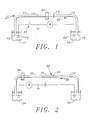
- FIG. 1 shows a diagram of a system for performing capillary zone electrophoresis.
- the system includes two lengths 11, 12 of capillary tubing. Joined at a junction 13 permitting full passage of the carrier liquid 14 for one length of tubing to the other.
- the first 11 is of polymeric material with an inert surface, i.e., typically one which contains little or no surface charge which might give rise to electroosmotic flow or the adsorption of charged species from the carrier liquid 14.
- the second length 12 is of a material susceptible to the formation of an electrokinetic potential, prime examples of which are silica and related materials.
- the open ends 15, 16 of the two lengths tubing are immersed in buffer solutions 17, 18 respectively, each of which contain an electrode 19, 20 across which an electric potential is imposed by a voltage source 21.
- the electroosmotic flow resulting in the electroosmotic region 12 of the tubing is in the direction of the arrow 21.
- the electroosmotic driving force is thus located downstream of the separation zone 11, pulling the carrier liquid 14 through the separation capillary. Injection of the sample is made at an injection point 23 at an upstream end of the separation capillary 11.
- a detector 24 in this case an on-line detector such as a direct capillary optical path detector at a wavelength such as 260 nm.
- the signal generated by the detector is processed in accordance with conventional means for recordation and calculation.
- FIG. 2 The embodiment shown in FIG. 2 is a variation on that shown in FIG. 1.
- the inert capillary 31 and silica capillary 32 are arranged in the same manner as their counterparts in FIG. 1, joined by a similar type of junction 33.
- the open ends of these capillaries are immersed in buffer solutions 34, 35, between which an electric potential is imposed.
- the electric potential is imposed in the opposite direction, resulting in electroosmotic flow in the direction of the arrow 36.
- the electroosmotic region 32 of the capillary system is at the upstream end, and the carrier fluid 37 flows away from the electroosmotic region rather than toward.
- the sample injection point 38 is moved toward the end of the separation capillary 31 which is now the upstream end, and the detector 39 is placed near where the sample injection point 23 of the FIG. 1 embodiment is located.
- This particular arrangement has the advantage that solutes upon separation in the separation region 31 flow directly out of the system, without passing through the electroosmotic region 32, avoiding all possibility of surface contamination of the latter.
Landscapes
- Health & Medical Sciences (AREA)
- Life Sciences & Earth Sciences (AREA)
- Molecular Biology (AREA)
- Chemical & Material Sciences (AREA)
- Biochemistry (AREA)
- Electrochemistry (AREA)
- Physics & Mathematics (AREA)
- Analytical Chemistry (AREA)
- Chemical Kinetics & Catalysis (AREA)
- General Health & Medical Sciences (AREA)
- General Physics & Mathematics (AREA)
- Immunology (AREA)
- Pathology (AREA)
- Electrostatic Separation (AREA)
- Sampling And Sample Adjustment (AREA)
- Peptides Or Proteins (AREA)
- Separation Using Semi-Permeable Membranes (AREA)
Applications Claiming Priority (2)
| Application Number | Priority Date | Filing Date | Title |
|---|---|---|---|
| US07/238,676 US4859301A (en) | 1988-08-30 | 1988-08-30 | Separation of zone formation from electroosmotic impulse in tubular electrophoretic systems |
| US238676 | 1988-08-30 |
Publications (2)
| Publication Number | Publication Date |
|---|---|
| EP0357255A2 true EP0357255A2 (de) | 1990-03-07 |
| EP0357255A3 EP0357255A3 (de) | 1991-10-09 |
Family
ID=22898863
Family Applications (1)
| Application Number | Title | Priority Date | Filing Date |
|---|---|---|---|
| EP19890308010 Ceased EP0357255A3 (de) | 1988-08-30 | 1989-08-07 | Scheidung der Zonenerzeugung vom elektroosmotischen Impuls in Kapillarelektroforesesystemen |
Country Status (3)
| Country | Link |
|---|---|
| US (1) | US4859301A (de) |
| EP (1) | EP0357255A3 (de) |
| JP (1) | JPH0760145B2 (de) |
Cited By (1)
| Publication number | Priority date | Publication date | Assignee | Title |
|---|---|---|---|---|
| EP0397699A1 (de) * | 1987-11-25 | 1990-11-22 | Norberto Guzman | Selbsttätige kapillare elektrophorese-vorrichtung. |
Families Citing this family (11)
| Publication number | Priority date | Publication date | Assignee | Title |
|---|---|---|---|---|
| US5378334A (en) * | 1988-08-24 | 1995-01-03 | The Board Of Trustees Of The Leland Stanford Junior University | System for measuring and controlling electroosmosis in separation techniques |
| US5151164A (en) * | 1990-02-09 | 1992-09-29 | The University Of Maryland | Enhanced capillary zone electrophoresis and apparatus for performance thereof |
| US5246577A (en) * | 1990-05-29 | 1993-09-21 | Millipore Corporation | Apparatus for effecting capillary electrophoresis |
| US5120414A (en) * | 1990-08-30 | 1992-06-09 | Millipore Corporation | Method and apparatus for effecting capillary sample injection into electrophoresis apparatus |
| US5114551A (en) * | 1991-09-30 | 1992-05-19 | Bio-Rad Laboratories, Inc. | Multi-point detection method for electrophoresis and chromatography in capillaries |
| US5409586A (en) * | 1992-08-26 | 1995-04-25 | Hitachi, Ltd. | Method for analyzing nucleic acid or protein and apparatus therefor |
| US6537432B1 (en) | 1998-02-24 | 2003-03-25 | Target Discovery, Inc. | Protein separation via multidimensional electrophoresis |
| NL1010327C2 (nl) * | 1998-10-15 | 2000-04-18 | Univ Twente | Inrichting en werkwijze voor het besturen van een vloeistofstroom. |
| US6818112B2 (en) | 1999-04-20 | 2004-11-16 | Target Discovery, Inc. | Protein separation via multidimensional electrophoresis |
| US6764817B1 (en) | 1999-04-20 | 2004-07-20 | Target Discovery, Inc. | Methods for conducting metabolic analyses |
| US6758953B2 (en) | 1999-10-28 | 2004-07-06 | Nathan A. Thomas | Multistage electrophoresis apparatus and method of use for the separation and purification of cells, particles and solutes |
Citations (3)
| Publication number | Priority date | Publication date | Assignee | Title |
|---|---|---|---|---|
| GB1233907A (de) * | 1967-04-20 | 1971-06-03 | ||
| US4680201A (en) * | 1985-10-30 | 1987-07-14 | Stellan Hjerten | Coating for electrophoresis tube |
| US4690749A (en) * | 1985-12-16 | 1987-09-01 | Universities Space Research Association | Polymer-coated surfaces to control surface zeta potential |
-
1988
- 1988-08-30 US US07/238,676 patent/US4859301A/en not_active Expired - Lifetime
-
1989
- 1989-08-07 EP EP19890308010 patent/EP0357255A3/de not_active Ceased
- 1989-08-30 JP JP1221844A patent/JPH0760145B2/ja not_active Expired - Lifetime
Patent Citations (3)
| Publication number | Priority date | Publication date | Assignee | Title |
|---|---|---|---|---|
| GB1233907A (de) * | 1967-04-20 | 1971-06-03 | ||
| US4680201A (en) * | 1985-10-30 | 1987-07-14 | Stellan Hjerten | Coating for electrophoresis tube |
| US4690749A (en) * | 1985-12-16 | 1987-09-01 | Universities Space Research Association | Polymer-coated surfaces to control surface zeta potential |
Non-Patent Citations (1)
| Title |
|---|
| JOURNAL OF CHROMATOGRAPHY, vol. 99, no. 1, 6th November 1974, pages 23-30, NL; V. PRETORIUS et al.: "Electro-osmosis, a new concept for high-speed liquid chromatography" * |
Cited By (2)
| Publication number | Priority date | Publication date | Assignee | Title |
|---|---|---|---|---|
| EP0397699A1 (de) * | 1987-11-25 | 1990-11-22 | Norberto Guzman | Selbsttätige kapillare elektrophorese-vorrichtung. |
| EP0397699B1 (de) * | 1987-11-25 | 1996-04-03 | GUZMAN, Norberto A. | Selbsttätige kapillare elektrophorese-vorrichtung |
Also Published As
| Publication number | Publication date |
|---|---|
| JPH02168154A (ja) | 1990-06-28 |
| EP0357255A3 (de) | 1991-10-09 |
| US4859301A (en) | 1989-08-22 |
| JPH0760145B2 (ja) | 1995-06-28 |
Similar Documents
| Publication | Publication Date | Title |
|---|---|---|
| Colón et al. | Peer reviewed: capillary electrochromatography | |
| US5141621A (en) | Capillary electrophoresis injection device and method | |
| Jorgenson et al. | Free-zone electrophoresis in glass capillaries. | |
| US5151164A (en) | Enhanced capillary zone electrophoresis and apparatus for performance thereof | |
| EP0454286B1 (de) | Kapillaren für kapillare Elektrophorese mit einem länglichen Querschnitt | |
| US5246577A (en) | Apparatus for effecting capillary electrophoresis | |
| US5942093A (en) | Electro-osmotically driven liquid delivery method and apparatus | |
| Dadoo et al. | Advances in capillary electrochromatography: Rapid and high-efficiency separations of PAHs | |
| Riekkola et al. | Terminology for analytical capillary electromigration techniques (IUPAC Recommendations 2003) | |
| US4859301A (en) | Separation of zone formation from electroosmotic impulse in tubular electrophoretic systems | |
| EP0386925A1 (de) | Zelle für Kapillar-Elektrophorese | |
| US9910011B2 (en) | Isotachophoresis system having larger-diameter channels flowing into channels with reduced diameter and with selectable counter-flow | |
| Wang et al. | Measurement of electroosmotic flow in capillary and microchip electrophoresis | |
| EP0295942B1 (de) | Leitfähigkeitsdetektor in einer Säule, zur elektrokinetischen Trennung in einer Mikrosäule | |
| US5378334A (en) | System for measuring and controlling electroosmosis in separation techniques | |
| US5073239A (en) | Fluid introduction into a capillary by electroendosmosis | |
| US5223114A (en) | On-column conductivity detector for microcolumn electrokinetic separations | |
| US5089099A (en) | Field amplified polarity switching sample injection in capillary zone electrophoresis | |
| Rodriguez et al. | Conventional capillary electrophoresis in comparison with short-capillary capillary electrophoresis and microfabricated glass chip capillary electrophoresis for the analysis of fluorescein isothiocyanate anti-human immunoglobulin G | |
| US5324413A (en) | Electrophoresis capillary with dispersion-inhibiting cross-section | |
| EP0304295A1 (de) | Elektrokinetische Analysemethode und Vorrichtung mit Abführung von Wärme | |
| Everaerts et al. | Electrophoresis versus electrochromatography | |
| Bowerbank et al. | Comprehensive isotachophoresis–capillary zone electrophoresis using directly inserted columns having different diameters with a periodic counterflow and dual ultraviolet detectors | |
| Fujimoto et al. | The use of a microconcentric column in capillary electrophoresis | |
| Guttman | Effect of temperature on separation efficiency in capillary gel electrophoresis |
Legal Events
| Date | Code | Title | Description |
|---|---|---|---|
| PUAI | Public reference made under article 153(3) epc to a published international application that has entered the european phase |
Free format text: ORIGINAL CODE: 0009012 |
|
| AK | Designated contracting states |
Kind code of ref document: A2 Designated state(s): CH DE FR GB IT LI SE |
|
| 17P | Request for examination filed |
Effective date: 19901227 |
|
| PUAL | Search report despatched |
Free format text: ORIGINAL CODE: 0009013 |
|
| AK | Designated contracting states |
Kind code of ref document: A3 Designated state(s): CH DE FR GB IT LI SE |
|
| 17Q | First examination report despatched |
Effective date: 19920225 |
|
| STAA | Information on the status of an ep patent application or granted ep patent |
Free format text: STATUS: THE APPLICATION HAS BEEN REFUSED |
|
| 18R | Application refused |
Effective date: 19931031 |