EP0357085B1 - A coaxial-waveguide phase shifter - Google Patents
A coaxial-waveguide phase shifter Download PDFInfo
- Publication number
- EP0357085B1 EP0357085B1 EP89116207A EP89116207A EP0357085B1 EP 0357085 B1 EP0357085 B1 EP 0357085B1 EP 89116207 A EP89116207 A EP 89116207A EP 89116207 A EP89116207 A EP 89116207A EP 0357085 B1 EP0357085 B1 EP 0357085B1
- Authority
- EP
- European Patent Office
- Prior art keywords
- coaxial
- waveguide
- phase shifter
- irises
- conductor
- Prior art date
- Legal status (The legal status is an assumption and is not a legal conclusion. Google has not performed a legal analysis and makes no representation as to the accuracy of the status listed.)
- Expired - Lifetime
Links
- 210000000554 iris Anatomy 0.000 claims description 29
- 239000004020 conductor Substances 0.000 claims description 20
- 230000010363 phase shift Effects 0.000 claims description 16
- 238000009826 distribution Methods 0.000 claims description 3
- 230000010287 polarization Effects 0.000 description 10
- 238000000034 method Methods 0.000 description 3
- 230000001902 propagating effect Effects 0.000 description 2
- 230000032683 aging Effects 0.000 description 1
- 230000015572 biosynthetic process Effects 0.000 description 1
- 238000004519 manufacturing process Methods 0.000 description 1
- 238000005457 optimization Methods 0.000 description 1
- 230000000737 periodic effect Effects 0.000 description 1
- 238000000926 separation method Methods 0.000 description 1
- 238000005476 soldering Methods 0.000 description 1
- 238000003786 synthesis reaction Methods 0.000 description 1
- 230000000930 thermomechanical effect Effects 0.000 description 1
Images
Classifications
-
- H—ELECTRICITY
- H01—ELECTRIC ELEMENTS
- H01P—WAVEGUIDES; RESONATORS, LINES, OR OTHER DEVICES OF THE WAVEGUIDE TYPE
- H01P1/00—Auxiliary devices
- H01P1/18—Phase-shifters
- H01P1/183—Coaxial phase-shifters
-
- H—ELECTRICITY
- H01—ELECTRIC ELEMENTS
- H01P—WAVEGUIDES; RESONATORS, LINES, OR OTHER DEVICES OF THE WAVEGUIDE TYPE
- H01P1/00—Auxiliary devices
- H01P1/16—Auxiliary devices for mode selection, e.g. mode suppression or mode promotion; for mode conversion
- H01P1/161—Auxiliary devices for mode selection, e.g. mode suppression or mode promotion; for mode conversion sustaining two independent orthogonal modes, e.g. orthomode transducer
-
- H—ELECTRICITY
- H01—ELECTRIC ELEMENTS
- H01P—WAVEGUIDES; RESONATORS, LINES, OR OTHER DEVICES OF THE WAVEGUIDE TYPE
- H01P1/00—Auxiliary devices
- H01P1/165—Auxiliary devices for rotating the plane of polarisation
Definitions
- the present invention refers to devices for telecommunications systems operating at microwaves and more particularly it concerns a coaxial-waveguide phase shifter which consists of a section of coaxial waveguide comprising an external cylindrical conductor with an internal surface and an internal conductor with an external surface, both hollow, which surfaces face each other and have cross sections which present radial asymmetries in orthogonal direcitons at least at some points along the waveguide axis.
- coaxial waveguides consist of a hollow cylindrical conductor, whereinto a second cylindrical conductor is inserted, which is also hollow and coaxial with the external conductor.
- Said guides are used whenever mode TE11 propagation of signals belonging to two different frequency bands, even though very distant from each other, is desired.
- the internal conductor acts as a conventional circular waveguide, wherein signals belonging to the higher frequency band propagate, whilst the region comprised between the external conductor and the internal one acts as a waveguide wherein signals belonging to the lower frequency band propagate.
- the coaxial waveguide presents a pass band, meant as the band comprised between cutoff frequency of mode TE11 and the frequency of the first higher mode, which is wider than the band of the circular waveguide with the same diameter.
- the addition of one or more external cylindrical conductors allows the addition of a corresponding number of frequency bands propagating in the fundamental mode. A great number of information can thus be transmitted, which can be further doubled by using signals belonging to the same frequency band but with different polarizations.
- phase shifter can he used to convert a circular polarization signal into a linear polarization signal, thus operating as a polarizer with a 90° phase shift, or to rotate the polarization of a linearly polarized signal, keeping the polarization linear: in this case phase shift introduced must be of 180°.
- a polarizer with a 90° phase shift allows also the separation of circularly polarized signals with opposite rotation directions, supplying two linearly-polarized orthogonal signals, which can easily be separated.
- a circular waveguide phase shifter has been described in the article entitled “Polarization diversity lowers antenna feed-line noise", by Howard C. Yates et alii, issued in Microwaves, May 1968. It consists of a circular waveguide section, whereinto cascaded irises are placed, composed of two equal circular segments in opposition. A total phase shift of 90 or 180 degrees is obtained by distributing it conveniently on the different irises, generally placed at a quarter-wave spacing at the design-center frequency. Bandwidths of an octave were obtained for 90° ⁇ 1° phase shifts.
- phase shifter For applications on board a satellite light and reduced-encumbrance devices are also required, which entails the search for the optimum number of irises the phase shifter is implemented with, since also total length of the device depends on this number.
- phase shifters designed for circular waveguide systems
- the desired bandwidths were obtained by using a rather high number of irises; hence the structures obtained are cumbersome.
- the coaxial-waveguide phase shifter provided by the present invention, which presents the above-mentioned performances, which is of small dimensions and can be designed rigorously through the exact synthesis of the equivalent electrical network.
- the device is also apt to be used on board a satellite, since dielectric parts are not required which present a thermomechanical behaviour not easily predictable owing to expansions, ageing, soldering operations, etc.
- the present invention provides a coaxial-waveguide phase shifter, characterized in that the radial asymmetries have dimensions which vary along the waveguide axis.
- the phase shifter consists of a coaxial guide section, comprising an external cylindrical conductor CE as well as an internal cylindrical conductor CI, both hollow.
- the internal diameter of the external conductor and the external diameter of the internal conductor are D and d respectively.
- N of irises I fixed to the external conductor. They consist of two opposite plates having the shape of circular segments with rectilinear sides parallel to each other. Plate thickness is T, rectilinear sides are separated by a distance W and spacing between the irises is Li.
- phase shifter depends on the above mechanical parameters, and more particularly on W/D, D/d, T of each iris and on Li and N, which must accurately be defined while designing it.
- W/D, D/d, T of each iris and on Li and N which must accurately be defined while designing it.
- design and optimization of rectangular or circular waveguide phase shifters have been chiefly experimentally carried out, following rather slow and expensive procedures.
- the electrical models used were not apt to represent structures with irises very close to each other.
- phase shifter for instance 90 or 180 degrees, frequency band F1-F2, at which the device is to operate, number N of irises to be inserted into the guide and the distribution of phase shifts ⁇ i allotted to each iris along the guide, e.g. a choice is possible between uniform, binomial, tapered distributions or the like, in function of the performances required as to return losses and bandwidth.
- W/D and L values relating to the last iris can be obtained by using previously prepared design data.
- quadripole equivalent of the cell composed of the guide section and of the iris is derived by expressing the reactances which form it in function of the mechanical characteristics of the iris itself.
- the relations obtained allow the built up of curves of the phase shift ⁇ i introduced by the cell in function of W/D and T of the iris, where the frequency forms the parameter. Said curves can he then directly used or even better computer-memorised and used in the automated design phase.
- the following step is that of implementing the phase shift ⁇ N-1 by combining in cascade the two cells, to obtain new values W/D and L relating to the last iris but one. Since in this case the load is no longer matched due to the last iris presence, it is necessary to calculate the phase shift of the single cell taking into account multiple reflections. Even in this case it is possible to build up the curves of the phase shift to be obtained in function of the phase shift of the isolated single cell where the reflection coefficient is the parameter.
- the process goes on like this up to the obtention of all the iris data.
- the device can also use irises with a different shape from that of two opposite circular segments, provided they do not present radial symmetry, since they have to yield a phase shift between incident signals with orthogonal polarizations.
- Fig 3 shows different shapes of irises.
- the iris denoted by a) consists of two sectors of an annulus and that denoted by b) of two rectangular plates.
- dissymmetry is due to the same internal waveguide presenting a rectangular cross section, while in d) and e) the iris consists of plates having respectively the shapes of circular sector and rectangle, fixed to the internal circular waveguide.
- the design requires the equivalent electrical circuit of the iris used.
Landscapes
- Waveguide Switches, Polarizers, And Phase Shifters (AREA)
Description
- The present invention refers to devices for telecommunications systems operating at microwaves and more particularly it concerns a coaxial-waveguide phase shifter which consists of a section of coaxial waveguide comprising an external cylindrical conductor with an internal surface and an internal conductor with an external surface, both hollow, which surfaces face each other and have cross sections which present radial asymmetries in orthogonal direcitons at least at some points along the waveguide axis.
- As known, coaxial waveguides consist of a hollow cylindrical conductor, whereinto a second cylindrical conductor is inserted, which is also hollow and coaxial with the external conductor.
- Said guides are used whenever mode TE11 propagation of signals belonging to two different frequency bands, even though very distant from each other, is desired. In fact, the internal conductor acts as a conventional circular waveguide, wherein signals belonging to the higher frequency band propagate, whilst the region comprised between the external conductor and the internal one acts as a waveguide wherein signals belonging to the lower frequency band propagate. In addition, the coaxial waveguide presents a pass band, meant as the band comprised between cutoff frequency of mode TE11 and the frequency of the first higher mode, which is wider than the band of the circular waveguide with the same diameter.
- Of course, the addition of one or more external cylindrical conductors allows the addition of a corresponding number of frequency bands propagating in the fundamental mode. A great number of information can thus be transmitted, which can be further doubled by using signals belonging to the same frequency band but with different polarizations.
- Analogously to what already devised for circular waveguide systems, which is hence well known, also for coaxial waveguides it is necessary to design and manufacture devices capable of conveniently handling microwave signals propagating inside. More particularly, since signals belonging to the same frequency band, but with different polarizations (namely orthogonal or with opposite rotation directions), are transmitted through the same guide, discriminating devices are required. Among these, phase shifters, and chiefly phase shifters permitting the obtention of a different electrical behaviour in presence of different-polarization signals, are particularly needed. By these devices highly performant microwave components can he obtained, such as double-polarization multiband feeders for ground station or satellite antennas to be used in telecommunications or in radioastronomy domain.
- In applications of this kind a phase shifter can he used to convert a circular polarization signal into a linear polarization signal, thus operating as a polarizer with a 90° phase shift, or to rotate the polarization of a linearly polarized signal, keeping the polarization linear: in this case phase shift introduced must be of 180°. A polarizer with a 90° phase shift allows also the separation of circularly polarized signals with opposite rotation directions, supplying two linearly-polarized orthogonal signals, which can easily be separated.
- Phase shifters in rectangular or circular waveguides are already known in the literature. A circular waveguide phase shifter has been described in the article entitled "Polarization diversity lowers antenna feed-line noise", by Howard C. Yates et alii, issued in Microwaves, May 1968. It consists of a circular waveguide section, whereinto cascaded irises are placed, composed of two equal circular segments in opposition. A total phase shift of 90 or 180 degrees is obtained by distributing it conveniently on the different irises, generally placed at a quarter-wave spacing at the design-center frequency. Bandwidths of an octave were obtained for 90° ± 1° phase shifts.
- A further waveguide phase shifter has been described in US-A-4 725 795. This device makes use of a periodic structure of the corrugated type. Thus it presents large dimensions and a high number of irises, and the costs to produce it are high.
- The performances required of such components can be summarised:
- bandwidth of at least 12% of the center frequency;
- return losses inferior to 30 dB;
- differential phase shift between orthogonal polarizations of ±1°;
- axial ratio inferior to 1.02, in case of circular polarization.
- For applications on board a satellite light and reduced-encumbrance devices are also required, which entails the search for the optimum number of irises the phase shifter is implemented with, since also total length of the device depends on this number.
- In the known phase shifters, designed for circular waveguide systems, the desired bandwidths were obtained by using a rather high number of irises; hence the structures obtained are cumbersome.
- The inconveniences above are overcome by the coaxial-waveguide phase shifter, provided by the present invention, which presents the above-mentioned performances, which is of small dimensions and can be designed rigorously through the exact synthesis of the equivalent electrical network. The device is also apt to be used on board a satellite, since dielectric parts are not required which present a thermomechanical behaviour not easily predictable owing to expansions, ageing, soldering operations, etc.
- The present invention provides a coaxial-waveguide phase shifter, characterized in that the radial asymmetries have dimensions which vary along the waveguide axis.
- The foregoing and other characteristics of the present invention will be made clearer by the following description of a preferred embodiment thereof, given by way of a non-limiting example, and by the annexed drawings wherein:
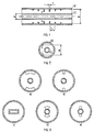
- Fig. 1 is a longitudinal section of the phase shifter;
- Fig. 2 is a cross section of the phase shifter;
- Fig. 3 shows differently-shaped irises.
- As shown in Fig. 1, the phase shifter consists of a coaxial guide section, comprising an external cylindrical conductor CE as well as an internal cylindrical conductor CI, both hollow. The internal diameter of the external conductor and the external diameter of the internal conductor are D and d respectively. There is then a certain number N of irises I fixed to the external conductor. They consist of two opposite plates having the shape of circular segments with rectilinear sides parallel to each other. Plate thickness is T, rectilinear sides are separated by a distance W and spacing between the irises is Li.
- The electrical behaviour of the phase shifter depends on the above mechanical parameters, and more particularly on W/D, D/d, T of each iris and on Li and N, which must accurately be defined while designing it. Up to now, the design and optimization of rectangular or circular waveguide phase shifters have been chiefly experimentally carried out, following rather slow and expensive procedures. Besides, while implementing broad-band devices considerably long structures have been obtained, since the electrical models used were not apt to represent structures with irises very close to each other.
- A design method which is convenient in avoiding these disadvantages will be now described.
- One has first to define total phase shift αTOT introduced by the phase shifter, for instance 90 or 180 degrees, frequency band F1-F2, at which the device is to operate, number N of irises to be inserted into the guide and the distribution of phase shifts αi allotted to each iris along the guide, e.g. a choice is possible between uniform, binomial, tapered distributions or the like, in function of the performances required as to return losses and bandwidth.
- Starting from a matched load and from the last phase shift αN to be obtained, W/D and L values relating to the last iris can be obtained by using previously prepared design data. To this aim, quadripole equivalent of the cell composed of the guide section and of the iris is derived by expressing the reactances which form it in function of the mechanical characteristics of the iris itself. The relations obtained allow the built up of curves of the phase shift αi introduced by the cell in function of W/D and T of the iris, where the frequency forms the parameter. Said curves can he then directly used or even better computer-memorised and used in the automated design phase.
- The following step is that of implementing the phase shift αN-1 by combining in cascade the two cells, to obtain new values W/D and L relating to the last iris but one. Since in this case the load is no longer matched due to the last iris presence, it is necessary to calculate the phase shift of the single cell taking into account multiple reflections. Even in this case it is possible to build up the curves of the phase shift to be obtained in function of the phase shift of the isolated single cell where the reflection coefficient is the parameter.
- The process goes on like this up to the obtention of all the iris data.
- The device can also use irises with a different shape from that of two opposite circular segments, provided they do not present radial symmetry, since they have to yield a phase shift between incident signals with orthogonal polarizations.
- Fig 3 shows different shapes of irises. The iris denoted by a) consists of two sectors of an annulus and that denoted by b) of two rectangular plates. In c) dissymmetry is due to the same internal waveguide presenting a rectangular cross section, while in d) and e) the iris consists of plates having respectively the shapes of circular sector and rectangle, fixed to the internal circular waveguide. Of course, the design requires the equivalent electrical circuit of the iris used.
Claims (6)
- A coaxial-waveguide phase shifter, which consists of a section of coaxial waveguide comprising an external cylindrical conductor (CE) with an internal surface and an internal conductor (Cl) with an external surface, both hollow, which surfaces face each other and have cross sections which present radial asymmetries in orthogonal directions at least at some points along the waveguide axis, characterized in that the radial asymmetries have dimensions which vary along the waveguide axis.
- A coaxial-waveguide phase shifter as in claim 1, characterized in that said internal conductor (Cl) has a circular cross section and said radial asymmetries are irises (I) parallel to each other and with mechanical parameters (W/D; D/d, T) which generate binomial or tapered distributions of the phase shifts along the waveguide axis.
- A coaxial-waveguide phase shifter as in claim 2, characterized in that said irises (I) are internally fixed to the external conductor (CE) and consist of two opposite plates having circular arc shape with the rectilinear sides parallel to each other.
- A coaxial-waveguide phase shifter as in claim 2, characterized in that said irises (I) are internally fixed to the external conductor (CE) and consist of two sectors of an annulus.
- A coaxial-waveguide phase shifter as in claim 2, characterized in that said irises (I) are internally fixed to the external conductor (CE) and consist of two rectangular plates.
- A coaxial-waveguide phase shifter as in claim 2, characterized in that said irises (I) are externally fixed to the internal conductor (CI) and consist of two plates shaped as an annular sector.
Applications Claiming Priority (2)
| Application Number | Priority Date | Filing Date | Title |
|---|---|---|---|
| IT6778788 | 1988-09-02 | ||
| IT8867787A IT1223796B (en) | 1988-09-02 | 1988-09-02 | COAXIAL WAVER GUIDE CHANGER |
Publications (2)
| Publication Number | Publication Date |
|---|---|
| EP0357085A1 EP0357085A1 (en) | 1990-03-07 |
| EP0357085B1 true EP0357085B1 (en) | 1994-08-17 |
Family
ID=11305290
Family Applications (1)
| Application Number | Title | Priority Date | Filing Date |
|---|---|---|---|
| EP89116207A Expired - Lifetime EP0357085B1 (en) | 1988-09-02 | 1989-09-01 | A coaxial-waveguide phase shifter |
Country Status (7)
| Country | Link |
|---|---|
| US (1) | US4982171A (en) |
| EP (1) | EP0357085B1 (en) |
| JP (1) | JPH02113601A (en) |
| AU (1) | AU620637B2 (en) |
| CA (1) | CA1318370C (en) |
| DE (2) | DE357085T1 (en) |
| IT (1) | IT1223796B (en) |
Cited By (1)
| Publication number | Priority date | Publication date | Assignee | Title |
|---|---|---|---|---|
| US7031751B2 (en) | 2001-02-01 | 2006-04-18 | Kathrein-Werke Kg | Control device for adjusting a different slope angle, especially of a mobile radio antenna associated with a base station, and corresponding antenna and corresponding method for modifying the slope angle |
Families Citing this family (13)
| Publication number | Priority date | Publication date | Assignee | Title |
|---|---|---|---|---|
| AU688398B2 (en) * | 1993-10-14 | 1998-03-12 | Andrew Corporation | A variable differential phase shifter |
| US5459442A (en) * | 1995-01-23 | 1995-10-17 | Mcdonnell Douglas Corporation | High power RF phase shifter |
| CN1051883C (en) * | 1996-11-28 | 2000-04-26 | 台扬科技股份有限公司 | Broadband, Short Length Circular Waveguide Phase Shifter |
| JP3657484B2 (en) * | 1999-12-10 | 2005-06-08 | 三菱電機株式会社 | Circularly polarized wave generator |
| IT1319925B1 (en) * | 2000-02-29 | 2003-11-12 | Cselt Centro Studi Lab Telecom | WAVE GUIDE POLARIZATION. |
| WO2001082404A1 (en) | 2000-04-20 | 2001-11-01 | Paratek Microwave, Inc. | Waveguide-finline tunable phase shifter |
| US8786380B2 (en) | 2008-03-28 | 2014-07-22 | Optim Microwave, Inc. | Circular polarizer using stepped conductive and dielectric fins in an annular waveguide |
| US7656246B2 (en) * | 2008-03-28 | 2010-02-02 | Optim Microwave, Inc. | Circular polarizer using conductive and dielectric fins in a coaxial waveguide |
| US8248178B2 (en) * | 2009-12-03 | 2012-08-21 | The Aerospace Corporation | High power waveguide polarizer with broad bandwidth and low loss, and methods of making and using same |
| US8653906B2 (en) | 2011-06-01 | 2014-02-18 | Optim Microwave, Inc. | Opposed port ortho-mode transducer with ridged branch waveguide |
| US8994474B2 (en) | 2012-04-23 | 2015-03-31 | Optim Microwave, Inc. | Ortho-mode transducer with wide bandwidth branch port |
| US9178261B2 (en) * | 2012-07-11 | 2015-11-03 | University Of South Florida | Vertical microcoaxial interconnects |
| DE102015218877B4 (en) * | 2015-09-30 | 2017-08-31 | Airbus Ds Gmbh | Coaxial diplexer and signal coupling device |
Family Cites Families (11)
| Publication number | Priority date | Publication date | Assignee | Title |
|---|---|---|---|---|
| DE934354C (en) * | 1943-12-18 | 1955-10-20 | Funkstrahl Ges Fuer Nachrichte | Arrangement for rotating the phase of ultra-short electromagnetic waves |
| US2783440A (en) * | 1955-01-26 | 1957-02-26 | Lockheed Aircraft Corp | Light weight wave guide construction |
| CH391804A (en) * | 1961-12-08 | 1965-05-15 | Siemens Ag Albis | Transmit / receive switch |
| US3413642A (en) * | 1966-05-05 | 1968-11-26 | Bell Telephone Labor Inc | Dual mode antenna |
| JPS4836986Y1 (en) * | 1970-06-11 | 1973-11-05 | ||
| US3668567A (en) * | 1970-07-02 | 1972-06-06 | Hughes Aircraft Co | Dual mode rotary microwave coupler |
| JPS6030441B2 (en) * | 1977-07-04 | 1985-07-16 | 日本電気株式会社 | Dual frequency band shared phase shifter |
| US4504805A (en) * | 1982-06-04 | 1985-03-12 | Andrew Corporation | Multi-port combiner for multi-frequency microwave signals |
| JPS5977702A (en) * | 1982-10-26 | 1984-05-04 | Nec Corp | Waveguide type phase shifter |
| US4725795A (en) * | 1985-08-19 | 1988-02-16 | Hughes Aircraft Co. | Corrugated ridge waveguide phase shifting structure |
| DE3617560C2 (en) * | 1986-05-24 | 1996-08-14 | Schnell Maschfab Karl | Machine for filling doughy media, in particular sausage meat |
-
1988
- 1988-09-02 IT IT8867787A patent/IT1223796B/en active
-
1989
- 1989-07-24 US US07/384,743 patent/US4982171A/en not_active Expired - Fee Related
- 1989-08-16 AU AU40031/89A patent/AU620637B2/en not_active Ceased
- 1989-08-18 JP JP1211511A patent/JPH02113601A/en active Pending
- 1989-08-30 CA CA000609819A patent/CA1318370C/en not_active Expired - Fee Related
- 1989-09-01 DE DE198989116207T patent/DE357085T1/en active Pending
- 1989-09-01 DE DE68917548T patent/DE68917548T2/en not_active Expired - Fee Related
- 1989-09-01 EP EP89116207A patent/EP0357085B1/en not_active Expired - Lifetime
Cited By (1)
| Publication number | Priority date | Publication date | Assignee | Title |
|---|---|---|---|---|
| US7031751B2 (en) | 2001-02-01 | 2006-04-18 | Kathrein-Werke Kg | Control device for adjusting a different slope angle, especially of a mobile radio antenna associated with a base station, and corresponding antenna and corresponding method for modifying the slope angle |
Also Published As
| Publication number | Publication date |
|---|---|
| AU620637B2 (en) | 1992-02-20 |
| DE68917548D1 (en) | 1994-09-22 |
| DE357085T1 (en) | 1991-06-13 |
| AU4003189A (en) | 1990-03-08 |
| CA1318370C (en) | 1993-05-25 |
| DE68917548T2 (en) | 1995-01-05 |
| EP0357085A1 (en) | 1990-03-07 |
| US4982171A (en) | 1991-01-01 |
| IT1223796B (en) | 1990-09-29 |
| JPH02113601A (en) | 1990-04-25 |
| IT8867787A0 (en) | 1988-09-02 |
Similar Documents
| Publication | Publication Date | Title |
|---|---|---|
| Bulashenko et al. | Analytical technique for iris polarizers development | |
| EP0376540B1 (en) | Compensated microwave feed horn | |
| US5539420A (en) | Multilayered, planar antenna with annular feed slot, passive resonator and spurious wave traps | |
| KR0148253B1 (en) | Flush Surface Wave Antenna | |
| US5995047A (en) | Microstrip antenna device, in particular for telephone transmissions by satellite | |
| US5010348A (en) | Device for exciting a waveguide with circular polarization from a plane antenna | |
| Yang et al. | Novel phase shifter design based on substrate-integrated-waveguide technology | |
| EP1291955B1 (en) | Waveguide group branching filter | |
| US20070024399A1 (en) | Filters and antennas for microwaves and millimetre waves, based on open-loop resonators and planar transmission lines | |
| EP0357085A1 (en) | A coaxial-waveguide phase shifter | |
| US4573056A (en) | Dipole radiator excited by a shielded slot line | |
| US6097264A (en) | Broad band quad ridged polarizer | |
| GB2316233A (en) | Wide band radiating device capable of several polarizations | |
| WO1988010013A2 (en) | Microwave multiplexer with multimode filter | |
| US9431715B1 (en) | Compact wide band, flared horn antenna with launchers for generating circular polarized sum and difference patterns | |
| Cheng et al. | Metasurface concept for mm-wave wideband circularly polarized horns design | |
| US4890117A (en) | Antenna and waveguide mode converter | |
| US2937373A (en) | Slotted waveguide aerials | |
| US5548299A (en) | Collinearly polarized nested cup dipole feed | |
| EP1158594B1 (en) | Generator of circularly polarized wave | |
| CN114914683A (en) | Millimeter wave dual-polarized array element with high isolation and array antenna | |
| US4885556A (en) | Circularly polarized evanescent mode radiator | |
| US4653118A (en) | Printed circuit transition for coupling a waveguide filter to a high frequency microstrip circuit | |
| Chen et al. | W‐band multimode monopulse horn feed for reflector antenna | |
| WO2024094343A1 (en) | Directional coupler |
Legal Events
| Date | Code | Title | Description |
|---|---|---|---|
| PUAI | Public reference made under article 153(3) epc to a published international application that has entered the european phase |
Free format text: ORIGINAL CODE: 0009012 |
|
| AK | Designated contracting states |
Kind code of ref document: A1 Designated state(s): DE FR GB NL |
|
| 17P | Request for examination filed |
Effective date: 19900906 |
|
| TCNL | Nl: translation of patent claims filed | ||
| EL | Fr: translation of claims filed | ||
| DET | De: translation of patent claims | ||
| 17Q | First examination report despatched |
Effective date: 19921210 |
|
| GRAA | (expected) grant |
Free format text: ORIGINAL CODE: 0009210 |
|
| AK | Designated contracting states |
Kind code of ref document: B1 Designated state(s): DE FR GB NL |
|
| REF | Corresponds to: |
Ref document number: 68917548 Country of ref document: DE Date of ref document: 19940922 |
|
| ET | Fr: translation filed | ||
| PLBE | No opposition filed within time limit |
Free format text: ORIGINAL CODE: 0009261 |
|
| STAA | Information on the status of an ep patent application or granted ep patent |
Free format text: STATUS: NO OPPOSITION FILED WITHIN TIME LIMIT |
|
| 26N | No opposition filed | ||
| PGFP | Annual fee paid to national office [announced via postgrant information from national office to epo] |
Ref country code: GB Payment date: 19960823 Year of fee payment: 8 |
|
| PGFP | Annual fee paid to national office [announced via postgrant information from national office to epo] |
Ref country code: DE Payment date: 19960926 Year of fee payment: 8 |
|
| PGFP | Annual fee paid to national office [announced via postgrant information from national office to epo] |
Ref country code: NL Payment date: 19960930 Year of fee payment: 8 Ref country code: FR Payment date: 19960930 Year of fee payment: 8 |
|
| PG25 | Lapsed in a contracting state [announced via postgrant information from national office to epo] |
Ref country code: GB Free format text: LAPSE BECAUSE OF NON-PAYMENT OF DUE FEES Effective date: 19970901 |
|
| PG25 | Lapsed in a contracting state [announced via postgrant information from national office to epo] |
Ref country code: FR Free format text: THE PATENT HAS BEEN ANNULLED BY A DECISION OF A NATIONAL AUTHORITY Effective date: 19970930 |
|
| PG25 | Lapsed in a contracting state [announced via postgrant information from national office to epo] |
Ref country code: NL Free format text: LAPSE BECAUSE OF NON-PAYMENT OF DUE FEES Effective date: 19980401 |
|
| GBPC | Gb: european patent ceased through non-payment of renewal fee |
Effective date: 19970901 |
|
| NLV4 | Nl: lapsed or anulled due to non-payment of the annual fee |
Effective date: 19980401 |
|
| PG25 | Lapsed in a contracting state [announced via postgrant information from national office to epo] |
Ref country code: DE Free format text: LAPSE BECAUSE OF NON-PAYMENT OF DUE FEES Effective date: 19980603 |
|
| REG | Reference to a national code |
Ref country code: FR Ref legal event code: ST |