EP0356884A1 - Firing pin locking device for a firearm - Google Patents
Firing pin locking device for a firearm Download PDFInfo
- Publication number
- EP0356884A1 EP0356884A1 EP89115465A EP89115465A EP0356884A1 EP 0356884 A1 EP0356884 A1 EP 0356884A1 EP 89115465 A EP89115465 A EP 89115465A EP 89115465 A EP89115465 A EP 89115465A EP 0356884 A1 EP0356884 A1 EP 0356884A1
- Authority
- EP
- European Patent Office
- Prior art keywords
- firing pin
- firing
- movement
- locking plunger
- sear
- Prior art date
- Legal status (The legal status is an assumption and is not a legal conclusion. Google has not performed a legal analysis and makes no representation as to the accuracy of the status listed.)
- Withdrawn
Links
Images

Classifications
-
- F—MECHANICAL ENGINEERING; LIGHTING; HEATING; WEAPONS; BLASTING
- F41—WEAPONS
- F41A—FUNCTIONAL FEATURES OR DETAILS COMMON TO BOTH SMALLARMS AND ORDNANCE, e.g. CANNONS; MOUNTINGS FOR SMALLARMS OR ORDNANCE
- F41A17/00—Safety arrangements, e.g. safeties
- F41A17/64—Firing-pin safeties, i.e. means for preventing movement of slidably- mounted strikers
- F41A17/72—Firing-pin safeties, i.e. means for preventing movement of slidably- mounted strikers trigger-operated, i.e. the movement of the trigger bringing a firing-pin safety into inoperative position during the firing
Definitions
- the present invention relates to a firearm including a barrel, a cartridge chamber, a pivotally movable trigger connected to a trigger bar cooperating with a sear reciprocatingly rotatable between a firing position and a rest position, a cockable hammer and a firing pin supported for reciprocating axial movement in a firearm block part, which firing pin upon a pulling of the trigger past the trigger slack is movable by action of the hammer against the force of a restoring spring from a rest position into a firing position to strike against a cartridge located in the cartridge chamber.
- Firearms and specifically handguns of the kind set forth above are bestowed the dangerous drawback of an accidental firing which has in many instances led to an injuring or even killing of a human being.
- Such accident may occur if when, for instance, pulling or drawing, respectively, a gun, the trigger or hammer that accidentally temporarily caught at an obstruction e.g. clothing resulting in a slight moving thereof snaps back into the original position after clearing the obstruction allowing or causing, respectively, a minor movement of the firing pin, which may, however, be sufficient to strike the ignitor with such a force that the gun is fired.
- a further cause may be that the gun can accidentally strike against a hard surface or even being dropped such that the firing pin is moved due to inertial forces resulting again in an accidental and dangerous firing of the gun.
- the invention as claimed is intended to provide a remedy. It solves the problem of how to design a firearm in which the safety lever is located and arranged such on the sear that it allows a movement of the locking plunger into the firing gung unlocking position upon the operating members of the gun reaching the end of the trigger slack such that a movement of the locking plunger into the unlocking position will proceed not earlier than the sear snapping into the firing position.
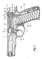
- Fig. 1 illustrates a sectional view of a hundgun, in which the invention is embodied.
- the handgun here a pistol, is generally of a commonly known design such that a detailed description thereof is not necessary for a person skilled in the corresponding art such that only an abridged description thereof is needed for understanding the present invention.
- the handgun includes a barrel 1 ending at a cartridge chamber 2. According to the illustration of fig. 1 a cartridge 10 is loaded in the cartridge chamber 2. A firearm block part 8 housing the firing pin 7 adjoins the cartridge chamber 2. The firing pin 7 is biassed by a restoring pin 9 into its rest position.
- the pivotally movable trigger 3 is connected to a trigger bar 4 cooperating in turn with a reciprocatingly rotatable sear 5 which in turn cooperates with the hammer 6.
- the positions of these four members are shown in the rest position in which the hammer is in the down position.
- the pivotable hammer 6 When the pivotable hammer 6 is cocked, it compresses via a transition link 22 its biassing spring 23.
- the clip 24 for the cartridges including its cartridge feeding spring 25, whereby one cartridge 10′ is shown in the loading position.
- the spring loaded sear 5 When the hammer 6 is cocked, the spring loaded sear 5 is rotated clockwise aroung the pivot axis 26 such to lock the hammer in its fully cocked position.
- the trigger 3 In order to fire the gun the trigger 3 is pulled, based on the illustration of fig. 1, towards the right-hand side such that it rotates around the pivot axis 27 initiating a movement of the trigger bar 4 towards the right based on the illustration.
- the sear 5 Upon overcoming the trigger slack the sear 5 rotates counterclockwise around its pivot axis 26 and releases the hammer 6 which strikes against the rear end 28 of the firing pin 7 which is biassed by the restoring spring 9 into the illustrated position such to propel the firing pin 7 against the cartridge 10 located in the cartridge chamber 2 whereupon the gun is fired.
- fig. 2 which illustrates on a somewhat enlarged scale and somewhat more schematically the part of the handgun which houses the firing pin 7.
- the firing pin 7 is reciprocatingly movable in the direction of its center axis 17.
- the restoring spring 9 illustrated in fig. 1 is omitted in the drawing of fig. 2.
- a locking plunger 11 is located in the firearm block part 8 and reciprocatably movable in a direction perpendicularly to the center axis 17 of the firing pin 7.
- the locking plunger 11 has a through bore 15 with an axis 16 extending parallel to the axis of the firing pin 7.
- a biasing pressure spring 12 biases this locking plunger 11 downwards to continuously abut a safety lever 14.
- the safety lever 14 is now an integral part of the sear 5 (see hereto fig. 1). Referring now to the above explained movements of the structural members of the gun when firing the gun it becomes obvious that upon passing the trigger slack this safety lever 14 will together with the snapping movement of the sear 5 rotate counterclockwise around the pivot axis 26 of the sear 5.
- the firing pin 17 includes a first collar 18.
- This first collar 18 has a diamter which is larger than the inner diamter of the through bore 15 of the locking plunger 11. By abutting the locking plunger 11 this first collar 18 limits accordingly the restoring spring 9 initiated movement of the firing pin 7 into its rest position. Additionally as can be seen in fig. 2 this first collar 18 forms a sliding guide of the firing pin 7 within the firearm block part 8.
- This first collar 18 is axially followed by a first intermediate section 19.
- the outer diamter of this first intermediate section 19 is smaller than the inner diamter of the through bore 15.
- the length of the first intermediate section 19 corresponds to the lenght of the through bore 15 such that in the illustrated locking position it fits axially snugly in the through bore 15 leading as is evident from the drawing to a guiding of the movement of the blocking plunger 11 perpendicularly to the firing pin 7.
- This first intermediate section 19 is in turn followed by a second intermediate section 20.
- the outer diameter of the second intermediate section 20 corresponds such to the inner diameter of the through bore 15 that it can be moved thereinto.
- the axial length of the second intermediate section 20 corresponds roughly to the axial length of the through bore 15 of the locking plunger 11. Accordingly, when the locking plunger 11 has been released by the safety lever 14 of the sear 5 to move downwards, the firing pin 7 is given free to be propelled towards the left by the hammer 6 striking onto its rear end 26, whereby the second intermediate section 20 glides into the through bore 15.
- This second intermediate section 20 is finally followed by a second collar 21.
- the outer diameter of this second collar 21 is larger than the inner diameter of the through bore 15. This second collar 21 limits conclusively the firing movement of the firing pin 7 in that it comes to abut the flank of the locking plunger 11 upon the firing. Additionally, the second collar 21 forms a further axial guiding support of the firing pin 7 in the firearm block part 8.
- the safety lever 14 will start its downwards pivoting movement allowing a corresponding movement of the locking plunger 11 not earlier than the operating members of the firearm have passed the trigger slack. In any other position an axial moving of the firing pin 7 and thus accidental firing of the gun is absolutely impossible such that a large safety regarding an unintentional firing is arrived at.
- the disclosed inventive safety structure acting onto the firing pin is embodied in addition to the generally known normal safety catch of firearms, such as e.g. of the AT 84 pistol of the ITM (Industrial Technology and Machines AG) company.
- the hammer of the AT 84 of the ITM may be brought into three positions, namely: hammer down, half cock and fill cock, and that the present invention is operative in each of the three mentioned hammer positions.
Landscapes
- Engineering & Computer Science (AREA)
- General Engineering & Computer Science (AREA)
- Toys (AREA)
- Portable Nailing Machines And Staplers (AREA)
Abstract
A locking plunger (11) which is perpendicular movable relative to the direction of movement of the firing pin (7) allows or prevents the axial movement of the firing pin to fire the gun. This locking plunger (11) is spring (12) biassed to abut a safety lever (14) which is part of the sear (5) of the operating members of the gun. The safety lever (14) is located and arranged such on the sear (5) that it allows a movement of the locking plunger (11) into the firing pin unlocking position upon the operating members of the gun reaching the end of the trigger slack. Accordingly, a movement of the locking plunger into the unlocking position will proceed not earlier than the sear snapping into the firing position. Any other accidental limited movements of the operating parts of the gun including such of the hammer cannot cause an axial movement of the firing pin because such movmement is positively prevented by the locking plunger. Therefore, an accidental firing of the gun is positively prevented.
Description
- The present invention relates to a firearm including a barrel, a cartridge chamber, a pivotally movable trigger connected to a trigger bar cooperating with a sear reciprocatingly rotatable between a firing position and a rest position, a cockable hammer and a firing pin supported for reciprocating axial movement in a firearm block part, which firing pin upon a pulling of the trigger past the trigger slack is movable by action of the hammer against the force of a restoring spring from a rest position into a firing position to strike against a cartridge located in the cartridge chamber.
- Firearms and specifically handguns of the kind set forth above are bestowed the dangerous drawback of an accidental firing which has in many instances led to an injuring or even killing of a human being. Such accident may occur if when, for instance, pulling or drawing, respectively, a gun, the trigger or hammer that accidentally temporarily caught at an obstruction e.g. clothing resulting in a slight moving thereof snaps back into the original position after clearing the obstruction allowing or causing, respectively, a minor movement of the firing pin, which may, however, be sufficient to strike the ignitor with such a force that the gun is fired. A further cause may be that the gun can accidentally strike against a hard surface or even being dropped such that the firing pin is moved due to inertial forces resulting again in an accidental and dangerous firing of the gun.
- The invention as claimed is intended to provide a remedy. It solves the problem of how to design a firearm in which the safety lever is located and arranged such on the sear that it allows a movement of the locking plunger into the firing gung unlocking position upon the operating members of the gun reaching the end of the trigger slack such that a movement of the locking plunger into the unlocking position will proceed not earlier than the sear snapping into the firing position.
- The advantages offered by the invention are that any accidental and also merely limited movements of the operating parts of the gun including such of the hammer cannot cause an axial movement of the firing gun because such movement is positively prevented by the locking plunger. Therefore, an accidental firing of the gun is positively prevented.
- One way of carrying out the invention is described in detail below with reference to drawings which illustrate only one specific embodiment, in which:
- Fig. 1 is a cross-sectional view of a prt of a handgun incorporating a preferred embodiment of the invention; and
- Fig. 2 illustrates on an enlarged scale more in detail the firing pin and the locking plunger.
- Fig. 1 illustrates a sectional view of a hundgun, in which the invention is embodied. The handgun, here a pistol, is generally of a commonly known design such that a detailed description thereof is not necessary for a person skilled in the corresponding art such that only an abridged description thereof is needed for understanding the present invention.
- The handgun includes a
barrel 1 ending at a cartridge chamber 2. According to the illustration of fig. 1 acartridge 10 is loaded in the cartridge chamber 2. A firearm block part 8 housing thefiring pin 7 adjoins the cartridge chamber 2. Thefiring pin 7 is biassed by a restoringpin 9 into its rest position. - The pivotally movable trigger 3 is connected to a trigger bar 4 cooperating in turn with a reciprocatingly
rotatable sear 5 which in turn cooperates with thehammer 6. The positions of these four members are shown in the rest position in which the hammer is in the down position. When thepivotable hammer 6 is cocked, it compresses via atransition link 22 itsbiassing spring 23. - Also illustrated is the
clip 24 for the cartridges including itscartridge feeding spring 25, whereby onecartridge 10′ is shown in the loading position. - When the
hammer 6 is cocked, the spring loadedsear 5 is rotated clockwise aroung thepivot axis 26 such to lock the hammer in its fully cocked position. In order to fire the gun the trigger 3 is pulled, based on the illustration of fig. 1, towards the right-hand side such that it rotates around thepivot axis 27 initiating a movement of the trigger bar 4 towards the right based on the illustration. Upon overcoming the trigger slack thesear 5 rotates counterclockwise around itspivot axis 26 and releases thehammer 6 which strikes against therear end 28 of thefiring pin 7 which is biassed by the restoringspring 9 into the illustrated position such to propel thefiring pin 7 against thecartridge 10 located in the cartridge chamber 2 whereupon the gun is fired. - All above mentioned structural members and operational movements are commonly known inthe art.
- In order now to prevent an accidental firing due to the reasons set forth above a safety arrangement embodying the present invention is integrated in the handgun.
- Attention is now drawn to fig. 2 which illustrates on a somewhat enlarged scale and somewhat more schematically the part of the handgun which houses the
firing pin 7. Thefiring pin 7 is reciprocatingly movable in the direction of itscenter axis 17. For the sake of clarity the restoringspring 9 illustrated in fig. 1 is omitted in the drawing of fig. 2. Alocking plunger 11 is located in the firearm block part 8 and reciprocatably movable in a direction perpendicularly to thecenter axis 17 of thefiring pin 7. Thelocking plunger 11 has a throughbore 15 with anaxis 16 extending parallel to the axis of thefiring pin 7. Abiasing pressure spring 12 biases this locking plunger 11 downwards to continuously abut asafety lever 14. Thesafety lever 14 is now an integral part of the sear 5 (see hereto fig. 1). Referring now to the above explained movements of the structural members of the gun when firing the gun it becomes obvious that upon passing the trigger slack thissafety lever 14 will together with the snapping movement of thesear 5 rotate counterclockwise around thepivot axis 26 of thesear 5. - Important to note is here that mentioned rotating movement of the
safety lever 14 occurs not earlier than after the passing of the trigger slack such that in all positions of e.g. the trigger 3 thelocking plunger 11 remains in the locking position illustrated in fig. 2. In this position thefiring pin 7 is blocked such that it cannot move in either of the two axial directions defined by theaxis 17. - The
firing pin 17 includes afirst collar 18. Thisfirst collar 18 has a diamter which is larger than the inner diamter of the throughbore 15 of thelocking plunger 11. By abutting the locking plunger 11 thisfirst collar 18 limits accordingly the restoringspring 9 initiated movement of thefiring pin 7 into its rest position. Additionally as can be seen in fig. 2 thisfirst collar 18 forms a sliding guide of thefiring pin 7 within the firearm block part 8. - This
first collar 18 is axially followed by a firstintermediate section 19. The outer diamter of this firstintermediate section 19 is smaller than the inner diamter of the throughbore 15. The length of the firstintermediate section 19 corresponds to the lenght of thethrough bore 15 such that in the illustrated locking position it fits axially snugly in thethrough bore 15 leading as is evident from the drawing to a guiding of the movement of theblocking plunger 11 perpendicularly to thefiring pin 7. - This first
intermediate section 19 is in turn followed by a secondintermediate section 20. The outer diameter of the secondintermediate section 20 corresponds such to the inner diameter of thethrough bore 15 that it can be moved thereinto. The axial length of the secondintermediate section 20 corresponds roughly to the axial length of thethrough bore 15 of thelocking plunger 11. Accordingly, when thelocking plunger 11 has been released by thesafety lever 14 of thesear 5 to move downwards, thefiring pin 7 is given free to be propelled towards the left by thehammer 6 striking onto itsrear end 26, whereby the secondintermediate section 20 glides into thethrough bore 15. - This second
intermediate section 20 is finally followed by asecond collar 21. The outer diameter of thissecond collar 21 is larger than the inner diameter of thethrough bore 15. Thissecond collar 21 limits conclusively the firing movement of thefiring pin 7 in that it comes to abut the flank of the locking plunger 11 upon the firing. Additionally, thesecond collar 21 forms a further axial guiding support of thefiring pin 7 in the firearm block part 8. - It has been said above that the
safety lever 14 will start its downwards pivoting movement allowing a corresponding movement of the locking plunger 11 not earlier than the operating members of the firearm have passed the trigger slack. In any other position an axial moving of thefiring pin 7 and thus accidental firing of the gun is absolutely impossible such that a large safety regarding an unintentional firing is arrived at. - It shall be noted that the disclosed inventive safety structure acting onto the firing pin is embodied in addition to the generally known normal safety catch of firearms, such as e.g. of the AT 84 pistol of the ITM (Industrial Technology and Machines AG) company. Specifically to be noted is that the hammer of the AT 84 of the ITM may be brought into three positions, namely: hammer down, half cock and fill cock, and that the present invention is operative in each of the three mentioned hammer positions.
Claims (3)
1. A firearm, including a barrel, a cartridge chamber, a pivotally movable trigger connected to a trigger bar cooperating with a sear reciprocatingly rotatable between a firing position and a rest position, a cockable hammer, and a firing pin supproted for reciprocating axial movement in a firearm block part, which firing pin upon a pulling of the trigger past the trigger slack is movable by action of said hammer against the force of a restoring spring from a rest position into a firing position to strike against a cartridge located in said cartridge chamber, characterized by a spring loaded locking plunger supported in said block for a reciprocating movement between a locking position preventing an axial movement of said firing pin and a release position allowing an axial movement of said firing pin, which rotatable sear comprises further a safety lever abutting the locking plunger and located such that in the rest position of the sear the safety lever urges the locking plunger against the force of the spring acting thereupon into its firing gun locking position and in the firing position of the sear it releases the locking plunger allowing a spring actuated movement thereof into its firing pin release position.
2. The firearm of claim 1, characterized in that the safety lever is located and arranged such that its position of releasing the locking plunger coincides with the position of the sear at the end of the trigger slack.
3. The firearm of claim 1, characterized in that the locking plunger is guided to move perpendicularly relative to the firing pin and includes a through bore having a center axis extending in the direction of the longitudinal axis of the firing pin, further in that the firing pin includes a first collar axially followed by a first intermediate section, followed in turn by a second intermediate section, followed finally by a second collar, which first collar is located at the smallest and which second collar is located at the largest distance from the tip of the firing pin, which first collar has an outer diameter which is larger than the inner diameter of the through bore whereby an abutment stop is formed limiting the spring initiated restoring movement of the firing pin, which first intermediate section has an outer diameter which is smaller than the inner diameter and an axial length corresponding to the axial length of the through bore, which second intermediate section has an outer diameter corresponding to the inner diameter of the through bore such to be receivable therein and has an axial length corresponding to the axial length of the through bore, which second collar has an outer diameter which is larger than the inner diameter of the through bore whereby a further abutment stop is formed limiting the hammer initiated firing movement of the firing pin.
Applications Claiming Priority (2)
| Application Number | Priority Date | Filing Date | Title |
|---|---|---|---|
| US236020 | 1988-08-24 | ||
| US07/236,020 US4843748A (en) | 1988-08-24 | 1988-08-24 | Firearm |
Publications (1)
| Publication Number | Publication Date |
|---|---|
| EP0356884A1 true EP0356884A1 (en) | 1990-03-07 |
Family
ID=22887791
Family Applications (1)
| Application Number | Title | Priority Date | Filing Date |
|---|---|---|---|
| EP89115465A Withdrawn EP0356884A1 (en) | 1988-08-24 | 1989-08-22 | Firing pin locking device for a firearm |
Country Status (4)
| Country | Link |
|---|---|
| US (1) | US4843748A (en) |
| EP (1) | EP0356884A1 (en) |
| CS (1) | CS274585B2 (en) |
| ES (1) | ES2018131A4 (en) |
Cited By (1)
| Publication number | Priority date | Publication date | Assignee | Title |
|---|---|---|---|---|
| WO2006092706A1 (en) | 2005-03-02 | 2006-09-08 | Industrias El Gamo, Sa | Compressed gas operated pistol |
Families Citing this family (8)
| Publication number | Priority date | Publication date | Assignee | Title |
|---|---|---|---|---|
| US5245776A (en) * | 1990-06-12 | 1993-09-21 | Richard A. Voit | Firearm having improved safety and accuracy features |
| US5625971A (en) * | 1995-10-31 | 1997-05-06 | Martin Tuma | Handgun |
| AT411934B (en) * | 1998-07-14 | 2004-07-26 | Steyr Mannlicher Holding Gmbh | GUN WITH PISTON LOCK |
| US6405470B1 (en) | 2000-06-14 | 2002-06-18 | Travis R. Strahan | Firearm safety lock |
| EP1566606B1 (en) * | 2004-02-19 | 2006-09-13 | S.A.T. Swiss Arms Technology AG | Safety for a hand firearm |
| US7703230B2 (en) * | 2004-12-22 | 2010-04-27 | Smith & Wesson Corp. | Positive striker lock safety for use with a firearm |
| US8296990B2 (en) * | 2008-12-30 | 2012-10-30 | Smith & Wesson Corp. | Snap-on dovetail pistol sight |
| US8443537B2 (en) * | 2011-09-23 | 2013-05-21 | Smith & Wesson Corp. | Drop safety for a firing pin of a firearm |
Citations (2)
| Publication number | Priority date | Publication date | Assignee | Title |
|---|---|---|---|---|
| FR2104121A5 (en) * | 1970-08-24 | 1972-04-14 | Sig Schweiz Industrieges | |
| US4021995A (en) * | 1975-11-10 | 1977-05-10 | Hesston Corporation | Crop conditioning rotor |
Family Cites Families (3)
| Publication number | Priority date | Publication date | Assignee | Title |
|---|---|---|---|---|
| DE2212211C3 (en) * | 1972-03-14 | 1978-08-10 | Fa. Carl Walther, 7900 Ulm | Firing pin safety device for handguns |
| US4021955A (en) * | 1976-05-03 | 1977-05-10 | Colt Industries Operating Corporation (Firearms Division) | Firing pin locking device and method |
| US4658529A (en) * | 1984-08-15 | 1987-04-21 | William Bertolini | Firing pin safety mechanism |
-
1988
- 1988-08-24 US US07/236,020 patent/US4843748A/en not_active Expired - Fee Related
-
1989
- 1989-08-22 EP EP89115465A patent/EP0356884A1/en not_active Withdrawn
- 1989-08-22 ES ES89115465T patent/ES2018131A4/en active Pending
- 1989-08-22 CS CS492589A patent/CS274585B2/en not_active IP Right Cessation
Patent Citations (2)
| Publication number | Priority date | Publication date | Assignee | Title |
|---|---|---|---|---|
| FR2104121A5 (en) * | 1970-08-24 | 1972-04-14 | Sig Schweiz Industrieges | |
| US4021995A (en) * | 1975-11-10 | 1977-05-10 | Hesston Corporation | Crop conditioning rotor |
Cited By (2)
| Publication number | Priority date | Publication date | Assignee | Title |
|---|---|---|---|---|
| WO2006092706A1 (en) | 2005-03-02 | 2006-09-08 | Industrias El Gamo, Sa | Compressed gas operated pistol |
| US7665455B2 (en) | 2005-03-02 | 2010-02-23 | Industrias El Gamo, Sa | Compressed gas operated pistol |
Also Published As
| Publication number | Publication date |
|---|---|
| CS492589A2 (en) | 1990-10-12 |
| CS274585B2 (en) | 1991-08-13 |
| ES2018131A4 (en) | 1991-04-01 |
| US4843748A (en) | 1989-07-04 |
Similar Documents
| Publication | Publication Date | Title |
|---|---|---|
| US5680722A (en) | Fire control system for firearms | |
| US5303494A (en) | Handgun having a decocking/safety control device | |
| US6070512A (en) | Handgun and method of operating handgun | |
| US5417001A (en) | Firing mechanism for fire arms | |
| US5625971A (en) | Handgun | |
| US6240670B1 (en) | Locking mechanism for firearms | |
| US6457271B1 (en) | Magazine safety | |
| US6374526B1 (en) | Firing pin block for pistol | |
| EP2019959B1 (en) | Locking mechanism of a hand firearm | |
| EP0186703A1 (en) | Pistol mechanism for blocking firing pin. | |
| EP0356884A1 (en) | Firing pin locking device for a firearm | |
| KR100556003B1 (en) | Trigger device for a rapid fire handgun | |
| US5992075A (en) | Repeating gun having an axially guided repeating unit | |
| US3942278A (en) | Firing pin safety device for hand firearms | |
| US6948273B2 (en) | Safety mechanism for gun | |
| US4313274A (en) | Firing pin safety device for hand firearms | |
| US4004364A (en) | Rotatably mounted sear | |
| US6604312B2 (en) | Safety units for a hammer in a firearm | |
| KR100360014B1 (en) | Cocking trigger device | |
| WO1987003952A1 (en) | Firearms | |
| US4016669A (en) | Firearm having trigger blocking mechanism | |
| EP1106955B1 (en) | Firearm having inertia striker mechanism | |
| US4866869A (en) | Sear for trigger mechanism | |
| US4067309A (en) | Air gun with trigger mechanism therefor | |
| US4395839A (en) | Firing pin safety device for firearms |
Legal Events
| Date | Code | Title | Description |
|---|---|---|---|
| PUAI | Public reference made under article 153(3) epc to a published international application that has entered the european phase |
Free format text: ORIGINAL CODE: 0009012 |
|
| AK | Designated contracting states |
Kind code of ref document: A1 Designated state(s): ES FR GB IT |
|
| ITCL | It: translation for ep claims filed |
Representative=s name: STUDIO GIOVANNI LECCE & C. S.R.L. |
|
| EL | Fr: translation of claims filed | ||
| 17P | Request for examination filed |
Effective date: 19900811 |
|
| 17Q | First examination report despatched |
Effective date: 19910911 |
|
| STAA | Information on the status of an ep patent application or granted ep patent |
Free format text: STATUS: THE APPLICATION IS DEEMED TO BE WITHDRAWN |
|
| 18D | Application deemed to be withdrawn |
Effective date: 19920812 |