EP0356793B1 - Frein à disque ou embrayage - Google Patents
Frein à disque ou embrayage Download PDFInfo
- Publication number
- EP0356793B1 EP0356793B1 EP89114912A EP89114912A EP0356793B1 EP 0356793 B1 EP0356793 B1 EP 0356793B1 EP 89114912 A EP89114912 A EP 89114912A EP 89114912 A EP89114912 A EP 89114912A EP 0356793 B1 EP0356793 B1 EP 0356793B1
- Authority
- EP
- European Patent Office
- Prior art keywords
- annular
- reaction member
- disc
- axially
- movable
- Prior art date
- Legal status (The legal status is an assumption and is not a legal conclusion. Google has not performed a legal analysis and makes no representation as to the accuracy of the status listed.)
- Expired - Lifetime
Links
Images


Classifications
-
- F—MECHANICAL ENGINEERING; LIGHTING; HEATING; WEAPONS; BLASTING
- F16—ENGINEERING ELEMENTS AND UNITS; GENERAL MEASURES FOR PRODUCING AND MAINTAINING EFFECTIVE FUNCTIONING OF MACHINES OR INSTALLATIONS; THERMAL INSULATION IN GENERAL
- F16D—COUPLINGS FOR TRANSMITTING ROTATION; CLUTCHES; BRAKES
- F16D25/00—Fluid-actuated clutches
- F16D25/06—Fluid-actuated clutches in which the fluid actuates a piston incorporated in, i.e. rotating with the clutch
- F16D25/062—Fluid-actuated clutches in which the fluid actuates a piston incorporated in, i.e. rotating with the clutch the clutch having friction surfaces
- F16D25/063—Fluid-actuated clutches in which the fluid actuates a piston incorporated in, i.e. rotating with the clutch the clutch having friction surfaces with clutch members exclusively moving axially
- F16D25/0635—Fluid-actuated clutches in which the fluid actuates a piston incorporated in, i.e. rotating with the clutch the clutch having friction surfaces with clutch members exclusively moving axially with flat friction surfaces, e.g. discs
-
- F—MECHANICAL ENGINEERING; LIGHTING; HEATING; WEAPONS; BLASTING
- F16—ENGINEERING ELEMENTS AND UNITS; GENERAL MEASURES FOR PRODUCING AND MAINTAINING EFFECTIVE FUNCTIONING OF MACHINES OR INSTALLATIONS; THERMAL INSULATION IN GENERAL
- F16D—COUPLINGS FOR TRANSMITTING ROTATION; CLUTCHES; BRAKES
- F16D55/00—Brakes with substantially-radial braking surfaces pressed together in axial direction, e.g. disc brakes
- F16D55/24—Brakes with substantially-radial braking surfaces pressed together in axial direction, e.g. disc brakes with a plurality of axially-movable discs, lamellae, or pads, pressed from one side towards an axially-located member
- F16D55/26—Brakes with substantially-radial braking surfaces pressed together in axial direction, e.g. disc brakes with a plurality of axially-movable discs, lamellae, or pads, pressed from one side towards an axially-located member without self-tightening action
- F16D55/28—Brakes with only one rotating disc
- F16D55/30—Brakes with only one rotating disc mechanically actuated
-
- F—MECHANICAL ENGINEERING; LIGHTING; HEATING; WEAPONS; BLASTING
- F16—ENGINEERING ELEMENTS AND UNITS; GENERAL MEASURES FOR PRODUCING AND MAINTAINING EFFECTIVE FUNCTIONING OF MACHINES OR INSTALLATIONS; THERMAL INSULATION IN GENERAL
- F16D—COUPLINGS FOR TRANSMITTING ROTATION; CLUTCHES; BRAKES
- F16D59/00—Self-acting brakes, e.g. coming into operation at a predetermined speed
- F16D59/02—Self-acting brakes, e.g. coming into operation at a predetermined speed spring-loaded and adapted to be released by mechanical, fluid, or electromagnetic means
Definitions
- This invention relates to air cooled or water cooled disc brakes in which the brake is applied by a spring and released by air pressure or vise versa e.g. the brake is applied by air and released by springs. It will appreciated by those skilled in the art that the invention in its broader sense may be applicable to any such disc type brake or clutch or torque transmitting device whether air cooled or liquid cooled.
- Torque transmitting devices of the disc type are known in the art and generally comprise an external housing which carries and positions annular axially moveable and fixed reaction members having a disc therebetween.
- U.S. Patent No. 3,398,822 to Eakin discloses an air cooled spring applied brake or clutch which is air released by pressurization of a pressure chamber to axially move an end plate and pressure plate to overcome the force of the springs.
- the brake disc in the Eakin patent is provided with a spline coacting with an externally splined hub 10. Naturally the spline connection between the brake disc and the hub permits the brake disc to slide axially along the hub but necessarily restricts the diameter of the drive shaft.
- this arrangement eliminates the cost of cutting splined and/or gear teeth both in the hub and the rotor of the prior art friction disc assembly.
- Another object of the invention is to provide a substantial commonality of components between spring applied and air applied devices in which a first plurality of connecting means secure a pair of fixed reaction members together and which extend through openings in one of a pair of moveable reaction members which are clamped between a second plurality of connecting means.
- Another object of the invention is to provide a torque transmitting device in which connecting means for the axially moveable members and the axially fixed members are positioned radially outwardly of the rotor disc and the reaction members.
- the spring applied brake 10 includes a rotatable brake assembly which includes a rotatable input shaft 11 and an annular radially disposed brake disc 12 which is secured to the shaft 11 for rotation in unison therewith but mounted for limited axial movement along the shaft 11.
- the brake disc 12 is provided with a plurality of circumferentially faced holes 13 along its inner periphery.
- a stud or bolt 14 extends through each hole 13 and is threaded secured to an annular ring member 15 which is keyed, welded, or otherwise secured to the shaft 11.
- Each of the studs or bolts 14 may be provided with a head 16 to limit the axial movement of the brake disc 12 along the stud 14.
- the brake assembly 10 also has a non-rotating structure which includes a rigid, fixed assembly 19 and a rigid axially moveable assembly 20.
- the axially fixed assembly 19 includes a fixed spring housing 23 shown in Figs. 3 and 4 and a fixed reaction disc member 21 rigidly mounted to a stationary support S by fasteners 22.
- the disc 21 and spring housing 23 are secured together by the studs or bolts 24 passing through the spacer tubes 25 and also through a hole 26 in the spring housing 23.
- the holes 26, the spacer tubes 25, and studs 24 are circumferentially spaced apart at the radially outer periphery of the housing 23.
- the ends of the spacer tubes 25 bear against the axially facing surfaces of the disc 21 and the spring housing 23 and the studs 24 secure the tubes 25 to the disc 21 and spring housing 23 to form an assembly 19.
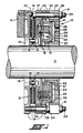
- the axially movable assembly 20 includes a pressure plate 27, shown in Figs. 5 and 6, which is secured to the cylinder member 28 by the studs or bolts 29 passing through holes 34 in the plate 27 and in the spacer tubes 30 which are circumferentially spaced apart at the radially outer periphery thereof.
- the studs 29 pass through holes in the cylinder member 28 and are secured by the nuts 31.
- the studs 29 and tubes 30 also pass through holes 32 in the spring housing 23 and the tubes 25 pass through holes 33 in the pressure plate 27 so that the unitary assembly 20 is moveable axially as a unit.
- the movable assembly 20 is thus axially slideable a limited distance relative to the axial fixed assembly 19 with the studs 29 and tubes 30 of the assembly 20 slideable through the holes 32 in the spring housing 23. Also, the movable assembly 20 is supported for axial movement by the annular radially inner facing surface of the spring housing 23 slideably supported on the annular radially outer facing surfaces 42 of the cylinder member 28.
- the axially moveable assembly 20 is normally biased to the left of Fig. 1, by a plurality of springs 35 so that the pressure plate 27 bears against the friction disc 18.
- One end of each of the springs 35 is positioned within a depression 36 in the pressure plate 27.
- the other end of each of the springs 35 surrounds a projection 37 in the spring housing.
- Each of the projections 37, the depressions 36 and the springs 35 are of course axially aligned and are located radially inwardly of the respective studs 24 and tubes 25 as well as the studs 29 and spacer tubes 30.
- the brake is released by injecting a pressurized fluid into the pressure chamber 38 defined by the annular face 40 of the spring housing 23 having suitable radially inner and outer seals 41 in sealing engagement with the radially facing surfaces 42 and the annular axially facing end surface 43 formed in the cylinder member 28.
- pressurized fluid is injected through the orifices 39 into the chamber 38, the axial moveable assembly 20 is moved to the right of Fig. 1 so that the pressure plate 27 thereof is moved a slight distance away from the friction disc 18, thus compressing the springs 35 and releasing the brake.
- the brake disc 12 will move a slight distance along the bolt 14 so that braking forces are relieved between the fixed reaction disc 21 and the friction disc 18.
- the axially fixed assembly 19 includes a fixed spring housing 23, a fixed reaction disc member 21 which are secured together by the studs 24 passing through spacer tubes 25 and also through holes in the housing 23 and disc member 21.
- the spacer tubes 25 and studs 24 are circumferentially spaced apart at the radially outer periphery of the spring housing 23, in a similar manner to that shown in Fig. 1.
- the axially moveable assembly 20 of the modification shown in Fig. 7 includes a pressure plate 27 which is secured to the cylinder member 28 by studs 29 passing through holes in the pressure plate and in the spacer members 30 which are circumferentially spaced apart at the radially inner periphery thereof.
- the spring housing 23 includes a plurality of radially spaced cup-shaped members 44 at the radially outer most periphery thereof for housing the springs 35.
- the cup-shaped members 44 are positioned radially outwardly of the studs 29 and spacer members 30.
- the pressure chamber 38 is located radially between the inner studs 29 and spacer members 30 and the outer studs 24 and spacer tubes 25 with the chamber 38 located axially intermediate the ends of the inner studs 29.
- the brake shown in Fig. 7 is released by injecting pressurized fluid into the pressure chamber 38 through the orifices 39 to move the axial moveable assembly 20, thereby compressing the springs 35 and releasing the brake.
Landscapes
- Engineering & Computer Science (AREA)
- General Engineering & Computer Science (AREA)
- Mechanical Engineering (AREA)
- Physics & Mathematics (AREA)
- Electromagnetism (AREA)
- Braking Arrangements (AREA)
- Hydraulic Clutches, Magnetic Clutches, Fluid Clutches, And Fluid Joints (AREA)
Claims (10)
- Dispositif de couplage appliqué par ressort (10) comprenant :
un arbre d'entrée (11) tournant relativement;
un disque rotor s'étendant radialement vers l'extérieur (12) comprenant des surfaces périphériques interne et externe et un moyen (14) (15) pour monter ledit disque tournant avec ledit arbre d'entrée (12);
une première pièce annulaire de réaction fixe axialement (21) adjacente d'un coté audit disque rotor (12);
une seconde pièce de réaction annulaire de réaction fixe axialement (23) placée sur le coté opposé dudit disque rotor (12);
une pluralité d'un premier moyen de connexion (24) (25) pour relier ladite première pièce de réaction et ladite seconde pièce de réaction fixe axialement dans une relation d'espacement fixe, tout de ladite pluralité du moyen de connexion s'étendant axialement et tout est positionné radialement vers l'extérieur de ladite surface périphérique externe dudit disque rotor (12);
une première pièce de réaction annulaire mobile axialement (27) placée entre ledit coté opposé dudit disque rotor (12) et ladite seconde pièce de réaction fixe axialement (23);
une seconde pièce de réaction annulaire mobile respectivement (28);
une pluralité de seconds moyens de liaison (29, 30) pour relier ensemble ladite première pièce et ladite seconde pièce de réaction mobile séparées par une distance axiale fixe, tout de ladite pluralité du moyen de connexion s'étendant axialement et tout étant placé radialement vers l'extérieur de la dite surface périphérique externe dudit disque rotor;
un disque annulaire d'une matière pour friction (18) fixée entre chaque coté s'étendant radialement dudit disque rotor, de ladite première pièce de réaction fixe et de ladite première pièce de réaction mobile;
des moyens à ressort (35) entre ladite première pièce de réaction mobile axialement (27) et ladite seconde pièce de réaction fixe respectivement (23) pour pousser ladite pièce de réaction mobile dans un contact par friction avec ledit disque;
ladite seconde pièce de réaction fixe (23) et la seconde pièce de réaction mobile (28) formant une chambre de pression annulaire (38) qui, lorsqu'elle est mise sous pression, provoque le déplacement de ladite pièce mobile axialement en s'écartant dudit disque rotor en comprimant ledit moyen ressort et, dégage ladite première pièce de réaction annulaire axialement mobile, dudit disque. - Dispositif de couplage appliqué par ressort selon la revendication 1 dans lequel ladite première pièce de réaction mobile (27) est montée de manière coulissante sur ledit premier moyen de liaison (24,25).
- Dispositif de couplage appliqué par ressort selon la revendication 2 dans lequel ledit premier moyen de connexion (24, 25) comprend un tube d'espacement (25) placé entre ladite première pièce de réaction et ladite seconde pièce de réaction fixe respectivement et un moyen de fixation (24) pour fixer ensemble ladite première pièce de réaction et ladite seconde pièce de réaction.
- Dispositif de couplage appliqué par ressort selon la revendication 3 dans lequel ledit moyen de fixation (24) passe à travers ledit moyen d'espacement (25) tubulaire.
- Dispositif de couplage appliqué par ressort selon la revendication 1 dans lequel ledit second moyen de liaison (29,30) comprend un tube d'espacement (30) placé entre ladite première pièce de réaction et ladite seconde pièce de réaction mobile et ledit moyen de fixation (29) pour fixer ensemble ladite première pièce de réaction et ladite seconde pièce de réaction.
- Dispositif de couplage appliqué par ressort selon la revendication 5 dans lequel ledit moyen de fixation (29) passe à travers ledit moyen d'espacement (30) tubulaire.
- Dispositif de couplage appliqué par ressort selon la revendication 1 dans lequel chacune desdites pluralité dudit premier moyen (24, 25) et dudit second moyen (29, 30) de liaison est décalée sur la circonférence et elle est accessible par un coté dudit dispositif.
- Dispositif de couplage appliqué par ressort selon la revendication 1 dans laquelle ladite chambre sous pression (38) est placée radialement à l'intérieur dudit premier et dudit second moyen de connexion.
- Dispositif de couplage appliqué par ressort (10) selon la revendication 1 dans lequel ladite seconde pièce de réaction fixe (23) comprend un piston annulaire, ladite seconde pièce de réaction mobile (28) comprend une chambre annulaire recevant ledit piston annulaire dans celle-ci et définissant ladite chambre de pression annulaire (38) entre ledit piston annulaire et ladite chambre annulaire, ladite chambre de pression annulaire 38 lorsqu'elle est mise sous pression, produit le mouvement de ladite seconde pièce de réaction mobile (28) par rapport audit piston annulaire (23) pour comprimer ledit moyen ressort (35) et elle dégage ladite première pièce de réaction annulaire (27) dudit disque (12).
- Dispositif de couplage appliqué par ressort (10) selon la revendication 1 dans lequel ledit second moyen de connexion (29,30) comprend un tube d'espacement (30) placé entre ladite première pièce et ladite seconde pièce de réaction mobile et un moyen de fixation (29) passant à travers ledit moyen d'espacement (30) tubulaire pour fixer ensemble ladite première pièce et ladite seconde pièce de réaction; et
dans lequel ladite seconde pièce de réaction fixe (23) comprend un piston annulaire, ladite seconde pièce de réaction mobile (28) comprend une chambre annulaire recevant ledit piston annulaire dans celle-ci et définissant ladite chambre de pression annulaire (38) entre ledit piston annulaire et ladite chambre annulaire, ladite chambre de pression annulaire (38) lorsqu'elle est mise sous pression, produit le mouvement de ladite seconde pièce de réaction mobile (28) par rapport audit piston annulaire (23) pour comprimer ledit moyen ressort (35) et elle dégage ladite première pièce de réaction annulaire (27) dudit disque (12).
Applications Claiming Priority (2)
| Application Number | Priority Date | Filing Date | Title |
|---|---|---|---|
| US237792 | 1988-08-29 | ||
| US07/237,792 US4907683A (en) | 1988-08-29 | 1988-08-29 | Disc brake or clutch |
Publications (2)
| Publication Number | Publication Date |
|---|---|
| EP0356793A1 EP0356793A1 (fr) | 1990-03-07 |
| EP0356793B1 true EP0356793B1 (fr) | 1993-02-24 |
Family
ID=22895202
Family Applications (1)
| Application Number | Title | Priority Date | Filing Date |
|---|---|---|---|
| EP89114912A Expired - Lifetime EP0356793B1 (fr) | 1988-08-29 | 1989-08-11 | Frein à disque ou embrayage |
Country Status (6)
| Country | Link |
|---|---|
| US (1) | US4907683A (fr) |
| EP (1) | EP0356793B1 (fr) |
| JP (1) | JP2820446B2 (fr) |
| CA (1) | CA1308050C (fr) |
| DE (1) | DE68905011T2 (fr) |
| ES (1) | ES2038384T3 (fr) |
Families Citing this family (18)
| Publication number | Priority date | Publication date | Assignee | Title |
|---|---|---|---|---|
| AU656596B2 (en) * | 1991-07-18 | 1995-02-09 | Power Transmission Technology Inc | Compact torque limiting clutch |
| US5135088A (en) * | 1991-07-18 | 1992-08-04 | Power Transmission Technology, Inc. | Compact torque limiting clutch |
| US5611415A (en) * | 1994-02-25 | 1997-03-18 | Horton, Inc. | Rotational control apparatus |
| US5636719A (en) * | 1994-02-25 | 1997-06-10 | Horton, Inc. | Rotational control apparatus |
| US5613586A (en) * | 1994-02-25 | 1997-03-25 | Horton, Inc. | Rotational control apparatus |
| IN190089B (fr) * | 1996-03-01 | 2003-06-07 | Eaton Corp | |
| AU738945B2 (en) * | 1997-02-12 | 2001-09-27 | Horton Inc. | Integral steel-aluminum ring for eddy current activated friction clutch |
| US6148980A (en) * | 1998-01-07 | 2000-11-21 | Eaton Corporation | Force transmitting assembly |
| US6554115B2 (en) * | 2001-08-17 | 2003-04-29 | Nexen Group, Inc. | Rotational control apparatus with variable actuation methods |
| US8813936B2 (en) * | 2008-07-25 | 2014-08-26 | Eaton Corporation | Force transmitting assembly |
| CA2738710C (fr) * | 2008-11-12 | 2014-04-22 | Horton, Inc. | Embrayage a deux vitesses et kit de mise a niveau |
| TWI494516B (zh) * | 2009-08-06 | 2015-08-01 | Eaton Corp | 力傳輸總成 |
| WO2011132270A1 (fr) * | 2010-04-21 | 2011-10-27 | トヨタ自動車株式会社 | Limiteur de couple et dispositif de transmission de puissance |
| US8960380B2 (en) | 2012-01-12 | 2015-02-24 | Oil States Industries, Inc. | Liquid-cooled brake assembly with removable heat transfer insert |
| US8919514B2 (en) * | 2012-03-28 | 2014-12-30 | Eaton Corporation | Floating housing force transmitting assembly |
| US8875850B2 (en) * | 2013-02-22 | 2014-11-04 | Eaton Corporation | Disc brake assembly and method of making same |
| US9989107B2 (en) * | 2016-07-13 | 2018-06-05 | Eaton Intelligent Power Limited | Hydraulic force transmitting assembly for brakes and clutches |
| DE102018128771A1 (de) * | 2018-11-16 | 2020-05-20 | Schaeffler Technologies AG & Co. KG | Bremssystem, Achsträgereinheit für ein Fahrzeug, Fahrzeug mit einer derartigen Achsträgereinheit und Antriebseinheit |
Family Cites Families (7)
| Publication number | Priority date | Publication date | Assignee | Title |
|---|---|---|---|---|
| US2584191A (en) * | 1949-03-19 | 1952-02-05 | Danly Mach Specialties Inc | Brake assembly for presses |
| US2667954A (en) * | 1949-10-27 | 1954-02-02 | Danly Mach Specialties Inc | Air-cooled press brake and clutch assembly |
| US2778456A (en) * | 1953-04-22 | 1957-01-22 | Ajax Mfg Co | Disk type brake |
| US2698676A (en) * | 1953-04-29 | 1955-01-04 | Ind Clutch Corp | Air operated brake mechanism |
| DE1675798B1 (de) * | 1963-01-29 | 1970-04-30 | Ortlinghaus Geb Ohg | Scheibenreibungsbremse,insbesondere fuer eine intermittierend antreibbare Pressenwelle |
| US3831718A (en) * | 1972-11-24 | 1974-08-27 | Caterpillar Tractor Co | Parking brake assembly for track-type vehicles |
| DE3467914D1 (en) * | 1983-09-01 | 1988-01-14 | Eaton Corp | Spring engaged fluid released multi-disc brake assembly |
-
1988
- 1988-08-29 US US07/237,792 patent/US4907683A/en not_active Expired - Lifetime
-
1989
- 1989-08-11 CA CA000608179A patent/CA1308050C/fr not_active Expired - Lifetime
- 1989-08-11 DE DE8989114912T patent/DE68905011T2/de not_active Expired - Fee Related
- 1989-08-11 EP EP89114912A patent/EP0356793B1/fr not_active Expired - Lifetime
- 1989-08-11 ES ES198989114912T patent/ES2038384T3/es not_active Expired - Lifetime
- 1989-08-29 JP JP1220506A patent/JP2820446B2/ja not_active Expired - Lifetime
Also Published As
| Publication number | Publication date |
|---|---|
| DE68905011T2 (de) | 1993-09-16 |
| EP0356793A1 (fr) | 1990-03-07 |
| JPH02118217A (ja) | 1990-05-02 |
| US4907683A (en) | 1990-03-13 |
| JP2820446B2 (ja) | 1998-11-05 |
| DE68905011D1 (de) | 1993-04-01 |
| CA1308050C (fr) | 1992-09-29 |
| ES2038384T3 (es) | 1993-07-16 |
Similar Documents
| Publication | Publication Date | Title |
|---|---|---|
| EP0356793B1 (fr) | Frein à disque ou embrayage | |
| US5383544A (en) | Force transmitting assembly | |
| JP2593271B2 (ja) | 湿式ディスクブレーキ | |
| CA1313356C (fr) | Assemblage d'embrayage ou de frein a disques | |
| US7556128B2 (en) | Dual actuator friction brake assembly | |
| EP0081450B1 (fr) | Dispositif d'embrayage et de freinage combiné | |
| US3773152A (en) | Energy storage assembly | |
| JP5660329B2 (ja) | 力伝達アセンブリ | |
| JPH06193649A (ja) | 流体作動型の摩擦装置 | |
| US3708042A (en) | Carbon core segmented friction disc | |
| US4186826A (en) | Torque limiting clutch brake | |
| US3463284A (en) | Clutch engaged by bellows | |
| CA1043714A (fr) | Piston a event de securite pour freins et mecanismes analogues | |
| US4807731A (en) | Clutch and brake assembly | |
| US3669233A (en) | Simultaneously or alternatively engaged fluid clutches | |
| GB2191252A (en) | Friction clutch | |
| US5199542A (en) | Air releasing wet clutch | |
| US2968369A (en) | Combined retarder and auxiliary brake | |
| CA1038308A (fr) | Frein a disque a l'epreuve des pannes | |
| SU759772A1 (ru) | Муфта-тормоз 1 | |
| TWI494516B (zh) | 力傳輸總成 | |
| JPS60211137A (ja) | ブレ−キ付き油圧クラツチ |
Legal Events
| Date | Code | Title | Description |
|---|---|---|---|
| PUAI | Public reference made under article 153(3) epc to a published international application that has entered the european phase |
Free format text: ORIGINAL CODE: 0009012 |
|
| AK | Designated contracting states |
Kind code of ref document: A1 Designated state(s): DE ES FR GB IT |
|
| 17P | Request for examination filed |
Effective date: 19900828 |
|
| 17Q | First examination report despatched |
Effective date: 19910702 |
|
| GRAA | (expected) grant |
Free format text: ORIGINAL CODE: 0009210 |
|
| AK | Designated contracting states |
Kind code of ref document: B1 Designated state(s): DE ES FR GB IT |
|
| ITF | It: translation for a ep patent filed |
Owner name: ING. C. GREGORJ S.P.A. |
|
| REF | Corresponds to: |
Ref document number: 68905011 Country of ref document: DE Date of ref document: 19930401 |
|
| ET | Fr: translation filed | ||
| REG | Reference to a national code |
Ref country code: ES Ref legal event code: FG2A Ref document number: 2038384 Country of ref document: ES Kind code of ref document: T3 |
|
| PLBE | No opposition filed within time limit |
Free format text: ORIGINAL CODE: 0009261 |
|
| STAA | Information on the status of an ep patent application or granted ep patent |
Free format text: STATUS: NO OPPOSITION FILED WITHIN TIME LIMIT |
|
| 26N | No opposition filed | ||
| PGFP | Annual fee paid to national office [announced via postgrant information from national office to epo] |
Ref country code: FR Payment date: 20010802 Year of fee payment: 13 |
|
| PGFP | Annual fee paid to national office [announced via postgrant information from national office to epo] |
Ref country code: ES Payment date: 20010813 Year of fee payment: 13 |
|
| REG | Reference to a national code |
Ref country code: GB Ref legal event code: IF02 |
|
| PG25 | Lapsed in a contracting state [announced via postgrant information from national office to epo] |
Ref country code: ES Free format text: LAPSE BECAUSE OF NON-PAYMENT OF DUE FEES Effective date: 20020812 |
|
| PG25 | Lapsed in a contracting state [announced via postgrant information from national office to epo] |
Ref country code: FR Free format text: LAPSE BECAUSE OF NON-PAYMENT OF DUE FEES Effective date: 20030430 |
|
| REG | Reference to a national code |
Ref country code: FR Ref legal event code: ST |
|
| REG | Reference to a national code |
Ref country code: ES Ref legal event code: FD2A Effective date: 20030912 |
|
| PG25 | Lapsed in a contracting state [announced via postgrant information from national office to epo] |
Ref country code: IT Free format text: LAPSE BECAUSE OF NON-PAYMENT OF DUE FEES Effective date: 20050811 |
|
| PGFP | Annual fee paid to national office [announced via postgrant information from national office to epo] |
Ref country code: DE Payment date: 20060831 Year of fee payment: 18 |
|
| PG25 | Lapsed in a contracting state [announced via postgrant information from national office to epo] |
Ref country code: DE Free format text: LAPSE BECAUSE OF NON-PAYMENT OF DUE FEES Effective date: 20080301 |
|
| PGFP | Annual fee paid to national office [announced via postgrant information from national office to epo] |
Ref country code: GB Payment date: 20080708 Year of fee payment: 20 |
|
| PG25 | Lapsed in a contracting state [announced via postgrant information from national office to epo] |
Ref country code: GB Free format text: LAPSE BECAUSE OF EXPIRATION OF PROTECTION Effective date: 20090810 |