EP0356792A2 - A device for automatic removal of an inserted and beaten-up weft on weaving machines - Google Patents
A device for automatic removal of an inserted and beaten-up weft on weaving machines Download PDFInfo
- Publication number
- EP0356792A2 EP0356792A2 EP89114905A EP89114905A EP0356792A2 EP 0356792 A2 EP0356792 A2 EP 0356792A2 EP 89114905 A EP89114905 A EP 89114905A EP 89114905 A EP89114905 A EP 89114905A EP 0356792 A2 EP0356792 A2 EP 0356792A2
- Authority
- EP
- European Patent Office
- Prior art keywords
- weft
- brush
- situated
- beaten
- rotary
- Prior art date
- Legal status (The legal status is an assumption and is not a legal conclusion. Google has not performed a legal analysis and makes no representation as to the accuracy of the status listed.)
- Withdrawn
Links
Images

Classifications
-
- D—TEXTILES; PAPER
- D03—WEAVING
- D03D—WOVEN FABRICS; METHODS OF WEAVING; LOOMS
- D03D51/00—Driving, starting, or stopping arrangements; Automatic stop motions
- D03D51/06—Driving, starting, or stopping arrangements; Automatic stop motions using particular methods of stopping
- D03D51/08—Driving, starting, or stopping arrangements; Automatic stop motions using particular methods of stopping stopping at definite point in weaving cycle, or moving to such point after stopping
- D03D51/085—Extraction of defective weft
Definitions
- the invention relates to a device for automatic removal of an inserted and beaten-up weft on weaving machines.
- a general aim common to all producers of weaving technique and appliances is to increase their useful performance. This aim can be reached in several ways, among them by minimizing the time required to repair weft defects, i.e., incorrectly inserted wefts. For this purpose, automatic devices for weft defect removal can be used.
- the aim of the device for automatic removal of the inserted and beaten-up wefts whose principle consists in that it is made of a rotary stripping brush with feed jets situated on the body of the rotary brush.
- the advantages of the device according to the present invention consist especially in that it is not necessary to ensure that the weft to be unravelled be not separated from the supply on the metering member, further in the possibility to remove also several (more than one) preceding wefts, and finally, that it permits to remove even wefts that suffered rupture during the machine operation.
- the device marks a qualitatively higher degree as compared with the devices known up to now.
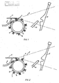
- the device (Fig. 1) consists of a body 1 of a rotary stripping brush 2 fitted with hairs 3 and with feed jets 4 .
- the rotary stripping brush 2 is situated under the lower strand of a shed 5 in whose grip is situated a weft 6 to be unravelled.
- the shed 5 is followed by a woven fabric 7 supported by a bar 8 .
- warp threads constituting the shed 5 pass through a reed 9 on which is located an auxiliary jet 10 .
- the first stage of the unravelling cycle consists in stopping the machine due to a signal coming from a sensor of a not represented stop motion and in loosening (releasing) the inserted, beaten-up, and separated weft 6 by the reverse motion of not represented heald shafts.
- the stripping brush 2 is displaced to its operative position shown in Fig. 1, i.e., under the lower strand of the open shed 5 next to the bar 8 supporting the woven fabric 7.
- the stripping brush receives rotary motion and, at the same time, pressure means are fed into the body 1 and begin to flow out through the feed jets 4 in a direction tangential to the surface of the body 1 of the rotary stripping brush 2 .
- Fig. 2 shows the second stage of the unravelling cycle in which the hairs 3 of the stripping brush 2 have freed the weft 6 to be unravelled from the grip of the shed 5 and have fed it to a certain distance from the interlacing point.
- the third stage of the unravelling cycle (Fig. 3) consists in that the hairs 3 of the stripping brush 2 are lowered under the lower strand of the shed 5 , and the weft 6 subject to unravelling is fed, by pressure means flowing out of the feed jets 4 , into the picking channel of the reed 9 . There, the weft 6 is exposed to the stream of pressure means flowing out of the auxiliary jets 10 , and thus displaced outside the shed 5 .
- the hairs 3 are situated on the body 1 of the stripping brush 2 in a helix.
Landscapes
- Engineering & Computer Science (AREA)
- Textile Engineering (AREA)
- Preliminary Treatment Of Fibers (AREA)
- Looms (AREA)
Abstract
Description
- The invention relates to a device for automatic removal of an inserted and beaten-up weft on weaving machines.
- A general aim common to all producers of weaving technique and appliances is to increase their useful performance. This aim can be reached in several ways, among them by minimizing the time required to repair weft defects, i.e., incorrectly inserted wefts. For this purpose, automatic devices for weft defect removal can be used.
- For removing the incorrectly inserted weft, many solutions are known. The most widely used has become a solution using the fact that the incorrectly inserted wefts remain connected with the supply on the metering member after the pick and beat-up have been carried out. In the following step, after a short reverse motion of the weaving machine and loosening of the incorrectly inserted weft from the interlacing by the warp threads, another weft, still connected with the incorrectly inserted weft, is picked to the shed end side. By pulling this weft, the incorrectly inserted weft is removed.
- Several drawbacks are inherent to this solution. It is, in the first place, the need to keep the incorrectly inserted weft in connection with the supply on the metering member, which imposes heavy demands on the reaction speed of the locking device preventing the inserted weft from being separated. Another important drawback consists in the fact that the described device fails to remove wefts that have suffered rupture during the pick so that one weft part is woven-in on the entering side, and the other part on the shed end side, of the weaving machine.
- To eliminate the drawbacks and imperfections of the known solutions is the aim of the device for automatic removal of the inserted and beaten-up wefts according to the present invention whose principle consists in that it is made of a rotary stripping brush with feed jets situated on the body of the rotary brush.
- The advantages of the device according to the present invention consist especially in that it is not necessary to ensure that the weft to be unravelled be not separated from the supply on the metering member, further in the possibility to remove also several (more than one) preceding wefts, and finally, that it permits to remove even wefts that suffered rupture during the machine operation. By dint of these advantages, the device marks a qualitatively higher degree as compared with the devices known up to now.
- Other advantages and features of the device according to the invention are described in the following description and shown in the accompanying drawings 1, 2 and 3, representing subsequent stages of the cycle for automatic weft removal.
- The device (Fig. 1) consists of a body 1 of a rotary stripping brush 2 fitted with hairs 3 and with feed jets 4. The rotary stripping brush 2 is situated under the lower strand of a shed 5 in whose grip is situated a weft 6 to be unravelled. The shed 5 is followed by a
woven fabric 7 supported by a bar 8. On the opposite side, warp threads constituting the shed 5 pass through a reed 9 on which is located anauxiliary jet 10. - The first stage of the unravelling cycle consists in stopping the machine due to a signal coming from a sensor of a not represented stop motion and in loosening (releasing) the inserted, beaten-up, and separated weft 6 by the reverse motion of not represented heald shafts.
- Then, the stripping brush 2 is displaced to its operative position shown in Fig. 1, i.e., under the lower strand of the open shed 5 next to the bar 8 supporting the
woven fabric 7. The stripping brush receives rotary motion and, at the same time, pressure means are fed into the body 1 and begin to flow out through the feed jets 4 in a direction tangential to the surface of the body 1 of the rotary stripping brush 2. - Fig. 2 shows the second stage of the unravelling cycle in which the hairs 3 of the stripping brush 2 have freed the weft 6 to be unravelled from the grip of the shed 5 and have fed it to a certain distance from the interlacing point.
- The third stage of the unravelling cycle (Fig. 3) consists in that the hairs 3 of the stripping brush 2 are lowered under the lower strand of the shed 5, and the weft 6 subject to unravelling is fed, by pressure means flowing out of the feed jets 4, into the picking channel of the reed 9. There, the weft 6 is exposed to the stream of pressure means flowing out of the
auxiliary jets 10, and thus displaced outside the shed 5. - For fluency and perfection of the loosening operation on the weft 6 to be unravelled, it is preferable to situate the hairs 3 on the body 1 of the stripping brush 2 in a helix.
Claims (5)
characterized by
a rotary stripping brush (2) with feed jets (4) situated on the body (1) of the rotary brush (2).
characterized in that
the rotary brush (2) is movably disposed under the lower strand of a shed (5) in whose grip is situated the weft (6) to be unravelled.
Applications Claiming Priority (2)
| Application Number | Priority Date | Filing Date | Title |
|---|---|---|---|
| CS5885/88 | 1988-09-01 | ||
| CS885885A CS275271B2 (en) | 1988-09-01 | 1988-09-01 | Device for choked and beaten-up weft removal on looms |
Publications (2)
| Publication Number | Publication Date |
|---|---|
| EP0356792A2 true EP0356792A2 (en) | 1990-03-07 |
| EP0356792A3 EP0356792A3 (en) | 1991-05-29 |
Family
ID=5404641
Family Applications (1)
| Application Number | Title | Priority Date | Filing Date |
|---|---|---|---|
| EP19890114905 Withdrawn EP0356792A3 (en) | 1988-09-01 | 1989-08-11 | A device for automatic removal of an inserted and beaten-up weft on weaving machines |
Country Status (3)
| Country | Link |
|---|---|
| US (1) | US5022440A (en) |
| EP (1) | EP0356792A3 (en) |
| CS (1) | CS275271B2 (en) |
Cited By (1)
| Publication number | Priority date | Publication date | Assignee | Title |
|---|---|---|---|---|
| DE3843399A1 (en) * | 1988-10-11 | 1990-04-12 | Dornier Gmbh Lindauer | AIR WOVENING MACHINE WITH A DEVICE FOR REMOVING A DEFECTIVE WIFE FROM THE WEAVING COMPARTMENT |
Families Citing this family (2)
| Publication number | Priority date | Publication date | Assignee | Title |
|---|---|---|---|---|
| FR2659361B1 (en) * | 1990-03-06 | 1994-07-29 | Saurer Diederichs Sa | AUTOMATIC DETACHING DEVICE FOR WEAVING MACHINES WITH MECHANICAL WEFT INSERTION. |
| US5390708A (en) * | 1993-09-21 | 1995-02-21 | Asten Group, Inc. | Apparatus for translating yarns in the proper position and orientation for forming a woven join |
Citations (3)
| Publication number | Priority date | Publication date | Assignee | Title |
|---|---|---|---|---|
| EP0100939A2 (en) * | 1982-07-21 | 1984-02-22 | Kabushiki Kaisha Toyoda Jidoshokki Seisakusho | Method for treating a weft yarn upon stoppage of a shuttleless loom and device for effecting the same |
| JPS59216956A (en) * | 1983-05-20 | 1984-12-07 | 株式会社豊田自動織機製作所 | Weft yarn treatment in shuttleless loom |
| EP0363705A1 (en) * | 1988-10-11 | 1990-04-18 | Lindauer Dornier Gesellschaft M.B.H | Air loom with a device for removing a faulty weft thread from the shed |
Family Cites Families (4)
| Publication number | Priority date | Publication date | Assignee | Title |
|---|---|---|---|---|
| US929734A (en) * | 1909-02-23 | 1909-08-03 | August Walder | Fluid-tight rotary joint for pipes. |
| US1199780A (en) * | 1915-10-20 | 1916-10-03 | Ralph B Goodrich | Rotary brush. |
| US1369567A (en) * | 1918-10-02 | 1921-02-22 | Mortimer L Smith | Rotary brush |
| US4490877A (en) * | 1983-11-20 | 1985-01-01 | Drumm Arthur E | Spiral brush section |
-
1988
- 1988-09-01 CS CS885885A patent/CS275271B2/en unknown
-
1989
- 1989-08-11 EP EP19890114905 patent/EP0356792A3/en not_active Withdrawn
- 1989-08-31 US US07/400,990 patent/US5022440A/en not_active Expired - Fee Related
Patent Citations (3)
| Publication number | Priority date | Publication date | Assignee | Title |
|---|---|---|---|---|
| EP0100939A2 (en) * | 1982-07-21 | 1984-02-22 | Kabushiki Kaisha Toyoda Jidoshokki Seisakusho | Method for treating a weft yarn upon stoppage of a shuttleless loom and device for effecting the same |
| JPS59216956A (en) * | 1983-05-20 | 1984-12-07 | 株式会社豊田自動織機製作所 | Weft yarn treatment in shuttleless loom |
| EP0363705A1 (en) * | 1988-10-11 | 1990-04-18 | Lindauer Dornier Gesellschaft M.B.H | Air loom with a device for removing a faulty weft thread from the shed |
Cited By (1)
| Publication number | Priority date | Publication date | Assignee | Title |
|---|---|---|---|---|
| DE3843399A1 (en) * | 1988-10-11 | 1990-04-12 | Dornier Gmbh Lindauer | AIR WOVENING MACHINE WITH A DEVICE FOR REMOVING A DEFECTIVE WIFE FROM THE WEAVING COMPARTMENT |
Also Published As
| Publication number | Publication date |
|---|---|
| CS8805885A1 (en) | 1990-12-13 |
| CS275271B2 (en) | 1992-02-19 |
| US5022440A (en) | 1991-06-11 |
| EP0356792A3 (en) | 1991-05-29 |
Similar Documents
| Publication | Publication Date | Title |
|---|---|---|
| US4502512A (en) | Method for treating a weft yarn upon stoppage of a shuttleless loom and device for effecting the same | |
| US4620570A (en) | Method and apparatus for disposal of weft yarn in a jet loom | |
| EP0354300A3 (en) | Weft treatment system and method for fluid jet loom | |
| US4759393A (en) | Loom | |
| EP0356792A2 (en) | A device for automatic removal of an inserted and beaten-up weft on weaving machines | |
| US4967803A (en) | Defective weft removal with unseparated weft lengths | |
| EP0344848B1 (en) | Method for threading jet nozzles of weaving machines with a correct length of the weft thread end, and a weaving machine which uses this method | |
| US5005609A (en) | Pneumatic removal of defective weft filament | |
| US4915144A (en) | Delivering yarns with an excess length from a yarn store in an air jet multicolor loom | |
| US4549582A (en) | Apparatus for removing severed fabric parts from a weaving machine | |
| US5090454A (en) | Deweaving apparatus with pneumatic defective pick release for shuttle-type loom | |
| JP2930739B2 (en) | Defective yarn removal method | |
| EP0322576A1 (en) | Method of releasing and mending wefts mispicked into the shed in jet weaving machines | |
| EP0318861A1 (en) | Method and device for removing a weft incorrectly inserted on a jet loom | |
| US5127445A (en) | Automatic gaiting arrangement for a fluid jet loom | |
| GB2119819A (en) | Device for receiving and checking the weft on a shuttle-less loom in which the weft is inserted pneumatically | |
| US5487413A (en) | Method for restarting the operation of an air jet loom, after defective weft removal | |
| US4890649A (en) | Faulty pick removal for a multiple-phase loom | |
| JPS6228446A (en) | Mistake yarn removing apparatus in jet loom | |
| JP2876321B2 (en) | Weft processing equipment for fluid jet loom | |
| US4821779A (en) | Method and apparatus for releasing defectively inserted weft threads in weaving machines | |
| EP0247691B1 (en) | Method for modelling a warp beam of weaving looms as well as method for carrying out the warp beam change and warp beam used to this end. | |
| US4640315A (en) | Projectile weaving machine | |
| JP3560332B2 (en) | Defective yarn removing method and defective yarn removing device | |
| JPH0635695B2 (en) | Weft processing method for shuttleless loom |
Legal Events
| Date | Code | Title | Description |
|---|---|---|---|
| PUAI | Public reference made under article 153(3) epc to a published international application that has entered the european phase |
Free format text: ORIGINAL CODE: 0009012 |
|
| AK | Designated contracting states |
Kind code of ref document: A2 Designated state(s): CH DE FR GB IT LI |
|
| PUAL | Search report despatched |
Free format text: ORIGINAL CODE: 0009013 |
|
| AK | Designated contracting states |
Kind code of ref document: A3 Designated state(s): CH DE FR GB IT LI |
|
| 17P | Request for examination filed |
Effective date: 19911121 |
|
| 17Q | First examination report despatched |
Effective date: 19930906 |
|
| STAA | Information on the status of an ep patent application or granted ep patent |
Free format text: STATUS: THE APPLICATION IS DEEMED TO BE WITHDRAWN |
|
| 18D | Application deemed to be withdrawn |
Effective date: 19940118 |