EP0356217B1 - A table to secure a pallet to support a workpiece on a machine tool - Google Patents
A table to secure a pallet to support a workpiece on a machine tool Download PDFInfo
- Publication number
- EP0356217B1 EP0356217B1 EP89308539A EP89308539A EP0356217B1 EP 0356217 B1 EP0356217 B1 EP 0356217B1 EP 89308539 A EP89308539 A EP 89308539A EP 89308539 A EP89308539 A EP 89308539A EP 0356217 B1 EP0356217 B1 EP 0356217B1
- Authority
- EP
- European Patent Office
- Prior art keywords
- spindle
- clamp
- pallet
- clamping
- spring
- Prior art date
- Legal status (The legal status is an assumption and is not a legal conclusion. Google has not performed a legal analysis and makes no representation as to the accuracy of the status listed.)
- Expired - Lifetime
Links
Images




Classifications
-
- B—PERFORMING OPERATIONS; TRANSPORTING
- B23—MACHINE TOOLS; METAL-WORKING NOT OTHERWISE PROVIDED FOR
- B23B—TURNING; BORING
- B23B31/00—Chucks; Expansion mandrels; Adaptations thereof for remote control
- B23B31/02—Chucks
- B23B31/10—Chucks characterised by the retaining or gripping devices or their immediate operating means
- B23B31/12—Chucks with simultaneously-acting jaws, whether or not also individually adjustable
- B23B31/18—Chucks with simultaneously-acting jaws, whether or not also individually adjustable pivotally movable in planes containing the axis of the chuck
-
- B—PERFORMING OPERATIONS; TRANSPORTING
- B23—MACHINE TOOLS; METAL-WORKING NOT OTHERWISE PROVIDED FOR
- B23Q—DETAILS, COMPONENTS, OR ACCESSORIES FOR MACHINE TOOLS, e.g. ARRANGEMENTS FOR COPYING OR CONTROLLING; MACHINE TOOLS IN GENERAL CHARACTERISED BY THE CONSTRUCTION OF PARTICULAR DETAILS OR COMPONENTS; COMBINATIONS OR ASSOCIATIONS OF METAL-WORKING MACHINES, NOT DIRECTED TO A PARTICULAR RESULT
- B23Q1/00—Members which are comprised in the general build-up of a form of machine, particularly relatively large fixed members
- B23Q1/0063—Connecting non-slidable parts of machine tools to each other
-
- Y—GENERAL TAGGING OF NEW TECHNOLOGICAL DEVELOPMENTS; GENERAL TAGGING OF CROSS-SECTIONAL TECHNOLOGIES SPANNING OVER SEVERAL SECTIONS OF THE IPC; TECHNICAL SUBJECTS COVERED BY FORMER USPC CROSS-REFERENCE ART COLLECTIONS [XRACs] AND DIGESTS
- Y10—TECHNICAL SUBJECTS COVERED BY FORMER USPC
- Y10T—TECHNICAL SUBJECTS COVERED BY FORMER US CLASSIFICATION
- Y10T29/00—Metal working
- Y10T29/51—Plural diverse manufacturing apparatus including means for metal shaping or assembling
- Y10T29/5196—Multiple station with conveyor
-
- Y—GENERAL TAGGING OF NEW TECHNOLOGICAL DEVELOPMENTS; GENERAL TAGGING OF CROSS-SECTIONAL TECHNOLOGIES SPANNING OVER SEVERAL SECTIONS OF THE IPC; TECHNICAL SUBJECTS COVERED BY FORMER USPC CROSS-REFERENCE ART COLLECTIONS [XRACs] AND DIGESTS
- Y10—TECHNICAL SUBJECTS COVERED BY FORMER USPC
- Y10T—TECHNICAL SUBJECTS COVERED BY FORMER US CLASSIFICATION
- Y10T409/00—Gear cutting, milling, or planing
- Y10T409/30—Milling
- Y10T409/30868—Work support
-
- Y—GENERAL TAGGING OF NEW TECHNOLOGICAL DEVELOPMENTS; GENERAL TAGGING OF CROSS-SECTIONAL TECHNOLOGIES SPANNING OVER SEVERAL SECTIONS OF THE IPC; TECHNICAL SUBJECTS COVERED BY FORMER USPC CROSS-REFERENCE ART COLLECTIONS [XRACs] AND DIGESTS
- Y10—TECHNICAL SUBJECTS COVERED BY FORMER USPC
- Y10T—TECHNICAL SUBJECTS COVERED BY FORMER US CLASSIFICATION
- Y10T74/00—Machine element or mechanism
- Y10T74/14—Rotary member or shaft indexing, e.g., tool or work turret
- Y10T74/1476—Rotary member or shaft indexing, e.g., tool or work turret with means to axially shift shaft
Definitions
- the invention relates generally to a table for use in association with machine tools, and more particularly to a table releasably to secure an automatic pallet supporting a workpiece on a machine tool.
- Tables have been previously proposed which clamp a pallet under hydraulic pressure.
- the employment of hydraulic pressure requires a hydraulic system.
- hydraulic systems have some disadvantages; one is that the size of the machine as a whole is increased. Another is that if a larger force acts on the pallet beyond the hydraulic clamping force, the pallet is likely to "float" or move.
- GB-A-2163979 It is known from GB-A-2163979 to produce such a table for securing a pallet to support a workpiece on a machine tool, the table comprising a spindle movable up and down, drive means to move the spindle in a vertical direction, a pair of retainers attached at an upper end of the spindle, a plurality of clamp arms arranged radially of the spindle, a clamp pawl formed integrally with an outer end of each clamp arm, with the clamp pawl being movable up and down and radially of the spindle, and a connecting member interposed between each clamp arm and an associated retainer.
- GB-A-2163979 relies on the presence of a pair of resiliently compressible washers to produce the clamping force.
- the clamping arms act on a pin which in turn acts on the washers. Since the clamping arms do not act directly on the washers or any other members which engage the pallet, there is a danger of forces produced in the pallet overcoming the clamping force which is occasioned primarily by the resistance of the washers.
- a table to secure a pallet to support a workpiece on a machine tool comprising a spindle movable up and down, drive means to move the spindle in a vertical direction, a pair of retainers attached at an upper end of the spindle, a plurality of clamp arms arranged radially of the spindle, a clamp pawl formed integrally with an outer end of each clamp arm, with the clamp pawl being movable up and down and radially of the spindle, and a connecting member interposed between each clamp arm and an associated retainer, characterised in that each connecting member has an end projection rotatably connected to an engaging recess of an associated clamp arm, and has a further end projection rotatably connected to an engaging recess of said associated retainer and in that the connecting members are such that they urge the associated clamp arms to move outwardly and upwardly to lock their clamp pawls at positions to clamp the pallet on the ascent of the spindle to cause the retainers to drive
- a table 1 is placed on a bed of a machine tool such as a machining centre such that the table 1 can move along guide rails 2 in a direction perpendicular to the plane of the paper of the drawing.
- the table 1 includes a space 3 to accommodate a clamp portion of a pallet P.
- the space 3 includes a lower opening 4 lined with a cylindrical wall member 6 clamped by bolts 7, and surrounded by a bottom plate 8 secured by bolts 9.
- a hydraulic chamber 10 is formed between the wall member 6 and the bottom plate 8. The hydraulic chamber 10 is supplied with fluid through a path 11.
- the space 3 is also provided with an index coupling 12 on its inside wall, and a vertically movable coupling 13 is disposed in such a manner as to be engageable with the stationary index coupling 12.
- the movable coupling 13 can be moved by a drive means (not shown) disposed adjacent an upper opening 5 of the table 1.
- a pallet base 15 is provided with a support block 16 in its lower section and a flange 17 in its upper section to support a clamping arm described below.
- the flange 17 is provided with face couplings 18 arranged in a circle on its top surface toward the pallet P.
- a cover 19 covers the upper opening 5 of the table 1.
- the support block 16 of the pallet base 15 is rotatable around the axis of the table 1 through bearings 20, and an index coupling 21 is fixed to the support block 16.
- the movable coupling 13 is engaged with the index coupling 21 and the index coupling 12 of the table 1, thereby enabling the pallet base 15 to be held fast at a desired indexed position.
- a hydraulic cylinder 22 has a flange portion 23 bolted to the bottom of the pallet base 15 with its lower end extending through the bottom plate 8 of the table 1 and with its lower periphery sealed against the inside wall of the bottom plate 8 through a seal ring 24.
- the hydraulic cylinder 22 includes an annular step 25, and a hydraulic chamber 27 between the annular step 25 and a bottom member 26, the hydraulic chamber 27 being supplied with fluid through paths 28 and 29.
- the hydraulic cylinder 22 includes slots 30 in its upper section, the slots 30 being diametrically opposed to each other and axially extending.
- a spindle 31 is movably inserted in the hydraulic cylinder 22 in contact with the inside wall of the ring-shaped step 25.
- the spindle 31 is fitted with another spindle 32 which moves in the hydraulic chamber 27.
- the spindle 31 has a pair of blocks 33, 34 mounted thereon separated by springs 35.
- the structure and function of the blocks 33, 34 will be described below:
- the spindle 31 includes a bore 36 in which a spring 37 is inserted to urge the spindle 31 upward from its support by the bottom plate 26.
- a cylindrical piston 40 is fitted around a lower part of the hydraulic cylinder 22 so as to release the clamping pressure.
- the piston 40 includes a lower portion 41 and an upper ring-shaped shoulder 42.
- the lower portion 41 moves in the hydraulic chamber 10.
- the piston 40 is normally biased upward by a spring 43 disposed between the lower portion 41 and the bottom plate 8.
- a pallet clamping ring 50 of cylindrical form is fitted around an upper part of the cylinder 22 above its flange portion 23.
- the clamping ring 50 as shown in Figure 6, includes four slots 51 cut downward from its rim, the four slots 51 being spaced at angular intervals of 90°, and four T-shaped grooves 52 which are also spaced at angular intervals of 90°.
- the T-shaped grooves 52 are each positioned between a respective adjacent pair of the slots 51.
- a pair of holes 53 is provided diametrically located, below two of the slots 51. The holes 53 allow pins 61 to pass through.
- clamping ring 50 is notionally split into four wall components 54 between each adjacent pair of the slots 51.
- Each wall component 54 is provided with a sector-shaped member 55 shown in Figure 7 fixed by means of bolts 56, as shown in Figure 4 and 5.
- Each sector-shaped member 55 includes holes 58 to allow guide posts 59 to pass therethrough and threaded holes 57 to receive the fastening bolts 56.
- the clamping ring 50 equipped with the sector-shaped members 55 is slidably fitted around the hydraulic cylinder 22. As best shown in Figure 5, the spring guide posts 59 are erected on the bottom of the pallet base 15 and pass through the holes 58. The clamping ring 50 is biased upward by springs 60 located on the spring guide posts 59.
- the pins 61 pass through the holes 53 such that heads 62 thereof protrude inside the clamping ring 50 and engage in the slots 30 of the hydraulic cylinder 22. In this way the clamping ring 50 is allowed to move vertically within the range limited by the slots 30.
- An unclamping pin 63 is fixed to a lower part of the clamping ring 50. As shown in Figure 8, the unclamping pin 63 includes a head 65, a neck 64 and a leg 66. Each unclamping pin 63 is fixed to the clamping ring 50 by inserting the head 65 and the neck 64 in one of the T-shaped grooves 52 ( Figure 6). Each clamping pin 63 passes through a hole 67 in the cylinder 22 and extends downwardly until its leg 66 engages the upper annular shoulder 42 of the piston 40.
- a movable engager 70 includes pawls 71 and 72 at opposite ends and a pivotal dowel 73 at its centre.
- the dowel 73 engages in a recess 74 in the head 62 of the pin 61 so that the engager 70 can oscillate about the dowel 73.
- the blocks 33, 34 are each shaped in the form of eight-sided figure as shown in Figure 9, and respectively include horn members 78 and 79 diametrically arranged. Each horn member 78, 79 includes a semi-circular recess 77. Though the two blocks 33 and 34 are of similar form, they are different in their fixing position with respect to the respective body portions such that when the blocks 33 and 34 are joined face to face, the horn members 78 and 79 are in the same plane and angularly spaced by 90°.
- the facially joined blocks 33, 34 are fixed on the top end of the spindle 31 and separated by the spring 35.
- the blocks 33 and 34 are maintained by bolts 81 through a presser plate 80 in such a manner as to be movable under the action of the spring 35.
- the movability of the blocks 33, 34 equalizes the clamping pressure by a plurality of clamp arms 85, which will be hereinafter described in greater detail.
- the pressure of the spring 35 is arranged to be smaller than that of the springs 60 which urge the clamping ring 50 upward.
- each clamp arm 85 is generally of the form of a letter J, and includes a hook-like clamping pawl 86, an engaging recess 87 at the back of the pawl 86, and an engager 88.
- the clamp arms 85 are accommodated in an annular recess 89 formed between the pallet base 15 and the clamping ring 50, and located at places corresponding to the horn members 78 and 79. Each clamp arm 85 is supported by the sector-shaped members 55 at both sides and its engager 88 is held in engagement with the flange 17.
- Each clamp arm 85 and the respective horn member 78 or 79 are connected by a connecting member 90 which includes end projections 91 and 92 of a semi-circular cross-section.
- the projection 91 is engaged with the recess 87 of the clamp arm 85
- the other projection 92 is engaged with the recess 77 of the horn member 78 or 79.
- the clamp arms 85 are rotatably connected to the blocks 33, 34 through the connecting members 90.
- the connecting member 90 prevents the clamp arms 85 from moving to the unclamping position, and locks the clamp arms 85 to the clamping positions.
- the clamp unit is covered by a cover 93 which is supported by a vertically movable pin 94 and wholly covers the pallet base 15 in the unclamping condition.
- the pallet P is fastened by a fastening ring 95 which is fixed to the bottom plate of the pallet P by bolts 96 and is provided with face couplings 97 engageable with the face couplings 18 of the pallet base 15.
- the fastening ring 95 is also provided with an annular step 98.
- the table 1 is operated as follows: In the position of Figure 1 the pallet P placed on the pallet base 15 is prevented from turning because of its coupling 97 being engaged with the face coupling 18. At this stage the pallet P is clamped by the pawls 86 of the clamp arms 85 which are engaged with the step 98. At a position where the pallet P is clamped the clamp arms 85 are maintained by the connecting members 90 which are biased upward by the springs 37 and 60. While the clamp arms 85 are maintained at the clamping position, a strong clamping force is imparted to the arms 85 to guarantee that the pallet P retains its clamped state irrespective of an unexpected external force.
- Fluid is introduced into the hydraulic chamber 10 through the path 11 from a source (not shown), whereby the piston 40 is forced downward against the force of the spring 43.
- the unclamping pins 63 and the pallet clamp ring 50 are caused to descend against the force of the springs 60.
- the descent of the clamp ring 50 causes the movable engagers 70 to descend due to the pins 60, thereby releasing the lower pawls 71 from the step 75 of the spindle 31, and bringing the upper pawls 72 into abutment with an upper slanted part of the cylinder 22.
- the cover 93 closes the opening of the pallet base 15. As the repositioning or replacement of the pallet P takes place, the cover 93 and the cover 19 prevent cutting chips and used oil from intruding into the inside of the table 1.
Landscapes
- Engineering & Computer Science (AREA)
- Mechanical Engineering (AREA)
- Jigs For Machine Tools (AREA)
- Machine Tool Positioning Apparatuses (AREA)
- Feeding Of Workpieces (AREA)
Description
- The invention relates generally to a table for use in association with machine tools, and more particularly to a table releasably to secure an automatic pallet supporting a workpiece on a machine tool.
- Tables have been previously proposed which clamp a pallet under hydraulic pressure. The employment of hydraulic pressure requires a hydraulic system. However, hydraulic systems have some disadvantages; one is that the size of the machine as a whole is increased. Another is that if a larger force acts on the pallet beyond the hydraulic clamping force, the pallet is likely to "float" or move.
- It is known from GB-A-2163979 to produce such a table for securing a pallet to support a workpiece on a machine tool, the table comprising a spindle movable up and down, drive means to move the spindle in a vertical direction, a pair of retainers attached at an upper end of the spindle, a plurality of clamp arms arranged radially of the spindle, a clamp pawl formed integrally with an outer end of each clamp arm, with the clamp pawl being movable up and down and radially of the spindle, and a connecting member interposed between each clamp arm and an associated retainer. However, the arrangement of GB-A-2163979 relies on the presence of a pair of resiliently compressible washers to produce the clamping force. The clamping arms act on a pin which in turn acts on the washers. Since the clamping arms do not act directly on the washers or any other members which engage the pallet, there is a danger of forces produced in the pallet overcoming the clamping force which is occasioned primarily by the resistance of the washers.
- According to the invention, there is provided a table to secure a pallet to support a workpiece on a machine tool, the table comprising a spindle movable up and down, drive means to move the spindle in a vertical direction, a pair of retainers attached at an upper end of the spindle, a plurality of clamp arms arranged radially of the spindle, a clamp pawl formed integrally with an outer end of each clamp arm, with the clamp pawl being movable up and down and radially of the spindle, and a connecting member interposed between each clamp arm and an associated retainer, characterised in that each connecting member has an end projection rotatably connected to an engaging recess of an associated clamp arm, and has a further end projection rotatably connected to an engaging recess of said associated retainer and in that the connecting members are such that they urge the associated clamp arms to move outwardly and upwardly to lock their clamp pawls at positions to clamp the pallet on the ascent of the spindle to cause the retainers to drive the connecting members, descent of the spindle causing the retainers to retract the connecting members so that they urge the associated clamp arms to move inwardly and downwardly to return the clamp pawls to their original positions to unclamp the pallet.
- The invention is diagrammatically illustrated by way of example in the accompanying drawings, in which:-
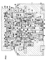
- Figure 1 is a cross-sectional front view showing a table according to the invention with a pallet clamped by the table;
- Figure 2 is a cross-sectional front view showing the table of Figure 1 with the clamping pressure released;
- Figure 3 is a cross-sectional front view showing the table of Figure 1 in its unclamped state;
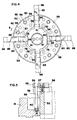
- Figure 4 is a cross-sectional view taken on line 4-4 in Figure 1;
- Figure 5 is a cross-sectional view taken on line 5-5 in Figure 4;
- Figure 6 is a perspective view showing a pallet clamping ring of the table of Figure 1;
- Figure 7 is a perspective view showing a sector-shaped member of the table of Figure 1;
- Figure 8 is a perspective view showing an unclamping pin of the table of Figure 1;
- Figure 9 is a perspective view showing an arm pressing block of the table of Figure 1;
- Figure 10 is a perspective view showing a clamping arm of the table of Figure 1; and
- Figure 11 is a perspective view showing a connecting member of the table of Figure 1.
- Referring to Figure 1, a table 1 is placed on a bed of a machine tool such as a machining centre such that the table 1 can move along
guide rails 2 in a direction perpendicular to the plane of the paper of the drawing. - The table 1 includes a
space 3 to accommodate a clamp portion of a pallet P. Thespace 3 includes a lower opening 4 lined with a cylindrical wall member 6 clamped by bolts 7, and surrounded by abottom plate 8 secured bybolts 9. Ahydraulic chamber 10 is formed between the wall member 6 and thebottom plate 8. Thehydraulic chamber 10 is supplied with fluid through a path 11. - The
space 3 is also provided with anindex coupling 12 on its inside wall, and a verticallymovable coupling 13 is disposed in such a manner as to be engageable with thestationary index coupling 12. Themovable coupling 13 can be moved by a drive means (not shown) disposed adjacent an upper opening 5 of the table 1. - A
pallet base 15 is provided with asupport block 16 in its lower section and aflange 17 in its upper section to support a clamping arm described below. Theflange 17 is provided withface couplings 18 arranged in a circle on its top surface toward the pallet P. Acover 19 covers the upper opening 5 of the table 1. - The
support block 16 of thepallet base 15 is rotatable around the axis of the table 1 throughbearings 20, and anindex coupling 21 is fixed to thesupport block 16. Themovable coupling 13 is engaged with theindex coupling 21 and theindex coupling 12 of the table 1, thereby enabling thepallet base 15 to be held fast at a desired indexed position. - A
hydraulic cylinder 22 has a flange portion 23 bolted to the bottom of thepallet base 15 with its lower end extending through thebottom plate 8 of the table 1 and with its lower periphery sealed against the inside wall of thebottom plate 8 through aseal ring 24. - The
hydraulic cylinder 22 includes anannular step 25, and ahydraulic chamber 27 between theannular step 25 and abottom member 26, thehydraulic chamber 27 being supplied with fluid throughpaths - The
hydraulic cylinder 22 includes slots 30 in its upper section, the slots 30 being diametrically opposed to each other and axially extending. - A
spindle 31 is movably inserted in thehydraulic cylinder 22 in contact with the inside wall of the ring-shaped step 25. Thespindle 31 is fitted with anotherspindle 32 which moves in thehydraulic chamber 27. - The
spindle 31 has a pair ofblocks springs 35. The structure and function of theblocks
Thespindle 31 includes abore 36 in which a spring 37 is inserted to urge thespindle 31 upward from its support by thebottom plate 26. - A
cylindrical piston 40 is fitted around a lower part of thehydraulic cylinder 22 so as to release the clamping pressure. Thepiston 40 includes alower portion 41 and an upper ring-shaped shoulder 42. Thelower portion 41 moves in thehydraulic chamber 10. Thepiston 40 is normally biased upward by aspring 43 disposed between thelower portion 41 and thebottom plate 8. - A
pallet clamping ring 50 of cylindrical form is fitted around an upper part of thecylinder 22 above its flange portion 23. - The
clamping ring 50, as shown in Figure 6, includes fourslots 51 cut downward from its rim, the fourslots 51 being spaced at angular intervals of 90°, and four T-shaped grooves 52 which are also spaced at angular intervals of 90°. The T-shaped grooves 52 are each positioned between a respective adjacent pair of theslots 51. A pair ofholes 53 is provided diametrically located, below two of theslots 51. Theholes 53 allow pins 61 to pass through. - In this way the
clamping ring 50 is notionally split into fourwall components 54 between each adjacent pair of theslots 51. Eachwall component 54 is provided with a sector-shaped member 55 shown in Figure 7 fixed by means ofbolts 56, as shown in Figure 4 and 5. - Each sector-
shaped member 55 includesholes 58 to allowguide posts 59 to pass therethrough and threadedholes 57 to receive thefastening bolts 56. - The
clamping ring 50 equipped with the sector-shaped members 55 is slidably fitted around thehydraulic cylinder 22. As best shown in Figure 5, thespring guide posts 59 are erected on the bottom of thepallet base 15 and pass through theholes 58. Theclamping ring 50 is biased upward bysprings 60 located on thespring guide posts 59. - The pins 61 pass through the
holes 53 such that heads 62 thereof protrude inside theclamping ring 50 and engage in the slots 30 of thehydraulic cylinder 22. In this way theclamping ring 50 is allowed to move vertically within the range limited by the slots 30. - An
unclamping pin 63 is fixed to a lower part of theclamping ring 50. As shown in Figure 8, theunclamping pin 63 includes ahead 65, aneck 64 and aleg 66. Eachunclamping pin 63 is fixed to theclamping ring 50 by inserting thehead 65 and theneck 64 in one of the T-shaped grooves 52 (Figure 6). Eachclamping pin 63 passes through ahole 67 in thecylinder 22 and extends downwardly until itsleg 66 engages the upperannular shoulder 42 of thepiston 40. - A
movable engager 70 includes pawls 71 and 72 at opposite ends and a pivotal dowel 73 at its centre. The dowel 73 engages in a recess 74 in the head 62 of the pin 61 so that the engager 70 can oscillate about the dowel 73. When theclamping ring 50 is at a higher position, as shown in Figure 1, the lower pawl 71 is engaged with a step 75 on the outside wall of thespindle 31. When the clampingring 50 is at a lower position, as shown in Figures 2 and 3, the upper pawl 72 comes into abutment with a slanted surface of thehydraulic cylinder 22, and is displaced inwardly. As a result, the lower pawl 71 is displaced outwardly and accommodated in a recess 76 in the inside wall of thehydraulic cylinder 22. - The
blocks horn members horn member semi-circular recess 77. Though the twoblocks blocks horn members blocks spindle 31 and separated by thespring 35. Theblocks bolts 81 through apresser plate 80 in such a manner as to be movable under the action of thespring 35. The movability of theblocks clamp arms 85, which will be hereinafter described in greater detail. The pressure of thespring 35 is arranged to be smaller than that of thesprings 60 which urge the clampingring 50 upward. - As shown in Figure 10 each
clamp arm 85 is generally of the form of a letter J, and includes a hook-like clamping pawl 86, an engagingrecess 87 at the back of thepawl 86, and anengager 88. - The
clamp arms 85 are accommodated in anannular recess 89 formed between thepallet base 15 and the clampingring 50, and located at places corresponding to thehorn members clamp arm 85 is supported by the sector-shapedmembers 55 at both sides and itsengager 88 is held in engagement with theflange 17. - Each
clamp arm 85 and therespective horn member member 90 which includesend projections projection 91 is engaged with therecess 87 of theclamp arm 85, and theother projection 92 is engaged with therecess 77 of thehorn member clamp arms 85 are rotatably connected to theblocks members 90. In the clamping condition shown in Figure 1 the connectingmember 90 prevents theclamp arms 85 from moving to the unclamping position, and locks theclamp arms 85 to the clamping positions. - The clamp unit is covered by a
cover 93 which is supported by a verticallymovable pin 94 and wholly covers thepallet base 15 in the unclamping condition. - The pallet P is fastened by a
fastening ring 95 which is fixed to the bottom plate of the pallet P bybolts 96 and is provided withface couplings 97 engageable with theface couplings 18 of thepallet base 15. Thefastening ring 95 is also provided with anannular step 98. - The table 1 is operated as follows:
In the position of Figure 1 the pallet P placed on thepallet base 15 is prevented from turning because of itscoupling 97 being engaged with theface coupling 18. At this stage the pallet P is clamped by thepawls 86 of theclamp arms 85 which are engaged with thestep 98. At a position where the pallet P is clamped theclamp arms 85 are maintained by the connectingmembers 90 which are biased upward by thesprings 37 and 60. While theclamp arms 85 are maintained at the clamping position, a strong clamping force is imparted to thearms 85 to guarantee that the pallet P retains its clamped state irrespective of an unexpected external force. - When the clamped pallet P is to be released or unclamped, the clamping force imparted by the
springs 60 is released. - Fluid is introduced into the
hydraulic chamber 10 through the path 11 from a source (not shown), whereby thepiston 40 is forced downward against the force of thespring 43. In accordance with the downward movement of thepiston 40 the unclamping pins 63 and thepallet clamp ring 50 are caused to descend against the force of thesprings 60. The descent of theclamp ring 50 causes themovable engagers 70 to descend due to thepins 60, thereby releasing the lower pawls 71 from the step 75 of thespindle 31, and bringing the upper pawls 72 into abutment with an upper slanted part of thecylinder 22. In this way the upper pawls 72 are displaced inwardly whereas the lower pawls 71 are displaced outwardly and accommodated in the recess 76. When the pawls 71 of themovable engagers 70 are disengaged from the step 75 of thespindle 31, thespindle 31 is released from the force provided by thesprings 60, and the clamping force on theclamp arms 85 is also lost but they retain their clamping position under the action of the spring 37. This is the position shown in Figure 2. - Then, fluid is introduced into the
hydraulic chamber 27 through thepaths table spindle 31 is caused to descend against the spring 37. In accordance with the descent of thespindle 31 theblocks members 90 to descend. In this way theclamp arms 85 are drawn radially inwardly, thereby enabling thepawls 86 to move to the unclamping position where they are separated from thestep 98 of the pallet P. The pallet P is thus freed for repositioning. - At the unclamping position the
cover 93 closes the opening of thepallet base 15. As the repositioning or replacement of the pallet P takes place, thecover 93 and thecover 19 prevent cutting chips and used oil from intruding into the inside of the table 1. - When a fresh pallet P is to be clamped, the procedure is followed in reverse. First, the oil in the
hydraulic chamber 27 is discharged, thereby allowing thespindle 31 to rise up due to the spring 37, and moving theclamp arms 85 to the clamping positions. Then, the fluid in thechamber 10 is discharged, thereby allowing thepiston 40 to return to the position shown in Figure 1 due to thespring 43. Simultaneously, the clampingpin 50 and theunclamping pin 63 are raised to the position shown in Figure 1 by thespring 60 through the sector-shapedmembers 55. As they rise, the lower pawls 71 of themovable engagers 70 are engaged with the step 75 of thespindle 31. In this way the raising force is imparted to thespindle 31. The raising force is transmitted to theclamp arms 85 through theblocks members 90. Thus thepawls 86 have their clamping force restored.
Claims (4)
- A table to secure a pallet to support a workpiece on a machine tool, the table (1) comprising a spindle (31) movable up and down, drive means to move the spindle in a vertical direction, a pair of retainers (33, 34) attached at an upper end of the spindle, a plurality of clamp arms (85) arranged radially of the spindle (31), a clamp pawl (86) formed integrally with an outer end of each clamp arm (85), with the clamp pawl (86) being movable up and down and radially of the spindle (31), and a connecting member (90) interposed between each clamp arm (85) and an associated retainer (33, 34) characterised in that each connecting member (90) has an end projection (91) rotatably connected to an engaging recess (87) of an associated clamp arm (85), and has a further end projection (92) rotatably connected to an engaging recess (77) of said associated retainer (33, 34); and in that the connecting members (90) are such that they urge the associated clamp arms (85) to move outwardly and upwardly to lock their clamp pawls (86) at positions to clamp the pallet (P) on the ascent of the spindle (31) to cause the retainers (33, 34) to drive the connecting members (90), descent of the spindle causing the retainers (33, 34) to retract the connecting members (90) so that they urge the associated clamp arms (85) to move inwardly and downwardly to return the clamp pawls (86) to their original positions to unclamp the pallet (P).
- A table according to claim 1, wherein the arm operating means comprises springs (37, 60) to raise the spindle (31) upward, and hydraulic means to force down the spindle (31) against the springs.
- A table according to claim 2, wherein the springs (37, 60) comprise a first spring (37) to raise the clamp arms (85) to a position where the pallet (P) is clamped, and a second spring (60) to impart a clamping force to the clamp arms positioned at the clamping position, and wherein the hydraulic means comprises a first hydraulic means to force down the spindle against the first spring (37), and second hydraulic means to cause the second spring to release the clamping force upon the clamp arms.
- A table according to any one of claims 1 to 3, including a cover (93) placed above the spindle (31), thereby covering the table (1) so as to protect the clamping unit against dust and oil when the spindle (31) descends.
Applications Claiming Priority (2)
| Application Number | Priority Date | Filing Date | Title |
|---|---|---|---|
| JP209170/88 | 1988-08-23 | ||
| JP63209170A JP2906058B2 (en) | 1988-08-23 | 1988-08-23 | Machine tool table equipment |
Publications (3)
| Publication Number | Publication Date |
|---|---|
| EP0356217A2 EP0356217A2 (en) | 1990-02-28 |
| EP0356217A3 EP0356217A3 (en) | 1992-05-20 |
| EP0356217B1 true EP0356217B1 (en) | 1994-06-22 |
Family
ID=16568491
Family Applications (1)
| Application Number | Title | Priority Date | Filing Date |
|---|---|---|---|
| EP89308539A Expired - Lifetime EP0356217B1 (en) | 1988-08-23 | 1989-08-23 | A table to secure a pallet to support a workpiece on a machine tool |
Country Status (4)
| Country | Link |
|---|---|
| US (1) | US5133538A (en) |
| EP (1) | EP0356217B1 (en) |
| JP (1) | JP2906058B2 (en) |
| DE (1) | DE68916336T2 (en) |
Families Citing this family (13)
| Publication number | Priority date | Publication date | Assignee | Title |
|---|---|---|---|---|
| DE4122215C2 (en) * | 1991-07-04 | 1999-02-11 | Deckel Maho Gmbh | Automatic pallet changing device |
| DE4136796C2 (en) * | 1991-11-08 | 1994-03-03 | Georg Fellner | Quick clamping device for tools of hot forging presses |
| DE4314629C2 (en) * | 1993-05-04 | 1995-10-19 | Erowa Ag | Device for the position-defined clamping of a workpiece at the workplace of a processing machine |
| JP2756644B2 (en) * | 1994-05-26 | 1998-05-25 | ソーコー株式会社 | Construction method of artificial turf stadium |
| DE19716797A1 (en) * | 1997-04-22 | 1998-11-05 | Emil Stark | Correct one-nipple clamping |
| US5904348A (en) * | 1997-06-03 | 1999-05-18 | Chrysler Corporation | Body-locking holddown device |
| DE19806961A1 (en) * | 1998-02-19 | 1999-08-26 | Emil Stark | Quick-release cylinder for pulling in and centering a pull-in nipple |
| DE10061524C2 (en) * | 2000-12-09 | 2003-02-06 | Werkzeugmaschfab Vogtland Veb | Rotary indexing device for use in a group of processing stations |
| JP5152896B2 (en) * | 2007-10-10 | 2013-02-27 | 津田駒工業株式会社 | Rotary indexing device in machine tools |
| US8770065B2 (en) * | 2009-11-05 | 2014-07-08 | Colonial Tool Group Inc. | Rotary workpiece indexing method and apparatus |
| CN103302514B (en) * | 2013-05-21 | 2015-11-04 | 太仓市天合新材料科技有限公司 | A kind of elastic wire automatic fixture |
| JP6370767B2 (en) * | 2015-11-25 | 2018-08-08 | ファナック株式会社 | Rotary table device for electric discharge machine |
| CN109551199B (en) * | 2019-01-15 | 2024-04-26 | 苏州天准科技股份有限公司 | Servo press fitting floating self-locking supporting mechanism |
Family Cites Families (13)
| Publication number | Priority date | Publication date | Assignee | Title |
|---|---|---|---|---|
| US2672675A (en) * | 1950-02-04 | 1954-03-23 | Ralph E Cross | Locating and clamping mechanism |
| US2955347A (en) * | 1956-07-09 | 1960-10-11 | Buhr Machine Tool Company | Pallet clamp construction |
| US3082015A (en) * | 1961-11-28 | 1963-03-19 | Woodworth Co N A | Equalizing chuck |
| GB1308563A (en) * | 1969-06-21 | 1973-02-21 | Olivetti & Co Spa | Machine tool with rotary work-table |
| US4032163A (en) * | 1976-01-26 | 1977-06-28 | Holt Donald G | Quick change in-motion tool chuck |
| US4015487A (en) * | 1976-02-23 | 1977-04-05 | Cincinnati Milacron, Inc. | Index mechanism |
| DD145236A1 (en) * | 1979-08-03 | 1980-12-03 | Horst Geissler | DEVICE FOR REPLACING MODEL PLATES |
| JPS5851835U (en) * | 1981-10-05 | 1983-04-08 | 相生精機株式会社 | Clamper of processing machine |
| SE440618B (en) * | 1983-04-12 | 1985-08-12 | Schedwin Sven Erik | FIXED TENSION DEVICE, IN PARTICULAR FOR FIXED TENSION OF WORKBOARDS, FIXTURES OR SIMILAR ON A SUBSTRATE, LIKE THE MACHINE TABLE IN A WORKING MACHINE |
| US4575062A (en) * | 1984-09-05 | 1986-03-11 | American Machine & Science, Inc. | Coupling construction and clamp therefor |
| US4662043A (en) * | 1985-01-10 | 1987-05-05 | Sheffer Collet Company | Project plate system |
| DD250828A3 (en) * | 1985-07-31 | 1987-10-28 | Werkzeugmasch Forschzent | MOUNTING DEVICE ON A TOOL MACHINE |
| SE466090B (en) * | 1987-05-07 | 1991-12-16 | 3R Syst Int Ab | DEVICE FOR RELIABLE AND REPEATABLE TENSION OF TWO OBJECTS ON EACH OTHER |
-
1988
- 1988-08-23 JP JP63209170A patent/JP2906058B2/en not_active Expired - Fee Related
-
1989
- 1989-08-22 US US07/397,129 patent/US5133538A/en not_active Expired - Lifetime
- 1989-08-23 EP EP89308539A patent/EP0356217B1/en not_active Expired - Lifetime
- 1989-08-23 DE DE68916336T patent/DE68916336T2/en not_active Expired - Fee Related
Also Published As
| Publication number | Publication date |
|---|---|
| JPH0259242A (en) | 1990-02-28 |
| JP2906058B2 (en) | 1999-06-14 |
| EP0356217A2 (en) | 1990-02-28 |
| DE68916336T2 (en) | 1994-10-13 |
| DE68916336D1 (en) | 1994-07-28 |
| US5133538A (en) | 1992-07-28 |
| EP0356217A3 (en) | 1992-05-20 |
Similar Documents
| Publication | Publication Date | Title |
|---|---|---|
| EP1078713B1 (en) | Clamping apparatus with datum function | |
| EP0356217A2 (en) | A table to secure a pallet to support a workpiece on a machine tool | |
| AU769635B2 (en) | An apparatus for clamping a work piece | |
| EP1264658B1 (en) | Clamping apparatus with datum function | |
| US6988720B2 (en) | Clamping device | |
| EP2489464B1 (en) | Clamp device | |
| US5848563A (en) | Multiple tool for punch press | |
| US6641127B2 (en) | Clamping apparatus | |
| EP1552901B1 (en) | Clamp device | |
| EP1666197B1 (en) | Clamp device | |
| US20060049568A1 (en) | Aligning drive mechanism and positioning apparatus having this mechanism | |
| EP1338374B2 (en) | Device for automatically positioning a movable member onto a reference member | |
| CA1265825A (en) | Cooperating bolster and fixture construction for quick-change fixturing | |
| JPH03202243A (en) | Clamping tool turning and direct-acting type hydraulic clamp | |
| EP1649973B1 (en) | Clamp device | |
| US4443141A (en) | Pinless pressure foot for machine tool | |
| US4179106A (en) | Apparatus for locating and clamping a work member supporting fixture | |
| EP0636450B1 (en) | Clamping apparatus | |
| EP0228201B1 (en) | Hand-operated pallet changer | |
| KR101345024B1 (en) | Check device of spindle tool clamp for machine tool | |
| US3978767A (en) | Automatic center holding fixture for an annular workpiece | |
| JPS6179538A (en) | Automatic tool exchanger device of vertical machining center | |
| US4602797A (en) | Tandem chuck | |
| JPH0746433Y2 (en) | Pallet clamp device | |
| JPH048446A (en) | Gripper device for cutter |
Legal Events
| Date | Code | Title | Description |
|---|---|---|---|
| PUAI | Public reference made under article 153(3) epc to a published international application that has entered the european phase |
Free format text: ORIGINAL CODE: 0009012 |
|
| AK | Designated contracting states |
Kind code of ref document: A2 Designated state(s): CH DE FR GB IT LI |
|
| PUAL | Search report despatched |
Free format text: ORIGINAL CODE: 0009013 |
|
| AK | Designated contracting states |
Kind code of ref document: A3 Designated state(s): CH DE FR GB IT LI |
|
| 17P | Request for examination filed |
Effective date: 19921029 |
|
| 17Q | First examination report despatched |
Effective date: 19930120 |
|
| GRAA | (expected) grant |
Free format text: ORIGINAL CODE: 0009210 |
|
| AK | Designated contracting states |
Kind code of ref document: B1 Designated state(s): CH DE FR GB IT LI |
|
| ITF | It: translation for a ep patent filed | ||
| REF | Corresponds to: |
Ref document number: 68916336 Country of ref document: DE Date of ref document: 19940728 |
|
| ET | Fr: translation filed | ||
| PLBE | No opposition filed within time limit |
Free format text: ORIGINAL CODE: 0009261 |
|
| STAA | Information on the status of an ep patent application or granted ep patent |
Free format text: STATUS: NO OPPOSITION FILED WITHIN TIME LIMIT |
|
| 26N | No opposition filed | ||
| REG | Reference to a national code |
Ref country code: GB Ref legal event code: IF02 |
|
| PGFP | Annual fee paid to national office [announced via postgrant information from national office to epo] |
Ref country code: FR Payment date: 20030808 Year of fee payment: 15 |
|
| PGFP | Annual fee paid to national office [announced via postgrant information from national office to epo] |
Ref country code: GB Payment date: 20030820 Year of fee payment: 15 |
|
| PGFP | Annual fee paid to national office [announced via postgrant information from national office to epo] |
Ref country code: CH Payment date: 20030829 Year of fee payment: 15 |
|
| PG25 | Lapsed in a contracting state [announced via postgrant information from national office to epo] |
Ref country code: GB Free format text: LAPSE BECAUSE OF NON-PAYMENT OF DUE FEES Effective date: 20040823 |
|
| PG25 | Lapsed in a contracting state [announced via postgrant information from national office to epo] |
Ref country code: LI Free format text: LAPSE BECAUSE OF NON-PAYMENT OF DUE FEES Effective date: 20040831 Ref country code: CH Free format text: LAPSE BECAUSE OF NON-PAYMENT OF DUE FEES Effective date: 20040831 |
|
| PGFP | Annual fee paid to national office [announced via postgrant information from national office to epo] |
Ref country code: DE Payment date: 20040902 Year of fee payment: 16 |
|
| GBPC | Gb: european patent ceased through non-payment of renewal fee |
Effective date: 20040823 |
|
| REG | Reference to a national code |
Ref country code: CH Ref legal event code: PL |
|
| PG25 | Lapsed in a contracting state [announced via postgrant information from national office to epo] |
Ref country code: FR Free format text: LAPSE BECAUSE OF NON-PAYMENT OF DUE FEES Effective date: 20050429 |
|
| REG | Reference to a national code |
Ref country code: FR Ref legal event code: ST |
|
| PG25 | Lapsed in a contracting state [announced via postgrant information from national office to epo] |
Ref country code: IT Free format text: LAPSE BECAUSE OF NON-PAYMENT OF DUE FEES;WARNING: LAPSES OF ITALIAN PATENTS WITH EFFECTIVE DATE BEFORE 2007 MAY HAVE OCCURRED AT ANY TIME BEFORE 2007. THE CORRECT EFFECTIVE DATE MAY BE DIFFERENT FROM THE ONE RECORDED. Effective date: 20050823 |
|
| PG25 | Lapsed in a contracting state [announced via postgrant information from national office to epo] |
Ref country code: DE Free format text: LAPSE BECAUSE OF NON-PAYMENT OF DUE FEES Effective date: 20060301 |