EP0356209B1 - Tension screens and the method, apparatus and materials for the manufacture thereof - Google Patents
Tension screens and the method, apparatus and materials for the manufacture thereof Download PDFInfo
- Publication number
- EP0356209B1 EP0356209B1 EP89308517A EP89308517A EP0356209B1 EP 0356209 B1 EP0356209 B1 EP 0356209B1 EP 89308517 A EP89308517 A EP 89308517A EP 89308517 A EP89308517 A EP 89308517A EP 0356209 B1 EP0356209 B1 EP 0356209B1
- Authority
- EP
- European Patent Office
- Prior art keywords
- screen
- frame
- screen cloth
- heater
- screen frame
- Prior art date
- Legal status (The legal status is an assumption and is not a legal conclusion. Google has not performed a legal analysis and makes no representation as to the accuracy of the status listed.)
- Expired - Lifetime
Links
- 238000000034 method Methods 0.000 title claims description 28
- 239000000463 material Substances 0.000 title description 27
- 238000004519 manufacturing process Methods 0.000 title description 11
- 239000004744 fabric Substances 0.000 claims description 134
- 239000000853 adhesive Substances 0.000 claims description 58
- 230000001070 adhesive effect Effects 0.000 claims description 58
- 238000010438 heat treatment Methods 0.000 claims description 58
- VYPSYNLAJGMNEJ-UHFFFAOYSA-N Silicium dioxide Chemical compound O=[Si]=O VYPSYNLAJGMNEJ-UHFFFAOYSA-N 0.000 claims description 43
- 230000008569 process Effects 0.000 claims description 26
- 229920001971 elastomer Polymers 0.000 claims description 19
- 239000000806 elastomer Substances 0.000 claims description 18
- 239000000377 silicon dioxide Substances 0.000 claims description 14
- PEDCQBHIVMGVHV-UHFFFAOYSA-N Glycerine Chemical compound OCC(O)CO PEDCQBHIVMGVHV-UHFFFAOYSA-N 0.000 claims description 12
- 239000004848 polyfunctional curative Substances 0.000 claims description 8
- 238000012545 processing Methods 0.000 claims description 7
- 238000001816 cooling Methods 0.000 claims description 6
- 235000011187 glycerol Nutrition 0.000 claims description 6
- 230000000712 assembly Effects 0.000 claims description 5
- 238000000429 assembly Methods 0.000 claims description 5
- 239000003822 epoxy resin Substances 0.000 claims description 5
- 239000004615 ingredient Substances 0.000 claims description 5
- 229920000647 polyepoxide Polymers 0.000 claims description 5
- 230000009974 thixotropic effect Effects 0.000 claims description 5
- 229910021485 fumed silica Inorganic materials 0.000 claims description 3
- 239000000049 pigment Substances 0.000 claims description 2
- 230000002093 peripheral effect Effects 0.000 claims 8
- 230000003213 activating effect Effects 0.000 claims 1
- 238000004026 adhesive bonding Methods 0.000 claims 1
- 238000007664 blowing Methods 0.000 claims 1
- 239000003623 enhancer Substances 0.000 claims 1
- 230000000717 retained effect Effects 0.000 claims 1
- 239000011324 bead Substances 0.000 description 19
- 235000012239 silicon dioxide Nutrition 0.000 description 7
- GWEVSGVZZGPLCZ-UHFFFAOYSA-N Titan oxide Chemical compound O=[Ti]=O GWEVSGVZZGPLCZ-UHFFFAOYSA-N 0.000 description 6
- 239000000047 product Substances 0.000 description 6
- 229910052782 aluminium Inorganic materials 0.000 description 5
- XAGFODPZIPBFFR-UHFFFAOYSA-N aluminium Chemical compound [Al] XAGFODPZIPBFFR-UHFFFAOYSA-N 0.000 description 5
- 230000007246 mechanism Effects 0.000 description 5
- 239000011347 resin Substances 0.000 description 5
- 229920005989 resin Polymers 0.000 description 5
- 239000000126 substance Substances 0.000 description 5
- 238000005299 abrasion Methods 0.000 description 4
- 238000010276 construction Methods 0.000 description 4
- 230000008901 benefit Effects 0.000 description 3
- 230000006835 compression Effects 0.000 description 3
- 238000007906 compression Methods 0.000 description 3
- 239000012467 final product Substances 0.000 description 3
- 229910052751 metal Inorganic materials 0.000 description 3
- 239000002184 metal Substances 0.000 description 3
- 239000002245 particle Substances 0.000 description 3
- 239000002904 solvent Substances 0.000 description 3
- 230000035882 stress Effects 0.000 description 3
- 230000008646 thermal stress Effects 0.000 description 3
- 239000004408 titanium dioxide Substances 0.000 description 3
- 230000007704 transition Effects 0.000 description 3
- RPNUMPOLZDHAAY-UHFFFAOYSA-N Diethylenetriamine Chemical compound NCCNCCN RPNUMPOLZDHAAY-UHFFFAOYSA-N 0.000 description 2
- 150000001412 amines Chemical class 0.000 description 2
- 238000013459 approach Methods 0.000 description 2
- 230000008859 change Effects 0.000 description 2
- 229910052681 coesite Inorganic materials 0.000 description 2
- 230000008602 contraction Effects 0.000 description 2
- 229910052906 cristobalite Inorganic materials 0.000 description 2
- 229910002026 crystalline silica Inorganic materials 0.000 description 2
- 239000012530 fluid Substances 0.000 description 2
- 239000000203 mixture Substances 0.000 description 2
- 229920001296 polysiloxane Polymers 0.000 description 2
- 238000007665 sagging Methods 0.000 description 2
- 229910001220 stainless steel Inorganic materials 0.000 description 2
- 239000010935 stainless steel Substances 0.000 description 2
- 229910052682 stishovite Inorganic materials 0.000 description 2
- 238000012546 transfer Methods 0.000 description 2
- 229910052905 tridymite Inorganic materials 0.000 description 2
- 238000003466 welding Methods 0.000 description 2
- 239000004677 Nylon Substances 0.000 description 1
- 239000002253 acid Substances 0.000 description 1
- 230000009471 action Effects 0.000 description 1
- 125000001931 aliphatic group Chemical group 0.000 description 1
- 239000003513 alkali Substances 0.000 description 1
- 230000009286 beneficial effect Effects 0.000 description 1
- 239000004841 bisphenol A epoxy resin Substances 0.000 description 1
- 239000004842 bisphenol F epoxy resin Substances 0.000 description 1
- 238000005422 blasting Methods 0.000 description 1
- 239000007795 chemical reaction product Substances 0.000 description 1
- 238000004891 communication Methods 0.000 description 1
- 239000004020 conductor Substances 0.000 description 1
- 238000004132 cross linking Methods 0.000 description 1
- 230000007547 defect Effects 0.000 description 1
- 230000008021 deposition Effects 0.000 description 1
- 230000006866 deterioration Effects 0.000 description 1
- 230000003670 easy-to-clean Effects 0.000 description 1
- 230000000694 effects Effects 0.000 description 1
- 239000013536 elastomeric material Substances 0.000 description 1
- 239000011152 fibreglass Substances 0.000 description 1
- 230000006872 improvement Effects 0.000 description 1
- 229940060367 inert ingredients Drugs 0.000 description 1
- 238000009413 insulation Methods 0.000 description 1
- 230000003993 interaction Effects 0.000 description 1
- 239000007788 liquid Substances 0.000 description 1
- 238000012423 maintenance Methods 0.000 description 1
- 239000007769 metal material Substances 0.000 description 1
- 231100000252 nontoxic Toxicity 0.000 description 1
- 230000003000 nontoxic effect Effects 0.000 description 1
- 229920001778 nylon Polymers 0.000 description 1
- 229920000768 polyamine Polymers 0.000 description 1
- 229920000728 polyester Polymers 0.000 description 1
- 238000012216 screening Methods 0.000 description 1
- 239000007787 solid Substances 0.000 description 1
- 229920002994 synthetic fiber Polymers 0.000 description 1
- 239000002470 thermal conductor Substances 0.000 description 1
- 231100000331 toxic Toxicity 0.000 description 1
- 230000002588 toxic effect Effects 0.000 description 1
Images

Classifications
-
- B—PERFORMING OPERATIONS; TRANSPORTING
- B07—SEPARATING SOLIDS FROM SOLIDS; SORTING
- B07B—SEPARATING SOLIDS FROM SOLIDS BY SIEVING, SCREENING, SIFTING OR BY USING GAS CURRENTS; SEPARATING BY OTHER DRY METHODS APPLICABLE TO BULK MATERIAL, e.g. LOOSE ARTICLES FIT TO BE HANDLED LIKE BULK MATERIAL
- B07B1/00—Sieving, screening, sifting, or sorting solid materials using networks, gratings, grids, or the like
- B07B1/46—Constructional details of screens in general; Cleaning or heating of screens
- B07B1/4609—Constructional details of screens in general; Cleaning or heating of screens constructional details of screening surfaces or meshes
- B07B1/4618—Manufacturing of screening surfaces
-
- B—PERFORMING OPERATIONS; TRANSPORTING
- B07—SEPARATING SOLIDS FROM SOLIDS; SORTING
- B07B—SEPARATING SOLIDS FROM SOLIDS BY SIEVING, SCREENING, SIFTING OR BY USING GAS CURRENTS; SEPARATING BY OTHER DRY METHODS APPLICABLE TO BULK MATERIAL, e.g. LOOSE ARTICLES FIT TO BE HANDLED LIKE BULK MATERIAL
- B07B1/00—Sieving, screening, sifting, or sorting solid materials using networks, gratings, grids, or the like
-
- B—PERFORMING OPERATIONS; TRANSPORTING
- B07—SEPARATING SOLIDS FROM SOLIDS; SORTING
- B07B—SEPARATING SOLIDS FROM SOLIDS BY SIEVING, SCREENING, SIFTING OR BY USING GAS CURRENTS; SEPARATING BY OTHER DRY METHODS APPLICABLE TO BULK MATERIAL, e.g. LOOSE ARTICLES FIT TO BE HANDLED LIKE BULK MATERIAL
- B07B1/00—Sieving, screening, sifting, or sorting solid materials using networks, gratings, grids, or the like
- B07B1/46—Constructional details of screens in general; Cleaning or heating of screens
- B07B1/48—Stretching devices for screens
-
- B—PERFORMING OPERATIONS; TRANSPORTING
- B29—WORKING OF PLASTICS; WORKING OF SUBSTANCES IN A PLASTIC STATE IN GENERAL
- B29C—SHAPING OR JOINING OF PLASTICS; SHAPING OF MATERIAL IN A PLASTIC STATE, NOT OTHERWISE PROVIDED FOR; AFTER-TREATMENT OF THE SHAPED PRODUCTS, e.g. REPAIRING
- B29C65/00—Joining or sealing of preformed parts, e.g. welding of plastics materials; Apparatus therefor
- B29C65/02—Joining or sealing of preformed parts, e.g. welding of plastics materials; Apparatus therefor by heating, with or without pressure
- B29C65/18—Joining or sealing of preformed parts, e.g. welding of plastics materials; Apparatus therefor by heating, with or without pressure using heated tools
-
- B—PERFORMING OPERATIONS; TRANSPORTING
- B29—WORKING OF PLASTICS; WORKING OF SUBSTANCES IN A PLASTIC STATE IN GENERAL
- B29C—SHAPING OR JOINING OF PLASTICS; SHAPING OF MATERIAL IN A PLASTIC STATE, NOT OTHERWISE PROVIDED FOR; AFTER-TREATMENT OF THE SHAPED PRODUCTS, e.g. REPAIRING
- B29C65/00—Joining or sealing of preformed parts, e.g. welding of plastics materials; Apparatus therefor
- B29C65/48—Joining or sealing of preformed parts, e.g. welding of plastics materials; Apparatus therefor using adhesives, i.e. using supplementary joining material; solvent bonding
- B29C65/4805—Joining or sealing of preformed parts, e.g. welding of plastics materials; Apparatus therefor using adhesives, i.e. using supplementary joining material; solvent bonding characterised by the type of adhesives
- B29C65/483—Reactive adhesives, e.g. chemically curing adhesives
- B29C65/4835—Heat curing adhesives
-
- B—PERFORMING OPERATIONS; TRANSPORTING
- B29—WORKING OF PLASTICS; WORKING OF SUBSTANCES IN A PLASTIC STATE IN GENERAL
- B29C—SHAPING OR JOINING OF PLASTICS; SHAPING OF MATERIAL IN A PLASTIC STATE, NOT OTHERWISE PROVIDED FOR; AFTER-TREATMENT OF THE SHAPED PRODUCTS, e.g. REPAIRING
- B29C65/00—Joining or sealing of preformed parts, e.g. welding of plastics materials; Apparatus therefor
- B29C65/48—Joining or sealing of preformed parts, e.g. welding of plastics materials; Apparatus therefor using adhesives, i.e. using supplementary joining material; solvent bonding
- B29C65/4805—Joining or sealing of preformed parts, e.g. welding of plastics materials; Apparatus therefor using adhesives, i.e. using supplementary joining material; solvent bonding characterised by the type of adhesives
- B29C65/483—Reactive adhesives, e.g. chemically curing adhesives
- B29C65/485—Multi-component adhesives, i.e. chemically curing as a result of the mixing of said multi-components
-
- B—PERFORMING OPERATIONS; TRANSPORTING
- B29—WORKING OF PLASTICS; WORKING OF SUBSTANCES IN A PLASTIC STATE IN GENERAL
- B29C—SHAPING OR JOINING OF PLASTICS; SHAPING OF MATERIAL IN A PLASTIC STATE, NOT OTHERWISE PROVIDED FOR; AFTER-TREATMENT OF THE SHAPED PRODUCTS, e.g. REPAIRING
- B29C65/00—Joining or sealing of preformed parts, e.g. welding of plastics materials; Apparatus therefor
- B29C65/48—Joining or sealing of preformed parts, e.g. welding of plastics materials; Apparatus therefor using adhesives, i.e. using supplementary joining material; solvent bonding
- B29C65/4865—Joining or sealing of preformed parts, e.g. welding of plastics materials; Apparatus therefor using adhesives, i.e. using supplementary joining material; solvent bonding containing additives
-
- B—PERFORMING OPERATIONS; TRANSPORTING
- B29—WORKING OF PLASTICS; WORKING OF SUBSTANCES IN A PLASTIC STATE IN GENERAL
- B29C—SHAPING OR JOINING OF PLASTICS; SHAPING OF MATERIAL IN A PLASTIC STATE, NOT OTHERWISE PROVIDED FOR; AFTER-TREATMENT OF THE SHAPED PRODUCTS, e.g. REPAIRING
- B29C65/00—Joining or sealing of preformed parts, e.g. welding of plastics materials; Apparatus therefor
- B29C65/48—Joining or sealing of preformed parts, e.g. welding of plastics materials; Apparatus therefor using adhesives, i.e. using supplementary joining material; solvent bonding
- B29C65/4865—Joining or sealing of preformed parts, e.g. welding of plastics materials; Apparatus therefor using adhesives, i.e. using supplementary joining material; solvent bonding containing additives
- B29C65/487—Joining or sealing of preformed parts, e.g. welding of plastics materials; Apparatus therefor using adhesives, i.e. using supplementary joining material; solvent bonding containing additives characterised by their shape, e.g. being fibres or being spherical
- B29C65/4875—Joining or sealing of preformed parts, e.g. welding of plastics materials; Apparatus therefor using adhesives, i.e. using supplementary joining material; solvent bonding containing additives characterised by their shape, e.g. being fibres or being spherical being spherical, e.g. particles or powders
-
- B—PERFORMING OPERATIONS; TRANSPORTING
- B29—WORKING OF PLASTICS; WORKING OF SUBSTANCES IN A PLASTIC STATE IN GENERAL
- B29C—SHAPING OR JOINING OF PLASTICS; SHAPING OF MATERIAL IN A PLASTIC STATE, NOT OTHERWISE PROVIDED FOR; AFTER-TREATMENT OF THE SHAPED PRODUCTS, e.g. REPAIRING
- B29C65/00—Joining or sealing of preformed parts, e.g. welding of plastics materials; Apparatus therefor
- B29C65/48—Joining or sealing of preformed parts, e.g. welding of plastics materials; Apparatus therefor using adhesives, i.e. using supplementary joining material; solvent bonding
- B29C65/4865—Joining or sealing of preformed parts, e.g. welding of plastics materials; Apparatus therefor using adhesives, i.e. using supplementary joining material; solvent bonding containing additives
- B29C65/4885—Joining or sealing of preformed parts, e.g. welding of plastics materials; Apparatus therefor using adhesives, i.e. using supplementary joining material; solvent bonding containing additives characterised by their composition being non-plastics
-
- B—PERFORMING OPERATIONS; TRANSPORTING
- B29—WORKING OF PLASTICS; WORKING OF SUBSTANCES IN A PLASTIC STATE IN GENERAL
- B29C—SHAPING OR JOINING OF PLASTICS; SHAPING OF MATERIAL IN A PLASTIC STATE, NOT OTHERWISE PROVIDED FOR; AFTER-TREATMENT OF THE SHAPED PRODUCTS, e.g. REPAIRING
- B29C65/00—Joining or sealing of preformed parts, e.g. welding of plastics materials; Apparatus therefor
- B29C65/48—Joining or sealing of preformed parts, e.g. welding of plastics materials; Apparatus therefor using adhesives, i.e. using supplementary joining material; solvent bonding
- B29C65/52—Joining or sealing of preformed parts, e.g. welding of plastics materials; Apparatus therefor using adhesives, i.e. using supplementary joining material; solvent bonding characterised by the way of applying the adhesive
- B29C65/526—Joining or sealing of preformed parts, e.g. welding of plastics materials; Apparatus therefor using adhesives, i.e. using supplementary joining material; solvent bonding characterised by the way of applying the adhesive by printing or by transfer from the surfaces of elements carrying the adhesive, e.g. using brushes, pads, rollers, stencils or silk screens
-
- B—PERFORMING OPERATIONS; TRANSPORTING
- B29—WORKING OF PLASTICS; WORKING OF SUBSTANCES IN A PLASTIC STATE IN GENERAL
- B29C—SHAPING OR JOINING OF PLASTICS; SHAPING OF MATERIAL IN A PLASTIC STATE, NOT OTHERWISE PROVIDED FOR; AFTER-TREATMENT OF THE SHAPED PRODUCTS, e.g. REPAIRING
- B29C66/00—General aspects of processes or apparatus for joining preformed parts
- B29C66/01—General aspects dealing with the joint area or with the area to be joined
- B29C66/02—Preparation of the material, in the area to be joined, prior to joining or welding
- B29C66/022—Mechanical pre-treatments, e.g. reshaping
- B29C66/0224—Mechanical pre-treatments, e.g. reshaping with removal of material
- B29C66/02245—Abrading, e.g. grinding, sanding, sandblasting or scraping
-
- B—PERFORMING OPERATIONS; TRANSPORTING
- B29—WORKING OF PLASTICS; WORKING OF SUBSTANCES IN A PLASTIC STATE IN GENERAL
- B29C—SHAPING OR JOINING OF PLASTICS; SHAPING OF MATERIAL IN A PLASTIC STATE, NOT OTHERWISE PROVIDED FOR; AFTER-TREATMENT OF THE SHAPED PRODUCTS, e.g. REPAIRING
- B29C66/00—General aspects of processes or apparatus for joining preformed parts
- B29C66/01—General aspects dealing with the joint area or with the area to be joined
- B29C66/05—Particular design of joint configurations
- B29C66/10—Particular design of joint configurations particular design of the joint cross-sections
- B29C66/11—Joint cross-sections comprising a single joint-segment, i.e. one of the parts to be joined comprising a single joint-segment in the joint cross-section
- B29C66/112—Single lapped joints
- B29C66/1122—Single lap to lap joints, i.e. overlap joints
-
- B—PERFORMING OPERATIONS; TRANSPORTING
- B29—WORKING OF PLASTICS; WORKING OF SUBSTANCES IN A PLASTIC STATE IN GENERAL
- B29C—SHAPING OR JOINING OF PLASTICS; SHAPING OF MATERIAL IN A PLASTIC STATE, NOT OTHERWISE PROVIDED FOR; AFTER-TREATMENT OF THE SHAPED PRODUCTS, e.g. REPAIRING
- B29C66/00—General aspects of processes or apparatus for joining preformed parts
- B29C66/01—General aspects dealing with the joint area or with the area to be joined
- B29C66/05—Particular design of joint configurations
- B29C66/303—Particular design of joint configurations the joint involving an anchoring effect
- B29C66/3032—Particular design of joint configurations the joint involving an anchoring effect making use of protrusions or cavities belonging to at least one of the parts to be joined
- B29C66/30321—Particular design of joint configurations the joint involving an anchoring effect making use of protrusions or cavities belonging to at least one of the parts to be joined making use of protrusions belonging to at least one of the parts to be joined
- B29C66/30322—Particular design of joint configurations the joint involving an anchoring effect making use of protrusions or cavities belonging to at least one of the parts to be joined making use of protrusions belonging to at least one of the parts to be joined in the form of rugosity
-
- B—PERFORMING OPERATIONS; TRANSPORTING
- B29—WORKING OF PLASTICS; WORKING OF SUBSTANCES IN A PLASTIC STATE IN GENERAL
- B29C—SHAPING OR JOINING OF PLASTICS; SHAPING OF MATERIAL IN A PLASTIC STATE, NOT OTHERWISE PROVIDED FOR; AFTER-TREATMENT OF THE SHAPED PRODUCTS, e.g. REPAIRING
- B29C66/00—General aspects of processes or apparatus for joining preformed parts
- B29C66/50—General aspects of joining tubular articles; General aspects of joining long products, i.e. bars or profiled elements; General aspects of joining single elements to tubular articles, hollow articles or bars; General aspects of joining several hollow-preforms to form hollow or tubular articles
- B29C66/51—Joining tubular articles, profiled elements or bars; Joining single elements to tubular articles, hollow articles or bars; Joining several hollow-preforms to form hollow or tubular articles
- B29C66/53—Joining single elements to tubular articles, hollow articles or bars
- B29C66/534—Joining single elements to open ends of tubular or hollow articles or to the ends of bars
- B29C66/5346—Joining single elements to open ends of tubular or hollow articles or to the ends of bars said single elements being substantially flat
-
- B—PERFORMING OPERATIONS; TRANSPORTING
- B29—WORKING OF PLASTICS; WORKING OF SUBSTANCES IN A PLASTIC STATE IN GENERAL
- B29C—SHAPING OR JOINING OF PLASTICS; SHAPING OF MATERIAL IN A PLASTIC STATE, NOT OTHERWISE PROVIDED FOR; AFTER-TREATMENT OF THE SHAPED PRODUCTS, e.g. REPAIRING
- B29C66/00—General aspects of processes or apparatus for joining preformed parts
- B29C66/70—General aspects of processes or apparatus for joining preformed parts characterised by the composition, physical properties or the structure of the material of the parts to be joined; Joining with non-plastics material
- B29C66/72—General aspects of processes or apparatus for joining preformed parts characterised by the composition, physical properties or the structure of the material of the parts to be joined; Joining with non-plastics material characterised by the structure of the material of the parts to be joined
- B29C66/729—Textile or other fibrous material made from plastics
-
- B—PERFORMING OPERATIONS; TRANSPORTING
- B29—WORKING OF PLASTICS; WORKING OF SUBSTANCES IN A PLASTIC STATE IN GENERAL
- B29C—SHAPING OR JOINING OF PLASTICS; SHAPING OF MATERIAL IN A PLASTIC STATE, NOT OTHERWISE PROVIDED FOR; AFTER-TREATMENT OF THE SHAPED PRODUCTS, e.g. REPAIRING
- B29C66/00—General aspects of processes or apparatus for joining preformed parts
- B29C66/70—General aspects of processes or apparatus for joining preformed parts characterised by the composition, physical properties or the structure of the material of the parts to be joined; Joining with non-plastics material
- B29C66/73—General aspects of processes or apparatus for joining preformed parts characterised by the composition, physical properties or the structure of the material of the parts to be joined; Joining with non-plastics material characterised by the intensive physical properties of the material of the parts to be joined, by the optical properties of the material of the parts to be joined, by the extensive physical properties of the parts to be joined, by the state of the material of the parts to be joined or by the material of the parts to be joined being a thermoplastic or a thermoset
- B29C66/731—General aspects of processes or apparatus for joining preformed parts characterised by the composition, physical properties or the structure of the material of the parts to be joined; Joining with non-plastics material characterised by the intensive physical properties of the material of the parts to be joined, by the optical properties of the material of the parts to be joined, by the extensive physical properties of the parts to be joined, by the state of the material of the parts to be joined or by the material of the parts to be joined being a thermoplastic or a thermoset characterised by the intensive physical properties of the material of the parts to be joined
- B29C66/7316—Surface properties
- B29C66/73161—Roughness or rugosity
-
- B—PERFORMING OPERATIONS; TRANSPORTING
- B29—WORKING OF PLASTICS; WORKING OF SUBSTANCES IN A PLASTIC STATE IN GENERAL
- B29C—SHAPING OR JOINING OF PLASTICS; SHAPING OF MATERIAL IN A PLASTIC STATE, NOT OTHERWISE PROVIDED FOR; AFTER-TREATMENT OF THE SHAPED PRODUCTS, e.g. REPAIRING
- B29C66/00—General aspects of processes or apparatus for joining preformed parts
- B29C66/70—General aspects of processes or apparatus for joining preformed parts characterised by the composition, physical properties or the structure of the material of the parts to be joined; Joining with non-plastics material
- B29C66/74—Joining plastics material to non-plastics material
- B29C66/742—Joining plastics material to non-plastics material to metals or their alloys
-
- B—PERFORMING OPERATIONS; TRANSPORTING
- B29—WORKING OF PLASTICS; WORKING OF SUBSTANCES IN A PLASTIC STATE IN GENERAL
- B29C—SHAPING OR JOINING OF PLASTICS; SHAPING OF MATERIAL IN A PLASTIC STATE, NOT OTHERWISE PROVIDED FOR; AFTER-TREATMENT OF THE SHAPED PRODUCTS, e.g. REPAIRING
- B29C66/00—General aspects of processes or apparatus for joining preformed parts
- B29C66/80—General aspects of machine operations or constructions and parts thereof
- B29C66/82—Pressure application arrangements, e.g. transmission or actuating mechanisms for joining tools or clamps
- B29C66/824—Actuating mechanisms
- B29C66/8242—Pneumatic or hydraulic drives
-
- B—PERFORMING OPERATIONS; TRANSPORTING
- B29—WORKING OF PLASTICS; WORKING OF SUBSTANCES IN A PLASTIC STATE IN GENERAL
- B29C—SHAPING OR JOINING OF PLASTICS; SHAPING OF MATERIAL IN A PLASTIC STATE, NOT OTHERWISE PROVIDED FOR; AFTER-TREATMENT OF THE SHAPED PRODUCTS, e.g. REPAIRING
- B29C66/00—General aspects of processes or apparatus for joining preformed parts
- B29C66/80—General aspects of machine operations or constructions and parts thereof
- B29C66/83—General aspects of machine operations or constructions and parts thereof characterised by the movement of the joining or pressing tools
- B29C66/832—Reciprocating joining or pressing tools
- B29C66/8322—Joining or pressing tools reciprocating along one axis
-
- B—PERFORMING OPERATIONS; TRANSPORTING
- B29—WORKING OF PLASTICS; WORKING OF SUBSTANCES IN A PLASTIC STATE IN GENERAL
- B29C—SHAPING OR JOINING OF PLASTICS; SHAPING OF MATERIAL IN A PLASTIC STATE, NOT OTHERWISE PROVIDED FOR; AFTER-TREATMENT OF THE SHAPED PRODUCTS, e.g. REPAIRING
- B29C66/00—General aspects of processes or apparatus for joining preformed parts
- B29C66/90—Measuring or controlling the joining process
- B29C66/91—Measuring or controlling the joining process by measuring or controlling the temperature, the heat or the thermal flux
- B29C66/914—Measuring or controlling the joining process by measuring or controlling the temperature, the heat or the thermal flux by controlling or regulating the temperature, the heat or the thermal flux
- B29C66/9141—Measuring or controlling the joining process by measuring or controlling the temperature, the heat or the thermal flux by controlling or regulating the temperature, the heat or the thermal flux by controlling or regulating the temperature
- B29C66/91411—Measuring or controlling the joining process by measuring or controlling the temperature, the heat or the thermal flux by controlling or regulating the temperature, the heat or the thermal flux by controlling or regulating the temperature of the parts to be joined, e.g. the joining process taking the temperature of the parts to be joined into account
-
- B—PERFORMING OPERATIONS; TRANSPORTING
- B29—WORKING OF PLASTICS; WORKING OF SUBSTANCES IN A PLASTIC STATE IN GENERAL
- B29C—SHAPING OR JOINING OF PLASTICS; SHAPING OF MATERIAL IN A PLASTIC STATE, NOT OTHERWISE PROVIDED FOR; AFTER-TREATMENT OF THE SHAPED PRODUCTS, e.g. REPAIRING
- B29C66/00—General aspects of processes or apparatus for joining preformed parts
- B29C66/90—Measuring or controlling the joining process
- B29C66/91—Measuring or controlling the joining process by measuring or controlling the temperature, the heat or the thermal flux
- B29C66/914—Measuring or controlling the joining process by measuring or controlling the temperature, the heat or the thermal flux by controlling or regulating the temperature, the heat or the thermal flux
- B29C66/9141—Measuring or controlling the joining process by measuring or controlling the temperature, the heat or the thermal flux by controlling or regulating the temperature, the heat or the thermal flux by controlling or regulating the temperature
- B29C66/91431—Measuring or controlling the joining process by measuring or controlling the temperature, the heat or the thermal flux by controlling or regulating the temperature, the heat or the thermal flux by controlling or regulating the temperature the temperature being kept constant over time
-
- B—PERFORMING OPERATIONS; TRANSPORTING
- B29—WORKING OF PLASTICS; WORKING OF SUBSTANCES IN A PLASTIC STATE IN GENERAL
- B29C—SHAPING OR JOINING OF PLASTICS; SHAPING OF MATERIAL IN A PLASTIC STATE, NOT OTHERWISE PROVIDED FOR; AFTER-TREATMENT OF THE SHAPED PRODUCTS, e.g. REPAIRING
- B29C70/00—Shaping composites, i.e. plastics material comprising reinforcements, fillers or preformed parts, e.g. inserts
- B29C70/04—Shaping composites, i.e. plastics material comprising reinforcements, fillers or preformed parts, e.g. inserts comprising reinforcements only, e.g. self-reinforcing plastics
- B29C70/28—Shaping operations therefor
- B29C70/54—Component parts, details or accessories; Auxiliary operations, e.g. feeding or storage of prepregs or SMC after impregnation or during ageing
- B29C70/56—Tensioning reinforcements before or during shaping
-
- B—PERFORMING OPERATIONS; TRANSPORTING
- B29—WORKING OF PLASTICS; WORKING OF SUBSTANCES IN A PLASTIC STATE IN GENERAL
- B29C—SHAPING OR JOINING OF PLASTICS; SHAPING OF MATERIAL IN A PLASTIC STATE, NOT OTHERWISE PROVIDED FOR; AFTER-TREATMENT OF THE SHAPED PRODUCTS, e.g. REPAIRING
- B29C70/00—Shaping composites, i.e. plastics material comprising reinforcements, fillers or preformed parts, e.g. inserts
- B29C70/68—Shaping composites, i.e. plastics material comprising reinforcements, fillers or preformed parts, e.g. inserts by incorporating or moulding on preformed parts, e.g. inserts or layers, e.g. foam blocks
- B29C70/74—Moulding material on a relatively small portion of the preformed part, e.g. outsert moulding
- B29C70/76—Moulding on edges or extremities of the preformed part
- B29C70/763—Moulding on edges or extremities of the preformed part the edges being disposed in a substantial flat plane
-
- B—PERFORMING OPERATIONS; TRANSPORTING
- B07—SEPARATING SOLIDS FROM SOLIDS; SORTING
- B07B—SEPARATING SOLIDS FROM SOLIDS BY SIEVING, SCREENING, SIFTING OR BY USING GAS CURRENTS; SEPARATING BY OTHER DRY METHODS APPLICABLE TO BULK MATERIAL, e.g. LOOSE ARTICLES FIT TO BE HANDLED LIKE BULK MATERIAL
- B07B2201/00—Details applicable to machines for screening using sieves or gratings
- B07B2201/02—Fastening means for fastening screens to their frames which do not stretch or sag the screening surfaces
-
- B—PERFORMING OPERATIONS; TRANSPORTING
- B29—WORKING OF PLASTICS; WORKING OF SUBSTANCES IN A PLASTIC STATE IN GENERAL
- B29C—SHAPING OR JOINING OF PLASTICS; SHAPING OF MATERIAL IN A PLASTIC STATE, NOT OTHERWISE PROVIDED FOR; AFTER-TREATMENT OF THE SHAPED PRODUCTS, e.g. REPAIRING
- B29C66/00—General aspects of processes or apparatus for joining preformed parts
- B29C66/50—General aspects of joining tubular articles; General aspects of joining long products, i.e. bars or profiled elements; General aspects of joining single elements to tubular articles, hollow articles or bars; General aspects of joining several hollow-preforms to form hollow or tubular articles
- B29C66/51—Joining tubular articles, profiled elements or bars; Joining single elements to tubular articles, hollow articles or bars; Joining several hollow-preforms to form hollow or tubular articles
- B29C66/53—Joining single elements to tubular articles, hollow articles or bars
- B29C66/534—Joining single elements to open ends of tubular or hollow articles or to the ends of bars
- B29C66/5344—Joining single elements to open ends of tubular or hollow articles or to the ends of bars said single elements being substantially annular, i.e. of finite length, e.g. joining flanges to tube ends
-
- B—PERFORMING OPERATIONS; TRANSPORTING
- B29—WORKING OF PLASTICS; WORKING OF SUBSTANCES IN A PLASTIC STATE IN GENERAL
- B29C—SHAPING OR JOINING OF PLASTICS; SHAPING OF MATERIAL IN A PLASTIC STATE, NOT OTHERWISE PROVIDED FOR; AFTER-TREATMENT OF THE SHAPED PRODUCTS, e.g. REPAIRING
- B29C66/00—General aspects of processes or apparatus for joining preformed parts
- B29C66/70—General aspects of processes or apparatus for joining preformed parts characterised by the composition, physical properties or the structure of the material of the parts to be joined; Joining with non-plastics material
- B29C66/71—General aspects of processes or apparatus for joining preformed parts characterised by the composition, physical properties or the structure of the material of the parts to be joined; Joining with non-plastics material characterised by the composition of the plastics material of the parts to be joined
-
- B—PERFORMING OPERATIONS; TRANSPORTING
- B29—WORKING OF PLASTICS; WORKING OF SUBSTANCES IN A PLASTIC STATE IN GENERAL
- B29C—SHAPING OR JOINING OF PLASTICS; SHAPING OF MATERIAL IN A PLASTIC STATE, NOT OTHERWISE PROVIDED FOR; AFTER-TREATMENT OF THE SHAPED PRODUCTS, e.g. REPAIRING
- B29C66/00—General aspects of processes or apparatus for joining preformed parts
- B29C66/90—Measuring or controlling the joining process
- B29C66/91—Measuring or controlling the joining process by measuring or controlling the temperature, the heat or the thermal flux
- B29C66/919—Measuring or controlling the joining process by measuring or controlling the temperature, the heat or the thermal flux characterised by specific temperature, heat or thermal flux values or ranges
-
- B—PERFORMING OPERATIONS; TRANSPORTING
- B29—WORKING OF PLASTICS; WORKING OF SUBSTANCES IN A PLASTIC STATE IN GENERAL
- B29C—SHAPING OR JOINING OF PLASTICS; SHAPING OF MATERIAL IN A PLASTIC STATE, NOT OTHERWISE PROVIDED FOR; AFTER-TREATMENT OF THE SHAPED PRODUCTS, e.g. REPAIRING
- B29C66/00—General aspects of processes or apparatus for joining preformed parts
- B29C66/90—Measuring or controlling the joining process
- B29C66/92—Measuring or controlling the joining process by measuring or controlling the pressure, the force, the mechanical power or the displacement of the joining tools
- B29C66/924—Measuring or controlling the joining process by measuring or controlling the pressure, the force, the mechanical power or the displacement of the joining tools by controlling or regulating the pressure, the force, the mechanical power or the displacement of the joining tools
- B29C66/9241—Measuring or controlling the joining process by measuring or controlling the pressure, the force, the mechanical power or the displacement of the joining tools by controlling or regulating the pressure, the force, the mechanical power or the displacement of the joining tools by controlling or regulating the pressure, the force or the mechanical power
- B29C66/92431—Measuring or controlling the joining process by measuring or controlling the pressure, the force, the mechanical power or the displacement of the joining tools by controlling or regulating the pressure, the force, the mechanical power or the displacement of the joining tools by controlling or regulating the pressure, the force or the mechanical power the pressure, the force or the mechanical power being kept constant over time
-
- B—PERFORMING OPERATIONS; TRANSPORTING
- B29—WORKING OF PLASTICS; WORKING OF SUBSTANCES IN A PLASTIC STATE IN GENERAL
- B29C—SHAPING OR JOINING OF PLASTICS; SHAPING OF MATERIAL IN A PLASTIC STATE, NOT OTHERWISE PROVIDED FOR; AFTER-TREATMENT OF THE SHAPED PRODUCTS, e.g. REPAIRING
- B29C66/00—General aspects of processes or apparatus for joining preformed parts
- B29C66/90—Measuring or controlling the joining process
- B29C66/93—Measuring or controlling the joining process by measuring or controlling the speed
- B29C66/934—Measuring or controlling the joining process by measuring or controlling the speed by controlling or regulating the speed
- B29C66/93431—Measuring or controlling the joining process by measuring or controlling the speed by controlling or regulating the speed the speed being kept constant over time
-
- B—PERFORMING OPERATIONS; TRANSPORTING
- B29—WORKING OF PLASTICS; WORKING OF SUBSTANCES IN A PLASTIC STATE IN GENERAL
- B29C—SHAPING OR JOINING OF PLASTICS; SHAPING OF MATERIAL IN A PLASTIC STATE, NOT OTHERWISE PROVIDED FOR; AFTER-TREATMENT OF THE SHAPED PRODUCTS, e.g. REPAIRING
- B29C66/00—General aspects of processes or apparatus for joining preformed parts
- B29C66/90—Measuring or controlling the joining process
- B29C66/93—Measuring or controlling the joining process by measuring or controlling the speed
- B29C66/934—Measuring or controlling the joining process by measuring or controlling the speed by controlling or regulating the speed
- B29C66/93451—Measuring or controlling the joining process by measuring or controlling the speed by controlling or regulating the speed by controlling or regulating the rotational speed, i.e. the speed of revolution
-
- B—PERFORMING OPERATIONS; TRANSPORTING
- B29—WORKING OF PLASTICS; WORKING OF SUBSTANCES IN A PLASTIC STATE IN GENERAL
- B29C—SHAPING OR JOINING OF PLASTICS; SHAPING OF MATERIAL IN A PLASTIC STATE, NOT OTHERWISE PROVIDED FOR; AFTER-TREATMENT OF THE SHAPED PRODUCTS, e.g. REPAIRING
- B29C66/00—General aspects of processes or apparatus for joining preformed parts
- B29C66/90—Measuring or controlling the joining process
- B29C66/94—Measuring or controlling the joining process by measuring or controlling the time
- B29C66/949—Measuring or controlling the joining process by measuring or controlling the time characterised by specific time values or ranges
-
- B—PERFORMING OPERATIONS; TRANSPORTING
- B29—WORKING OF PLASTICS; WORKING OF SUBSTANCES IN A PLASTIC STATE IN GENERAL
- B29K—INDEXING SCHEME ASSOCIATED WITH SUBCLASSES B29B, B29C OR B29D, RELATING TO MOULDING MATERIALS OR TO MATERIALS FOR MOULDS, REINFORCEMENTS, FILLERS OR PREFORMED PARTS, e.g. INSERTS
- B29K2063/00—Use of EP, i.e. epoxy resins or derivatives thereof, as moulding material
-
- B—PERFORMING OPERATIONS; TRANSPORTING
- B29—WORKING OF PLASTICS; WORKING OF SUBSTANCES IN A PLASTIC STATE IN GENERAL
- B29K—INDEXING SCHEME ASSOCIATED WITH SUBCLASSES B29B, B29C OR B29D, RELATING TO MOULDING MATERIALS OR TO MATERIALS FOR MOULDS, REINFORCEMENTS, FILLERS OR PREFORMED PARTS, e.g. INSERTS
- B29K2067/00—Use of polyesters or derivatives thereof, as moulding material
-
- B—PERFORMING OPERATIONS; TRANSPORTING
- B29—WORKING OF PLASTICS; WORKING OF SUBSTANCES IN A PLASTIC STATE IN GENERAL
- B29K—INDEXING SCHEME ASSOCIATED WITH SUBCLASSES B29B, B29C OR B29D, RELATING TO MOULDING MATERIALS OR TO MATERIALS FOR MOULDS, REINFORCEMENTS, FILLERS OR PREFORMED PARTS, e.g. INSERTS
- B29K2077/00—Use of PA, i.e. polyamides, e.g. polyesteramides or derivatives thereof, as moulding material
-
- B—PERFORMING OPERATIONS; TRANSPORTING
- B29—WORKING OF PLASTICS; WORKING OF SUBSTANCES IN A PLASTIC STATE IN GENERAL
- B29K—INDEXING SCHEME ASSOCIATED WITH SUBCLASSES B29B, B29C OR B29D, RELATING TO MOULDING MATERIALS OR TO MATERIALS FOR MOULDS, REINFORCEMENTS, FILLERS OR PREFORMED PARTS, e.g. INSERTS
- B29K2705/00—Use of metals, their alloys or their compounds, for preformed parts, e.g. for inserts
- B29K2705/08—Transition metals
- B29K2705/12—Iron
-
- B—PERFORMING OPERATIONS; TRANSPORTING
- B29—WORKING OF PLASTICS; WORKING OF SUBSTANCES IN A PLASTIC STATE IN GENERAL
- B29K—INDEXING SCHEME ASSOCIATED WITH SUBCLASSES B29B, B29C OR B29D, RELATING TO MOULDING MATERIALS OR TO MATERIALS FOR MOULDS, REINFORCEMENTS, FILLERS OR PREFORMED PARTS, e.g. INSERTS
- B29K2995/00—Properties of moulding materials, reinforcements, fillers, preformed parts or moulds
- B29K2995/0037—Other properties
- B29K2995/0072—Roughness, e.g. anti-slip
-
- B—PERFORMING OPERATIONS; TRANSPORTING
- B29—WORKING OF PLASTICS; WORKING OF SUBSTANCES IN A PLASTIC STATE IN GENERAL
- B29L—INDEXING SCHEME ASSOCIATED WITH SUBCLASS B29C, RELATING TO PARTICULAR ARTICLES
- B29L2007/00—Flat articles, e.g. films or sheets
- B29L2007/008—Wide strips, e.g. films, webs
-
- B—PERFORMING OPERATIONS; TRANSPORTING
- B29—WORKING OF PLASTICS; WORKING OF SUBSTANCES IN A PLASTIC STATE IN GENERAL
- B29L—INDEXING SCHEME ASSOCIATED WITH SUBCLASS B29C, RELATING TO PARTICULAR ARTICLES
- B29L2012/00—Frames
-
- B—PERFORMING OPERATIONS; TRANSPORTING
- B29—WORKING OF PLASTICS; WORKING OF SUBSTANCES IN A PLASTIC STATE IN GENERAL
- B29L—INDEXING SCHEME ASSOCIATED WITH SUBCLASS B29C, RELATING TO PARTICULAR ARTICLES
- B29L2031/00—Other particular articles
- B29L2031/737—Articles provided with holes, e.g. grids, sieves
Definitions
- the field of the present invention is screens which are tensioned for use in separating and the like along with the apparatus, process and materials for the manufacture of such tensioned screens.
- tensioned screens have long been employed in tensioned conditions for the processing of materials, the stripping of liquids and the like.
- tensioned screens often include both the screen cloth and a structural screen frame to which the screen cloth is strongly attached.
- the attachment of the tensioned screen cloth to the screen frame has conventionally taken many forms including mechanical interlocking elements, upper and lower frame elements either welded or bonded together with the screen in between and simple bonding of screen cloth to the screen frame without additional mechanical restraint.
- a primary difficulty which has been encountered in the manufacture of such tensioned screens has been the maintenance of appropriate tension in the screen cloth throughout fabrication.
- Simple mechanical interlocking elements may be employed to tension a screen for some uses.
- Such systems are expensive, complicated to assemble and adjust and have joints and cavities which are difficult to clean.
- Welding screen in place in a tensioned condition tends to create a lack of tension uniformity.
- the screen cloth between welding points is able to deform and slacken.
- the use of a top frame element again creates joints and cavities which are difficult to properly clean, particularly if the screen is to be employed in the food processing industry.
- a structural screen frame is provided which has an upper bonding surface. Screen cloth is tensioned, adhesive is placed on the bonding surface and the screen cloth is brought against the bonding surface until the adhesive is cured. Fabrication of screens in this manner have achieved proper post fabrication tension using adhesives which cure at room temperature. However, it is generally believed that adhesives perform best when, during their use, they do not operate at temperatures in excess of the cure temperature used in the bonding of the screen components. As tensioned screens find applications in a variety of uses which require elevated temperatures, bonded screens have not proven satisfactory.
- the screen cloth is likely either to relax once heat is removed or to exceed the yield strength and permanently deform. In either instance, the resulting screen assembly lacks the appropriate tension and may suffer from other defects.
- a screen which is not properly tensioned can have buckled or sagging screen cloth. Buckling can cause poor flow of material being screened. Sagging inhibits transfer of vibrational energy and promotes fatigue failure.
- tensioned screens have found substantial utility in the food processing industry. Substantial requirements are placed on products in this industry. No toxic materials may be employed, the resulting products must be easy to clean and the products must not interact with the substances being processed. Many tensioned screen designs have difficulty meeting these requirements because of the selection of materials and adhesives or because of the creation of cavities and joints which are not easily cleaned. Abrasion and bond deterioration under heat can specifically affect bonded screens in use.
- the present invention is directed to tensioned screens and the process and apparatus for making such screens.
- the screens are bonded under tension at an elevated temperature in a process and apparatus as defined in claims 1 and 9 respectively which allows the resulting product to be properly tensioned for subsequent use.
- a screen cloth heating system and a screen frame heating and cooling system may be used to provide for proper tensioning and stress control of the screen cloth for a well tensioned final product. Elevated temperatures are employed for the curing of adhesive to enhance the resultant product structure and capabilities.
- the apparatus for fabricating screen assemblies may include mechanisms for providing the proper heat profile to the components being assembled and for accommodating thermal expansion of the assembly during the fabrication process.
- a sheet heater may be employed adjacent to and roughly coextensive with the screen cloth inwardly of the screen frame for proper expansion of the screen cloth. Heating elements may be employed in direct contact or in close proximity with the screen frame for creating the appropriate bonding temperature for the adhesive.
- Resilient mechanisms may be employed for maintaining proper screen tension and for providing appropriate compression force between the screen frame and screen cloth at the bond. Air blowers may be used to selectively cool portions of the final assembly for reduced processing time.
- uniquely formulated adhesive is employed to create an appropriate bond at elevated temperatures which has good abrasion characteristics, good chemical resistance, good strength and good expansion characteristics compatible with the screen frames.
- Amorphous silica is employed in proper proportion with epoxy resin to create appropriate thermal, structural and abrasion characteristics.
- the adhesive further exhibits advantageous thixotropic and viscosity characteristics through the employment of fumed or precipitated silicon dioxide and glycerin. These characteristics contribute to the properties of the material advantageous for flow and orientation of the adhesive during the bonding process.
- the selected materials may also be nontoxic to enhance the applicability of the screen assemblies for food processing uses.
- Figure 1 is a side view of an adhesive application station.
- Figure 2 is a cross-sectional side view of a screen frame with adhesive and elastomer positioned thereon.
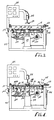
- Figure 3 is a side view of a screen assembly station with the screen frame displaced from the screen cloth.
- Figure 4 is a side view of the same screen assembly station with the screen frame in contact with the screen cloth.
- Figure 5 is a cross-sectional elevation of a portion of a screen cloth tensioning frame.
- Figure 6 is a cross-sectional side view of a portion of heating elements and the mounting therefor.
- Figure 7 is a perspective view of a completed screen assembly.
- Figure 7 illustrates an assembled tensioned screen including a rigid screen frame 10 and screen cloth 12 bonded to the screen frame 10 in tension.
- a center disc 14 may be used and is shown positioned on and bonded to the middle of the screen cloth 12.
- the center disc 14 includes two disc elements one on either side of the screen. These elements are bonded by adhesive through the screen.
- a rubber gasket or room temperature cured elastomeric material may be positioned at the periphery of the two disc members to both retain the bonding adhesive between the two disc members during curing and to seal any cracks or cavities in the center disc structure.
- the screen cloth comes in a wide variety of screen patterns and mesh sizes and is, in the preferred embodiment, most commonly of stainless steel. Nylon, polyester and other synthetic materials are also used.
- the screen frame 10 itself, like the screen cloth 12, is generally conventional with an upper surface 16 forming a bonding surface for association of the screen cloth 12 in bonded relationship therewith.
- the screen frame 10 is preferably of fabricated stainless steel sheet forming a tubular structure which is sealed. Non metallic materials and solid construction may also be used.
- the process for manufacturing screens of the present invention is shown in this embodiment to employ a screen frame 10 which is circular in plan. However, depending on the screening equipment, rectangular or other shapes may also be employed.
- the screen frame is prepared with particular attention to the creation of an appropriate bonding surface 16. To this end, the frame is thoroughly cleaned with solvent. Additionally, the bonding surface is grit blasted to a degree of roughness which can provide optimum adhesion of the adhesive material. Quite naturally, the optimum roughness will depend on the nature of the frame material, adhesive and screen cloth. In the preferred embodiment, a roughness of around 1.6 to 3.175 micrometers (63 micro inch to 125 micro inch) has been found optimal. Following the grit blasting, and preferably just prior to assembly of the screen, the screen frame 10 is once again cleaned with solvent. Thus, a cleaned and roughened surface is presented for the bonding operation.
- the screen frame 10 is placed on a turntable 18 shown in Figure 1.
- the turntable 18 may be hand operated or motor driven. Such a turntable is employed with circular screen frames. Other carriages or the like would be appropriate for rectangular screen frames.
- a frame 20 supporting the turntable 18 is also shown supporting a second turntable 22.
- the second turntable 22 is shown to have a screen frame 10′ of smaller diameter. In this way, a multiple number of screen frame diameters may be accommodated.
- the mounting stand 24 Associated with the turntables 18 and 22 is a mounting stand 24 fixed to the frame 20.
- the mounting stand 24 supports an adhesive dispenser.
- the adhesive dispenser includes a hollow nozzle 28 and a mixing chamber 30.
- the mixing chamber 30 is in fluid communication with the nozzle 28 as are two conduits 32 and 34.
- the conduit 32 conveys material from a first reservoir 36 while the conduit 34 conveys material from a second reservoir 38.
- the material in each of the reservoirs is preferably placed under pressure and appropriately valved to be conveyed through the conduits 32 and 34 in the selected ratio to the mixing chamber 30.
- a bead of adhesive 39 may be deposited on the bonding surface 16 of the screen frame 10. Most conveniently the bead 39 is placed centrally on the bonding surface 16. Depending on the desired final product or the flow characteristics of the adhesive, the bead 39 may be deposited either inwardly or outwardly of the center of the bonding surface 16.
- a dispenser 40 is also mounted to the mounting stand 24. The second dispenser 40 includes a nozzle 42 appropriately directed to the inner edge of the screen frame 10.
- a conduit 44 conveys pressurized, unvulcanized elastomer from a reservoir 46. Again, by selecting the proper speed of the turntable 22 and nozzle configuration, the proper sized unvulcanized elastomer bead 48 may be deposited.
- the adhesive bead 39 is shown to be placed centrally on the bonding surface 16.
- the unvulcanized elastomer bead 48 is positioned adjacent to the adhesive bead 39 at the inner edge of the screen frame 10.
- a similar elastomer bead may also be placed at the outer edge of the screen frame 10.
- Sufficient adhesive 39 is positioned on the bonding surface 16 such that it will appropriately cover the bonding surface and extend into the through the screen cloth 12 when positioned on the screen frame 10.
- the unvulcanized elastomeric bead 48 provides an initial function during fabrication of a screen to keep the adhesive 39 from flowing to the inner edge of the bonding surface 16. As has been long recognized, hard bonding materials or other rigid retaining devices are inappropriate for placement at the inner edge of a screen frame 10. Further, an elastomer is preferably located at such an inner edge to provide a transition for the screen cloth 12 in the final screen. Regardless of how taut the screen cloth may be, when used in a vibratory device, the screen cloth will vibrate in directions normal to the plane of the screen frame 10. If the transition between the unbonded and bonded screen cloth areas is rigid, high stress exists at that point and fatigue failure can occur. With an elastomer providing a transition between the unbonded screen cloth and the bonded screen cloth, the point of high stress is dissipated across the elastomer and fatigue failure is less likely.
- the screen frame 10 is taken to a screen frame assembly station.
- the screen assembly station is shown in the preferred embodiment in Figures 3 and 4 to include a support frame 50.
- the support frame 50 accommodates a plateform and a screen cloth tensioning frame along with the requisite controls.
- the platform includes a lift table 52 which is shown to include an air or hydraulic cylinder 54.
- the cylinder is controlled by a conventional valve control mechanism 56 to lift a piston structure 58.
- the lift table 52 is conveniently planar and is fixed to the piston structure 58 at its center. When employed with circular screens, the lift table 52 may also be circular.
- the cylinder 54 is arranged to present two limit positions of the lift table 52.
- a first limit position is shown in Figure 3. This first position has the lift table 52 and all equipment mounted thereon in a retracted position at the lower end of the stroke of the cylinder 54.
- a second extreme position is illustrated in Figure 4 with the lift table 52 raised to a second limit.
- the heater for the screen cloth will be placed closer than illustrated; however, the spacing depicted provides clarity of illustration.
- the screen cloth tensioning frame 62 is conveniently formed in a rectangular or square configuration, the construction of which can best be seen in Figure 5.
- the frame 62 includes frame members 64 which each have a guide surface 66 and a mounting flange 68.
- the mounting flange 68 is located on the outer side of the frame member 64 with the guide surface 66 inwardly thereof.
- Positioned on each of the frame members 64 is a tensioning rail 70.
- the tensioning rail 70 includes an upper member 72 and a lower member 74.
- the members 72 and 74 are brought together by bolts 76 which act to compress and grip screen cloth 12 positioned between the define the plane of the screen cloth tensioning frame.
- a screen may be gripped on all four sides by tensioning rails 70 and held with sufficient strength such that the screen may be tensioned as desired.
- each of the four sides of the screen cloth tensioning frame 62 are provided with tensioning studs 78.
- the tensioning studs 78 are threaded into the lower member 74 and extend through holes 80 in the mounting flange 68.
- the outer end of each tensioning stud 78 is also threaded to receive a tensioning nut 82.
- a coil spring 84 Positioned on each tensioning stud 78 between the mounting flange 68 and the tensioning nut 82 is a coil spring 84.
- Mounting collars 86 and 88 are positioned at the ends of the coil spring 84 and in turn extend against the mounting flange 68 and the tensioning nut 82. By tightening the tension nut 82 on the tensioning stud 78, the spring 84 is compressed. This pulls the tensioning stud 78 through the mounting flange 68 to draw the tensioning rail 70 outwardly.
- a resilient mounting is provided which can accommodate expansion and contraction of the screen cloth and maintain roughly the same tension on the screen cloth.
- the desirable tension to be achieved in the final product approximates the tension introduced into the screen cloth 12 when first placed in the screen cloth tensioning frame 62.
- an optimum preassembly tension may be introduced to the screen cloth 12 in the screen cloth tensioning frame 62.
- the ultimate tension in the completed screen preferably approaches the maximum permissible screen tension recommended by the screen cloth manufacturer.
- a sheet heater is mounted thereto with an insulated plate 90 positioned above and spaced from the table 52.
- spacing bolt assemblies 92 are employed at both the inner circular edge 94 and the outer circular edge 96 of the insulated plate 90.
- air may blow through the space beneath the insulated plate 90 and above the lift table 52.
- a heating blanket 98 Positioned on the insulated plate 90 is a heating blanket 98.
- the heating blanket is typically of vulcanized silicone material with heating coils extending therethrough.
- the heating blanket 98 has roughly the same area in plan as the insulated plate 90 upon which it sits.
- the aluminum plate 100 is designed to evenly disperse the heat from the heating blanket 98 such that the overall assembly presents a uniform source of heat across the requisite area to operate as a sheet heater.
- empirical observation may be conveniently used to define the appropiate thickness of the aluminum plate 100 such that it heats quickly to expedite the cycle and yet is of sufficient thickness to adequately disperse the heat of the coils in the heating blanket 98.
- heating elements 102 and 104 Positioned radially outwardly of the sheet heater are two heating elements 102 and 104. These elements 102 and 104 extend just outwardly of the periphery of the sheet heater at a diameter to accommodate the screen frame 10. Each of the heating elements 102 and 104 is mounted in a plurality of mounting clips 106 as best illustrated in Figure 6.
- the mounting clips may conveniently be eye-bolts with the top portion of the circular head cut off to accommodate the heat element.
- Lock nuts 108 are positioned below the lift table 52 and fixedly threaded on the mounting clips 106.
- a compression spring 110 with mounting collars 112 and 114 at either end is positioned on each shaft of each mounting clip 106.
- the mounting clips 106 are located in this fashion about the lift table 52 with the clips of each of the two heating elements 102 and 104 being staggered in their position so as not to interfere with one another. Insulation may or may not be provided between the clips in the heating elements depending on the elements and the performance requirements.
- the screen frame 10 rests directly on the heating elements 102 and 104 for rapid heat conduction into the screen frame. Indirect heating may also be used.
- the resilient mounting of the heating elements 102 and 104 also allows the screen frame 10 positioned thereon to be resiliently placed for its later interaction with the screen cloth 12 during bonding.
- heat lamps for example, illustrated in phantom as 115 may be employed where the screen frame is non conductive or requires an uneconomical length of time to heat sufficiently.
- This heater may be a simple heating coil in association with a plate.
- blowers 120 Also associated with the lift table 52 four blowers 120. Four such blowers are found in the preferred embodiment.
- the blowers 120 include intakes 122 located below the lift table 52.
- the blower exhausts 124 are directed into the space between the lift table 52 and the insulated plate 90. Flow from these blowers is thus primarily directed outwardly to the area of the heating elements 102 and 104 and any screen frame 10 positioned thereon.
- the nature of the insulated plate 90 prevents the blowers from affecting the temperature of the heating blanket 98 or aluminum plate 100 and in turn the screen cloth 12.
- the temperature controller 126 controls power through conduits 128, 130, 132 and 134 to the heating elements 102 and 104, the heating blanket 98, the center disc heater 116 and the blowers 120, respectively. The control of these components will be discussed more fully in the description of the process below.
- the air cylinder 136 operates a piston having a broad head 138.
- the broad head is capable of being brought down into the plane of the screen cloth tensioning frame 62 to compress the screen cloth 12 and the two elements of the center disc 14 together using the center disc heater 116 as an anvil.
- the adhesive employed for bonding in the present invention presents significant beneficial characteristics applicable to use in bonding screen cloth to a screen frame.
- the preferred ingredients are presented in a two-part adhesive mixture.
- the epoxy resin is considered by the FDA as suitable for food contact when properly formulated and cured and may be advantageously cured at an elevated temperature.
- this resin When employed in the adhesive, this resin is highly chemically resistent, due in part to substantial cross linking.
- the practical range for this resin by weight percent in part A of the adhesive is about 38.5% wt. to 68.5% wt. As the change in the percent amount of resin is largely accommodated by a change in the percent amount of the amorphous silica, mixtures at the higher end of this range are very fluid and at the lower end are very viscous.
- the amorphous silica presents improved chemical resistance to the bond such that the bond is substantially inert in most applications presently known where the screen itself is also not chemically reactive.
- the silica also contributes to advantageous flow control for placement of the bead 39 on the screen frame 10 and for flow of the adhesive through the screen cloth 12 when the screen frame 10 and screen cloth 12 are brought together.
- the silica particles have been found to improve bonding; although the specific mechanism for such improvement is not fully understood. The effect has been noticed with the finer mesh sizes of screen cloth. It may be that the amorphous silica particles hold the screen cloth 12 away from the screen frame 10 to some very small degree such that the thickness of the bond can be advantageously increased.
- the particle size for the silica which has been used in the preferred embodiment with success fits the following profile: Amorphous grain size 100% below 15 microns 99% below 10 microns 76% below 5 microns Mean particles size is 2.2 microns.
- the amorphous silica adds to the abrasion resistance of the material, which extends slightly above the screen cloth and to its chemical resistance.
- the amorphous silica also is believed to contribute to the coefficient of expansion such that the bond acquires a coefficient sufficiently similar to the coefficient of thermal expansion of the screen frame 10 that the bond is not deteriorated by thermal stresses in use.
- Crystalline silica may also be used with similar results. However, crystalline silica is very hard on the mixing equipment and, for that reason, is not preferred.
- the practical range for the silica in Part A of the adhesive is best understood in combination with the titanium dioxide. The range for both inert ingredients together is about 30% wt. to 60% wt.
- the titanium dioxide contributes opacity to the bond, making it an opaque white.
- This inert ingredient may be replaced by either amorphous silica or by another inert pigment.
- the fumed silica or alternately the precipitated silica in twice the percent weight, contributes flow control, viscosity and an appropriate thixotropic index. Flow control and the thixotropic index are also effected by the glycerin. With the foregoing ingredients affecting flow control, a number of advantages are realized.
- a proper bead is created on the upper surface of the screen frame.
- the adhesive material 39 properly passes through the screen cloth 12 while leaving a bond thickness between the screen frame 10 and the screen cloth 12 understood to be due principally to the amorphous silica.
- the material 39 also properly knits together on top of the screen cloth 12 to form an appropriate adhesive structure in the cured state.
- the practical range for fumed silica is about 0.5% wt.
- the range for precipitated silica is about 1.0% wt. to 7.0% wt.
- the range for the glycerin is about 0.1% wt. to 1.0% wt.
- the fumed or precipitated silica works synergistically with the glycerin to create appropriate thixotropic properties.
- the amine adduct also known as modified aliphatic polyamine, is presented as the second part of the adhesive.
- This epoxy resin hardener is mixed at 16.5 parts by weight of 100.0 parts per weight of the first part of the adhesive.
- a suitable such hardener is sold under the trade name "Ancamine 1916" by Pacific Anchor Chemical Corp. of Los Angeles, California, which is a reaction product of diethylene triamine (DETA) and a bisphenol-A epoxy resin.
- DETA diethylene triamine
- the hardener should be understood to have a proportional range, to the amount of resin. Therefore, the hardener would have a range of about 10 to 20 parts per 100 parts of Part A of the adhesive by weight. As with all of the aforementioned components, this hardener is considered by the FDA as suitable for food contact when properly formulated and cured.
- a length of screen cloth 12 of a selected material is positioned in the screen cloth tensioning frame 62 by gripping the edge of the screen cloth 12 by the tensioning rail 70.
- the screen cloth 12 may be tensioned.
- tensioning nuts 82 are tightened to achieve a preselected amount of tension. The tension is such that, through experience, it will result in the desired final tension within the screen cloth 12 when associated with the screen frame 10.
- the tensioning of the screen is performed prior to placement of the adhesive and elastomer on the screen frame.
- the lower member of the center disc 14 is placed on the center disc heater 116 and the screen frame 10 is placed on the heating elements 102 and 104.
- the screen frame with uncured adhesive 39 and unvulcanized elastomer 48 is positioned for assembly with the screen cloth 12 located and tensioned in the screen cloth tensioning frame 62.
- the lift table 52 is shown to be driven by an air cylinder. A hydraulic cylinder could also be employed or equivalent mechanical means.
- the lift table is shown in its lowered position in Figure 3 and is shown in its upper, extended position in Figure 4. With the screen frame 10 in position, the lift table may be raised to its upper position to assemble the screen cloth 12 with the screen frame 10.
- the lift table 52 is positioned such that the aluminum plate 100 atop the heating blanket 98 forming the sheet heater approaches but preferably does not contact the underside of the screen cloth 12. If the sheet heater were to contact the screen cloth, the process would also work. However, it is likely that the screen cloth would be discolored by the heat.
- the screen frame 10 sitting upon the heating elements 102 and 104 is brought into pressurized contact with the screen cloth 12.
- the lower element of the center disc 14 may also be brought into contact with the screen cloth 12.
- the resilient mountings on the heating elements 102 and 104 cause the screen frame to come into uniform contact with the screen cloth 12 and provide a substantially constant pressure of the screen frame 10 against the screen cloth 12. This pressure forces the adhesive bead 39 up through the screen mesh to immerse an annular portion of the screen cloth 12 in the adhesive 39 at the bond surface of the screen frame 10.
- the screen frame 10 is heated by the heating elements 102 and 104.
- the contact between the heating elements 102 and 104 and the metallic screen frame 10 provides for rapid heating to expedite the entire process.
- an array of heat lamps or other conventional heating mechanisms would be employed to elevate the temperature of the adhesive 39 to a proper cure temperature.
- a ramp/soak cycle is employed controlled by the temperature controller 126.
- Such a heating procedure would bring the temperature of the coils up to a specified temperature above the target temperature. At this point, the temperature is lowered to the target temperature and maintained at that temperature. Consequently, a first surge of heat is distributed to the screen frame 10 to bring the screen frame 10 quickly up to an appropriate temperature.
- a steady state temperature is maintained by the heating elements 102 and 104.
- the target temperature is between 66°C and 149°C (150° F and 300° F) with a cycle time of 20 minutes. The performance of the adhesive will dictate the actual time and temperature conditions.
- the heating elements 102 and 104 are turned off.
- the screen cloth is also heated using the sheet heater immediately adjacent to the screen but slightly spaced therefrom.
- the heating blanket 98 is controlled by the temperature controller 126 to raise the temperature of the screen cloth to a range of 66°C and 149°C (150° F to 300° F). As the temperature of the screen cloth is raised, the screen cloth expands. The tension on the screen cloth is maintained even with this expansion due to the resilient elements associated with the screen cloth tensioning frame 62.
- the heating of the screen frame 10 and the screen cloth 12 are conducted in such a manner that they expand to roughly the same extent. In this way, when the bond is complete and the screen assembly cooled, it will maintain the desired uniform tension in the screen cloth 12.
- the frame and screen Prior to curing of the adhesive, the frame and screen can experience some relative movement. Care must be taken to avoid too much relative movement between these components as it would spread the adhesive or elastomer beyond appropriate limits on the screen frame 10.
- the heating of the screen frame 10 only moderately affects the action of the unvulcanized elastomer.
- silicone which is room temperature vulcanizing.
- the screen frame 10 begins to cool. This cooling is enhanced by the blowers 120 which direct air into the space between the lift table 52 and the insulated plate 90. This forced air moves outwardly to blow over the screen frame 10 for cooling. With this cooling, the screen frame 10 contracts.
- the screen cloth 12 is of a structure that must be assumed to cool almost instantly. Once heat is removed from the screen cloth, temperature falls very rapidly which in turn results in contraction of the screen cloth. If the screen frame 10 cools slowly and the screen cloth 12 cools rapidly, the tension in the screen cloth will increase to jeopardize both the bond and the integrity of the screen cloth itself. If the yield point of the screen cloth is reached, the screen will stretch permanently and tension will be lost when the screen assembly is cooled.
- the sheet heater assembly is either left on or contains sufficient latent heat that the screen cloth 12 does not cool faster than the screen frame 10.
- the center disc is also bonded to the screen.
- the lower element of the center disc 14 is properly placed in the center of the screen.
- the center disc heater 116 is simply left on at all times at the appropriate temperature for bonding of the adhesive.
- a gasket or bead of elastomer is placed at the periphery of the disc and a cup of adhesive is poured onto the screen cloth above the lower disc element. The upper disc element is then positioned and held in compression by the head 138 until bonding occurs.
- the lift table is lowered and the bonded screen is removed.
- the excess screen cloth extending beyond the periphery of the screen frame 10 is cut off and the outer edge is ground to a smooth surface. If the tension is appropriately maintained, the screen is ready for use once the elastomer has cured.
Landscapes
- Engineering & Computer Science (AREA)
- Mechanical Engineering (AREA)
- Chemical & Material Sciences (AREA)
- General Chemical & Material Sciences (AREA)
- Physics & Mathematics (AREA)
- Chemical Kinetics & Catalysis (AREA)
- Composite Materials (AREA)
- Thermal Sciences (AREA)
- Textile Engineering (AREA)
- Manufacturing & Machinery (AREA)
- Fluid Mechanics (AREA)
- Adhesives Or Adhesive Processes (AREA)
- Laminated Bodies (AREA)
- Lining Or Joining Of Plastics Or The Like (AREA)
- Treatment Of Fiber Materials (AREA)
Description
- The field of the present invention is screens which are tensioned for use in separating and the like along with the apparatus, process and materials for the manufacture of such tensioned screens.
- Metal screen cloth as well as many other suitable materials have long been employed in tensioned conditions for the processing of materials, the stripping of liquids and the like. Such tensioned screens often include both the screen cloth and a structural screen frame to which the screen cloth is strongly attached. The attachment of the tensioned screen cloth to the screen frame has conventionally taken many forms including mechanical interlocking elements, upper and lower frame elements either welded or bonded together with the screen in between and simple bonding of screen cloth to the screen frame without additional mechanical restraint.
- A primary difficulty which has been encountered in the manufacture of such tensioned screens has been the maintenance of appropriate tension in the screen cloth throughout fabrication. Simple mechanical interlocking elements may be employed to tension a screen for some uses. However, such systems are expensive, complicated to assemble and adjust and have joints and cavities which are difficult to clean. Welding screen in place in a tensioned condition tends to create a lack of tension uniformity. The screen cloth between welding points is able to deform and slacken. Further, the use of a top frame element again creates joints and cavities which are difficult to properly clean, particularly if the screen is to be employed in the food processing industry.
- Another structure difficult to properly tension is the bonded screen. A structural screen frame is provided which has an upper bonding surface. Screen cloth is tensioned, adhesive is placed on the bonding surface and the screen cloth is brought against the bonding surface until the adhesive is cured. Fabrication of screens in this manner have achieved proper post fabrication tension using adhesives which cure at room temperature. However, it is generally believed that adhesives perform best when, during their use, they do not operate at temperatures in excess of the cure temperature used in the bonding of the screen components. As tensioned screens find applications in a variety of uses which require elevated temperatures, bonded screens have not proven satisfactory.
- To create a bonded, tensioned screen where the bonding occurs at an elevated temperature, the fabricator must overcome or ignore substantial problems. The tensioning of screen cloth becomes exceedingly difficult when the screen cloth is subjected to substantial temperature changes. Frequently used screen materials include metal screen cloth and metal screen frames. When either is heated, it expands. However, there is a vast difference between the heat transfer characteristics of screen cloth and screen frames. Screen cloth can be heated very rapidly while screen frames require substantial time and heat input. For the same reasons, screen frames cool much slower than screen cloth when placed in the same environment. As a practical matter, when placed in air, the screen cloth will immediately cool and attempt to contract to its normal dimensions. The frame on the other hand will only slowly cool and remain expanded long after the screen cloth has attempted to contract. Thus, if adhesives are cured at elevated temperatures in the fabrication of screens, the screen cloth is likely either to relax once heat is removed or to exceed the yield strength and permanently deform. In either instance, the resulting screen assembly lacks the appropriate tension and may suffer from other defects. A screen which is not properly tensioned can have buckled or sagging screen cloth. Buckling can cause poor flow of material being screened. Sagging inhibits transfer of vibrational energy and promotes fatigue failure.
- Certain bonded screens have been fabricated with the bonding occurring at an elevated temperature. Such a fabricating process and an assembly station for carrying out the process is disclosed in US-A-3 915 775 which provides the basis for the prior art portions of
claims 1 and 12. Thermal stress problems have been avoided in these instances by only heating the adhesive and an overlying ring. In such situations, the frame material is a poor thermal conductor, typically fibreglass. Adhesives, a tensioned screen, and a ring are positioned on the frame. Heat is then directly applied to the overlying ring until the adhesive is cured. Under these circumstances, the screen frame and the screen cloth are effectively not heated. In this way, thermal stresses between the two are avoided. - In addition to the foregoing, tensioned screens have found substantial utility in the food processing industry. Substantial requirements are placed on products in this industry. No toxic materials may be employed, the resulting products must be easy to clean and the products must not interact with the substances being processed. Many tensioned screen designs have difficulty meeting these requirements because of the selection of materials and adhesives or because of the creation of cavities and joints which are not easily cleaned. Abrasion and bond deterioration under heat can specifically affect bonded screens in use.
- The present invention is directed to tensioned screens and the process and apparatus for making such screens. The screens are bonded under tension at an elevated temperature in a process and apparatus as defined in claims 1 and 9 respectively which allows the resulting product to be properly tensioned for subsequent use. A screen cloth heating system and a screen frame heating and cooling system may be used to provide for proper tensioning and stress control of the screen cloth for a well tensioned final product. Elevated temperatures are employed for the curing of adhesive to enhance the resultant product structure and capabilities.
- In a further aspect of the present invention, the apparatus for fabricating screen assemblies may include mechanisms for providing the proper heat profile to the components being assembled and for accommodating thermal expansion of the assembly during the fabrication process. A sheet heater may be employed adjacent to and roughly coextensive with the screen cloth inwardly of the screen frame for proper expansion of the screen cloth. Heating elements may be employed in direct contact or in close proximity with the screen frame for creating the appropriate bonding temperature for the adhesive. Resilient mechanisms may be employed for maintaining proper screen tension and for providing appropriate compression force between the screen frame and screen cloth at the bond. Air blowers may be used to selectively cool portions of the final assembly for reduced processing time.
- In another aspect of the present invention uniquely formulated adhesive is employed to create an appropriate bond at elevated temperatures which has good abrasion characteristics, good chemical resistance, good strength and good expansion characteristics compatible with the screen frames. Amorphous silica is employed in proper proportion with epoxy resin to create appropriate thermal, structural and abrasion characteristics. The adhesive further exhibits advantageous thixotropic and viscosity characteristics through the employment of fumed or precipitated silicon dioxide and glycerin. These characteristics contribute to the properties of the material advantageous for flow and orientation of the adhesive during the bonding process. The selected materials may also be nontoxic to enhance the applicability of the screen assemblies for food processing uses.
- The construction of the screen and the selection of materials in keeping with the practice of the present invention lend themselves to providing a structure with uniform tensioned screen cloth, alkali, acid and solvent resistent properties, simple and sound construction without hard-to-clean joints and cavities and materials acceptable for food processing. Accordingly, it is an object of the present invention to provide an improved final tensioned screen product through its materials, process and apparatus of manufacture. Further objects and advantages will appear hereinafter.
- Figure 1 is a side view of an adhesive application station.
- Figure 2 is a cross-sectional side view of a screen frame with adhesive and elastomer positioned thereon.
- Figure 3 is a side view of a screen assembly station with the screen frame displaced from the screen cloth.
- Figure 4 is a side view of the same screen assembly station with the screen frame in contact with the screen cloth.
- Figure 5 is a cross-sectional elevation of a portion of a screen cloth tensioning frame.
- Figure 6 is a cross-sectional side view of a portion of heating elements and the mounting therefor.
- Figure 7 is a perspective view of a completed screen assembly.
- Turning in detail to the drawing, Figure 7 illustrates an assembled tensioned screen including a
rigid screen frame 10 andscreen cloth 12 bonded to thescreen frame 10 in tension. Acenter disc 14 may be used and is shown positioned on and bonded to the middle of thescreen cloth 12. Thecenter disc 14 includes two disc elements one on either side of the screen. These elements are bonded by adhesive through the screen. A rubber gasket or room temperature cured elastomeric material may be positioned at the periphery of the two disc members to both retain the bonding adhesive between the two disc members during curing and to seal any cracks or cavities in the center disc structure. The screen cloth comes in a wide variety of screen patterns and mesh sizes and is, in the preferred embodiment, most commonly of stainless steel. Nylon, polyester and other synthetic materials are also used. Thescreen frame 10 itself, like thescreen cloth 12, is generally conventional with anupper surface 16 forming a bonding surface for association of thescreen cloth 12 in bonded relationship therewith. Thescreen frame 10 is preferably of fabricated stainless steel sheet forming a tubular structure which is sealed. Non metallic materials and solid construction may also be used. - The process for manufacturing screens of the present invention is shown in this embodiment to employ a
screen frame 10 which is circular in plan. However, depending on the screening equipment, rectangular or other shapes may also be employed. The screen frame is prepared with particular attention to the creation of anappropriate bonding surface 16. To this end, the frame is thoroughly cleaned with solvent. Additionally, the bonding surface is grit blasted to a degree of roughness which can provide optimum adhesion of the adhesive material. Quite naturally, the optimum roughness will depend on the nature of the frame material, adhesive and screen cloth. In the preferred embodiment, a roughness of around 1.6 to 3.175 micrometers (63 micro inch to 125 micro inch) has been found optimal. Following the grit blasting, and preferably just prior to assembly of the screen, thescreen frame 10 is once again cleaned with solvent. Thus, a cleaned and roughened surface is presented for the bonding operation. - Once properly prepared, the
screen frame 10 is placed on aturntable 18 shown in Figure 1. Theturntable 18 may be hand operated or motor driven. Such a turntable is employed with circular screen frames. Other carriages or the like would be appropriate for rectangular screen frames. Aframe 20 supporting theturntable 18 is also shown supporting asecond turntable 22. Thesecond turntable 22 is shown to have ascreen frame 10′ of smaller diameter. In this way, a multiple number of screen frame diameters may be accommodated. - Associated with the
turntables stand 24 fixed to theframe 20. The mountingstand 24 supports an adhesive dispenser. The adhesive dispenser includes ahollow nozzle 28 and a mixingchamber 30. The mixingchamber 30 is in fluid communication with thenozzle 28 as are twoconduits conduit 32 conveys material from afirst reservoir 36 while theconduit 34 conveys material from asecond reservoir 38. The material in each of the reservoirs is preferably placed under pressure and appropriately valved to be conveyed through theconduits chamber 30. By providing the appropriate pressure and nozzle characteristics for the adhesive employed, an even flow of material may be dispensed through thenozzle 28 onto a screen frame on one of the turntables. Through adjustment of the speed of theturntable 18 and the flow of material from thenozzle 28, a bead of adhesive 39, shown in the cross section of Figure 2, may be deposited on thebonding surface 16 of thescreen frame 10. Most conveniently thebead 39 is placed centrally on thebonding surface 16. Depending on the desired final product or the flow characteristics of the adhesive, thebead 39 may be deposited either inwardly or outwardly of the center of thebonding surface 16. Adispenser 40 is also mounted to the mountingstand 24. Thesecond dispenser 40 includes anozzle 42 appropriately directed to the inner edge of thescreen frame 10. Aconduit 44 conveys pressurized, unvulcanized elastomer from areservoir 46. Again, by selecting the proper speed of theturntable 22 and nozzle configuration, the proper sizedunvulcanized elastomer bead 48 may be deposited. - The
adhesive bead 39 is shown to be placed centrally on thebonding surface 16. Theunvulcanized elastomer bead 48 is positioned adjacent to theadhesive bead 39 at the inner edge of thescreen frame 10. A similar elastomer bead may also be placed at the outer edge of thescreen frame 10. One advantage of doing so is to create an adhesive cavity between the two elastomer beads. Sufficient adhesive 39 is positioned on thebonding surface 16 such that it will appropriately cover the bonding surface and extend into the through thescreen cloth 12 when positioned on thescreen frame 10. - The unvulcanized
elastomeric bead 48 provides an initial function during fabrication of a screen to keep the adhesive 39 from flowing to the inner edge of thebonding surface 16. As has been long recognized, hard bonding materials or other rigid retaining devices are inappropriate for placement at the inner edge of ascreen frame 10. Further, an elastomer is preferably located at such an inner edge to provide a transition for thescreen cloth 12 in the final screen. Regardless of how taut the screen cloth may be, when used in a vibratory device, the screen cloth will vibrate in directions normal to the plane of thescreen frame 10. If the transition between the unbonded and bonded screen cloth areas is rigid, high stress exists at that point and fatigue failure can occur. With an elastomer providing a transition between the unbonded screen cloth and the bonded screen cloth, the point of high stress is dissipated across the elastomer and fatigue failure is less likely. - Once the
adhesive bead 39 and theunvulcanized elastomer bead 48 are formed on thescreen frame 10, thescreen frame 10 is taken to a screen frame assembly station. The screen assembly station is shown in the preferred embodiment in Figures 3 and 4 to include asupport frame 50. Thesupport frame 50 accommodates a plateform and a screen cloth tensioning frame along with the requisite controls. The platform includes a lift table 52 which is shown to include an air orhydraulic cylinder 54. The cylinder is controlled by a conventionalvalve control mechanism 56 to lift apiston structure 58. The lift table 52 is conveniently planar and is fixed to thepiston structure 58 at its center. When employed with circular screens, the lift table 52 may also be circular. Thecylinder 54 is arranged to present two limit positions of the lift table 52. A first limit position is shown in Figure 3. This first position has the lift table 52 and all equipment mounted thereon in a retracted position at the lower end of the stroke of thecylinder 54. A second extreme position is illustrated in Figure 4 with the lift table 52 raised to a second limit. Typically the heater for the screen cloth will be placed closer than illustrated; however, the spacing depicted provides clarity of illustration. - Also supported by the
support frame 50 is a screen cloth tensioning frame, generally designated 62. The screencloth tensioning frame 62 is conveniently formed in a rectangular or square configuration, the construction of which can best be seen in Figure 5. Theframe 62 includesframe members 64 which each have aguide surface 66 and a mountingflange 68. The mountingflange 68 is located on the outer side of theframe member 64 with theguide surface 66 inwardly thereof. Positioned on each of theframe members 64 is atensioning rail 70. Thetensioning rail 70 includes anupper member 72 and alower member 74. Themembers bolts 76 which act to compress andgrip screen cloth 12 positioned between the define the plane of the screen cloth tensioning frame. Thus, a screen may be gripped on all four sides by tensioningrails 70 and held with sufficient strength such that the screen may be tensioned as desired. - To resiliently hold the tensioning rails 70 in tension, resilient elements are provided. These elements may take the four of springs or pneumatic elements. In the preferred embodiment, each of the four sides of the screen
cloth tensioning frame 62 are provided withtensioning studs 78. Thetensioning studs 78 are threaded into thelower member 74 and extend throughholes 80 in the mountingflange 68. The outer end of eachtensioning stud 78 is also threaded to receive atensioning nut 82. Positioned on eachtensioning stud 78 between the mountingflange 68 and thetensioning nut 82 is a coil spring 84. Mountingcollars flange 68 and thetensioning nut 82. By tightening thetension nut 82 on thetensioning stud 78, the spring 84 is compressed. This pulls thetensioning stud 78 through the mountingflange 68 to draw thetensioning rail 70 outwardly. By selecting a spring of sufficient length and rate, a resilient mounting is provided which can accommodate expansion and contraction of the screen cloth and maintain roughly the same tension on the screen cloth. - The desirable tension to be achieved in the final product approximates the tension introduced into the
screen cloth 12 when first placed in the screencloth tensioning frame 62. Through empirical results and adjustments to the heating cycles, an optimum preassembly tension may be introduced to thescreen cloth 12 in the screencloth tensioning frame 62. The ultimate tension in the completed screen preferably approaches the maximum permissible screen tension recommended by the screen cloth manufacturer. - Returning to the components positioned on the lift table 52, a sheet heater is mounted thereto with an
insulated plate 90 positioned above and spaced from the table 52. To space theinsulated plate 90 from the table 52,spacing bolt assemblies 92 are employed at both the innercircular edge 94 and the outercircular edge 96 of theinsulated plate 90. Thus, for reasons which will become apparent, air may blow through the space beneath theinsulated plate 90 and above the lift table 52. Positioned on theinsulated plate 90 is aheating blanket 98. The heating blanket is typically of vulcanized silicone material with heating coils extending therethrough. Theheating blanket 98 has roughly the same area in plan as theinsulated plate 90 upon which it sits. On top of theheating blanket 98 in analuminum plate 100. Thealuminum plate 100 is designed to evenly disperse the heat from theheating blanket 98 such that the overall assembly presents a uniform source of heat across the requisite area to operate as a sheet heater. Thus, empirical observation may be conveniently used to define the appropiate thickness of thealuminum plate 100 such that it heats quickly to expedite the cycle and yet is of sufficient thickness to adequately disperse the heat of the coils in theheating blanket 98. - Positioned radially outwardly of the sheet heater are two
heating elements elements screen frame 10. Each of theheating elements clips 106 as best illustrated in Figure 6. The mounting clips may conveniently be eye-bolts with the top portion of the circular head cut off to accommodate the heat element.Lock nuts 108 are positioned below the lift table 52 and fixedly threaded on the mounting clips 106. Acompression spring 110 with mountingcollars clip 106. The mountingclips 106 are located in this fashion about the lift table 52 with the clips of each of the twoheating elements screen frame 10 rests directly on theheating elements heating elements screen frame 10 positioned thereon to be resiliently placed for its later interaction with thescreen cloth 12 during bonding. Alternatively, heat lamps for example, illustrated in phantom as 115, may be employed where the screen frame is non conductive or requires an uneconomical length of time to heat sufficiently. - Centrally located on the lift table 52 is a
center disc heater 116. This heater may be a simple heating coil in association with a plate. - Also associated with the lift table 52 four
blowers 120. Four such blowers are found in the preferred embodiment. Theblowers 120 includeintakes 122 located below the lift table 52. The blower exhausts 124 are directed into the space between the lift table 52 and theinsulated plate 90. Flow from these blowers is thus primarily directed outwardly to the area of theheating elements screen frame 10 positioned thereon. The nature of theinsulated plate 90 prevents the blowers from affecting the temperature of theheating blanket 98 oraluminum plate 100 and in turn thescreen cloth 12. - Also mounted to the
support frame 50 is a microprocessor basedtemperature controller 126. Thetemperature controller 126 controls power throughconduits 128, 130, 132 and 134 to theheating elements heating blanket 98, thecenter disc heater 116 and theblowers 120, respectively. The control of these components will be discussed more fully in the description of the process below. - Also affixed to the
support frame 50 is anair cylinder 136. Theair cylinder 136 operates a piston having abroad head 138. The broad head is capable of being brought down into the plane of the screencloth tensioning frame 62 to compress thescreen cloth 12 and the two elements of thecenter disc 14 together using thecenter disc heater 116 as an anvil. - The adhesive employed for bonding in the present invention presents significant beneficial characteristics applicable to use in bonding screen cloth to a screen frame. The preferred ingredients are presented in a two-part adhesive mixture. The following constitute a preferred adhesive:
Part A - 100 parts by weight Bisphenol F epoxy resin 56.85% wt. Silicon dioxide in the form of amorphous silica 32.76% wt. Titanium dioxide 6.90% wt. Fumed silicon dioxide (precipitated SiO₂ may also be used at twice the amount of the fumed SiO₂) 3.17% wt. Glycerin 0.32% wt. Part B - 16.5 parts by weight Amine adduct hardener 100% wt. - Naturally, a range of the proportions of the foregoing ingredients may provide the same or selected characteristics of the bond. The epoxy resin is considered by the FDA as suitable for food contact when properly formulated and cured and may be advantageously cured at an elevated temperature. When employed in the adhesive, this resin is highly chemically resistent, due in part to substantial cross linking. The practical range for this resin by weight percent in part A of the adhesive is about 38.5% wt. to 68.5% wt. As the change in the percent amount of resin is largely accommodated by a change in the percent amount of the amorphous silica, mixtures at the higher end of this range are very fluid and at the lower end are very viscous.
- The amorphous silica presents improved chemical resistance to the bond such that the bond is substantially inert in most applications presently known where the screen itself is also not chemically reactive. The silica also contributes to advantageous flow control for placement of the
bead 39 on thescreen frame 10 and for flow of the adhesive through thescreen cloth 12 when thescreen frame 10 andscreen cloth 12 are brought together. The silica particles have been found to improve bonding; although the specific mechanism for such improvement is not fully understood. The effect has been noticed with the finer mesh sizes of screen cloth. It may be that the amorphous silica particles hold thescreen cloth 12 away from thescreen frame 10 to some very small degree such that the thickness of the bond can be advantageously increased. The particle size for the silica which has been used in the preferred embodiment with success fits the following profile:
Amorphous grain size
100% below 15 microns
99% below 10 microns
76% below 5 microns
Mean particles size is 2.2 microns.
In the cured condition, the amorphous silica adds to the abrasion resistance of the material, which extends slightly above the screen cloth and to its chemical resistance. The amorphous silica also is believed to contribute to the coefficient of expansion such that the bond acquires a coefficient sufficiently similar to the coefficient of thermal expansion of thescreen frame 10 that the bond is not deteriorated by thermal stresses in use. Crystalline silica may also be used with similar results. However, crystalline silica is very hard on the mixing equipment and, for that reason, is not preferred. The practical range for the silica in Part A of the adhesive is best understood in combination with the titanium dioxide. The range for both inert ingredients together is about 30% wt. to 60% wt. - The titanium dioxide contributes opacity to the bond, making it an opaque white. This inert ingredient may be replaced by either amorphous silica or by another inert pigment.
- The fumed silica, or alternately the precipitated silica in twice the percent weight, contributes flow control, viscosity and an appropriate thixotropic index. Flow control and the thixotropic index are also effected by the glycerin. With the foregoing ingredients affecting flow control, a number of advantages are realized. A proper bead is created on the upper surface of the screen frame. The
adhesive material 39 properly passes through thescreen cloth 12 while leaving a bond thickness between thescreen frame 10 and thescreen cloth 12 understood to be due principally to the amorphous silica. Thematerial 39 also properly knits together on top of thescreen cloth 12 to form an appropriate adhesive structure in the cured state. The practical range for fumed silica is about 0.5% wt. to 4.0% wt. while the range for precipitated silica is about 1.0% wt. to 7.0% wt. The range for the glycerin is about 0.1% wt. to 1.0% wt. The fumed or precipitated silica works synergistically with the glycerin to create appropriate thixotropic properties. - The amine adduct, also known as modified aliphatic polyamine, is presented as the second part of the adhesive. This epoxy resin hardener is mixed at 16.5 parts by weight of 100.0 parts per weight of the first part of the adhesive. A suitable such hardener is sold under the trade name "Ancamine 1916" by Pacific Anchor Chemical Corp. of Los Angeles, California, which is a reaction product of diethylene triamine (DETA) and a bisphenol-A epoxy resin. Looking to the range of proportions for resin set out above, the hardener should be understood to have a proportional range, to the amount of resin. Therefore, the hardener would have a range of about 10 to 20 parts per 100 parts of Part A of the adhesive by weight. As with all of the aforementioned components, this hardener is considered by the FDA as suitable for food contact when properly formulated and cured.
- Turning to the process of fabricating a tensioned screen on the screen assembly station, a length of
screen cloth 12 of a selected material is positioned in the screencloth tensioning frame 62 by gripping the edge of thescreen cloth 12 by thetensioning rail 70. Once the upper andlower members screen cloth 12 by thebolts 76, thescreen cloth 12 may be tensioned. To do so, tensioningnuts 82 are tightened to achieve a preselected amount of tension. The tension is such that, through experience, it will result in the desired final tension within thescreen cloth 12 when associated with thescreen frame 10. Typically in the preferred process, the tensioning of the screen is performed prior to placement of the adhesive and elastomer on the screen frame. - Once the
adhesive bead 39 and theunvulcanized elastomer bead 48 are positioned on thescreen frame 12, the lower member of thecenter disc 14 is placed on thecenter disc heater 116 and thescreen frame 10 is placed on theheating elements - Once positioned on the lift table 52, and more specifically on the
heating elements uncured adhesive 39 andunvulcanized elastomer 48 is positioned for assembly with thescreen cloth 12 located and tensioned in the screencloth tensioning frame 62. The lift table 52 is shown to be driven by an air cylinder. A hydraulic cylinder could also be employed or equivalent mechanical means. The lift table is shown in its lowered position in Figure 3 and is shown in its upper, extended position in Figure 4. With thescreen frame 10 in position, the lift table may be raised to its upper position to assemble thescreen cloth 12 with thescreen frame 10. - At its upper position, the lift table 52 is positioned such that the
aluminum plate 100 atop theheating blanket 98 forming the sheet heater approaches but preferably does not contact the underside of thescreen cloth 12. If the sheet heater were to contact the screen cloth, the process would also work. However, it is likely that the screen cloth would be discolored by the heat. - The
screen frame 10 sitting upon theheating elements screen cloth 12. The lower element of thecenter disc 14 may also be brought into contact with thescreen cloth 12. The resilient mountings on theheating elements screen cloth 12 and provide a substantially constant pressure of thescreen frame 10 against thescreen cloth 12. This pressure forces theadhesive bead 39 up through the screen mesh to immerse an annular portion of thescreen cloth 12 in the adhesive 39 at the bond surface of thescreen frame 10. - The
screen frame 10 is heated by theheating elements heating elements metallic screen frame 10 provides for rapid heating to expedite the entire process. Where thescreen frame 10 is not of conductive material, an array of heat lamps or other conventional heating mechanisms would be employed to elevate the temperature of the adhesive 39 to a proper cure temperature. - With the
heating elements temperature controller 126. Such a heating procedure would bring the temperature of the coils up to a specified temperature above the target temperature. At this point, the temperature is lowered to the target temperature and maintained at that temperature. Consequently, a first surge of heat is distributed to thescreen frame 10 to bring thescreen frame 10 quickly up to an appropriate temperature. After the target temperature is approached, a steady state temperature is maintained by theheating elements heating elements - The screen cloth is also heated using the sheet heater immediately adjacent to the screen but slightly spaced therefrom. The
heating blanket 98 is controlled by thetemperature controller 126 to raise the temperature of the screen cloth to a range of 66°C and 149°C (150° F to 300° F). As the temperature of the screen cloth is raised, the screen cloth expands. The tension on the screen cloth is maintained even with this expansion due to the resilient elements associated with the screencloth tensioning frame 62. The heating of thescreen frame 10 and thescreen cloth 12 are conducted in such a manner that they expand to roughly the same extent. In this way, when the bond is complete and the screen assembly cooled, it will maintain the desired uniform tension in thescreen cloth 12. Prior to curing of the adhesive, the frame and screen can experience some relative movement. Care must be taken to avoid too much relative movement between these components as it would spread the adhesive or elastomer beyond appropriate limits on thescreen frame 10. - The heating of the
screen frame 10 only moderately affects the action of the unvulcanized elastomer. Typically, silicone is employed which is room temperature vulcanizing. Thus, the vulcanizing cornences with the deposition of theinner bead 48 and is accomplished over a several hour period, completed long after thescreen cloth 12 has been bonded to thescreen frame 10. - Once the
heating elements blowers 120 which direct air into the space between the lift table 52 and theinsulated plate 90. This forced air moves outwardly to blow over thescreen frame 10 for cooling. With this cooling, thescreen frame 10 contracts. Thescreen cloth 12 is of a structure that must be assumed to cool almost instantly. Once heat is removed from the screen cloth, temperature falls very rapidly which in turn results in contraction of the screen cloth. If thescreen frame 10 cools slowly and thescreen cloth 12 cools rapidly, the tension in the screen cloth will increase to jeopardize both the bond and the integrity of the screen cloth itself. If the yield point of the screen cloth is reached, the screen will stretch permanently and tension will be lost when the screen assembly is cooled. Consequently, heat is preferably maintained in the sheet heater assembly such that thescreen cloth 12 does not contract faster than thescreen frame 10. If thescreen cloth 12 is allowed to contract at a slower rate, tension is lost momentarily in the screen cloth. However, once the screen cloth is then cooled to the temperature of thescreen frame 10, tension is restored. Thus, it is preferred that the sheet heater assembly is either left on or contains sufficient latent heat that thescreen cloth 12 does not cool faster than thescreen frame 10. - During the process of heating the
screen cloth 12 andscreen frame 10, the center disc is also bonded to the screen. With the lift table 52 in the raised position, the lower element of thecenter disc 14 is properly placed in the center of the screen. Thecenter disc heater 116 is simply left on at all times at the appropriate temperature for bonding of the adhesive. A gasket or bead of elastomer is placed at the periphery of the disc and a cup of adhesive is poured onto the screen cloth above the lower disc element. The upper disc element is then positioned and held in compression by thehead 138 until bonding occurs. - Once bonding is complete and the screen is properly cooled, the lift table is lowered and the bonded screen is removed. The excess screen cloth extending beyond the periphery of the
screen frame 10 is cut off and the outer edge is ground to a smooth surface. If the tension is appropriately maintained, the screen is ready for use once the elastomer has cured.
Claims (20)
- A process of fabricating a tensioned screen, comprising the steps of pretensioning screen cloth (12); and bonding the pretensioned screen cloth to a screen frame (10) with the assistance of applied heat, characterised in that the screen frame (10) is heated to an effective temperature for adhesive bonding, in that the screen cloth (12) is expanded by heating before being bonded to the heated screen frame, and in that heat is retained in the bonded screen cloth (12) while said screen frame (10) is cooled after said bonding step such that it does not cool more quickly than said screen frame (10) during cooling.
- A process according to claim 1, wherein adhesive (39) is applied centrally to the bonding surface (16) of the screen frame (10) by moving the screen frame (10) at a substantially constant speed beneath a flow of adhesive.
- A process according to claim 2, wherein unvulcanised elastomer (48) is applied to the screen frame (10) inwardly of the adhesive (39).
- A process according to claim 1, 2 or 3, wherein the screen frame (10) is heated to a temperature which is at least the maximum processing temperature at which the screen is intended to be used.
- A process according to claim 1, 2, 3 or 4, wherein said step of expanding the screen cloth (12) includes placing a sheet heater (98) adjacent and separated from the screen cloth (12) and activating the sheet heater (98).
- A process according to any preceding claim, wherein the screen frame (10) is heated by applying a heating element (102,104) against the screen frame (10) on a side displaced from the bonding surface of the screen frame (10).
- A process according to any one of claims 1 to 5, wherein the screen frame (10) is heated by means comprising the direction of heat from heating lamps (115) towards the bonding surface of the screen frame (10).
- A process according to any preceding claim, wherein the screen cloth (12) is pretensioned by means including resilient elements (84) to maintain the tension.
- A process according to any preceding claim, wherein the screen frame (10) is rapidly cooled after the bonding step.
- A process according to claim 9, wherein the cooling is effected by blowing air over the screen frame (10) while shielding the screen cloth (12) from the blown air.
- A process according to any preceding claim, wherein the screen cloth is bonded to the screen frame using an adhesive comprising: a first part having about 38.5% wt to 68.5% wt epoxy resin, 30% wt to 60% wt of inert ingredient from the group consisting of silica and silica with inert pigment, a thixotropic enhancer from the group consisting of 0.5% wt to 4% wt fumed silica and 1% wt to 7% wt precipitated silica, and 0.1% wt to 1% wt glycerin; and a second part having about 100% wt hardener for said epoxy resin, about 10 to 20 parts by weight of said hardener being mixed with 100 parts by weight of said first part.
- A screen assembly station for bonding screen cloth (12) to a screen frame (10), comprising a screen cloth tensioning frame (62); a platform (52) for supporting the screen frame (10), a support frame (50) for supporting said screen cloth tensioning frame (62) and said platform (52) for movement between a first position with said screen cloth tensioning frame (62) displaced from said platform (52) and a second position with said screen cloth tensioning frame (62) adjacent said platform (52) and heating means of assisting bonding in use of the assembly station characterised in that the platform (52) includes a central sheet heater (98) for heating the tensioned screen cloth (12) in use of the assembly station and a peripheral heating element (102,104) for heating the screen frame (10) extending about said central sheet heater (98).
- A screen assembly station according to claim 12, wherein said peripheral heating element (102,104) extends to adjacent the plane of said screen cloth tensioning frame (62) such that a screen frame (10) placed on said peripheral heating element (102,104) extends to the plane of said screen cloth tensioning frame (62) with said support frame (50) in said second position, and wherein said central sheet heater (98) is adjacent said screen cloth tensioning frame (62) with said support frame (50) in said second position.
- A screen assembly station according to claim 12 or 13, wherein the screen cloth tensioning frame (62) includes a tensioning rail (70) resiliently held and having means (72,74) for gripping the screen cloth (12).
- A screen assembly station according to claim 12, 13 or 14, wherein said central sheet heater (98) is circular and said peripheral heating element (102,104) is positioned adjacent the outer periphery of the circular central sheet heater (98).
- A screen assembly station according to any one of claims 12 to 15, wherein said central sheet heater (98) is adjacent but not in the plane of said screen cloth tensioning frame (62) with said support frame (50) in said second position.
- A screen assembly station according to any one of claims 12 to 16, wherein said peripheral heating element (102,104) extends to adjacent the plane of said screen cloth tensioning frame (62), such that a screen frame (10) placed on said peripheral heating element (102,104) extends to the plane of said screen cloth tensioning frame (62) with said support frame (50) in said second position.
- A screen assembly station according to any one of claims 12 to 17, wherein said platform includes a lift table (52) positioned on said support frame (50), supporting said central sheet heater (98) and said peripheral heating element (102,104), said central sheet heater (98) being spaced from said table (52), and at least one blower (120) having an outlet to between said table (52) and said central sheet heater (98).
- A screen assembly station according to any one of claims 12 to 17, wherein said central sheet heater includes a heater sheet (98) with heating elements embedded therein, and an insulated plate (90) upon which said heater sheet (98) is positioned, and a heat conducting sheet (100) positioned on said heater sheet (98), said insulated sheet (90), said heater sheet (98) and said heat conducting sheet (100) being substantially coextensive.
- A screen assembly station according to any one of claims 12 to 19, wherein said platform includes resilient mounting assemblies (110) supporting said peripheral heating element (102,104), said mounting assemblies (110) being resilient in the direction towards and away from the plane of said screen cloth tensioning frame (62).
Applications Claiming Priority (2)
| Application Number | Priority Date | Filing Date | Title |
|---|---|---|---|
| US237102 | 1988-08-26 | ||
| US07/237,102 US4968366A (en) | 1988-08-26 | 1988-08-26 | Method of manufacture of tension screens |
Publications (3)
| Publication Number | Publication Date |
|---|---|
| EP0356209A2 EP0356209A2 (en) | 1990-02-28 |
| EP0356209A3 EP0356209A3 (en) | 1991-12-04 |
| EP0356209B1 true EP0356209B1 (en) | 1994-11-30 |
Family
ID=22892347
Family Applications (1)
| Application Number | Title | Priority Date | Filing Date |
|---|---|---|---|
| EP89308517A Expired - Lifetime EP0356209B1 (en) | 1988-08-26 | 1989-08-23 | Tension screens and the method, apparatus and materials for the manufacture thereof |
Country Status (5)
| Country | Link |
|---|---|
| US (1) | US4968366A (en) |
| EP (1) | EP0356209B1 (en) |
| KR (1) | KR900002855A (en) |
| CA (1) | CA1327440C (en) |
| DE (1) | DE68919588T2 (en) |
Families Citing this family (41)
| Publication number | Priority date | Publication date | Assignee | Title |
|---|---|---|---|---|
| FR2682050B1 (en) * | 1991-10-08 | 1994-07-22 | Chauvin Sarl Ets | SCREENING DEVICE EQUIPPED WITH DECOLMATION MEANS. |
| US5238515A (en) * | 1991-11-07 | 1993-08-24 | Haworth, Inc. | Fabric securement method |
| DK0645976T4 (en) | 1992-06-15 | 2003-05-19 | Miller Herman Inc | Office chair |
| US5326470A (en) * | 1992-12-08 | 1994-07-05 | Bird Escher Wyss Inc. | Non-compressive loading of a screen basket for a pulp pressure screening apparatus |
| US5951864A (en) * | 1996-10-28 | 1999-09-14 | Emerson Electric Co. | Screening system |
| DE69827046T2 (en) * | 1997-03-01 | 2005-03-03 | United Wire Ltd. | Device for repairing or processing a filter screen |
| US6279644B1 (en) | 1997-12-24 | 2001-08-28 | St. Gobain Bayform America Inc. | Screen and frame assembly in which the screen is adhesively secured to the frame |
| US6991693B2 (en) * | 1997-12-24 | 2006-01-31 | Saint-Gobain Bayform America, Inc. | Screen cloth insertion apparatus and method |
| US6331223B1 (en) * | 1997-12-24 | 2001-12-18 | Saint-Gobain Bayform America, Inc. | Method of fabricating adhesively secured frame assembly |
| US20040112522A1 (en) * | 1998-10-30 | 2004-06-17 | Ward Kerry T. | Automated methods for making screen assemblies for vibratory separators |
| US6283303B1 (en) * | 1999-03-29 | 2001-09-04 | M-I L.L.C. | Vibrating screen separator, separating method, and clamping device |
| FR2793505B1 (en) * | 1999-05-11 | 2001-11-30 | Jean Marc Scherrer | DEVICE FOR MANUFACTURING WALL TILES |
| US6305549B1 (en) * | 1999-07-06 | 2001-10-23 | Southwestern Wire Cloth, Inc. | Vibrating screen assembly of dissimilar materials |
| US6513665B1 (en) | 1999-11-02 | 2003-02-04 | M-I L.L.C. | Screen mounting system |
| US7396082B2 (en) | 2002-03-29 | 2008-07-08 | Garrex Llc | Task chair |
| US7625046B2 (en) | 2002-03-29 | 2009-12-01 | Garrex Llc | Task chair |
| US7040703B2 (en) | 2002-03-29 | 2006-05-09 | Garrex Llc | Health chair a dynamically balanced task chair |
| DE60236629D1 (en) * | 2002-05-08 | 2010-07-15 | United Wire Ltd | MANUFACTURE OF A FILTER SCREEN |
| US6997325B2 (en) | 2002-11-13 | 2006-02-14 | M-I L.L.C. | System and process for break detection in porous elements for screening or filtering |
| US20050056389A1 (en) * | 2003-01-20 | 2005-03-17 | Kelley Timothy J. | Insect screen frame assembly |
| US20040140067A1 (en) * | 2003-01-20 | 2004-07-22 | Kelley Timothy J. | Insect screen frame assembly |
| US6977021B2 (en) * | 2003-07-09 | 2005-12-20 | Alumaroll Specialty Co., Inc. | Screen assembly and method |
| US7094297B2 (en) * | 2003-07-25 | 2006-08-22 | Yanco I/P, Inc. | Methods for making screen assemblies |
| US7516851B2 (en) * | 2003-09-22 | 2009-04-14 | M-I L.L.C. | Retainer for an electronic communication device to detect breaks in porous element separator |
| CA2507891A1 (en) * | 2004-05-19 | 2005-11-19 | Quanex Corporation | Frame for supporting an article and a method of forming a corner of the frame |
| NZ563830A (en) * | 2006-12-04 | 2009-07-31 | Itw Australia Pty Ltd | Safety barrier for spanning an opening in a building under construction to prevent workman from falling through |
| GB2462032B (en) * | 2007-04-19 | 2012-07-11 | Mi Llc | Use of radio frequency identification tags to identify and monitor shaker screen life and performance |
| US8869988B2 (en) * | 2008-05-08 | 2014-10-28 | M-I L.L.C. | Cooling and classifying apparatus for pelletized product processing |
| US20110210058A1 (en) * | 2009-05-01 | 2011-09-01 | Cpi Wirecloth & Screens, Inc. | System and method of self-adjusting screen clamp |
| US8631945B1 (en) * | 2009-10-09 | 2014-01-21 | James N. Cato | Method for screening fine industrial minerals using a vibrating high speed screening unit |
| AU2015202231B2 (en) * | 2011-01-27 | 2016-05-19 | National Oilwell Varco, L.P. | Screen assembly and a method for making same |
| GB2490647B (en) | 2011-01-27 | 2013-05-22 | Nat Oilwell Varco Lp | Screen assembly and a method for making same |
| FR2981101B1 (en) * | 2011-10-11 | 2014-12-05 | Jean Marc Scherrer | DEVICE AND METHOD FOR COATING FALSE PANELS WITH A REHABILITATION DEVICE |
| US11125012B1 (en) | 2016-12-30 | 2021-09-21 | The Ritescreen Company, Llc | Reduced visibility window/door screen including a reduced frame profile and method of making same |
| US12343943B1 (en) | 2016-12-30 | 2025-07-01 | The Ritescreen Company, Llc | Method and apparatus for forming a window/door screen frame and mesh assembly without adhesive |
| US12252933B1 (en) | 2016-12-30 | 2025-03-18 | The Ritescreen Company, Llc | Reduced visibility window/door screen with a reduced frame profile and internal hardware |
| FR3074703B1 (en) * | 2017-12-13 | 2019-11-29 | Etablissements Bougrelle | SIEVE AND METHOD FOR MANUFACTURING SAME |
| US11149491B1 (en) | 2018-12-10 | 2021-10-19 | Steven D. Ulsh | Screen frame and adapter for universal installation within different sized window/door sockets |
| CN110252653B (en) * | 2019-07-16 | 2024-01-09 | 山鹰国际控股股份公司 | Screen cloth replacement tool |
| US11504744B2 (en) | 2020-03-06 | 2022-11-22 | Buffalo Wire Works Company, Inc. | Modular, pre-tensioned, self-cleaning screening panels |
| US12503912B1 (en) | 2022-04-06 | 2025-12-23 | The Ritescreen Company, Llc | Window screen assembly with dual side expanders to reduce measurements and accuracy needed for selection/installation |
Family Cites Families (8)
| Publication number | Priority date | Publication date | Assignee | Title |
|---|---|---|---|---|
| DE651878C (en) * | 1935-08-10 | 1937-10-21 | I G Farbenindustrie Akt Ges | Process for the production of pure post-chlorinated polyvinyl chloride |
| US2194551A (en) * | 1936-06-25 | 1940-03-26 | Emi Ltd | Means and method of producing flat surfaces |
| US3193424A (en) * | 1961-10-31 | 1965-07-06 | Olin Mathieson | Process for adhesive bonding |
| US3214314A (en) * | 1962-02-12 | 1965-10-26 | Francis W Rowbottam | Method for screen assembly |
| US3243042A (en) * | 1962-11-29 | 1966-03-29 | Southwestern Eng Co | Screen supporting frame |
| FR1527554A (en) * | 1967-06-16 | 1968-05-31 | Miag Muehlenbau & Ind Gmbh | Method and device for bonding filter fabrics to filter frames |
| US3915775A (en) * | 1971-07-19 | 1975-10-28 | Sweco Inc | Method of bonding a plastic tension ring for a screen |
| DE3721062C2 (en) * | 1987-06-26 | 1995-07-27 | Hein Lehmann Trenn Foerder | Process for producing a sieve element |
-
1988
- 1988-08-26 US US07/237,102 patent/US4968366A/en not_active Expired - Fee Related
-
1989
- 1989-08-23 EP EP89308517A patent/EP0356209B1/en not_active Expired - Lifetime
- 1989-08-23 DE DE68919588T patent/DE68919588T2/en not_active Expired - Fee Related
- 1989-08-25 CA CA000609410A patent/CA1327440C/en not_active Expired - Fee Related
- 1989-08-25 KR KR1019890012139A patent/KR900002855A/en not_active Withdrawn
Also Published As
| Publication number | Publication date |
|---|---|
| EP0356209A3 (en) | 1991-12-04 |
| KR900002855A (en) | 1990-03-23 |
| EP0356209A2 (en) | 1990-02-28 |
| DE68919588T2 (en) | 1995-04-13 |
| CA1327440C (en) | 1994-03-08 |
| US4968366A (en) | 1990-11-06 |
| DE68919588D1 (en) | 1995-01-12 |
Similar Documents
| Publication | Publication Date | Title |
|---|---|---|
| US4968366A (en) | Method of manufacture of tension screens | |
| US5032210A (en) | Apparatus for the manufacture of tension screens | |
| US8262841B2 (en) | Methods for void-free debulking of adhesive bonded joints | |
| US9017499B2 (en) | Bonded patches with bond line control | |
| US4564408A (en) | Process and device for covering a lens preform with a protective sheet | |
| JP4008720B2 (en) | Molding method for hollow reinforced synthetic resin molded product | |
| JP5690052B2 (en) | Method and apparatus for forming and attaching stringer | |
| US4681651A (en) | Vacuum bag sealing system | |
| US3284264A (en) | Method of making a bellows structure of thermosetting material | |
| EP1756241B1 (en) | Method for forming structures using an encapsulated adhesive material | |
| US3400030A (en) | Method and apparatus for butt-splicing elongated elastomeric articles | |
| JP2018508003A5 (en) | Method for applying sulfur-containing sealing compounds, and apparatus used therefor. | |
| US3915775A (en) | Method of bonding a plastic tension ring for a screen | |
| US5846362A (en) | Portable non-gravitational positive pressure generator and method of use | |
| US20020081952A1 (en) | Method for attaching a fastener to a surface treating member, and such an article having a fastener | |
| JPH04361010A (en) | Method and device for molding compound lens | |
| WO2013137956A1 (en) | Method for adhesive bonding plug details for composite structures | |
| US6834583B1 (en) | Silk screen assembly | |
| JP3027350B2 (en) | Guided conveyor belt and its manufacturing method | |
| US10000019B2 (en) | Installation assembly and associated method for forming a bonded joint | |
| KR102121377B1 (en) | Tire Cure Bladder Clamping Apparatus | |
| JPH08156134A (en) | Manufacture of renewal tire | |
| JPH09295372A (en) | Manufacture of composite laminate | |
| CN223820000U (en) | A steel component welding equipment | |
| AU2006222661A1 (en) | Method and apparatus for welding of polymer composite components |
Legal Events
| Date | Code | Title | Description |
|---|---|---|---|
| PUAI | Public reference made under article 153(3) epc to a published international application that has entered the european phase |
Free format text: ORIGINAL CODE: 0009012 |
|
| AK | Designated contracting states |
Kind code of ref document: A2 Designated state(s): DE FR GB IT |
|
| PUAL | Search report despatched |
Free format text: ORIGINAL CODE: 0009013 |
|
| AK | Designated contracting states |
Kind code of ref document: A3 Designated state(s): DE FR GB IT |
|
| 17P | Request for examination filed |
Effective date: 19920124 |
|
| 17Q | First examination report despatched |
Effective date: 19930407 |
|
| GRAA | (expected) grant |
Free format text: ORIGINAL CODE: 0009210 |
|
| AK | Designated contracting states |
Kind code of ref document: B1 Designated state(s): DE FR GB IT |
|
| PG25 | Lapsed in a contracting state [announced via postgrant information from national office to epo] |
Ref country code: IT Free format text: LAPSE BECAUSE OF FAILURE TO SUBMIT A TRANSLATION OF THE DESCRIPTION OR TO PAY THE FEE WITHIN THE PRE;WARNING: LAPSES OF ITALIAN PATENTS WITH EFFECTIVE DATE BEFORE 2007 MAY HAVE OCCURRED AT ANY TIME BEFORE 2007. THE CORRECT EFFECTIVE DATE MAY BE DIFFERENT FROM THE ONE RECORDED.SCRIBED TIME-LIMIT Effective date: 19941130 Ref country code: FR Effective date: 19941130 |
|
| REF | Corresponds to: |
Ref document number: 68919588 Country of ref document: DE Date of ref document: 19950112 |
|
| EN | Fr: translation not filed | ||
| PLBE | No opposition filed within time limit |
Free format text: ORIGINAL CODE: 0009261 |
|
| STAA | Information on the status of an ep patent application or granted ep patent |
Free format text: STATUS: NO OPPOSITION FILED WITHIN TIME LIMIT |
|
| 26N | No opposition filed | ||
| PGFP | Annual fee paid to national office [announced via postgrant information from national office to epo] |
Ref country code: DE Payment date: 20010813 Year of fee payment: 13 |
|
| REG | Reference to a national code |
Ref country code: GB Ref legal event code: IF02 |
|
| PG25 | Lapsed in a contracting state [announced via postgrant information from national office to epo] |
Ref country code: DE Free format text: LAPSE BECAUSE OF NON-PAYMENT OF DUE FEES Effective date: 20030301 |
|
| PGFP | Annual fee paid to national office [announced via postgrant information from national office to epo] |
Ref country code: GB Payment date: 20080708 Year of fee payment: 20 |
|
| REG | Reference to a national code |
Ref country code: GB Ref legal event code: PE20 Expiry date: 20090822 |
|
| PG25 | Lapsed in a contracting state [announced via postgrant information from national office to epo] |
Ref country code: GB Free format text: LAPSE BECAUSE OF EXPIRATION OF PROTECTION Effective date: 20090822 |