EP0355051B1 - Improvements relating to the production of coatings - Google Patents
Improvements relating to the production of coatings Download PDFInfo
- Publication number
- EP0355051B1 EP0355051B1 EP89307713A EP89307713A EP0355051B1 EP 0355051 B1 EP0355051 B1 EP 0355051B1 EP 89307713 A EP89307713 A EP 89307713A EP 89307713 A EP89307713 A EP 89307713A EP 0355051 B1 EP0355051 B1 EP 0355051B1
- Authority
- EP
- European Patent Office
- Prior art keywords
- particles
- workpiece
- zone
- axis
- solution
- Prior art date
- Legal status (The legal status is an assumption and is not a legal conclusion. Google has not performed a legal analysis and makes no representation as to the accuracy of the status listed.)
- Expired
Links
Images
Classifications
-
- C—CHEMISTRY; METALLURGY
- C23—COATING METALLIC MATERIAL; COATING MATERIAL WITH METALLIC MATERIAL; CHEMICAL SURFACE TREATMENT; DIFFUSION TREATMENT OF METALLIC MATERIAL; COATING BY VACUUM EVAPORATION, BY SPUTTERING, BY ION IMPLANTATION OR BY CHEMICAL VAPOUR DEPOSITION, IN GENERAL; INHIBITING CORROSION OF METALLIC MATERIAL OR INCRUSTATION IN GENERAL
- C23C—COATING METALLIC MATERIAL; COATING MATERIAL WITH METALLIC MATERIAL; SURFACE TREATMENT OF METALLIC MATERIAL BY DIFFUSION INTO THE SURFACE, BY CHEMICAL CONVERSION OR SUBSTITUTION; COATING BY VACUUM EVAPORATION, BY SPUTTERING, BY ION IMPLANTATION OR BY CHEMICAL VAPOUR DEPOSITION, IN GENERAL
- C23C18/00—Chemical coating by decomposition of either liquid compounds or solutions of the coating forming compounds, without leaving reaction products of surface material in the coating; Contact plating
- C23C18/16—Chemical coating by decomposition of either liquid compounds or solutions of the coating forming compounds, without leaving reaction products of surface material in the coating; Contact plating by reduction or substitution, e.g. electroless plating
- C23C18/1601—Process or apparatus
- C23C18/1633—Process of electroless plating
- C23C18/1655—Process features
- C23C18/1664—Process features with additional means during the plating process
- C23C18/1669—Agitation, e.g. air introduction
-
- C—CHEMISTRY; METALLURGY
- C23—COATING METALLIC MATERIAL; COATING MATERIAL WITH METALLIC MATERIAL; CHEMICAL SURFACE TREATMENT; DIFFUSION TREATMENT OF METALLIC MATERIAL; COATING BY VACUUM EVAPORATION, BY SPUTTERING, BY ION IMPLANTATION OR BY CHEMICAL VAPOUR DEPOSITION, IN GENERAL; INHIBITING CORROSION OF METALLIC MATERIAL OR INCRUSTATION IN GENERAL
- C23C—COATING METALLIC MATERIAL; COATING MATERIAL WITH METALLIC MATERIAL; SURFACE TREATMENT OF METALLIC MATERIAL BY DIFFUSION INTO THE SURFACE, BY CHEMICAL CONVERSION OR SUBSTITUTION; COATING BY VACUUM EVAPORATION, BY SPUTTERING, BY ION IMPLANTATION OR BY CHEMICAL VAPOUR DEPOSITION, IN GENERAL
- C23C18/00—Chemical coating by decomposition of either liquid compounds or solutions of the coating forming compounds, without leaving reaction products of surface material in the coating; Contact plating
- C23C18/16—Chemical coating by decomposition of either liquid compounds or solutions of the coating forming compounds, without leaving reaction products of surface material in the coating; Contact plating by reduction or substitution, e.g. electroless plating
- C23C18/1601—Process or apparatus
- C23C18/1633—Process of electroless plating
- C23C18/1655—Process features
- C23C18/1662—Use of incorporated material in the solution or dispersion, e.g. particles, whiskers, wires
-
- C—CHEMISTRY; METALLURGY
- C25—ELECTROLYTIC OR ELECTROPHORETIC PROCESSES; APPARATUS THEREFOR
- C25D—PROCESSES FOR THE ELECTROLYTIC OR ELECTROPHORETIC PRODUCTION OF COATINGS; ELECTROFORMING; APPARATUS THEREFOR
- C25D15/00—Electrolytic or electrophoretic production of coatings containing embedded materials, e.g. particles, whiskers, wires
- C25D15/02—Combined electrolytic and electrophoretic processes with charged materials
-
- C—CHEMISTRY; METALLURGY
- C23—COATING METALLIC MATERIAL; COATING MATERIAL WITH METALLIC MATERIAL; CHEMICAL SURFACE TREATMENT; DIFFUSION TREATMENT OF METALLIC MATERIAL; COATING BY VACUUM EVAPORATION, BY SPUTTERING, BY ION IMPLANTATION OR BY CHEMICAL VAPOUR DEPOSITION, IN GENERAL; INHIBITING CORROSION OF METALLIC MATERIAL OR INCRUSTATION IN GENERAL
- C23C—COATING METALLIC MATERIAL; COATING MATERIAL WITH METALLIC MATERIAL; SURFACE TREATMENT OF METALLIC MATERIAL BY DIFFUSION INTO THE SURFACE, BY CHEMICAL CONVERSION OR SUBSTITUTION; COATING BY VACUUM EVAPORATION, BY SPUTTERING, BY ION IMPLANTATION OR BY CHEMICAL VAPOUR DEPOSITION, IN GENERAL
- C23C18/00—Chemical coating by decomposition of either liquid compounds or solutions of the coating forming compounds, without leaving reaction products of surface material in the coating; Contact plating
- C23C18/16—Chemical coating by decomposition of either liquid compounds or solutions of the coating forming compounds, without leaving reaction products of surface material in the coating; Contact plating by reduction or substitution, e.g. electroless plating
- C23C18/1601—Process or apparatus
- C23C18/1619—Apparatus for electroless plating
Definitions
- This invention relates to apparatus and processes for the production by electrolytic or electroless deposition of composite coatings which consist of a metal matrix containing particles in which processes the particles are co-deposited with the metal from a solution in which the particles are insoluble.
- the invention is primarily concerned with the deposition of ceramic, cermet or metal particles in coatings in which it is essential to accurately control the composition of the composite produced.
- Such coatings may be used for various purposes including wear and abrasion resistance, corrosion and oxidation resistance and improvements in coefficient of friction (lubricity) and anti-fretting and anti-galling properties. In certain cases the coatings themselves may constitute the final product so that the process is one of electroforming.
- the general process comprises electroplating in a bath containing insoluble particles dispersed in the electrolyte, the particles being codeposited with the metal deposited from the electrolyte.
- a similar process may be used for electroless deposition but for the most part the description will refer only to electrolytic deposition.
- GB 2 182 055A a process for the electrodeposition of a composite coating comprising a metal matrix containing particles, the particles being codeposited with the metal from a solution in which the particles are insoluble and in which process gas is admitted to the solution at a location to produce circulation in the solution generally upwards in one zone and generally downwards in a second zone and the workpiece is located in the second zone.
- the two zones can, if necessary be separated by a partition or weir especially if particularly large particles (greater than 50 ⁇ m diameter) are to be codeposited since the presence of the partition produces quiescent conditions necessary for the unhindered settling of these particles onto the workpiece where they become embedded in the metal which is being simultaneously plated out.
- One particular class of composite coatings which may be produced by the apparatus is that comprising a matrix of Ni, Co or NiCo with particles of CrAlY.
- a process for the production by electrolytic or electroless deposition on a workpiece of a composite coating comprising a metal matrix containing the particles, the particles being codeposited with the metal from a solution in which the particles are insoluble comprises inducing circulation in the solution generally upwards in one zone and generally downwards in a second zone, locating the workpiece in the second zone, and rotating the workpiece about at least one axis having a horizontal component, the rotational cycle including periods of higher angular velocity and periods of lower angular velocity.
- the effect of stopping (or slowing down) the rotation is that particles are able to settle and remain on the upwardly facing surface of the workpiece to be trapped by the matrix metal being deposited so that a high volume of particles relative to matrix can be achieved. This is particularly important where the workpiece is irregular, particularly where it has quite abrupt edges or transitions such as the leading and trailing edges of aerofoil sections.
- the pattern of rotation may be adapted to the workpiece being coated so that particular bands (extending parallel with the axis of rotation) of the workpiece surface face upwardly longer than others but for most applications this is unnecessary provided that all the bands have a sufficient dwell time facing upwards.
- the angular movement of the workpiece in the faster periods may vary considerably.
- a stationary period may be followed by a rapid rotation through only a few degrees before the workpiece becomes stationary again, the successive upwardly facing zones thus overlapping one another.
- the arrangement is such that the cycle is not repeated identically for each revolution which could produce an uneven deposit around the axis of rotation.
- the workpiece is rotated at between one third and one half revolutions per minute with each stop period being of approximately ten seconds and each go period being of approximately three seconds duration.
- each stop period being of approximately ten seconds
- each go period being of approximately three seconds duration.
- This is suitable for small particles in the 1 to 10 ⁇ m range when plating at 10 mA/cm2.
- much larger stationary periods may be desirable for larger particles of or greater than 100 ⁇ m.
- the workpiece is of irregular or complex shape adequate inclusions of particles may not be achieved on certain areas, even by use of the above described techniques.
- the workpiece may have two surfaces which, when considered in a section containing the longitudinal axis are at right angles to one another or form a re-entrant. Therefore, particles may run down one of the surfaces even when settling satisfactorily on the other.
- a process for the production by electrolytic or electroless deposition on a workpiece of a composite coating comprising a metal matrix containing particles, the particles being codeposited with the metal from a solution in which the particles are insoluble comprises inducing circulation in the solution generally upwards in one zone and generally downwards in a second zone, locating the workpiece in the second zone and rotating the workpiece about a plurality of axes.
- By rotating the workpiece about two or more axes it can be arranged that all surfaces to be coated face sufficiently close to vertically upwards for a sufficient proportion of the total plating time for them all to be satisfactorily coated.
- the invention may be applied to the apparatus and methods described with reference to drawings in GB 2 182 055A and may be used, for example, to produce coatings comprising a matrix of Ni, Co or NiCo with particles of CrAlY. More detailed information concerning such coatings may be obtained from GB 2 167 466B.
- the apparatus shown in the drawings comprises a vessel or container 1 having a parallelepiped shaped upper portion 2 and a downwardly tapering lower portion 3 in the form of an inverted pyramid which is skewed so that one side face 4 forms a continuation of one side face 5 of the upper portion.
- the vessel 1 contains a partition 6 which lies in a vertical plane parallel to the side faces 4 and 5 of the vessel and makes contact at its side edges 7 and 8 with the adjacent vertical and sloping faces of the vessel.
- the partition thus divides the vessel into a larger working zone 9 and a smaller return zone 11.
- the partition 6 terminates at a horizontal edge 12 above the bottom of the vessel to afford an interconnection 13 between the working zone 9 and the return zone 11.
- the partition 6 terminates at a horizontal edge 14 below the top edges of the vessel 1.
- an air inlet 15 which is connected to an air pump (not shown).
- a jig 21 mounted in the working zone 9 , the jig 21 being arranged to move the workpieces within the vessel in a manner to be described in greater detail below.
- conductors are provided to apply a voltage to the workpiece mounted on the jig 21 relative to an anode which is suspended in the working zone.
- the workpieces are mounted on the jig 21 which is positioned in the vessel as shown.
- the vessel is filled to a level 17 above the top edge 14 of the partition 6 with a plating solution containing particles to be co-deposited. Air is admitted to the inlet 15 and this rises up the return zone 11, raising solution and entrained particles. At the top of the return zone, the air escapes and the solution and particles flow over the broad crested weir formed by the top edge 14 of the partition and flow down past the workpieces on the jig 21.
- the particles tend to settle and slide down the inclined sides of the vessel towards the interconnection 13 where they are again entrained in the solution and carried round again.
- the workpieces to be coated are mounted on a jig 21 shown in Figure 4 which is suspended in the vessel 1.
- the jig is shown in simplified form in Figures 2 and 3 but omitted from Figure 1 for reasons of clarity.
- the jig 21 comprises a deck 22 which fits over the top of the vessel 1, a depending pillar 23 towards one end and a pair of depending guides 24 at the other end.
- the guides 24 have facing guideways in which slides a cross-head 25 carrying a vertical rack 26 which passes upwards through a hole 27 in the deck 22 and meshes with a pinion 28 driven by a reversible electric motor 29.
- the deck 22 supports a second electric motor 31 which drives a vertical shaft 32 carrying a bevel pinion 33 which engages a crown-wheel 34 fixed to one end of a spindle 35 mounted in the pillar 23.
- the other end of the spindle 35 is connected by a universal joint 36 to one end of a shaft 37 the other end of which is carried by a spherical bearing 38 in the cross-head 25.
- the shaft 37 carries a plurality of spurs which are rigidly attached thereto, only one spur 39 being shown in Figure 4.
- the spur 39 extends in a plane containing the axis of the shaft 37 with the longitudinal axis of the spur making an angle ⁇ with the axis of the shaft 37.
- Mounted on the spur 39 and spaced therealong are three gas turbine blades 42 to be coated, with the longitudinal axes of the blades extending in the said plane and perpendicular to the longitudinal axis of the spur 39 so that the longitudinal axes of the blades make angles of (90- ⁇ )° to the axis of the shaft 37.
- An electronic motor controller 43 is mounted on the deck 22 and is connected by lines 44 and 45 to the motors 29 and 31.
- the controller 43 is designed to drive the motor 29 in one direction only but with a stop so as to rotate the shaft 37 about a nominally horizontal axis (the x-axis).
- the controller 43 is designed to drive the motor 31 alternately in opposite directions to reciprocate the cross-head 25 and so superimpose on the rotation about the x-axis an oscillatory rotation about a rotating axis in the universal joint 36 (the y-axis).
- the angle ⁇ and the parameters of the cycles executed by the motors 29 and 31 are selected to suit the workpiece being coated so as to ensure that all surfaces to be coated spend sufficient time facing generally upwardly to receive an adequate loading of descending particles to be incorporated in the plated metal as it is deposited.
- One particular class of composite coatings which may be produced by the apparatus described is that comprising a matrix of Ni, Co or NiCo with particles of CrAlY. It has been found that good quality coatings containing up to 30% by weight of particles can be produced using only 1 gram per litre of particles in the solution.
- the coating is to be produced on a gas turbine blade 42 having an aerofoil section 43 with a root portion 44 at one end and a shroud portion 45 at the other end, the platforms of the root and shroud both extending at angles of approximately 70° to the axis of the aerofoil portion and the root portion and the shroud portion having end faces which extend at respectively 30° and 40° to the circumference of the ring of which the blade forms part.
- the angle ⁇ is 70°.
- a coating containing 18.32 weight percent Cr, 8.25 weight percent Al, 0.457 weight percent Y and the remainder cobalt To produce such a coating the bath is filled with a cobalt plating solution comprising 400 grams per litre of CoSO4.7H2O, 15 grams per litre of NaCl and 20 grams per litre of boric acid H3BO3. The bath is maintained at a pH of 4.5 and a temperature of 45°C. The bath is loaded with powder to a concentration of 70 grams per litre, the powder having a size distribution of 5 to 15 micrometres and being composed of 67.8 weight percent chromium, 30.1 weight percent aluminium and 1.7 weight percent yttrium.
- the blade is fixed to the jig with its axis (see Figure 4) at 20° to the x axis of the jig which is horizontal.
- the x axis of the jig is oscillated plus and minus 25° about the y axis which is perpendicular to the x axis with a cycle time of 3 minutes.
- the jig is rotated about the x axis unidirectionally and through 360° with a cycle time of 10 minutes for a complete revolution.
- the rotation about the x axis is intermittent with 10 second stop periods being interspersed with 3 second go periods.
- Plating is carried out with a current density of 0.3 amps per square decimetre for a period of 24 hours to produce a coating thickness of between 50 and 125 micrometres.
- a coating of excellent qualities is produced covering the aerofoil portion and the root and shroud platforms and having a weight fraction of incorporated powder of 0.27. After removal of the coated blades from the jig, the masking is removed and the blades are heat treated to effect some interdiffusion between the matrix and the particles and to effect some degree of alloying.
Description
- This invention relates to apparatus and processes for the production by electrolytic or electroless deposition of composite coatings which consist of a metal matrix containing particles in which processes the particles are co-deposited with the metal from a solution in which the particles are insoluble. The invention is primarily concerned with the deposition of ceramic, cermet or metal particles in coatings in which it is essential to accurately control the composition of the composite produced. Such coatings may be used for various purposes including wear and abrasion resistance, corrosion and oxidation resistance and improvements in coefficient of friction (lubricity) and anti-fretting and anti-galling properties. In certain cases the coatings themselves may constitute the final product so that the process is one of electroforming.
- The general process comprises electroplating in a bath containing insoluble particles dispersed in the electrolyte, the particles being codeposited with the metal deposited from the electrolyte. A similar process may be used for electroless deposition but for the most part the description will refer only to electrolytic deposition.
- There is described in
GB 2 182 055A a process for the electrodeposition of a composite coating comprising a metal matrix containing particles, the particles being codeposited with the metal from a solution in which the particles are insoluble and in which process gas is admitted to the solution at a location to produce circulation in the solution generally upwards in one zone and generally downwards in a second zone and the workpiece is located in the second zone. The two zones can, if necessary be separated by a partition or weir especially if particularly large particles (greater than 50 µm diameter) are to be codeposited since the presence of the partition produces quiescent conditions necessary for the unhindered settling of these particles onto the workpiece where they become embedded in the metal which is being simultaneously plated out. - One particular class of composite coatings which may be produced by the apparatus is that comprising a matrix of Ni, Co or NiCo with particles of CrAlY.
- The apparatus described in GB 2182055A produces the settling condition essential to the production of such coating. It has now been appreciated that to produce coatings of uniform composition on components of complex geometry like the turbine blades of aeroengines the codeposition of powder on all surfaces must be maintained at or close to a maximum or saturated level by which is meant that during co-deposition the particles should be present on the surface in quantities and geometrical arrangement which are as close as possible to maximum or natural packing density for the particles concerned; otherwise local changes in current density will give rise to variations in composition. Problems also arise with turbine blades because of their abrupt changes of shape at the leading and trailing edges.
- According to one aspect of the present invention, a process for the production by electrolytic or electroless deposition on a workpiece of a composite coating comprising a metal matrix containing the particles, the particles being codeposited with the metal from a solution in which the particles are insoluble, comprises inducing circulation in the solution generally upwards in one zone and generally downwards in a second zone, locating the workpiece in the second zone, and rotating the workpiece about at least one axis having a horizontal component, the rotational cycle including periods of higher angular velocity and periods of lower angular velocity.
- For most applications, probably the most satisfactory arrangement of rotation will be alternately stop and go and the following description will mainly be directed to such arrangements but in some cases, for example where the particles are very small (e.g. between one and 10 µm), it may not be necessary to come to a dead stop between each faster period. In certain cases, more complex cycles may be most appropriate so there may be more than two repeating speeds of rotation; likewise the transition from one speed to the other or another may take various forms; indeed there may be no period of constant angular velocity, the speed changing continuously but at varying rates throughout a complete cycle.
- The effect of stopping (or slowing down) the rotation is that particles are able to settle and remain on the upwardly facing surface of the workpiece to be trapped by the matrix metal being deposited so that a high volume of particles relative to matrix can be achieved. This is particularly important where the workpiece is irregular, particularly where it has quite abrupt edges or transitions such as the leading and trailing edges of aerofoil sections.
- The pattern of rotation may be adapted to the workpiece being coated so that particular bands (extending parallel with the axis of rotation) of the workpiece surface face upwardly longer than others but for most applications this is unnecessary provided that all the bands have a sufficient dwell time facing upwards.
- The angular movement of the workpiece in the faster periods (and in the slower periods if rotation is not then completely stopped) may vary considerably. For example, a stationary period may be followed by a rapid rotation through only a few degrees before the workpiece becomes stationary again, the successive upwardly facing zones thus overlapping one another. However, it is preferred for the workpiece to rotate through a larger angle, possibly more than 360° and possibly several complete revolutions between each stationary period. Provided that the number of stop and start periods in a complete plating operation is large, a regular coating will be achieved, although it is desirable that the arrangement is such that the cycle is not repeated identically for each revolution which could produce an uneven deposit around the axis of rotation. Thus, in a possible example, the workpiece is rotated at between one third and one half revolutions per minute with each stop period being of approximately ten seconds and each go period being of approximately three seconds duration. This is suitable for small particles in the 1 to 10 µm range when plating at 10 mA/cm². However much larger stationary periods may be desirable for larger particles of or greater than 100µm.
- Where, the workpiece is of irregular or complex shape adequate inclusions of particles may not be achieved on certain areas, even by use of the above described techniques. For example, the workpiece may have two surfaces which, when considered in a section containing the longitudinal axis are at right angles to one another or form a re-entrant. Therefore, particles may run down one of the surfaces even when settling satisfactorily on the other.
- According to a second aspect of the present invention which may be used in combination with or independently of the first aspect, a process for the production by electrolytic or electroless deposition on a workpiece of a composite coating comprising a metal matrix containing particles, the particles being codeposited with the metal from a solution in which the particles are insoluble, comprises inducing circulation in the solution generally upwards in one zone and generally downwards in a second zone, locating the workpiece in the second zone and rotating the workpiece about a plurality of axes. By rotating the workpiece about two or more axes, it can be arranged that all surfaces to be coated face sufficiently close to vertically upwards for a sufficient proportion of the total plating time for them all to be satisfactorily coated.
- The invention, according to either of its aspects, may be applied to the apparatus and methods described with reference to drawings in
GB 2 182 055A and may be used, for example, to produce coatings comprising a matrix of Ni, Co or NiCo with particles of CrAlY. More detailed information concerning such coatings may be obtained fromGB 2 167 466B. - The invention may be performed in various ways but one form of apparatus and a method of coating using the apparatus will now be described by way of example with reference to the accompanying diagrammatic drawings, in which:
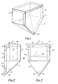
- Figure 1 is a perspective view of the apparatus;
- Figure 2 is a side elevation of the apparatus;
- Figure 3 is a front elevation of the apparatus; and
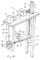
- Figure 4 is a perspective view of the jig on which the articles to be plated are suspended.
- The apparatus shown in the drawings, comprises a vessel or container 1 having a parallelepiped shaped
upper portion 2 and a downwardly taperinglower portion 3 in the form of an inverted pyramid which is skewed so that oneside face 4 forms a continuation of oneside face 5 of the upper portion. - The vessel 1 contains a
partition 6 which lies in a vertical plane parallel to the side faces 4 and 5 of the vessel and makes contact at its side edges 7 and 8 with the adjacent vertical and sloping faces of the vessel. The partition thus divides the vessel into alarger working zone 9 and asmaller return zone 11. At its bottom, thepartition 6 terminates at ahorizontal edge 12 above the bottom of the vessel to afford aninterconnection 13 between theworking zone 9 and thereturn zone 11. At its top, thepartition 6 terminates at ahorizontal edge 14 below the top edges of the vessel 1. - At the bottom of the
return zone 11 there is anair inlet 15 which is connected to an air pump (not shown). Mounted in theworking zone 9 is ajig 21 to which the workpiece to be coated are mounted, thejig 21 being arranged to move the workpieces within the vessel in a manner to be described in greater detail below. - When the apparatus is to be used for electrolytic plating, conductors are provided to apply a voltage to the workpiece mounted on the
jig 21 relative to an anode which is suspended in the working zone. - To use the apparatus, to codeposit a coating on the workpieces, the workpieces are mounted on the
jig 21 which is positioned in the vessel as shown. Before or after the positioning of the jig, the vessel is filled to alevel 17 above thetop edge 14 of thepartition 6 with a plating solution containing particles to be co-deposited. Air is admitted to theinlet 15 and this rises up thereturn zone 11, raising solution and entrained particles. At the top of the return zone, the air escapes and the solution and particles flow over the broad crested weir formed by thetop edge 14 of the partition and flow down past the workpieces on thejig 21. At the bottom of theworking zone 9, the particles tend to settle and slide down the inclined sides of the vessel towards theinterconnection 13 where they are again entrained in the solution and carried round again. - As the downwardly travelling particles in the
working zone 9 encounter the workpiece, they tend to settle on the workpiece where they become embedded in the metal which is being simultaneously plated out. - The workpieces to be coated are mounted on a
jig 21 shown in Figure 4 which is suspended in the vessel 1. The jig is shown in simplified form in Figures 2 and 3 but omitted from Figure 1 for reasons of clarity. Thejig 21 comprises adeck 22 which fits over the top of the vessel 1, a dependingpillar 23 towards one end and a pair of dependingguides 24 at the other end. Theguides 24 have facing guideways in which slides across-head 25 carrying avertical rack 26 which passes upwards through ahole 27 in thedeck 22 and meshes with apinion 28 driven by a reversibleelectric motor 29. Thedeck 22 supports a secondelectric motor 31 which drives avertical shaft 32 carrying abevel pinion 33 which engages a crown-wheel 34 fixed to one end of aspindle 35 mounted in thepillar 23. The other end of thespindle 35 is connected by auniversal joint 36 to one end of ashaft 37 the other end of which is carried by aspherical bearing 38 in thecross-head 25. - The
shaft 37 carries a plurality of spurs which are rigidly attached thereto, only onespur 39 being shown in Figure 4. Thespur 39 extends in a plane containing the axis of theshaft 37 with the longitudinal axis of the spur making an angle α with the axis of theshaft 37. Mounted on thespur 39 and spaced therealong are threegas turbine blades 42 to be coated, with the longitudinal axes of the blades extending in the said plane and perpendicular to the longitudinal axis of thespur 39 so that the longitudinal axes of the blades make angles of (90-α)° to the axis of theshaft 37. - An
electronic motor controller 43 is mounted on thedeck 22 and is connected bylines motors controller 43 is designed to drive themotor 29 in one direction only but with a stop so as to rotate theshaft 37 about a nominally horizontal axis (the x-axis). Thecontroller 43 is designed to drive themotor 31 alternately in opposite directions to reciprocate thecross-head 25 and so superimpose on the rotation about the x-axis an oscillatory rotation about a rotating axis in the universal joint 36 (the y-axis). - The angle α and the parameters of the cycles executed by the
motors - One particular class of composite coatings which may be produced by the apparatus described is that comprising a matrix of Ni, Co or NiCo with particles of CrAlY. It has been found that good quality coatings containing up to 30% by weight of particles can be produced using only 1 gram per litre of particles in the solution.
- One particular example of a coating and the method of production thereof will now be described by way of example.
- The coating is to be produced on a
gas turbine blade 42 having anaerofoil section 43 with aroot portion 44 at one end and ashroud portion 45 at the other end, the platforms of the root and shroud both extending at angles of approximately 70° to the axis of the aerofoil portion and the root portion and the shroud portion having end faces which extend at respectively 30° and 40° to the circumference of the ring of which the blade forms part. For blades of this geometry the angle α is 70°. - It is intended to produce on the aerofoil and platform portions of the blade a coating containing 18.32 weight percent Cr, 8.25 weight percent Al, 0.457 weight percent Y and the remainder cobalt. To produce such a coating the bath is filled with a cobalt plating solution comprising 400 grams per litre of CoSO₄.7H₂O, 15 grams per litre of NaCl and 20 grams per litre of boric acid H₃BO₃. The bath is maintained at a pH of 4.5 and a temperature of 45°C. The bath is loaded with powder to a concentration of 70 grams per litre, the powder having a size distribution of 5 to 15 micrometres and being composed of 67.8 weight percent chromium, 30.1 weight percent aluminium and 1.7 weight percent yttrium.
- Prior to coating the parts of the root and shroud portions which are not be plated are given a wax mask and the remaining surfaces are given the conventional preparation treatments appropriate to cobalt plating.
- The blade is fixed to the jig with its axis (see Figure 4) at 20° to the x axis of the jig which is horizontal. During plating the x axis of the jig is oscillated plus and minus 25° about the y axis which is perpendicular to the x axis with a cycle time of 3 minutes. Simultaneously, the jig is rotated about the x axis unidirectionally and through 360° with a cycle time of 10 minutes for a complete revolution. However the rotation about the x axis is intermittent with 10 second stop periods being interspersed with 3 second go periods.
- Plating is carried out with a current density of 0.3 amps per square decimetre for a period of 24 hours to produce a coating thickness of between 50 and 125 micrometres.
- A coating of excellent qualities is produced covering the aerofoil portion and the root and shroud platforms and having a weight fraction of incorporated powder of 0.27. After removal of the coated blades from the jig, the masking is removed and the blades are heat treated to effect some interdiffusion between the matrix and the particles and to effect some degree of alloying.
Claims (4)
- A process for the production of electrolytic or electroless deposition on a workpiece of a composite coating comprising a metal matrix containing particles, the particles being codeposited with the metal from a solution in which the particles are insoluble, comprising inducing circulation in the solution generally upwards in one zone and generally downwards in a second zone, locating the workpiece in the second zone, and rotating the workpiece about an axis having a horizontal component, characterised in that the rotational cycle includes periods of higher angular velocity and periods of lower angular velocity.
- A process according to Claim 1 in which the rotation is alternately stop and go.
- A process according to Claim 1 or Claim 2 in which the workpiece is also rotated about a second axis which is non-parallel with the first.
- A process for the production by electrolytic or electroless deposition on a workpiece of a composite coating comprising a metal matrix containing particles, the particles being codeposited with the metal from a solution in which the particles are insoluble, comprising inducing circulation in the solution generally upwards in one zone and generally downwards in a second zone, locating the workpiece in the second zone and rotating the workpiece about an axis having a horizontal component characterised in that the workpiece is also rotated about a second axis which is non-parallel with the first.
Applications Claiming Priority (2)
| Application Number | Priority Date | Filing Date | Title |
|---|---|---|---|
| GB888818069A GB8818069D0 (en) | 1988-07-29 | 1988-07-29 | Improvements relating to electrodeposited coatings |
| GB8818069 | 1988-07-29 |
Publications (3)
| Publication Number | Publication Date |
|---|---|
| EP0355051A2 EP0355051A2 (en) | 1990-02-21 |
| EP0355051A3 EP0355051A3 (en) | 1990-05-30 |
| EP0355051B1 true EP0355051B1 (en) | 1992-09-09 |
Family
ID=10641304
Family Applications (1)
| Application Number | Title | Priority Date | Filing Date |
|---|---|---|---|
| EP89307713A Expired EP0355051B1 (en) | 1988-07-29 | 1989-07-28 | Improvements relating to the production of coatings |
Country Status (7)
| Country | Link |
|---|---|
| US (1) | US5037513A (en) |
| EP (1) | EP0355051B1 (en) |
| JP (1) | JPH02138497A (en) |
| CA (1) | CA1338144C (en) |
| DE (1) | DE68902806T2 (en) |
| ES (1) | ES2035569T3 (en) |
| GB (2) | GB8818069D0 (en) |
Families Citing this family (19)
| Publication number | Priority date | Publication date | Assignee | Title |
|---|---|---|---|---|
| DE3815976A1 (en) * | 1988-05-10 | 1989-11-23 | Mtu Muenchen Gmbh | METHOD FOR PRODUCING GALVANICALLY SEPARATED HOT GAS CORROSION LAYERS |
| JPH04196395A (en) * | 1990-11-28 | 1992-07-16 | Hitachi Ltd | Electronic computer and cooling device thereof |
| US5674631A (en) * | 1993-01-19 | 1997-10-07 | Surface Technology, Inc. | Selective codeposition of particulate matter and composite plated articles thereof |
| US5702763A (en) * | 1993-01-19 | 1997-12-30 | Surface Technology, Inc. | Selective codeposition of particulate matter and composite plated articles thereof |
| GB9303853D0 (en) * | 1993-02-25 | 1993-04-21 | Baj Coatings Ltd | Rotor blades |
| GB9414859D0 (en) * | 1994-07-22 | 1994-09-14 | Baj Coatings Ltd | Protective coating |
| GB9414858D0 (en) * | 1994-07-22 | 1994-09-14 | Baj Coatings Ltd | Protective coating |
| US5935407A (en) * | 1997-11-06 | 1999-08-10 | Chromalloy Gas Turbine Corporation | Method for producing abrasive tips for gas turbine blades |
| FR2787472B1 (en) | 1998-12-16 | 2001-03-09 | Onera (Off Nat Aerospatiale) | PROCESS FOR PRODUCING A METAL ALLOY POWDER OF THE MCRALY TYPE AND COATINGS OBTAINED THEREWITH |
| EP1426458B1 (en) * | 2002-12-06 | 2008-03-12 | ALSTOM Technology Ltd | Method of locally depositing a MCrAlY coating |
| SG145591A1 (en) * | 2007-02-27 | 2008-09-29 | Turbine Overhaul Services Pte | System and method for electroplating metal components |
| JP4564545B2 (en) * | 2008-03-25 | 2010-10-20 | 株式会社東芝 | Coating method |
| FR2954780B1 (en) | 2009-12-29 | 2012-02-03 | Snecma | METHOD FOR THE ELECTROLYTIC DEPOSITION OF A METALLIC MATRIX COMPOSITE COATING CONTAINING PARTICLES FOR THE REPAIR OF A METAL BLADE |
| US8778164B2 (en) | 2010-12-16 | 2014-07-15 | Honeywell International Inc. | Methods for producing a high temperature oxidation resistant coating on superalloy substrates and the coated superalloy substrates thereby produced |
| US9771661B2 (en) | 2012-02-06 | 2017-09-26 | Honeywell International Inc. | Methods for producing a high temperature oxidation resistant MCrAlX coating on superalloy substrates |
| CN104099657A (en) * | 2014-06-25 | 2014-10-15 | 北京理工大学 | Preparation method of MCrAlY alloy coating layer |
| US9957629B2 (en) | 2014-08-27 | 2018-05-01 | Praxair S.T. Technology, Inc. | Electroplated coatings |
| US10087540B2 (en) | 2015-02-17 | 2018-10-02 | Honeywell International Inc. | Surface modifiers for ionic liquid aluminum electroplating solutions, processes for electroplating aluminum therefrom, and methods for producing an aluminum coating using the same |
| RU2655377C2 (en) * | 2015-12-15 | 2018-05-28 | Федеральное государственное унитарное предприятие "Центральный научно-исследовательский институт конструкционных материалов "Прометей" имени И.В. Горынина Национального исследовательского центра "Курчатовский институт" (НИЦ "Курчатовский институт" - ЦНИИ КМ "Прометей") | Multilayer magnetic and electromagnetic screen for protection against the radiation of power cables |
Family Cites Families (7)
| Publication number | Priority date | Publication date | Assignee | Title |
|---|---|---|---|---|
| US3830711A (en) * | 1972-01-19 | 1974-08-20 | Bristol Aerojet Ltd | Electrodeposition of composite coatings |
| US4305792A (en) * | 1977-12-21 | 1981-12-15 | Bristol Aerojet Limited | Processes for the electrodeposition of composite coatings |
| US4249998A (en) * | 1979-08-24 | 1981-02-10 | Kennecott Copper Corporation | Apparatus and process for producing copper-boron carbide composite by electrolytic entrapment |
| DE3003484A1 (en) * | 1980-01-31 | 1981-08-06 | VMEI Lenin, Sofia | Prodn. of abrasive surface, e.g. for a tool - by contacting surface with abrasive particles with simultaneous electroless deposition of nickel |
| DE3277378D1 (en) * | 1982-12-01 | 1987-10-29 | Ford Motor Co | Electrolytic codeposition of zinc and graphite and resulting product |
| FR2571386B1 (en) * | 1984-10-05 | 1990-01-12 | Baj Ltd | PROTECTIVE METAL COATINGS |
| GB2182055B (en) * | 1985-10-28 | 1989-10-18 | Baj Ltd | Improvements relating to electrodeposited coatings |
-
1988
- 1988-07-29 GB GB888818069A patent/GB8818069D0/en active Pending
-
1989
- 1989-07-28 CA CA000606896A patent/CA1338144C/en not_active Expired - Lifetime
- 1989-07-28 ES ES198989307713T patent/ES2035569T3/en not_active Expired - Lifetime
- 1989-07-28 EP EP89307713A patent/EP0355051B1/en not_active Expired
- 1989-07-28 DE DE8989307713T patent/DE68902806T2/en not_active Expired - Lifetime
- 1989-07-28 GB GB8917248A patent/GB2221921B/en not_active Expired - Lifetime
- 1989-07-29 JP JP1197913A patent/JPH02138497A/en active Granted
- 1989-07-31 US US07/387,074 patent/US5037513A/en not_active Expired - Lifetime
Also Published As
| Publication number | Publication date |
|---|---|
| US5037513A (en) | 1991-08-06 |
| GB2221921B (en) | 1993-02-03 |
| GB8818069D0 (en) | 1988-09-28 |
| EP0355051A2 (en) | 1990-02-21 |
| EP0355051A3 (en) | 1990-05-30 |
| GB2221921A (en) | 1990-02-21 |
| CA1338144C (en) | 1996-03-12 |
| DE68902806D1 (en) | 1992-10-15 |
| JPH02138497A (en) | 1990-05-28 |
| DE68902806T2 (en) | 1993-03-11 |
| GB8917248D0 (en) | 1989-09-13 |
| JPH0471998B2 (en) | 1992-11-17 |
| ES2035569T3 (en) | 1993-04-16 |
Similar Documents
| Publication | Publication Date | Title |
|---|---|---|
| EP0355051B1 (en) | Improvements relating to the production of coatings | |
| EP0724658B1 (en) | Protective coating | |
| CA2036904C (en) | Gas turbine blades | |
| US5824205A (en) | Protective coating | |
| US3061525A (en) | Method for electroforming and coating | |
| US4113549A (en) | Chemical milling process | |
| EP0612360B1 (en) | Electrodeposited composite coatings | |
| US5251409A (en) | Method of drag finishing a housing | |
| AU684263B2 (en) | Method of producing an abrasive tip on a turbine blade | |
| GB2254338A (en) | Electrolytic or electroless codeposition of particles and metal | |
| Foster | Electrolytic or electroless codeposition of particles and metal | |
| Foster | Production of Coatings |
Legal Events
| Date | Code | Title | Description |
|---|---|---|---|
| PUAI | Public reference made under article 153(3) epc to a published international application that has entered the european phase |
Free format text: ORIGINAL CODE: 0009012 |
|
| AK | Designated contracting states |
Kind code of ref document: A2 Designated state(s): BE DE ES FR GB IT NL SE |
|
| PUAL | Search report despatched |
Free format text: ORIGINAL CODE: 0009013 |
|
| AK | Designated contracting states |
Kind code of ref document: A3 Designated state(s): BE DE ES FR GB IT NL SE |
|
| RHK1 | Main classification (correction) |
Ipc: C25D 15/02 |
|
| 17P | Request for examination filed |
Effective date: 19901130 |
|
| 17Q | First examination report despatched |
Effective date: 19911211 |
|
| GRAA | (expected) grant |
Free format text: ORIGINAL CODE: 0009210 |
|
| ITF | It: translation for a ep patent filed |
Owner name: BARZANO' E ZANARDO ROMA S.P.A. |
|
| AK | Designated contracting states |
Kind code of ref document: B1 Designated state(s): BE DE ES FR GB IT NL SE |
|
| RBV | Designated contracting states (corrected) |
Designated state(s): BE DE ES FR IT NL SE |
|
| REF | Corresponds to: |
Ref document number: 68902806 Country of ref document: DE Date of ref document: 19921015 |
|
| ET | Fr: translation filed | ||
| REG | Reference to a national code |
Ref country code: ES Ref legal event code: FG2A Ref document number: 2035569 Country of ref document: ES Kind code of ref document: T3 |
|
| PLBE | No opposition filed within time limit |
Free format text: ORIGINAL CODE: 0009261 |
|
| STAA | Information on the status of an ep patent application or granted ep patent |
Free format text: STATUS: NO OPPOSITION FILED WITHIN TIME LIMIT |
|
| 26N | No opposition filed | ||
| EAL | Se: european patent in force in sweden |
Ref document number: 89307713.1 |
|
| REG | Reference to a national code |
Ref country code: FR Ref legal event code: CD |
|
| NLT1 | Nl: modifications of names registered in virtue of documents presented to the patent office pursuant to art. 16 a, paragraph 1 |
Owner name: BAJ COATINGS LIMITED |
|
| NLS | Nl: assignments of ep-patents |
Owner name: PRAXAIR S.T. TECHNOLOGY, INC. |
|
| BECA | Be: change of holder's address |
Free format text: 961010 *PRAXAIR ST TECHNOLOGY INC.:441 SACKETT POINT ROAD, NORTH HAVEN CT 06473 |
|
| BECH | Be: change of holder |
Free format text: 961010 *PRAXAIR ST TECHNOLOGY INC. |
|
| REG | Reference to a national code |
Ref country code: FR Ref legal event code: TP |
|
| PGFP | Annual fee paid to national office [announced via postgrant information from national office to epo] |
Ref country code: ES Payment date: 20080728 Year of fee payment: 20 Ref country code: DE Payment date: 20080829 Year of fee payment: 20 |
|
| PGFP | Annual fee paid to national office [announced via postgrant information from national office to epo] |
Ref country code: FR Payment date: 20080729 Year of fee payment: 20 Ref country code: NL Payment date: 20080724 Year of fee payment: 20 Ref country code: IT Payment date: 20080728 Year of fee payment: 20 |
|
| PGFP | Annual fee paid to national office [announced via postgrant information from national office to epo] |
Ref country code: BE Payment date: 20080818 Year of fee payment: 20 Ref country code: SE Payment date: 20080729 Year of fee payment: 20 |
|
| EUG | Se: european patent has lapsed | ||
| REG | Reference to a national code |
Ref country code: ES Ref legal event code: FD2A Effective date: 20090729 |
|
| NLV7 | Nl: ceased due to reaching the maximum lifetime of a patent |
Effective date: 20090728 |
|
| PG25 | Lapsed in a contracting state [announced via postgrant information from national office to epo] |
Ref country code: ES Free format text: LAPSE BECAUSE OF EXPIRATION OF PROTECTION Effective date: 20090729 |
|
| PG25 | Lapsed in a contracting state [announced via postgrant information from national office to epo] |
Ref country code: NL Free format text: LAPSE BECAUSE OF EXPIRATION OF PROTECTION Effective date: 20090728 |