EP0354975B1 - Commodity meters - Google Patents
Commodity meters Download PDFInfo
- Publication number
- EP0354975B1 EP0354975B1 EP19880307584 EP88307584A EP0354975B1 EP 0354975 B1 EP0354975 B1 EP 0354975B1 EP 19880307584 EP19880307584 EP 19880307584 EP 88307584 A EP88307584 A EP 88307584A EP 0354975 B1 EP0354975 B1 EP 0354975B1
- Authority
- EP
- European Patent Office
- Prior art keywords
- valve
- credit
- solenoid
- signal
- commodity
- Prior art date
- Legal status (The legal status is an assumption and is not a legal conclusion. Google has not performed a legal analysis and makes no representation as to the accuracy of the status listed.)
- Expired - Lifetime
Links
- 230000004044 response Effects 0.000 claims description 2
- 230000004907 flux Effects 0.000 description 3
- 239000003990 capacitor Substances 0.000 description 1
- 239000011435 rock Substances 0.000 description 1
- 230000015607 signal release Effects 0.000 description 1
Images

Classifications
-
- B—PERFORMING OPERATIONS; TRANSPORTING
- B67—OPENING, CLOSING OR CLEANING BOTTLES, JARS OR SIMILAR CONTAINERS; LIQUID HANDLING
- B67D—DISPENSING, DELIVERING OR TRANSFERRING LIQUIDS, NOT OTHERWISE PROVIDED FOR
- B67D7/00—Apparatus or devices for transferring liquids from bulk storage containers or reservoirs into vehicles or into portable containers, e.g. for retail sale purposes
- B67D7/06—Details or accessories
- B67D7/08—Arrangements of devices for controlling, indicating, metering or registering quantity or price of liquid transferred
- B67D7/30—Arrangements of devices for controlling, indicating, metering or registering quantity or price of liquid transferred with means for predetermining quantity of liquid to be transferred
- B67D7/305—Arrangements of devices for controlling, indicating, metering or registering quantity or price of liquid transferred with means for predetermining quantity of liquid to be transferred in function of money to be spent therefor
-
- G—PHYSICS
- G07—CHECKING-DEVICES
- G07F—COIN-FREED OR LIKE APPARATUS
- G07F15/00—Coin-freed apparatus with meter-controlled dispensing of liquid, gas or electricity
- G07F15/001—Coin-freed apparatus with meter-controlled dispensing of liquid, gas or electricity for gas
-
- G—PHYSICS
- G07—CHECKING-DEVICES
- G07F—COIN-FREED OR LIKE APPARATUS
- G07F17/00—Coin-freed apparatus for hiring articles; Coin-freed facilities or services
- G07F17/0014—Coin-freed apparatus for hiring articles; Coin-freed facilities or services for vending, access and use of specific services not covered anywhere else in G07F17/00
-
- G—PHYSICS
- G07—CHECKING-DEVICES
- G07F—COIN-FREED OR LIKE APPARATUS
- G07F5/00—Coin-actuated mechanisms; Interlocks
- G07F5/20—Coin-actuated mechanisms; Interlocks specially adapted for registering coins as credit, e.g. mechanically actuated
Definitions
- This invention relates to commodity meters through which a flowing commodity is supplied, the meter measuring the volume of commodity for payment or other purposes.
- Such meters have commonly been arranged as prepayment meters into which coins are inserted, thus freeing the meter to supply a specific volume of the commodity.
- Such meters are liable to attempts at theft of the money in them and efforts have been made to meet this problem by replacing the coins with tokens of negligible intrinsic value.
- meters using tokens are liable to attempts to avoid payment.
- GB-A-2144566 discloses a metering apparatus arranged to operate on a prepayment system, having metering elements and a contactor arranged to control the availability of a commodity, and a separate token operated device adapted to control the opening and closing of the contractor.
- a prepayment system having metering elements and a contactor arranged to control the availability of a commodity, and a separate token operated device adapted to control the opening and closing of the contractor.
- CA-A-963577 discloses the use of a valve from controlling the availability of a commodity.
- This invention provides a metering apparatus for a flowing commodity of the kind arranged to operate on a prepayment system, having metering elements enclosed in a casing, valve means located in the same casing in the flow path of the commodity so as to control the availability of the commodity, a separate token-operated device adapted to provide an electrical credit signal to credit storage means, which credit storage means controls the opening and closing of the valve means and an electrical connection extending between the token-operated device and the casing, characterized by sensing means for sensing tampering or damage to the apparatus, the sensing means being adapted to provide a 'valve close' signal, and by electrical drive means for said valve means arranged to cause the valve to close in response to both a zero credit signal and a 'valve close' signal produced when tampering or damage is sensed.
- the electrical drive means includes an electric motor and a self-holding solenoid, said solenoid having a release circuit which is adapted to be operated by a zero credit signal and when damage to the said connection
- the credit storage means may comprise an electronic memory controlling the electrical drive means which opens and closes the valve means.
- the memory receives data from the metering elements which progessively reduces the credit recorded in the memory until at zero credit the valve means is caused to close.
- the commodity meter is a gas meter.
- a gas meter 11 is of the kind comprising flexible diaphragms driven back-and-forth by flowing gas, which is of proven accuracy and reliability.
- the meter has a mechanical counter mechanism of conventional kind providing a read-out of the measured volume of gas which has passed through the meter, and also has means for providing an electrical reproduction of the read-out, either as a series of electrical pulses or as a coded representation of the number. Suitable examples of such means are described in our patent specification GB-A-2187010 and GB-A-2187011.
- Valve 14 Located in a main gas flow path through the meter is an on/off valve 14. Valve 14 is located in the same meter casing as the metering elements.
- a card reader and eraser unit 30 is located at a position convenient to a user and may be remote from the gas meter 11. It is connected to the meter 11 by a multicore cable 21.
- the unit has a slot into which a gas card may be manually inserted.
- the gas card carries a magnetic code relating to its face value.
- the unit 30 When the unit 30 has read the card, it erases the magnetic code so that the card cannot be used again.
- the magnetically coded gas cards may be purchased at appropriate retail outlets, and discarded when used. Alternatively, the same card may be re-activated at the retail outlet on payment of the face value. Thus there is nothing to be collected from the meter, neither money nor token.
- the apparatus described has a high degree of inbuilt security against fraud.
- the valve 14 will close when the device is tampered with or when the prepaid gas is used up and all that will happen is that the user is unable to insert more credit into the meter.
- the valve 14 being mounted inside the meter has the same degree of security as the meter index.
- the valve 14 is driven to an open position by a DC motor 40 mounted on the outer surface of the meter.
- a gas card is inserted into the unit 30, the face value is read and transferred to an electronic credit storage unit 41 which is also mounted inside the unit 30.
- a signal to motor 40 causes it to open valve 14.
- the meter 11 produces electrical pulses which are sensed by the credit storage unit 41 and subtracted from the credit stored.
- another signal releases a solenoid 42 to close valve 14 as described hereinafter.
- both the card reading unit 30 and the meter have their own replaceable dry batteries 34 and 34′.
- the DC motor 40 drives cam 44 through a gear train 45.
- a roller 46 mounted on a pivoted cradle 47 runs on the cam so that cradle 47 rocks.
- a shaft 48 is secured at one end to a closure member 49 of the gas valve 14 within the meter and extends out through the wall of the meter (not shown) to extend freely through bearings in the cradle 47.
- a lever 50 is secured at one end to rotate with the shaft 48 and at the other end carries an armature 51 which co-operates with solenoid 42.
- a valve closing spring 52 is urging the lever 50 upwards so as to rotate shaft 48 in the sense to maintain the gas valve 14 in the closed position.
- Solenoid 42 is of the 'self holding' type, incorporating a permanent magnet strong enough to hold the valve open, but also having means for producing a flux in opposition to the holding flux which thus cancels it and releases the armature 51.
- the 'release' signal is produced on the occurrence of several different situations. The main one is of course when the credit in storage unit 41 runs out, but it is also used for safety features. In the event of tampering with the gas meter, for instance tilting or cutting of the electrical connection wire 21, or tampering with the card reading and erasing unit 30, a 'release' signal is produced which causes the valve to close. It will be noted that the release will work even whilst credit has been added and the motor is opening the valve.
- the battery 34′ may be a long life, high density primary cell or a rechargeable battery or a low leakage capacitor charged by external means.
- the apparatus can incorporate an emergency supply system in which the user is allowed a limited free supply on demand, payment for which is then deducted from the next credit input.
- This may be provided by a button-operated circuit in the card reader 3C, which provides one only free credit input to the motor and then deducts the same credit from the next card inserted.
- this is provided by a special memory section of the credit store 41 which provides one only free credit and then deducts this from the next input from the card reader 30.
- valve 14 is driven to open and shut positions by the same DC motor under the control of the credit storage unit.
- the motor and credit storage unit may be mounted within the meter casing.
Landscapes
- Physics & Mathematics (AREA)
- General Physics & Mathematics (AREA)
- Engineering & Computer Science (AREA)
- Mathematical Physics (AREA)
- Theoretical Computer Science (AREA)
- Mechanical Engineering (AREA)
- Beverage Vending Machines With Cups, And Gas Or Electricity Vending Machines (AREA)
- Measuring Volume Flow (AREA)
Description
- This invention relates to commodity meters through which a flowing commodity is supplied, the meter measuring the volume of commodity for payment or other purposes.
- Such meters have commonly been arranged as prepayment meters into which coins are inserted, thus freeing the meter to supply a specific volume of the commodity. Such meters are liable to attempts at theft of the money in them and efforts have been made to meet this problem by replacing the coins with tokens of negligible intrinsic value. However, meters using tokens are liable to attempts to avoid payment.
- Specification GB-A-2144566 discloses a metering apparatus arranged to operate on a prepayment system, having metering elements and a contactor arranged to control the availability of a commodity, and a separate token operated device adapted to control the opening and closing of the contractor. However there is no security against tampering.
- Specification CA-A-963577 discloses the use of a valve from controlling the availability of a commodity.
- This invention provides a metering apparatus for a flowing commodity of the kind arranged to operate on a prepayment system, having metering elements enclosed in a casing, valve means located in the same casing in the flow path of the commodity so as to control the availability of the commodity, a separate token-operated device adapted to provide an electrical credit signal to credit storage means, which credit storage means controls the opening and closing of the valve means and an electrical connection extending between the token-operated device and the casing, characterized by sensing means for sensing tampering or damage to the apparatus, the sensing means being adapted to provide a 'valve close' signal, and by electrical drive means for said valve means arranged to cause the valve to close in response to both a zero credit signal and a 'valve close' signal produced when tampering or damage is sensed. Preferably the electrical drive means includes an electric motor and a self-holding solenoid, said solenoid having a release circuit which is adapted to be operated by a zero credit signal and when damage to the said connection is sensed.
- The credit storage means may comprise an electronic memory controlling the electrical drive means which opens and closes the valve means. The memory receives data from the metering elements which progessively reduces the credit recorded in the memory until at zero credit the valve means is caused to close.
- By using an internal valve means with an external token-operated device it is found that a higher degree of security can be achieved than at first appears. Attempts to interfere with the device simply stop further credit being inserted without causing the valve means to stay open.
- Preferably the commodity meter is a gas meter.
- One embodiment of the invention will now be described, by way of example, with reference to the accompanying drawings, in which:-
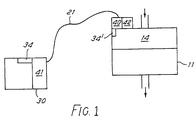
- Figure 1 comprises a representation of a token-operated gas metering apparatus, and
- Figure 2 is a three dimension representation of part of the apparatus of Figure 1.
- A
gas meter 11 is of the kind comprising flexible diaphragms driven back-and-forth by flowing gas, which is of proven accuracy and reliability. The meter has a mechanical counter mechanism of conventional kind providing a read-out of the measured volume of gas which has passed through the meter, and also has means for providing an electrical reproduction of the read-out, either as a series of electrical pulses or as a coded representation of the number. Suitable examples of such means are described in our patent specification GB-A-2187010 and GB-A-2187011. - Located in a main gas flow path through the meter is an on/off
valve 14. Valve 14 is located in the same meter casing as the metering elements. - A card reader and
eraser unit 30 is located at a position convenient to a user and may be remote from thegas meter 11. It is connected to themeter 11 by amulticore cable 21. The unit has a slot into which a gas card may be manually inserted. The gas card carries a magnetic code relating to its face value. - When the
unit 30 has read the card, it erases the magnetic code so that the card cannot be used again. The magnetically coded gas cards may be purchased at appropriate retail outlets, and discarded when used. Alternatively, the same card may be re-activated at the retail outlet on payment of the face value. Thus there is nothing to be collected from the meter, neither money nor token. - The apparatus described has a high degree of inbuilt security against fraud. The
valve 14 will close when the device is tampered with or when the prepaid gas is used up and all that will happen is that the user is unable to insert more credit into the meter. Thevalve 14 being mounted inside the meter has the same degree of security as the meter index. Thevalve 14 is driven to an open position by aDC motor 40 mounted on the outer surface of the meter. When a gas card is inserted into theunit 30, the face value is read and transferred to an electroniccredit storage unit 41 which is also mounted inside theunit 30. When credit is thus established, a signal to motor 40 causes it to openvalve 14. As the gas is used, themeter 11 produces electrical pulses which are sensed by thecredit storage unit 41 and subtracted from the credit stored. When the credit has returned to zero, another signal releases asolenoid 42 to closevalve 14 as described hereinafter. In this arrangement, both thecard reading unit 30 and the meter have their own replaceabledry batteries - Referring now to the detail of Figure 2, the
DC motor 40 drivescam 44 through agear train 45. Aroller 46 mounted on apivoted cradle 47 runs on the cam so thatcradle 47 rocks. Ashaft 48 is secured at one end to aclosure member 49 of thegas valve 14 within the meter and extends out through the wall of the meter (not shown) to extend freely through bearings in thecradle 47. Alever 50 is secured at one end to rotate with theshaft 48 and at the other end carries anarmature 51 which co-operates withsolenoid 42. As shown in full lines in the Figure, avalve closing spring 52 is urging thelever 50 upwards so as to rotateshaft 48 in the sense to maintain thegas valve 14 in the closed position. In order for the valve to be opened,armature 51 must take up the position shown in dotted lines. Solenoid 42 is of the 'self holding' type, incorporating a permanent magnet strong enough to hold the valve open, but also having means for producing a flux in opposition to the holding flux which thus cancels it and releases thearmature 51. - When credit is established in
storage unit 41 an electrical signal actuatesmotor 40. This drivescam 44, rockingcradle 47 first to raisesolenoid 42 from the position shown in dotted lines until it contactsarmature 51. The permanent magnet then carries the armature down as the solenoid returns to the position shown in dotted lines, thus opening the valve. Thecam 44 rotates untilhoming microswitch 53 is operated, indicating that the cam has completed a full circle, at whichpoint motor 40 ceases to operate. The valve then remains open until an electrical 'release' signal is received by the opposition flux circuit of thesolenoid 42. This releases thearmature 51 so thatspring 52 can liftlever 50 and close the valve. On cessation of the release signal, thearmature 51 is too far distant from the solenoid for the holding magnet to attract it against the spring force. Thus the valve can only be opened whencam 44 again rotates and liftssolenoid 42 into close proximity to thearmature 51. - The 'release' signal is produced on the occurrence of several different situations. The main one is of course when the credit in
storage unit 41 runs out, but it is also used for safety features. In the event of tampering with the gas meter, for instance tilting or cutting of theelectrical connection wire 21, or tampering with the card reading and erasingunit 30, a 'release' signal is produced which causes the valve to close. It will be noted that the release will work even whilst credit has been added and the motor is opening the valve. - The
battery 34′ may be a long life, high density primary cell or a rechargeable battery or a low leakage capacitor charged by external means. - Although a gas card with magnetic information is described above, it is within the invention to use other tokens for inserting credit. For instance, rechargeable tokens each incorporating a micro-processor which can be programmed to represent any credit sum desired may be used.
- The apparatus can incorporate an emergency supply system in which the user is allowed a limited free supply on demand, payment for which is then deducted from the next credit input. This may be provided by a button-operated circuit in the card reader 3C, which provides one only free credit input to the motor and then deducts the same credit from the next card inserted. Alternatively, this is provided by a special memory section of the
credit store 41 which provides one only free credit and then deducts this from the next input from thecard reader 30. - In another apparatus (not shown) the
valve 14 is driven to open and shut positions by the same DC motor under the control of the credit storage unit. The motor and credit storage unit may be mounted within the meter casing. - Although the invention has been described in relation to gas meters, it may be used in any other kind of meter in which a flowing commodity is controlled by a valve.
Claims (6)
- A metering apparatus for a flowing commodity of the kind arranged to operate on a prepayment system, having metering elements enclosed in a casing, valve means (14) located in the same casing in the flow path of the commodity so as to control the availability of the commodity, a separate token-operated device (30) adapted to provide an electrical credit signal to credit storage means (41), which credit storage means controls the opening and closing of the valve means (14) and an electrical connection (21) extending between the token-operated device and the casing, characterized by sensing means for sensing tampering or damage to the apparatus, the sensing means being adapted to provide a 'valve close' signal, and by electrical drive means (40) for said valve means (14) arranged to cause the valve to close in response to both a zero credit signal and a 'valve close' signal produced when tampering or damage is sensed.
- A metering apparatus according to claim 1 characterized in that the electrical drive means includes an electric motor (40) and a self-holding solenoid (42), said solenoid having a release circuit which is adapted to be operated by a zero credit signal and when damage to the said connection (21) is sensed.
- A metering apparatus as claimed in claim 2, further characterized in that said motor (40) is arranged to move the solenoid (42) in the sense to cause the solenoid to hold the valve means (14) open, while said release circuit, when energized causes the solenoid to release the valve means so that it returns to a closed position.
- A metering apparatus as claimed in any of claims 1 to 3, further characterized by the credit storage means comprising an electronic memory (41).
- A metering apparatus as claimed in any of claims 1 to 4 characterized in that the electric motor (40) is located in the casing.
- A metering apparatus as claimed in any of claims 1 to 5 characterized in that it is a gas meter.
Priority Applications (1)
| Application Number | Priority Date | Filing Date | Title |
|---|---|---|---|
| DE19883852639 DE3852639T2 (en) | 1988-08-16 | 1988-08-16 | Consumption meter. |
Applications Claiming Priority (1)
| Application Number | Priority Date | Filing Date | Title |
|---|---|---|---|
| GB878716987A GB8716987D0 (en) | 1987-07-18 | 1987-07-18 | Commodity meters |
Publications (2)
| Publication Number | Publication Date |
|---|---|
| EP0354975A1 EP0354975A1 (en) | 1990-02-21 |
| EP0354975B1 true EP0354975B1 (en) | 1994-12-28 |
Family
ID=10620884
Family Applications (1)
| Application Number | Title | Priority Date | Filing Date |
|---|---|---|---|
| EP19880307584 Expired - Lifetime EP0354975B1 (en) | 1987-07-18 | 1988-08-16 | Commodity meters |
Country Status (3)
| Country | Link |
|---|---|
| EP (1) | EP0354975B1 (en) |
| GB (2) | GB8716987D0 (en) |
| HK (1) | HK79191A (en) |
Cited By (2)
| Publication number | Priority date | Publication date | Assignee | Title |
|---|---|---|---|---|
| EP0545550A1 (en) * | 1991-11-30 | 1993-06-09 | Schlumberger Industries Limited | Prepayment water supply systems |
| EP0811957A2 (en) | 1996-06-05 | 1997-12-10 | Landis & Gyr Technology Innovation AG | Method for paying products and services |
Families Citing this family (7)
| Publication number | Priority date | Publication date | Assignee | Title |
|---|---|---|---|---|
| GB8716987D0 (en) * | 1987-07-18 | 1987-08-26 | Smith Meters Ltd | Commodity meters |
| GB8920446D0 (en) * | 1989-09-09 | 1989-10-25 | Schlumberger Ind Ltd | Electricity metering systems |
| FR2665504A1 (en) * | 1990-08-01 | 1992-02-07 | Tilhet Daniel | System for enabling the operation of a controlled element, especially of a solenoid valve for dispensing flushing water |
| GB9121759D0 (en) * | 1991-10-14 | 1991-11-27 | Philips Electronic Associated | Communications receiver |
| GB2305252B (en) * | 1995-09-12 | 1999-04-28 | Siemens Measurements Ltd | Improvements in or relating to gas meters |
| EP0843287B8 (en) * | 1996-11-16 | 2006-05-10 | Landis+Gyr Limited | Improvements in or relating to modular gas meters |
| GB9623844D0 (en) * | 1996-11-16 | 1997-01-08 | Siemens Measurements Ltd | Improvements in or relating to modular gas meters |
Family Cites Families (15)
| Publication number | Priority date | Publication date | Assignee | Title |
|---|---|---|---|---|
| FR1278675A (en) * | 1960-11-02 | 1961-12-15 | Th Pernin & Fils | Liquid distribution installation, in particular domestic fuel oil |
| US3254749A (en) * | 1961-03-03 | 1966-06-07 | Scherer Albert | Automatic self-service mechanisms for dispensing merchandise, for example, fuel and/or oil and grease for motor vehicles |
| GB1204111A (en) * | 1966-05-26 | 1970-09-03 | London Electricity Board | Improvements in or relating to consumers electric supply meters |
| DE2037580A1 (en) * | 1970-07-29 | 1972-02-03 | J. Hengstler Kg, 7207 Aldingen | Device for controlling a self-operated goods dispensing device by means of identification data carriers |
| US3778637A (en) * | 1971-06-18 | 1973-12-11 | K Arita | Apparatus for supplying a predetermined quantity of electric power |
| US3786421A (en) * | 1972-05-25 | 1974-01-15 | Atlantic Richfield Co | Automated dispensing system |
| CA963577A (en) * | 1972-12-20 | 1975-02-25 | Alfred L. Martin | Liquid dispensing machine |
| EP0063893B1 (en) * | 1981-04-21 | 1988-06-29 | Mainmet Limited | Energy controller |
| DE3373231D1 (en) * | 1983-01-18 | 1987-10-01 | Atlantic Richfield Co | System for use in gasoline station or the like for monitoring and controlling fuel dispensers |
| GB2144566A (en) * | 1983-08-05 | 1985-03-06 | Hawker Siddeley Revenue Contr | Remote metering system |
| CH653789A5 (en) * | 1983-09-09 | 1986-01-15 | Gatoil Suisse S A | INSTALLATION FOR AUTOMATIC PREPAYMENT FUEL. |
| GB8400809D0 (en) * | 1984-01-12 | 1984-02-15 | De La Rue Co Plc | Prepayment metering system |
| CH664226A5 (en) * | 1984-12-20 | 1988-02-15 | Landis & Gyr Ag | CASH PAYER FOR CASH-FREE PURCHASE OF ELECTRICAL ENERGY BY PRE-PAID VALUE CARDS. |
| US4731575A (en) * | 1986-12-08 | 1988-03-15 | Sloan Joseph W | Prepayment metering system using encoded purchase cards |
| GB8716987D0 (en) * | 1987-07-18 | 1987-08-26 | Smith Meters Ltd | Commodity meters |
-
1987
- 1987-07-18 GB GB878716987A patent/GB8716987D0/en active Pending
-
1988
- 1988-07-07 GB GB8816236A patent/GB2207269B/en not_active Expired - Lifetime
- 1988-08-16 EP EP19880307584 patent/EP0354975B1/en not_active Expired - Lifetime
-
1991
- 1991-10-10 HK HK79191A patent/HK79191A/en not_active IP Right Cessation
Cited By (2)
| Publication number | Priority date | Publication date | Assignee | Title |
|---|---|---|---|---|
| EP0545550A1 (en) * | 1991-11-30 | 1993-06-09 | Schlumberger Industries Limited | Prepayment water supply systems |
| EP0811957A2 (en) | 1996-06-05 | 1997-12-10 | Landis & Gyr Technology Innovation AG | Method for paying products and services |
Also Published As
| Publication number | Publication date |
|---|---|
| GB8816236D0 (en) | 1988-08-10 |
| HK79191A (en) | 1991-10-18 |
| GB8716987D0 (en) | 1987-08-26 |
| GB2207269A (en) | 1989-01-25 |
| EP0354975A1 (en) | 1990-02-21 |
| GB2207269B (en) | 1991-05-29 |
Similar Documents
| Publication | Publication Date | Title |
|---|---|---|
| US4240030A (en) | Intelligent electric utility meter | |
| IE46313B1 (en) | Amusement with prizes machines | |
| EP0152198B1 (en) | A prepayment system | |
| PL218637B1 (en) | Pre-paid system for the supply of water or gas based on wireless smart card and a counter for this system | |
| EP0680646A1 (en) | Methods and apparatus for magnetically storing and retrieving credit card transaction information | |
| DK0570692T3 (en) | Coin Payment Machine | |
| EP0354975A1 (en) | Commodity meters | |
| GB1356425A (en) | Dispensing appliances | |
| WO1996003721A1 (en) | Apparatus for metering and dispensing gas | |
| WO1999042963A1 (en) | Apparatus for prepayment water management | |
| EP0545550B1 (en) | Prepayment water supply systems | |
| GB2260011B (en) | Prepayment systems | |
| EP0576276B1 (en) | Prepayment water supply system | |
| KR100805847B1 (en) | Ic chip read-write device | |
| US3921875A (en) | Control device | |
| DE3852639T2 (en) | Consumption meter. | |
| EP0545549A1 (en) | Prepayment systems | |
| JP4313994B2 (en) | Game media lending machine | |
| GB2295443A (en) | Metering apparatus | |
| GB2268302A (en) | Prepayment water supply systems | |
| JP4717948B2 (en) | Medals lending machine | |
| JPH0313912B2 (en) | ||
| JP4004580B2 (en) | Ball counter and ball counter system | |
| JPH0126221B2 (en) | ||
| JP5075156B2 (en) | Game media lending machine |
Legal Events
| Date | Code | Title | Description |
|---|---|---|---|
| PUAI | Public reference made under article 153(3) epc to a published international application that has entered the european phase |
Free format text: ORIGINAL CODE: 0009012 |
|
| AK | Designated contracting states |
Kind code of ref document: A1 Designated state(s): BE DE FR IT NL |
|
| 17P | Request for examination filed |
Effective date: 19900503 |
|
| 17Q | First examination report despatched |
Effective date: 19920610 |
|
| GRAA | (expected) grant |
Free format text: ORIGINAL CODE: 0009210 |
|
| REF | Corresponds to: |
Ref document number: 3852639 Country of ref document: DE Date of ref document: 19950209 |
|
| ITF | It: translation for a ep patent filed | ||
| ET | Fr: translation filed | ||
| PLBE | No opposition filed within time limit |
Free format text: ORIGINAL CODE: 0009261 |
|
| STAA | Information on the status of an ep patent application or granted ep patent |
Free format text: STATUS: NO OPPOSITION FILED WITHIN TIME LIMIT |
|
| 26N | No opposition filed | ||
| PGFP | Annual fee paid to national office [announced via postgrant information from national office to epo] |
Ref country code: BE Payment date: 20000823 Year of fee payment: 13 |
|
| PGFP | Annual fee paid to national office [announced via postgrant information from national office to epo] |
Ref country code: FR Payment date: 20000824 Year of fee payment: 13 |
|
| PGFP | Annual fee paid to national office [announced via postgrant information from national office to epo] |
Ref country code: DE Payment date: 20000825 Year of fee payment: 13 |
|
| PGFP | Annual fee paid to national office [announced via postgrant information from national office to epo] |
Ref country code: NL Payment date: 20000831 Year of fee payment: 13 |
|
| PG25 | Lapsed in a contracting state [announced via postgrant information from national office to epo] |
Ref country code: BE Free format text: LAPSE BECAUSE OF NON-PAYMENT OF DUE FEES Effective date: 20010831 |
|
| BERE | Be: lapsed |
Owner name: SMITH METERS LTD Effective date: 20010831 |
|
| PG25 | Lapsed in a contracting state [announced via postgrant information from national office to epo] |
Ref country code: NL Free format text: LAPSE BECAUSE OF NON-PAYMENT OF DUE FEES Effective date: 20020301 |
|
| PG25 | Lapsed in a contracting state [announced via postgrant information from national office to epo] |
Ref country code: FR Free format text: LAPSE BECAUSE OF NON-PAYMENT OF DUE FEES Effective date: 20020430 |
|
| NLV4 | Nl: lapsed or anulled due to non-payment of the annual fee |
Effective date: 20020301 |
|
| PG25 | Lapsed in a contracting state [announced via postgrant information from national office to epo] |
Ref country code: DE Free format text: LAPSE BECAUSE OF NON-PAYMENT OF DUE FEES Effective date: 20020501 |
|
| REG | Reference to a national code |
Ref country code: FR Ref legal event code: ST |
|
| PG25 | Lapsed in a contracting state [announced via postgrant information from national office to epo] |
Ref country code: IT Free format text: LAPSE BECAUSE OF NON-PAYMENT OF DUE FEES;WARNING: LAPSES OF ITALIAN PATENTS WITH EFFECTIVE DATE BEFORE 2007 MAY HAVE OCCURRED AT ANY TIME BEFORE 2007. THE CORRECT EFFECTIVE DATE MAY BE DIFFERENT FROM THE ONE RECORDED. Effective date: 20050816 |