EP0354918B1 - Injector for implanting multiple pellet medicaments - Google Patents
Injector for implanting multiple pellet medicaments Download PDFInfo
- Publication number
- EP0354918B1 EP0354918B1 EP88903645A EP88903645A EP0354918B1 EP 0354918 B1 EP0354918 B1 EP 0354918B1 EP 88903645 A EP88903645 A EP 88903645A EP 88903645 A EP88903645 A EP 88903645A EP 0354918 B1 EP0354918 B1 EP 0354918B1
- Authority
- EP
- European Patent Office
- Prior art keywords
- obturator
- hub
- section
- distal
- proximal
- Prior art date
- Legal status (The legal status is an assumption and is not a legal conclusion. Google has not performed a legal analysis and makes no representation as to the accuracy of the status listed.)
- Expired - Lifetime
Links
- 239000008188 pellet Substances 0.000 title abstract description 26
- 239000003814 drug Substances 0.000 title description 13
- 239000007943 implant Substances 0.000 claims description 64
- 238000003780 insertion Methods 0.000 claims description 2
- 230000037431 insertion Effects 0.000 claims description 2
- 239000004033 plastic Substances 0.000 claims description 2
- 239000002184 metal Substances 0.000 claims 2
- 238000002513 implantation Methods 0.000 abstract description 15
- 238000000034 method Methods 0.000 abstract description 14
- 210000003813 thumb Anatomy 0.000 abstract description 10
- 238000007920 subcutaneous administration Methods 0.000 abstract description 8
- 239000007787 solid Substances 0.000 abstract description 2
- 229940079593 drug Drugs 0.000 description 9
- 239000003433 contraceptive agent Substances 0.000 description 6
- 230000002254 contraceptive effect Effects 0.000 description 6
- 239000000463 material Substances 0.000 description 6
- 230000008901 benefit Effects 0.000 description 4
- 210000003811 finger Anatomy 0.000 description 3
- 230000007774 longterm Effects 0.000 description 2
- 206010071368 Psychological trauma Diseases 0.000 description 1
- 210000001124 body fluid Anatomy 0.000 description 1
- 239000010839 body fluid Substances 0.000 description 1
- 238000004090 dissolution Methods 0.000 description 1
- 238000012377 drug delivery Methods 0.000 description 1
- 230000036512 infertility Effects 0.000 description 1
- 238000001746 injection moulding Methods 0.000 description 1
- 208000014674 injury Diseases 0.000 description 1
- 238000001990 intravenous administration Methods 0.000 description 1
- 239000002991 molded plastic Substances 0.000 description 1
- 229920000642 polymer Polymers 0.000 description 1
- 230000001012 protector Effects 0.000 description 1
- 230000002040 relaxant effect Effects 0.000 description 1
- 150000003431 steroids Chemical class 0.000 description 1
- 238000001356 surgical procedure Methods 0.000 description 1
- 229910000811 surgical stainless steel Inorganic materials 0.000 description 1
- 230000008733 trauma Effects 0.000 description 1
Images


Classifications
-
- A—HUMAN NECESSITIES
- A61—MEDICAL OR VETERINARY SCIENCE; HYGIENE
- A61M—DEVICES FOR INTRODUCING MEDIA INTO, OR ONTO, THE BODY; DEVICES FOR TRANSDUCING BODY MEDIA OR FOR TAKING MEDIA FROM THE BODY; DEVICES FOR PRODUCING OR ENDING SLEEP OR STUPOR
- A61M37/00—Other apparatus for introducing media into the body; Percutany, i.e. introducing medicines into the body by diffusion through the skin
- A61M37/0069—Devices for implanting pellets, e.g. markers or solid medicaments
Definitions
- One method of administering medicines is by subcutaneously implanting a medicinal pellet.
- this form of administration of drugs was not widely used.
- materials have been developed which allow a drug to be subcutaneously introduced or administered beneath the skin of a patient so that the drug is slowly released over a long period of time.
- Such implants allow a drug to be dispensed in a relatively uniform dose over many months or years.
- This method of administering drugs is becoming especially important and popular as a method of administering contraceptive implants.
- While subcutaneous implantation may be done surgically using a scalpel to make the incision and a trocar and cannula to place the implant, such methods require a physician or other highly trained person.
- improved instruments for implanting subcutaneous medicaments have been developed. These instruments have several advantages over surgical implantation. The instruments typically require far less skill to operate, and thus may be used by a paramedic or nurse. The instruments generally require less time to perform an implantation procedure.
- the "intimidation factor" of an implantation procedure may be a major factor in whether or not a potential patient decides to accept the procedure. For these reasons, it is important that a device for performing subcutaneous implantation should be able to perform the desired implantation with minimal psychological and physical trauma to a patient.
- U.S. Patent No.4,451,254 shows an implantation device in which multiple implants are provided in a cartridge and are individually loaded into the device from the side. The implants may then be subcutaneously implanted through a cannula. Although the device may be repeatedly moved to insert sequential implants, no provision is made to maintain the implants in place as the cannula is withdrawn from around the implant.
- the materials in which contraceptive steroids are imbedded in subcutaneous implantation are normally biologically inert polymers, some of which are biodegradable.
- the pellets made from such materials are typically long and cylindrical in cross section, and the size of these materials is on the order of the size of a pencil lead.
- the materials are generally flexible ranging from somewhat flexible to very fiexible nature. See, for example, U.S. Patent No. 4,451,253 which describes some exemplary contraceptive pellets and an apparatus for individually implanting such pellets subcutaneously.
- an implant pellet are important in determining the rate of delivery of a particular drug from a subcutaneous implant. Practical considerations put constraints on the dimensions which a subcutaneous implant may have. In particular, the length of an implant is generally limited. A typical implant is on the order of 1 1/2 to 2 inches long (0.0381 to 0.0508 m).Longer implants are much more difficult to accurately locate. They are also more susceptible to breakage, which may affect the drug delivery rate and, in general, they are simply more cumbersome and cosmetically apparent. Because of this, it is frequently necessary to implant a desired amount of a drug as a plurality of individual, shorter implant pellets rather than as a single longer pellet.
- an instrument which can quickly allow a physician or nurse to implant a plurality of pellets with minimal physical and psychological trauma to a patient would be desirable.
- care must be taken to accurately place the implants in a manner such that one does not interfere with the dissolution of the others.
- the present invention provides a device for inserting and positioning a plurality of elongate implants beneath the skin comprising: a long, hollow cannula adapted for insertion beneath the skin; a hub to which the cannula is attached so as to define a continuous bore; a hollow body within which said hub is slidably mounted so as to move between a proximal and distal position along an axis parallel to the continuous bore; and an obturator having distal and proximal ends; the device being characterised in that the obturator includes first and second sections which are connected so as to allow the first section to move with respect to the second section along an obturator axis; the first section of the obturator is mounted to the hollow body in a manner such that the continuous bore is sufficiently long to contain said plurality of implants in an end-to-end relationship and slides over the obturator as the hub is moved between the distal and proximal positions; the hub and obturator further constructed and arranged
- the cannula is inserted through the skin with the implants located within the cannula.
- the cannula is moved backward by means of the thumb knob while the barrel is maintained in a fixed position so that the operator causes the implant to remain in place under the skin as the cannula is withdrawn from around the implants.
- the obturator maintains the implant in place under the skin while the cannula is withdrawn from around the first implant.
- two implants may be positioned quickly and easily through a single puncture site without having to remove the injector from the incision.
- the invention includes a barrel portion 11.
- Barrel 11 is open at the front end 17 thereof.
- the barrel 11 is cylindrical in shape and is typically formed of plastic by means of injection molding or other suitable process.
- the rear end 14 of barrel 11 is closed.
- a slot 20 extends from the front portion 17 of barrel 11 is toward the rear and terminates just short of the rear wall 14 of the barrel.
- a needle or cannula 21 is attached to a hub 26 to form a needle assembly 12.
- the outside diameter of Hub 26 fits inside the hollow portion of barrel 11, so that the hub slides forward and backward within the barrel.
- Cannula 21 is typically formed of surgical steel and has a bevel 23 at the distal end thereof.
- the bevel may be a "B" or "intravenous" cutting bevel of known type which allows the cannula to puncture the skin without a prior incision and without coring of flesh or body fluids. Other bevels may also be used. It should be clear that the described injector may also be used to implant medicaments through an existing incision made by other means.
- Fig 2 shows a side view of the barrel and needle assembly at section line 2-2 in Fig. 1.
- hub 26 is made of molded plastic, although other materials may be used.
- a circular rear opening 25 in hub 26 extends the bore of the cannula 21 through the hub. The rear opening is slightly smaller in diameter than the inside diameter of the cannula.
- a plurality of slots 29 extending from the opening 25 to the outside of hub 26 are formed to allow the rear opening to expand slightly, and these slots 29 cooperate with the obturator, as described in detail below, to enable multiple pellets to be implanted.
- the hub 26 is attached to a knob 10 which is designed to be engaged by the thumb of a person operating the injector while the barrel is held cupped in the fingers.
- Knob 10 is attached to hub 26 via a connector piece 27.
- hub 26 is inserted in the open end 17 of the barrel.
- the connector piece 27 between the thumb knob 10 and the hub 26 slides through the front portion 15 of slot 20.
- slot 20 is shown in more detail in Fig. 5.
- the forward portion 15 of slot 20 opens into a notch area 13.
- Slot portion 15 forms the bottom wall of notch 13.
- Notch area 13 is bounded by rear walls 16a and 16b on either side of slot 20.
- a second portion 19 of notch 13 extends upwardly, as shown in Fig. 5, from the side of the notch.
- the second porton 19 is bounded by a front wall 18.
- connection 27 between hub 26 and thumb knob 10 is a tight friction fit.
- the main portion of slot 20 extends rearwardly from the back walls 16 of the notch.
- the thumb knob 10 is used to move the connector 27 down from location 19 until it can slide backwards in slot 20.
- Slot 20 is wide enough to allow the thumb piece and needle assembly 12 to be moved forward and backward within the slot freely.
- slot 15 through which the connector piece 27 is inserted during assembly may be formed such that it is slightly narrower than the width of the connection piece 27. When this is done, slot 15 must be open slightly in order to insert the needle assembly 12. After the connection piece 27 has completely passed entry slot 15, the slot will close slightly to assume its original dimension. Since this dimension is slighly narrower than the width of connector 27, connection piece 27 and needle assembly 12 cannot be inadvertently slid out of the barrel through entry slot 15 during operation.
- barrel 11 and needle assembly 12 are shown after they have been assembled together and before the instrument is used.
- hub 26 is located inside barrel 11 with the connector 27 and thumb knob 10 extending through notch 13.
- An obturator 36 extends from the rear wall 14 of barrel 11 into the proximal end of hub 24.
- Obturator 36 fits into a recess 34 in the rear wall 14 of the barrel and is held in place by friction or other suitable means.
- the proximal portion of needle 21 is inserted into the front of hub 26 and fits in a recess therein.
- the opening 25 in the rear face of hub 26 has an inside diameter substantially the same as the inside diameter of the cannula 21.
- the implanter Prior to being used, the implanter includes medicinal implant pellets 42a and 42b contained within the bore defined by cannula 21 and hub 26.
- Pellets 42a and 42b are substantially the same length and have an outside diameter which allows them to slide freely within the bore.
- the proximal end of the rearmost wall pellet 42b abuts the distal end of obturator 36.
- the distal end of frontmost pellet 42a extends nearly to the distal end of cannula 21.
- a cover 30 may be placed over the needle assembly 12. Cover 30 is maintained in place via a frictional fit over a front stept 32 on hub 26.
- Cover 30 may include a plug 30a extending rearwardly from the distal end of the cover into the bore of cannula 21 to maintain pellets 42 in place. Cover 30 may serve to maintain the sterility of the device prior to being used and also to guard the sharp end of needle 23 to prevent accidents.
- each of the implants 42 is 1.75 inches (0.04445 m) long.
- the length of barrel 11 frm its front end 17 to the rear wall inside surface 37 is 2.60 inches (0.06604 m).
- the length of slot 20 from the rear walls 16 of the notch area 19 to the rear end 39 of slot 20 should be slightly longer than the lenght of the implants and is 1.85 inches (0.04699 m) in the described embodiment.
- the inside diameter of the barrel is about 0.350 inches (8.89x10 ⁇ 3m) and the outside diameter of hub 26 is 0.337 inches (8.56x10 ⁇ 3m).
- the length of hub 26 along its axis is 0.625 inches (0.0159 m) and slots 29 extend forward for a distance 0.125 inches (3.175x10 ⁇ 3m) from the rear of the hub. Additional dimensions are discussed below.
- Obturator 36 is formed of two portions, including a hollow sleeve portion 38 and a solid core 40.
- Core portion includes a main shaft 44 and a base section 46.
- the base section 46 mounts in the recess 34 in the rear wall of the injector barrel, and the outside diameter of the base 46 is chosen appropriately, but must be no larger than the outside diameter of the main section of sleeve 38, as will become clear from the explanation below.
- the obturator sleeve 38 is hollow and cylindrical shaped with the inside diameter of the sleeve very slightly larger than the outside diameter of core portion 44 of the obturator core so that the core may slide easily within the sleeve.
- the end of the obturator core opposite the base 46 is split, as shown in 48.
- the split portion 48 extends a small distance back from the end of the core shaft 44.
- the split is such that the two sections in the end of the obturator core separted by the split 48 may be compressed so that they will fit within the bore of the obturator sleeve 38.
- the split opens up so that the outside diameter of end 50 of the obturator core is larger than the inside diameter of sleeve 38.
- Sleeve 38 has a smooth inside bore of a substantially constant inside diameter.
- the outside diameter of sleeve portion 38 is likewise substantially constant, except for a small portion 52 at the rearmost end of the sleeve.
- the outside diameter of portion 52 is slightly larger than the remainder of sleeve 38 for reasons which will be discussed below. The amount of enlargement of section 52 is greatly exaggerated in the drawngs to illustrate the step more clearly.
- the outside diameter of the forward portion of sleeve 38 is 0.100 inches (2.54x10 ⁇ 3m) while the outside diameter of step 52 is 0.102 to 0.104 inches (2.59x10 ⁇ 3 - 2.6x10 ⁇ 3m).
- Sleeve 33 is 1.85 inches (0.047 m) long, as is the main shaft secticn 44 of the core 40.
- Base section 46 is slightly longer than the depth of recess 34, as shown in Figs. 2 and 6.
- Figs 4A and 4B show the obturator when core 40 is inserted within sleeve 38.
- Fig. 4A represents the obturator with the core 40 fully inside sleeve 38, corresponding to the arrangement shown fully in Fig. 2.
- Fig. 4B shows the obturator core partially extending from sleeve 38. In both Figs. 4A and 4B, it can be seen that the core split 48 has been compressed to fit inside the bore of the obturator sleeve.
- Fig. 7 shows the preferred orientation for two implants.
- two implants 64 and 66 are located in a fan shaped pattern side by side. It is important that the implants be spaced far enough apart that the implants do not interfere with the release of the drug by other implants. It is also desirable to perform the implantation of both pellets through a single incision or opening 68 through the patient's skin.
- Fig 6A through 6D show succeeding states in the operation of the injector and how it would be used to subcutaneously place implants beneath the skin of the patient in the fan pattern shown in Fig. 7.
- Fig. 6A has two implants 42a and 42b located within the cannula 21.
- the hub 26 is located at the forward end of slot 20.
- the obturator core 40 is fully inserted within the bore of obturator sleeve 38, and the obturator assembly 36 extends from the rear wall 14 of barrel 11 into the back of hub 26.
- Obturator 36 is in contact with rearmost pellet 42b which in turn is in contact with pellet 42a at the distal end of cannula 21.
- the beveled end 23 of the cannula is inserted beneath the skin of a patient.
- the injector is manipulated to insert cannula 21 further beneath the skin until the forward implant 42a is in the desired location.
- the incision in the patient's skin through which the cannula is inserted should be located a small distance behind the distal end of the rear inster 42b, as shown by incision line 54 in Fig. 6A.
- the engagement of the connecting piece 27 within notch 19 of the slot 20 aids the operator in keeping the rear hub 26 stationary with respect to barrel 11 during the process of inserting the cannula subcutaneously.
- hub 26 is disengaged from notch 19 and moved rearwardly in slot 20. This is shown in Fig. 6B in which arrow 56 indicates the rearward motion of hub 26.
- This rearward motion maybe quickly and easily accomplished by means of a thumb on the thumb-knob 10 while the barrel is held stationary by the operator's finges.
- cannula 21 also moves rearwardly and reacts from around the first implant 42a; leaving it in the desired location.
- Hub 26 is moved all the way rearwards in slot 20 until connection piece 27 abuts against the rear wall 39 of slot 20, to give the configuration shown in Fig. 6B.
- the foremost implant 42a has been subcutaneously placed in the desired location and is substantially disengaged from the bore of cannula 21, as shown in Fig. 6B.
- the distal end of cannula 21 still extends for a small distance under the patient's skin through the incision 54.
- the injector operator would withdraw the entire injector a small amount to ensure that the end of cannula 21 is fully disengaged from implant 42A.
- the end of the cannula remains under the skin and within incision 54.
- the operator would move the barrel 11 backward with respect to hub 26, as shown by arrow 60 in Fig. 6C.
- this may be easily done by holding the barrel 11 in the fingers of one hand and moving it rearwardly while maintaining the hub and cannula in a fixed position with respect to the patient and with respect to the incision 54.
- the barrel is moved rearwardly until the connecting section 27 again contacts the front wall of notch 19 so that the configuration of the injector is as shown in Fig. 6C with the end of the injector still slighly within the incision 54 and carrying the second implant 42b.
- the dimensions of the implanter are such that when the hub 26 is moved to its forwardmost position, the rear of the obturator sleeve 38 is moved forward past the end of the obturator core 40. At this point, the split 48 in the end of the obturator core is no longer constrained by the inner walls of the obturator sleeve and expands, as shown in Fig. 6C.
- the injector With the tip of the cannula extending slightly through incision 54 as shown in Fig. 6C, the injector is then pivoted while keeping the distal end of the cannula within incision 54 so that the second implant 42b may be inserted next to the first implant in the previously describved fan shaped pattern. After being pivoted, the injector is moved forward through the incision to locate the second implant 42b beneath the skin of the patient. As the cannula is pushed beneath the skin to locate the second implant 42b, the incision moves from location 54 to location 58 on the cannula so that the second implant 42b is located entirely beneath the skin and is surrounded by the cannula 21.
- the hub is once more moved rearwardly with respect to the barrel 11, as shown by arrow 62 in Fig. 6D.
- the frictional force between the expanded portion 52 of the obturator sleeve 38 and the inside of hub 26 is overcome to allow hub 26 and attached cannula 21 to slide backward past the expanded portion 52 which is hold in the forward position shown in Figs. 6C and 6D by the split end 50 of the obturator core 40.
- the cannula 21 moves rearwardly leaving the implant 42b underneath the skin in the desired position.
- the disposition of the implanter and the implants 42b are as shown in Fig. 6D.
- the instrument is withdrawn from the incision 58 and the implantation procedure is completed.
- the forward pressure on the obturator's sleeve 38 by the obturator core 40 is sufficient to overcome the frictional forces betweeen the hub 26 and the enlarged portion 52 of the obturator's sleeve.
- the inside diameter of the cannula 21 is slightly larger than the outside diameter of the enlarged portion 52, although this is not shown in the drawings.
- the cannula has an inside diameter of 0.106 inches (2.69x10 ⁇ 3m) while hub 26 has an inside diameter of 0.098 inches (2.49x10 ⁇ 3m).
- the present invention may be manufactured inexpensively enough so that the injector and implants can be supplied as a pre-sterilized sealed package with the injector to be discarded after being used once. This is especially important if the invertion is used in remote or underdeveloped areas where sterile conditions may be hard to maintain.
- the obturator can comprise more than two sections where it is desired to implant more than two pellets.
- a three-part telescoping obturator would be used to locate and expel from the cannula three implant pellets.
- FIG. 8 depicts the rearmost portion of barrel 11.
- a spring 70 has been added to the apparatus.
- the spring 70 extends from the rear wall 14 of the obturator barrel to the rear face 24 of the hub 26 (not shown in Fig. 8).
- the spring serves to provide a force to maintain the hub in a forward position within slot 19 prior to being used, and further allows an operator to move the barrel 11 rearward with respect to the needle asembly 12, as shown in Fig. 6B, by relaxing slightly the grip of the operator's fingers upon the barrel so that the spring 70 will provide a force to move the barrel in a backward direction.
- the barrel may be extended rearwardly, as shown in Fig. 8.
- An extension 74 has been added between the obturator base 46 and the rear wall 14 of the barrel.
- the base 46 of the obturator fits within recess 34.
- a cylindrical space 76 between the extension 74 and the outside walls of the extended barrel 11 provides space for spring 70 as it is compressed when the hub and cannula are moved rearwardly.
Landscapes
- Health & Medical Sciences (AREA)
- Engineering & Computer Science (AREA)
- Life Sciences & Earth Sciences (AREA)
- Animal Behavior & Ethology (AREA)
- Anesthesiology (AREA)
- Biomedical Technology (AREA)
- Heart & Thoracic Surgery (AREA)
- Hematology (AREA)
- Dermatology (AREA)
- Medical Informatics (AREA)
- General Health & Medical Sciences (AREA)
- Public Health (AREA)
- Veterinary Medicine (AREA)
- Infusion, Injection, And Reservoir Apparatuses (AREA)
- Coloring Foods And Improving Nutritive Qualities (AREA)
- Rolling Contact Bearings (AREA)
Abstract
Description
- One method of administering medicines is by subcutaneously implanting a medicinal pellet. In the past, this form of administration of drugs was not widely used. Recently, however, materials have been developed which allow a drug to be subcutaneously introduced or administered beneath the skin of a patient so that the drug is slowly released over a long period of time. Such implants allow a drug to be dispensed in a relatively uniform dose over many months or years. This method of administering drugs is becoming especially important and popular as a method of administering contraceptive implants.
- While subcutaneous implantation may be done surgically using a scalpel to make the incision and a trocar and cannula to place the implant, such methods require a physician or other highly trained person. Recently, improved instruments for implanting subcutaneous medicaments have been developed. These instruments have several advantages over surgical implantation. The instruments typically require far less skill to operate, and thus may be used by a paramedic or nurse. The instruments generally require less time to perform an implantation procedure.
- Additionally, these instruments are frequently less intimidating and therefore more psychologically acceptable to a patient than are surgical procedures. This last advantage can be of great importance in some applications. For example, implantation of long term contraceptive devices is extremely attractive in many underdeveloped countries having an over-population problem. Typically, the potential subjects for administration of long term contraceptive implants in these countries are located in areas remote from modern medical care. The patients who could most benefit from such contraceptive methods are frequently unfamiliar with modern medicine and its techniques and instruments.
- In such patients, the "intimidation factor" of an implantation procedure may be a major factor in whether or not a potential patient decides to accept the procedure. For these reasons, it is important that a device for performing subcutaneous implantation should be able to perform the desired implantation with minimal psychological and physical trauma to a patient.
- One example of an instrument for subcutaneous implantation of medicinal pellets is described in U.S. Patent No.4,451,254. This reference shows an implantation device in which multiple implants are provided in a cartridge and are individually loaded into the device from the side. The implants may then be subcutaneously implanted through a cannula. Although the device may be repeatedly moved to insert sequential implants, no provision is made to maintain the implants in place as the cannula is withdrawn from around the implant.
- The materials in which contraceptive steroids are imbedded in subcutaneous implantation are normally biologically inert polymers, some of which are biodegradable. The pellets made from such materials are typically long and cylindrical in cross section, and the size of these materials is on the order of the size of a pencil lead. The materials are generally flexible ranging from somewhat flexible to very fiexible nature. See, for example, U.S. Patent No. 4,451,253 which describes some exemplary contraceptive pellets and an apparatus for individually implanting such pellets subcutaneously.
- The size and shape of an implant pellet are important in determining the rate of delivery of a particular drug from a subcutaneous implant. Practical considerations put constraints on the dimensions which a subcutaneous implant may have. In particular, the length of an implant is generally limited. A typical implant is on the order of 1 1/2 to 2 inches long (0.0381 to 0.0508 m).Longer implants are much more difficult to accurately locate. They are also more susceptible to breakage, which may affect the drug delivery rate and, in general, they are simply more cumbersome and cosmetically apparent. Because of this, it is frequently necessary to implant a desired amount of a drug as a plurality of individual, shorter implant pellets rather than as a single longer pellet. Thus, an instrument which can quickly allow a physician or nurse to implant a plurality of pellets with minimal physical and psychological trauma to a patient would be desirable. When implanting several implants, care must be taken to accurately place the implants in a manner such that one does not interfere with the dissolution of the others.
- Briefly, the present invention provides a device for inserting and positioning a plurality of elongate implants beneath the skin comprising:
a long, hollow cannula adapted for insertion beneath the skin;
a hub to which the cannula is attached so as to define a continuous bore;
a hollow body within which said hub is slidably mounted so as to move between a proximal and distal position along an axis parallel to the continuous bore; and
an obturator having distal and proximal ends; the device being characterised in that the obturator includes first and second sections which are connected so as to allow the first section to move with respect to the second section along an obturator axis;
the first section of the obturator is mounted to the hollow body in a manner such that the continuous bore is sufficiently long to contain said plurality of implants in an end-to-end relationship and slides over the obturator as the hub is moved between the distal and proximal positions;
the hub and obturator further constructed and arranged so that the hub may engage the obturator second section when the hub is moved from the distal position to the proximal position, the engagement allowing the obturator second section to be moved in a distal direction to an extended position with the hub being subsequently moved from the proximal position to the distal position; and
the obturator is further constructed and arranged such that after the hub is moved from the proximal to the distal position, the obturator second section is maintained in the extended position as the hub is subsequently moved from the distal position toward the proximal position. - To place an implant, the cannula is inserted through the skin with the implants located within the cannula. Once the cannula is placed so that the first implant is in the desired location, the cannula is moved backward by means of the thumb knob while the barrel is maintained in a fixed position so that the operator causes the implant to remain in place under the skin as the cannula is withdrawn from around the implants. The obturator maintains the implant in place under the skin while the cannula is withdrawn from around the first implant.
- In this manner, two implants may be positioned quickly and easily through a single puncture site without having to remove the injector from the incision.
- The operation and advantages of the invention will become more clear upon reading the following description of the preferred embodiment in conjunction with the a companying drawings of which:
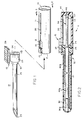
- Fig. 1 is a perspect view showing barrel and needle assembly of the injector;
- Fig. 2 is a side view of the injector, including a needle protector and the implant pellets;
- Fig. 3 shows the details of the two part obturator;
- Fig. 4A and 4B show the obturator in its assembled form;
- Fig. 5 shows the details of the slot in the injector barrel;
- Fig. 6A through 6D show the operation of the injector as it implants two pellets;
- Fig. 7 illustrates the desired fan shaped placement of the two implant pellets; and
- Fig. 8 shows an alternate embodiment of the present invention.
- Referring to Fig. 1, there is shown in perspective a view of the present invention. The invention includes a
barrel portion 11.Barrel 11 is open at thefront end 17 thereof. Thebarrel 11 is cylindrical in shape and is typically formed of plastic by means of injection molding or other suitable process. Therear end 14 ofbarrel 11 is closed. Aslot 20 extends from thefront portion 17 ofbarrel 11 is toward the rear and terminates just short of therear wall 14 of the barrel. - A needle or
cannula 21 is attached to ahub 26 to form aneedle assembly 12. The outside diameter of Hub 26 fits inside the hollow portion ofbarrel 11, so that the hub slides forward and backward within the barrel.Cannula 21 is typically formed of surgical steel and has abevel 23 at the distal end thereof. The bevel may be a "B" or "intravenous" cutting bevel of known type which allows the cannula to puncture the skin without a prior incision and without coring of flesh or body fluids. Other bevels may also be used. It should be clear that the described injector may also be used to implant medicaments through an existing incision made by other means. - Fig 2 shows a side view of the barrel and needle assembly at section line 2-2 in Fig. 1. In described embodiment,
hub 26 is made of molded plastic, although other materials may be used. A circular rear opening 25 inhub 26 extends the bore of thecannula 21 through the hub. The rear opening is slightly smaller in diameter than the inside diameter of the cannula. A plurality ofslots 29 extending from the opening 25 to the outside ofhub 26 are formed to allow the rear opening to expand slightly, and theseslots 29 cooperate with the obturator, as described in detail below, to enable multiple pellets to be implanted. - The
hub 26 is attached to aknob 10 which is designed to be engaged by the thumb of a person operating the injector while the barrel is held cupped in the fingers.Knob 10 is attached tohub 26 via aconnector piece 27. To assemble theneedle assembly 12 andbarrel 11,hub 26 is inserted in theopen end 17 of the barrel. Theconnector piece 27 between thethumb knob 10 and thehub 26 slides through thefront portion 15 ofslot 20. - The configuration of
slot 20 is shown in more detail in Fig. 5. In Fig. 5, theforward portion 15 ofslot 20 opens into anotch area 13.Slot portion 15 forms the bottom wall ofnotch 13.Notch area 13 is bounded by rear walls 16a and 16b on either side ofslot 20. Asecond portion 19 ofnotch 13 extends upwardly, as shown in Fig. 5, from the side of the notch. Thesecond porton 19 is bounded by afront wall 18. - The distance from
front wall 18 to rear wall 16b is such that theconnection 27 betweenhub 26 andthumb knob 10 is a tight friction fit. The main portion ofslot 20 extends rearwardly from theback walls 16 of the notch. During assembly, whenhub 26 is inserted into theopen end 17 ofbarrell 11, thethub knob connector 27 slides rearwardly intoslot 15 until it abuts back wall 16a. Theconnector 27 andthumb knob 10 are then moved in an upward direction, with reference to Fig. 5, until theconnector 27 abuts thetop wall 22 of the notch. The dimensions ofconnector 27 and notch 13 are such that the frictional forces will hold the connector and hencehub 26 andcannula 21 in position between rear wall 16a andfront wall 18 until the injector is to be used. - When the implanter is being used to implant pellets, the
thumb knob 10 is used to move theconnector 27 down fromlocation 19 until it can slide backwards inslot 20.Slot 20 is wide enough to allow the thumb piece andneedle assembly 12 to be moved forward and backward within the slot freely. - The width of
slot 15 through which theconnector piece 27 is inserted during assembly may be formed such that it is slightly narrower than the width of theconnection piece 27. When this is done, slot 15 must be open slightly in order to insert theneedle assembly 12. After theconnection piece 27 has completely passedentry slot 15, the slot will close slightly to assume its original dimension. Since this dimension is slighly narrower than the width ofconnector 27,connection piece 27 andneedle assembly 12 cannot be inadvertently slid out of the barrel throughentry slot 15 during operation. - Returning to Fig. 2,
barrel 11 andneedle assembly 12 are shown after they have been assembled together and before the instrument is used. In Fig. 2,hub 26 is located insidebarrel 11 with theconnector 27 andthumb knob 10 extending throughnotch 13. Anobturator 36, discussed in detail below, extends from therear wall 14 ofbarrel 11 into the proximal end ofhub 24.Obturator 36 fits into arecess 34 in therear wall 14 of the barrel and is held in place by friction or other suitable means. The proximal portion ofneedle 21 is inserted into the front ofhub 26 and fits in a recess therein. The opening 25 in the rear face ofhub 26 has an inside diameter substantially the same as the inside diameter of thecannula 21. Thus, a continuous bore from therear face 24 ofhub 26 through the distal end ofcannula 21 is formed. - Prior to being used, the implanter includes
medicinal implant pellets 42a and 42b contained within the bore defined bycannula 21 andhub 26.Pellets 42a and 42b are substantially the same length and have an outside diameter which allows them to slide freely within the bore. The proximal end of therearmost wall pellet 42b abuts the distal end ofobturator 36. The distal end of frontmost pellet 42a extends nearly to the distal end ofcannula 21. Prior to being used, acover 30 may be placed over theneedle assembly 12.Cover 30 is maintained in place via a frictional fit over afront stept 32 onhub 26.Cover 30 may include a plug 30a extending rearwardly from the distal end of the cover into the bore ofcannula 21 to maintainpellets 42 in place.Cover 30 may serve to maintain the sterility of the device prior to being used and also to guard the sharp end ofneedle 23 to prevent accidents. - In the described embodiment, each of the
implants 42 is 1.75 inches (0.04445 m) long. The length ofbarrel 11 frm itsfront end 17 to the rear wall insidesurface 37 is 2.60 inches (0.06604 m). The length ofslot 20 from therear walls 16 of thenotch area 19 to therear end 39 ofslot 20 should be slightly longer than the lenght of the implants and is 1.85 inches (0.04699 m) in the described embodiment. The inside diameter of the barrel is about 0.350 inches (8.89x10⁻³m) and the outside diameter ofhub 26 is 0.337 inches (8.56x10⁻³m). The length ofhub 26 along its axis is 0.625 inches (0.0159 m) andslots 29 extend forward for a distance 0.125 inches (3.175x10⁻³m) from the rear of the hub. Additional dimensions are discussed below. - Referring to Fig. 3, the details of
obturator 36 are shown.Obturator 36 is formed of two portions, including ahollow sleeve portion 38 and asolid core 40. Core portion includes amain shaft 44 and abase section 46. Thebase section 46 mounts in therecess 34 in the rear wall of the injector barrel, and the outside diameter of thebase 46 is chosen appropriately, but must be no larger than the outside diameter of the main section ofsleeve 38, as will become clear from the explanation below. Theobturator sleeve 38 is hollow and cylindrical shaped with the inside diameter of the sleeve very slightly larger than the outside diameter ofcore portion 44 of the obturator core so that the core may slide easily within the sleeve. - The end of the obturator core opposite the
base 46 is split, as shown in 48. Thesplit portion 48 extends a small distance back from the end of thecore shaft 44. The split is such that the two sections in the end of the obturator core separted by thesplit 48 may be compressed so that they will fit within the bore of theobturator sleeve 38. When removed from the bore, however, the split opens up so that the outside diameter ofend 50 of the obturator core is larger than the inside diameter ofsleeve 38. -
Sleeve 38 has a smooth inside bore of a substantially constant inside diameter. The outside diameter ofsleeve portion 38 is likewise substantially constant, except for asmall portion 52 at the rearmost end of the sleeve. The outside diameter ofportion 52 is slightly larger than the remainder ofsleeve 38 for reasons which will be discussed below. The amount of enlargement ofsection 52 is greatly exaggerated in the drawngs to illustrate the step more clearly. In the preferred embodiment, the outside diameter of the forward portion ofsleeve 38 is 0.100 inches (2.54x10⁻³m) while the outside diameter ofstep 52 is 0.102 to 0.104 inches (2.59x10⁻³ - 2.6x10⁻³m). Sleeve 33 is 1.85 inches (0.047 m) long, as is themain shaft secticn 44 of thecore 40.Base section 46 is slightly longer than the depth ofrecess 34, as shown in Figs. 2 and 6. - Figs 4A and 4B show the obturator when
core 40 is inserted withinsleeve 38. Fig. 4A represents the obturator with the core 40 fully insidesleeve 38, corresponding to the arrangement shown fully in Fig. 2. Fig. 4B shows the obturator core partially extending fromsleeve 38. In both Figs. 4A and 4B, it can be seen that the core split 48 has been compressed to fit inside the bore of the obturator sleeve. - Fig. 7 shows the preferred orientation for two implants. In Fig. 7, two
implants - Fig 6A through 6D show succeeding states in the operation of the injector and how it would be used to subcutaneously place implants beneath the skin of the patient in the fan pattern shown in Fig. 7. As shown in Fig. 2, Fig. 6A has two
implants 42a and 42b located within thecannula 21. Thehub 26 is located at the forward end ofslot 20. Theobturator core 40 is fully inserted within the bore ofobturator sleeve 38, and theobturator assembly 36 extends from therear wall 14 ofbarrel 11 into the back ofhub 26.Obturator 36 is in contact withrearmost pellet 42b which in turn is in contact with pellet 42a at the distal end ofcannula 21. - With the injector disposed as shown in Fig. 6A, the
beveled end 23 of the cannula is inserted beneath the skin of a patient. With the distal tip ofcannula 21 beneath the skin of a patient, the injector is manipulated to insertcannula 21 further beneath the skin until the forward implant 42a is in the desired location. At this point, the incision in the patient's skin through which the cannula is inserted should be located a small distance behind the distal end of therear inster 42b, as shown byincision line 54 in Fig. 6A. The engagement of the connectingpiece 27 withinnotch 19 of theslot 20 aids the operator in keeping therear hub 26 stationary with respect tobarrel 11 during the process of inserting the cannula subcutaneously. - After the operator is satisfied that the formost implant 42a is properly located,
hub 26 is disengaged fromnotch 19 and moved rearwardly inslot 20. This is shown in Fig. 6B in whicharrow 56 indicates the rearward motion ofhub 26. This rearward motion maybe quickly and easily accomplished by means of a thumb on the thumb-knob 10 while the barrel is held stationary by the operator's finges. Ashub 26 is moved rearwardly,cannula 21 also moves rearwardly and reacts from around the first implant 42a; leaving it in the desired location. -
Hub 26 is moved all the way rearwards inslot 20 untilconnection piece 27 abuts against therear wall 39 ofslot 20, to give the configuration shown in Fig. 6B. In 6B, the foremost implant 42a has been subcutaneously placed in the desired location and is substantially disengaged from the bore ofcannula 21, as shown in Fig. 6B. The distal end ofcannula 21 still extends for a small distance under the patient's skin through theincision 54. At this point, the injector operator would withdraw the entire injector a small amount to ensure that the end ofcannula 21 is fully disengaged from implant 42A. The end of the cannula remains under the skin and withinincision 54. - Next, the operator would move the
barrel 11 backward with respect tohub 26, as shown byarrow 60 in Fig. 6C. With the present invention, this may be easily done by holding thebarrel 11 in the fingers of one hand and moving it rearwardly while maintaining the hub and cannula in a fixed position with respect to the patient and with respect to theincision 54. The barrel is moved rearwardly until the connectingsection 27 again contacts the front wall ofnotch 19 so that the configuration of the injector is as shown in Fig. 6C with the end of the injector still slighly within theincision 54 and carrying thesecond implant 42b. - When
hub 26 is moved rearwardly to provide the configuration shown in Fig. 6B, therear face 24 of the hub passes over theenlarged portion 52 of theobturator sleeve 38. The inside diameter of the rear opening 25 inhub 26 is normally slightly smaller than the outside diameter ofenlarged portion 52. In the described embodiment, the diameter of opening 25 is 0.098 inches (2.49x10⁻³m). Theslots 29 inhub 26 allow it to open slightly and pass over theenlarged section 52 of the obturator sleeve. Ashub 26 is moved forward due to the frictional forces between theenlarged section 52 of the obturator sleeve and the inside hub rear opening 25. The dimensions of the implanter are such that when thehub 26 is moved to its forwardmost position, the rear of theobturator sleeve 38 is moved forward past the end of theobturator core 40. At this point, thesplit 48 in the end of the obturator core is no longer constrained by the inner walls of the obturator sleeve and expands, as shown in Fig. 6C. - With the tip of the cannula extending slightly through
incision 54 as shown in Fig. 6C, the injector is then pivoted while keeping the distal end of the cannula withinincision 54 so that thesecond implant 42b may be inserted next to the first implant in the previously describved fan shaped pattern. After being pivoted, the injector is moved forward through the incision to locate thesecond implant 42b beneath the skin of the patient. As the cannula is pushed beneath the skin to locate thesecond implant 42b, the incision moves fromlocation 54 tolocation 58 on the cannula so that thesecond implant 42b is located entirely beneath the skin and is surrounded by thecannula 21. - To finish the implantation process for the second implant, the hub is once more moved rearwardly with respect to the
barrel 11, as shown byarrow 62 in Fig. 6D. The frictional force between the expandedportion 52 of theobturator sleeve 38 and the inside ofhub 26 is overcome to allowhub 26 and attachedcannula 21 to slide backward past the expandedportion 52 which is hold in the forward position shown in Figs. 6C and 6D by thesplit end 50 of theobturator core 40. - As the
hub 26 is moved to its rearwardmost position withinbarrel 11, thecannula 21 moves rearwardly leaving theimplant 42b underneath the skin in the desired position. After thehub 26 has been moved all the way rearwardly, the disposition of the implanter and theimplants 42b are as shown in Fig. 6D. At this point, the instrument is withdrawn from theincision 58 and the implantation procedure is completed. - To summarize the operation of the injector and telescoping obturator, as the hub is moved from the rearward position shown in Fig. 6B to the forward position shown in Fig. 6C, the friction between the hub rear opening 25 and the
enlarged portion 52 of the obturator's sleeve causes the sleeve to be carried forward by the hub until it clears theobturator core 40. Once thesplit end 50 of theobturator core 40 is no longer constrained by the obturator'ssleeve 38, it opens and prevents theobturator 38 from moving rearwardly. As thehub 26 is moved rearwardly from the position shown in Fig. 6C to the position shown in Fig. 6D, the forward pressure on the obturator'ssleeve 38 by theobturator core 40 is sufficient to overcome the frictional forces betweeen thehub 26 and theenlarged portion 52 of the obturator's sleeve. Typically, the inside diameter of thecannula 21 is slightly larger than the outside diameter of theenlarged portion 52, although this is not shown in the drawings. In the preferred embodiment, the cannula has an inside diameter of 0.106 inches (2.69x10⁻³m) whilehub 26 has an inside diameter of 0.098 inches (2.49x10⁻³m). Thus, as thehub 26 is moved rearwardly, theenlarged portion 52 passes from within the hub rear opening 25 to the proximal end ofcannula 21. The frictional forces between theenlarged portion 52 andneedle assembly 12 are eliminated, allowing the hub to be moved rearwardly by the operator with ease. - The present invention may be manufactured inexpensively enough so that the injector and implants can be supplied as a pre-sterilized sealed package with the injector to be discarded after being used once. This is especially important if the invertion is used in remote or underdeveloped areas where sterile conditions may be hard to maintain.
- It should also be apparent that the obturator can comprise more than two sections where it is desired to implant more than two pellets. For example, a three-part telescoping obturator would be used to locate and expel from the cannula three implant pellets.
- Referring to Fig. 8, there is shown an alternate embodiment of the present invention. Figure 8 depicts the rearmost portion of
barrel 11. In Fig. 8, aspring 70 has been added to the apparatus. Thespring 70 extends from therear wall 14 of the obturator barrel to therear face 24 of the hub 26 (not shown in Fig. 8). The spring serves to provide a force to maintain the hub in a forward position withinslot 19 prior to being used, and further allows an operator to move thebarrel 11 rearward with respect to theneedle asembly 12, as shown in Fig. 6B, by relaxing slightly the grip of the operator's fingers upon the barrel so that thespring 70 will provide a force to move the barrel in a backward direction. To provide room forspring 70 when it is compressed between the hub andback wall 14 of thebarrel 11, the barrel may be extended rearwardly, as shown in Fig. 8. Anextension 74 has been added between theobturator base 46 and therear wall 14 of the barrel. Thebase 46 of the obturator fits withinrecess 34. Acylindrical space 76 between theextension 74 and the outside walls of theextended barrel 11 provides space forspring 70 as it is compressed when the hub and cannula are moved rearwardly.
Claims (10)
- A device for inserting and positioning a plurality of elongate implants (42a, 42b) beneath the skin comprising:
a long, hollow cannula (21) adapted for insertion beneath the skin;
a hub (26) to which the cannula (21) is attached so as to define a continuous bore;
a hollow body (11) within which said hub is slidably mounted so as to move between a proximal and distal position along an axis parallel to the continuous bore; and
an obturator (36) having distal and proximal ends; the device being characterised in that the obturator includes first (40) and second (38) sections which are connected so as to allow the first section (40) to move with respect to the second section (38) along an obturator axis;
the first section (40) of the obturator is mounted to the hollow body (11) in a manner such that the continuous bore is sufficiently long to contain said plurality of implants in an end-to-end relationship and slides over the obturator (36) as the hub (26) is moved between the distal and proximal positions;
the hub (26) and obturator (36,38,40) are further constructed and arranged so that the hub (26) may engage the obturator second section (38) when the hub is moved from the distal position to the proximal position, the engagement allowing the obturator second section (38) to be moved in a distal direction to an extended position with the hub (26) being subsequently moved from the proximal position to the distal position; and
the obturator (36,38,40) is further constructed and arranged such that after the hub (26) is moved from the proximal to the distal position, the obturator second section (38) is maintained in the extended position as the hub (26) is subsequently moved from the distal position toward the proximal position. - The apparatus of claim 1 wherein one of the obturator sections (40) slides within the other section (38) so that the obturator elongates by telescoping as the first section moves with respect to the second section.
- The apparatus of claim 1 wherein the obturator first section (40) is cylindrical and wherein the obturator second section (38) includes a cylindrical bore adapted to slide over the obturator first section.
- The apparatus of claim 3 wherein the obturator first section includes:
a cylindrical rod (44) having a slit (48) in the distal end thereof which forms at least two opposing legs;
means for applying a force to the opposing legs which tends to separate the legs;
and wherein the length of the obturator first and second sections (40,38) is such that the legs are constrained within the bore of the obturator second section until the hub (26) is moved from the proximal position to the distal position and are free, when the hub reaches the distal position, to extend outwardly beyond the cylindrical bore of the obturator second section thereby preventing the second section from moving in a proximal direction once the hub has been moved from the proximal to the distal position. - The apparatus of claim 1 wherein the body (11) includes a cylindrical barrel having a closed proximal end (14) to which the obturator first section (40) is mounted and an open distal end (17).
- The apparatus of claim 5 wherein the body (11) includes a slot (20) in the body having distal and proximal end walls (18) (39) and extending in a direction parallel to the continuous bore;
and wherein the hub includes a manually-actuable knob (10) extending through said slot and being constructed so that the knob abuts the distal and proximal ends of the slot respectively when the hub is in the distal and proximal positions. - The apparatus of claim 6 wherein the hub includes a plastic cylindrical portion having a metal cannula attached thereto, said manually-actuable knob being formed as an extension of the hub.
- The apparatus of claim 6 wherein the body includes an opening (15) extending from the open distal end of the housing to the distal wall of the slot to allow the hub knob to be inserted within said slot.
- The apparatus of claim 6 wherein the body includes a notch (13) at the distal end of said slot (20) and means associated with said notch for frictionally retaining the knob within the notch prior to use of said apparatus.
- The apparatus of claim 3 wherein the obturator second section (38) includes a cylinder with an enlarged outer diameter portion (52) at the proximal end thereof;
and wherein the hub has a metal cannula attached thereto, the hub including a cylindrical opening parallel and contiguous to the cannula bore and of a diameter substantially the same as said enlarged outer diameter portion and for providing a frictional interface between the hub opening walls and the enlarged outer diameter portion;
whereby the obturator second section is moved distally with respect to the obturator first portion as the hub is moved from the proximal position to the distal position.
Priority Applications (1)
| Application Number | Priority Date | Filing Date | Title |
|---|---|---|---|
| AT88903645T ATE88647T1 (en) | 1987-03-18 | 1988-03-18 | INJECTION DEVICE FOR IMPLANTING SEVERAL MEDICATION BEADS. |
Applications Claiming Priority (2)
| Application Number | Priority Date | Filing Date | Title |
|---|---|---|---|
| US07/027,565 US4846793A (en) | 1987-03-18 | 1987-03-18 | Injector for implanting multiple pellet medicaments |
| US27565 | 1987-03-18 |
Publications (3)
| Publication Number | Publication Date |
|---|---|
| EP0354918A1 EP0354918A1 (en) | 1990-02-21 |
| EP0354918A4 EP0354918A4 (en) | 1990-09-05 |
| EP0354918B1 true EP0354918B1 (en) | 1993-04-28 |
Family
ID=21838477
Family Applications (1)
| Application Number | Title | Priority Date | Filing Date |
|---|---|---|---|
| EP88903645A Expired - Lifetime EP0354918B1 (en) | 1987-03-18 | 1988-03-18 | Injector for implanting multiple pellet medicaments |
Country Status (7)
| Country | Link |
|---|---|
| US (1) | US4846793A (en) |
| EP (1) | EP0354918B1 (en) |
| AT (1) | ATE88647T1 (en) |
| CA (1) | CA1295201C (en) |
| DE (1) | DE3880676T2 (en) |
| FI (1) | FI894361A0 (en) |
| WO (1) | WO1988006905A1 (en) |
Cited By (1)
| Publication number | Priority date | Publication date | Assignee | Title |
|---|---|---|---|---|
| US6221003B1 (en) | 1999-07-26 | 2001-04-24 | Indigo Medical, Incorporated | Brachytherapy cartridge including absorbable and autoclaveable spacer |
Families Citing this family (84)
| Publication number | Priority date | Publication date | Assignee | Title |
|---|---|---|---|---|
| US4994028A (en) * | 1987-03-18 | 1991-02-19 | Endocon, Inc. | Injector for inplanting multiple pellet medicaments |
| SG49267A1 (en) * | 1989-08-14 | 1998-05-18 | Photogenesis Inc | Surgical instrument and cell isolation and transplantation |
| US6514238B1 (en) * | 1989-08-14 | 2003-02-04 | Photogenesis, Inc. | Method for preparation and transplantation of volute grafts and surgical instrument therefor |
| NL8903068A (en) * | 1989-12-14 | 1991-07-01 | Nedap Nv | CHARGING AND STORAGE DEVICE FOR IMPLANT PEN. |
| GB2240718A (en) * | 1990-02-09 | 1991-08-14 | Hundon Forge Ltd | Implanting device with needle cover |
| GB2241439A (en) * | 1990-02-28 | 1991-09-04 | Phillips Pty Ltd N J | Pellet implantor with lost motion means to prevent crushing |
| US5135493A (en) * | 1990-09-10 | 1992-08-04 | Pitman-Moore, Inc. | Strip cartridge adapter and strip cartridge for implant device |
| US5266325A (en) * | 1990-09-28 | 1993-11-30 | Hydro Med Science Division Of National Patent Development Corp. | Preparation of homogeneous hydrogel copolymers |
| AU651654B2 (en) * | 1992-01-14 | 1994-07-28 | Endo Pharmaceuticals Solutions Inc. | Manufacture of water-swellable hydrophilic articles and drug delivery devices |
| US5281197A (en) * | 1992-07-27 | 1994-01-25 | Symbiosis Corporation | Endoscopic hemostatic agent delivery system |
| US5279555A (en) * | 1992-08-24 | 1994-01-18 | Merck & Co., Inc. | Device for injecting implants |
| US5304119A (en) * | 1993-06-24 | 1994-04-19 | Monsanto Company | Instrument for injecting implants through animal hide |
| FI934513A (en) * | 1993-10-13 | 1995-04-14 | Leiras Oy | Anordning Foer injection with implant |
| DE9403161U1 (en) * | 1994-02-25 | 1994-04-21 | Süddeutsche Feinmechanik GmbH, 63607 Wächtersbach | Cannula |
| US5595752A (en) * | 1994-07-01 | 1997-01-21 | Monsanto Company | Increasing dressing percentage and carcass weight in finishing beef cattle |
| US5672357A (en) * | 1994-07-01 | 1997-09-30 | Monsanto Company | Method and device for implantation of large diameter objects in bovines |
| EP0783342B1 (en) * | 1994-09-27 | 1998-11-04 | Delab | Safety injection device |
| WO1997022379A2 (en) * | 1995-12-18 | 1997-06-26 | Kerisma Medical Products, L.L.C. | Fiberoptic-guided interstitial seed manual applicator and seed cartridge |
| HU220126B (en) | 1996-09-27 | 2001-11-28 | American Home Products Corporation | Medical device for inserting solid materials either under a tissue or under the skin |
| WO1998013092A1 (en) | 1996-09-27 | 1998-04-02 | American Home Products Corporation | Tissue penetration guide |
| US5984890A (en) * | 1996-09-27 | 1999-11-16 | American Home Products Corporation | Medical device for the placement of solid materials |
| US7445612B2 (en) | 1996-12-31 | 2008-11-04 | Société de Conseils de Recherches et d'Applications Scientifiques, S.A.S. | Safety injection device for a liquid or semi-solid composition |
| US5776107A (en) | 1996-12-31 | 1998-07-07 | Delab | Injection device |
| KR100246044B1 (en) * | 1998-02-20 | 2000-03-15 | 성재갑 | Administration device |
| US6245052B1 (en) * | 1998-07-08 | 2001-06-12 | Innerdyne, Inc. | Methods, systems, and kits for implanting articles |
| US6488649B1 (en) | 1998-11-24 | 2002-12-03 | Edward M. Lichten | Implant device |
| PL351949A1 (en) | 1999-04-26 | 2003-07-14 | Gmp Vision Solutions | Stent and method of treating glaucoma |
| US7153312B1 (en) | 1999-12-02 | 2006-12-26 | Smith & Nephew Inc. | Closure device and method for tissue repair |
| US7887551B2 (en) | 1999-12-02 | 2011-02-15 | Smith & Nephew, Inc. | Soft tissue attachment and repair |
| US6450938B1 (en) * | 2000-03-21 | 2002-09-17 | Promex, Llc | Brachytherapy device |
| US6638239B1 (en) | 2000-04-14 | 2003-10-28 | Glaukos Corporation | Apparatus and method for treating glaucoma |
| US7867186B2 (en) * | 2002-04-08 | 2011-01-11 | Glaukos Corporation | Devices and methods for treatment of ocular disorders |
| US7708711B2 (en) | 2000-04-14 | 2010-05-04 | Glaukos Corporation | Ocular implant with therapeutic agents and methods thereof |
| ES2304438T3 (en) | 2001-04-07 | 2008-10-16 | Glaukos Corporation | GLAUCOMA STENT FOR THE TREATMENT OF GLAUCOMA. |
| US7431710B2 (en) | 2002-04-08 | 2008-10-07 | Glaukos Corporation | Ocular implants with anchors and methods thereof |
| US7678065B2 (en) | 2001-05-02 | 2010-03-16 | Glaukos Corporation | Implant with intraocular pressure sensor for glaucoma treatment |
| AU2002305400A1 (en) | 2001-05-03 | 2002-11-18 | Glaukos Corporation | Medical device and methods of use for glaucoma treatment |
| US6648849B2 (en) | 2001-06-27 | 2003-11-18 | Ethicon, Inc. | Medicinal implant and device and method for loading and delivering implants containing drugs and cells |
| US8877233B2 (en) * | 2001-06-29 | 2014-11-04 | Cook Biotech Incorporated | Porous sponge matrix medical devices and methods |
| CA2453822C (en) * | 2001-08-03 | 2011-02-22 | Tyco Healthcare Group Lp | Tissue marking apparatus and method |
| US7331984B2 (en) | 2001-08-28 | 2008-02-19 | Glaukos Corporation | Glaucoma stent for treating glaucoma and methods of use |
| EP1323450B1 (en) * | 2001-12-18 | 2004-09-22 | Rexam Pharma GmbH | Syringe device |
| US7186232B1 (en) | 2002-03-07 | 2007-03-06 | Glaukoa Corporation | Fluid infusion methods for glaucoma treatment |
| US7951155B2 (en) | 2002-03-15 | 2011-05-31 | Glaukos Corporation | Combined treatment for cataract and glaucoma treatment |
| US9301875B2 (en) | 2002-04-08 | 2016-04-05 | Glaukos Corporation | Ocular disorder treatment implants with multiple opening |
| US20050256361A1 (en) * | 2002-07-03 | 2005-11-17 | Christian Mathieu | Implant inserting device |
| US9314235B2 (en) * | 2003-02-05 | 2016-04-19 | Smith & Nephew, Inc. | Tissue anchor and insertion tool |
| US7214206B2 (en) * | 2003-04-03 | 2007-05-08 | Valera Pharmaceuticals, Inc. | Implanting device and method of using same |
| US20050159762A1 (en) * | 2003-12-30 | 2005-07-21 | Juha-Pekka Nuutinen | Suture arrow device and installation device |
| US20050250788A1 (en) * | 2004-01-30 | 2005-11-10 | Hosheng Tu | Aqueous outflow enhancement with vasodilated aqueous cavity |
| US7137995B2 (en) * | 2004-03-01 | 2006-11-21 | Jsm Licensing, Llc. | Breast implant injector and method of use |
| EP1773293B1 (en) | 2004-06-17 | 2015-04-15 | Endo Pharmaceuticals Solutions Inc. | Compositions and methods for treating central precocious puberty |
| WO2006099288A2 (en) * | 2005-03-11 | 2006-09-21 | Indevus Pharmaceuticals, Inc. | Controlled release formulations of octreotide |
| US20060293709A1 (en) | 2005-06-24 | 2006-12-28 | Bojarski Raymond A | Tissue repair device |
| US20070293807A1 (en) * | 2006-05-01 | 2007-12-20 | Lynch Mary G | Dual drainage pathway shunt device and method for treating glaucoma |
| WO2008061043A2 (en) | 2006-11-10 | 2008-05-22 | Glaukos Corporation | Uveoscleral shunt and methods for implanting same |
| AU2008245710B2 (en) * | 2007-04-27 | 2013-10-17 | Endo Pharmaceuticals Solutions Inc. | Implant device release agents and methods of using same |
| CN102131717A (en) * | 2008-06-23 | 2011-07-20 | D·拉普科 | Apparatus for picking up, holding and dispensing objects |
| CA2729139C (en) * | 2008-06-25 | 2016-07-26 | Endo Pharmaceuticals Solutions Inc. | Octreotide implant having a release agent |
| EP2303226B1 (en) | 2008-06-25 | 2016-03-23 | Endo Pharmaceuticals Solutions Inc. | Sustained delivery of exenatide and other polypeptides |
| WO2010093945A2 (en) | 2009-02-13 | 2010-08-19 | Glaukos Corporation | Uveoscleral drug delivery implant and methods for implanting the same |
| CN102448536B (en) * | 2009-03-27 | 2014-06-04 | 诺沃—诺迪斯克有限公司 | Solid dose delivery device |
| US10206813B2 (en) | 2009-05-18 | 2019-02-19 | Dose Medical Corporation | Implants with controlled drug delivery features and methods of using same |
| US20110306820A1 (en) * | 2010-06-14 | 2011-12-15 | Coloplast A/S | Method of treating incontinence |
| EP2654715B1 (en) | 2010-11-24 | 2017-01-25 | Dose Medical Corporation | Drug eluting ocular implant |
| GB201101087D0 (en) * | 2011-01-21 | 2011-03-09 | Glide Pharmaceutical Technologies Ltd | Drug delivery technology |
| US20140005595A1 (en) * | 2011-03-17 | 2014-01-02 | Cell Precision, LLC | Delivery devices and methods for delivering therapeutic agents |
| US10245178B1 (en) | 2011-06-07 | 2019-04-02 | Glaukos Corporation | Anterior chamber drug-eluting ocular implant |
| WO2013040079A1 (en) | 2011-09-13 | 2013-03-21 | Dose Medical Corporation | Intraocular physiological sensor |
| JP6465490B2 (en) | 2012-03-26 | 2019-02-06 | グローコス コーポレーション | Implant delivery device |
| AU2013204739B2 (en) * | 2012-04-21 | 2016-10-20 | Paul Jason Barrot | Apparatus for plugging holes |
| US9687372B2 (en) | 2012-10-17 | 2017-06-27 | C.R. Bard, Inc. | Hand unit to release a self-expanding implant |
| US9730638B2 (en) | 2013-03-13 | 2017-08-15 | Glaukos Corporation | Intraocular physiological sensor |
| US9592151B2 (en) | 2013-03-15 | 2017-03-14 | Glaukos Corporation | Systems and methods for delivering an ocular implant to the suprachoroidal space within an eye |
| EP3148491B1 (en) | 2014-05-29 | 2020-07-01 | Glaukos Corporation | Implants with controlled drug delivery features and manufacturing method for said implants |
| WO2017040853A1 (en) | 2015-09-02 | 2017-03-09 | Glaukos Corporation | Drug delivery implants with bi-directional delivery capacity |
| US11564833B2 (en) | 2015-09-25 | 2023-01-31 | Glaukos Corporation | Punctal implants with controlled drug delivery features and methods of using same |
| CN115120405A (en) | 2016-04-20 | 2022-09-30 | 多斯医学公司 | Delivery device for bioabsorbable ocular drugs |
| DE202017105048U1 (en) | 2017-08-23 | 2017-09-05 | H & B Electronic Gmbh & Co. Kg | Device for implantation |
| US11116625B2 (en) | 2017-09-28 | 2021-09-14 | Glaukos Corporation | Apparatus and method for controlling placement of intraocular implants |
| US11376040B2 (en) | 2017-10-06 | 2022-07-05 | Glaukos Corporation | Systems and methods for delivering multiple ocular implants |
| USD846738S1 (en) | 2017-10-27 | 2019-04-23 | Glaukos Corporation | Implant delivery apparatus |
| DE102018208085A1 (en) * | 2018-05-23 | 2019-11-28 | Biotronik Se & Co. Kg | Implantation tool for subcutaneous implantation of a medical implant |
| EP4061239A1 (en) * | 2019-11-21 | 2022-09-28 | Bardy Diagnostics, Inc. | Insertable physiological monitor injector tool |
Family Cites Families (15)
| Publication number | Priority date | Publication date | Assignee | Title |
|---|---|---|---|---|
| US939693A (en) * | 1908-05-05 | 1909-11-09 | John Holtzmann | Instrument for handling semiplastic substances. |
| US2269963A (en) * | 1940-06-01 | 1942-01-13 | Wappler Frederick Charles | Implanting device |
| US2513014A (en) * | 1946-11-18 | 1950-06-27 | Abbott Lab | Apparatus for implanting medicinal pellets subcutaneously |
| US2718299A (en) * | 1950-06-01 | 1955-09-20 | Verne L Atwater | Medicinal dispenser |
| US2885116A (en) * | 1953-12-17 | 1959-05-05 | Harold R Tregilgas | Pocket tablet dispenser and unit tablet container therefor |
| US2761446A (en) * | 1955-03-30 | 1956-09-04 | Chemical Specialties Co Inc | Implanter and cartridge |
| US3992796A (en) * | 1974-11-29 | 1976-11-23 | Roger Dorgnon | System for introducing and placing caseless pellets in a firing apparatus |
| GB1525841A (en) * | 1976-05-18 | 1978-09-20 | Hundon Forge Ltd | Drug implanters |
| US4086914A (en) * | 1977-02-11 | 1978-05-02 | Edwin Bailey Moore | Implant injector |
| US4174048A (en) * | 1977-10-04 | 1979-11-13 | Volpe John J Jr | Tablet retaining and dispensing device |
| US4223674A (en) * | 1978-06-29 | 1980-09-23 | Arthur J. McIntosh | Implant gun |
| US4666103A (en) * | 1980-02-04 | 1987-05-19 | Allen John B | Carrier tracking system |
| US4451253A (en) * | 1980-12-18 | 1984-05-29 | Harman Sherman M | Means and method for administering medicinals |
| US4451254A (en) * | 1982-03-15 | 1984-05-29 | Eli Lilly And Company | Implant system |
| US4753636A (en) * | 1983-08-02 | 1988-06-28 | Endocon, Inc. | Subcutaneous implant kit |
-
1987
- 1987-03-18 US US07/027,565 patent/US4846793A/en not_active Expired - Fee Related
-
1988
- 1988-03-18 WO PCT/US1988/000984 patent/WO1988006905A1/en active IP Right Grant
- 1988-03-18 CA CA000561876A patent/CA1295201C/en not_active Expired - Fee Related
- 1988-03-18 DE DE8888903645T patent/DE3880676T2/en not_active Expired - Fee Related
- 1988-03-18 AT AT88903645T patent/ATE88647T1/en not_active IP Right Cessation
- 1988-03-18 EP EP88903645A patent/EP0354918B1/en not_active Expired - Lifetime
-
1989
- 1989-09-15 FI FI894361A patent/FI894361A0/en not_active Application Discontinuation
Cited By (1)
| Publication number | Priority date | Publication date | Assignee | Title |
|---|---|---|---|---|
| US6221003B1 (en) | 1999-07-26 | 2001-04-24 | Indigo Medical, Incorporated | Brachytherapy cartridge including absorbable and autoclaveable spacer |
Also Published As
| Publication number | Publication date |
|---|---|
| WO1988006905A1 (en) | 1988-09-22 |
| EP0354918A1 (en) | 1990-02-21 |
| CA1295201C (en) | 1992-02-04 |
| DE3880676D1 (en) | 1993-06-03 |
| FI894361A0 (en) | 1989-09-15 |
| DE3880676T2 (en) | 1993-08-19 |
| ATE88647T1 (en) | 1993-05-15 |
| EP0354918A4 (en) | 1990-09-05 |
| US4846793A (en) | 1989-07-11 |
Similar Documents
| Publication | Publication Date | Title |
|---|---|---|
| EP0354918B1 (en) | Injector for implanting multiple pellet medicaments | |
| US4994028A (en) | Injector for inplanting multiple pellet medicaments | |
| US6966899B2 (en) | Hand-piece for injection device with a retractable and rotating needle | |
| US7850639B2 (en) | Implantation device for subcutaneous implantation of an object under the skin | |
| US5562613A (en) | Subcutaneous drug delivery device | |
| RU2192285C2 (en) | Medical apparatus for inserting solid materials | |
| JPH10503094A (en) | Percutaneous port catheter and method of using the same | |
| JP2012020189A (en) | Device for injecting pharmaceutical active factor | |
| RU2277945C2 (en) | Catheter and method for its using | |
| AU738006B2 (en) | Preloaded implantation device | |
| MXPA99011692A (en) | Preloaded implantation device |
Legal Events
| Date | Code | Title | Description |
|---|---|---|---|
| PUAI | Public reference made under article 153(3) epc to a published international application that has entered the european phase |
Free format text: ORIGINAL CODE: 0009012 |
|
| 17P | Request for examination filed |
Effective date: 19890918 |
|
| AK | Designated contracting states |
Kind code of ref document: A1 Designated state(s): AT BE CH DE FR GB IT LI LU NL SE |
|
| A4 | Supplementary search report drawn up and despatched |
Effective date: 19900716 |
|
| AK | Designated contracting states |
Kind code of ref document: A4 Designated state(s): AT BE CH DE FR GB IT LI LU NL SE |
|
| 17Q | First examination report despatched |
Effective date: 19911129 |
|
| GRAA | (expected) grant |
Free format text: ORIGINAL CODE: 0009210 |
|
| ITF | It: translation for a ep patent filed | ||
| AK | Designated contracting states |
Kind code of ref document: B1 Designated state(s): AT BE CH DE FR GB IT LI LU NL SE |
|
| REF | Corresponds to: |
Ref document number: 88647 Country of ref document: AT Date of ref document: 19930515 Kind code of ref document: T |
|
| REF | Corresponds to: |
Ref document number: 3880676 Country of ref document: DE Date of ref document: 19930603 |
|
| ET | Fr: translation filed | ||
| PGFP | Annual fee paid to national office [announced via postgrant information from national office to epo] |
Ref country code: FR Payment date: 19940209 Year of fee payment: 7 |
|
| PGFP | Annual fee paid to national office [announced via postgrant information from national office to epo] |
Ref country code: CH Payment date: 19940211 Year of fee payment: 7 |
|
| PGFP | Annual fee paid to national office [announced via postgrant information from national office to epo] |
Ref country code: AT Payment date: 19940214 Year of fee payment: 7 |
|
| PGFP | Annual fee paid to national office [announced via postgrant information from national office to epo] |
Ref country code: SE Payment date: 19940216 Year of fee payment: 7 Ref country code: GB Payment date: 19940216 Year of fee payment: 7 |
|
| PGFP | Annual fee paid to national office [announced via postgrant information from national office to epo] |
Ref country code: DE Payment date: 19940217 Year of fee payment: 7 |
|
| PGFP | Annual fee paid to national office [announced via postgrant information from national office to epo] |
Ref country code: BE Payment date: 19940224 Year of fee payment: 7 |
|
| PLBE | No opposition filed within time limit |
Free format text: ORIGINAL CODE: 0009261 |
|
| STAA | Information on the status of an ep patent application or granted ep patent |
Free format text: STATUS: NO OPPOSITION FILED WITHIN TIME LIMIT |
|
| PGFP | Annual fee paid to national office [announced via postgrant information from national office to epo] |
Ref country code: NL Payment date: 19940331 Year of fee payment: 7 Ref country code: LU Payment date: 19940331 Year of fee payment: 7 |
|
| 26N | No opposition filed | ||
| EPTA | Lu: last paid annual fee | ||
| EAL | Se: european patent in force in sweden |
Ref document number: 88903645.5 |
|
| PG25 | Lapsed in a contracting state [announced via postgrant information from national office to epo] |
Ref country code: LU Free format text: LAPSE BECAUSE OF NON-PAYMENT OF DUE FEES Effective date: 19950318 Ref country code: GB Effective date: 19950318 Ref country code: AT Effective date: 19950318 |
|
| PG25 | Lapsed in a contracting state [announced via postgrant information from national office to epo] |
Ref country code: SE Effective date: 19950319 |
|
| PG25 | Lapsed in a contracting state [announced via postgrant information from national office to epo] |
Ref country code: LI Effective date: 19950331 Ref country code: CH Effective date: 19950331 Ref country code: BE Effective date: 19950331 |
|
| BERE | Be: lapsed |
Owner name: ENDOCON INC. Effective date: 19950331 |
|
| PG25 | Lapsed in a contracting state [announced via postgrant information from national office to epo] |
Ref country code: NL Effective date: 19951001 |
|
| GBPC | Gb: european patent ceased through non-payment of renewal fee |
Effective date: 19950318 |
|
| PG25 | Lapsed in a contracting state [announced via postgrant information from national office to epo] |
Ref country code: FR Free format text: LAPSE BECAUSE OF NON-PAYMENT OF DUE FEES Effective date: 19951130 |
|
| REG | Reference to a national code |
Ref country code: CH Ref legal event code: PL |
|
| NLV4 | Nl: lapsed or anulled due to non-payment of the annual fee |
Effective date: 19951001 |
|
| PG25 | Lapsed in a contracting state [announced via postgrant information from national office to epo] |
Ref country code: DE Effective date: 19951201 |
|
| EUG | Se: european patent has lapsed |
Ref document number: 88903645.5 |
|
| REG | Reference to a national code |
Ref country code: FR Ref legal event code: ST |
|
| PG25 | Lapsed in a contracting state [announced via postgrant information from national office to epo] |
Ref country code: IT Free format text: LAPSE BECAUSE OF NON-PAYMENT OF DUE FEES;WARNING: LAPSES OF ITALIAN PATENTS WITH EFFECTIVE DATE BEFORE 2007 MAY HAVE OCCURRED AT ANY TIME BEFORE 2007. THE CORRECT EFFECTIVE DATE MAY BE DIFFERENT FROM THE ONE RECORDED. Effective date: 20050318 |