EP0354861A1 - Apparatus, use and process for producing a regulator of a very low gas flow with a sonic flow velocity for measuring gas adsorption and desorption - Google Patents
Apparatus, use and process for producing a regulator of a very low gas flow with a sonic flow velocity for measuring gas adsorption and desorption Download PDFInfo
- Publication number
- EP0354861A1 EP0354861A1 EP89430022A EP89430022A EP0354861A1 EP 0354861 A1 EP0354861 A1 EP 0354861A1 EP 89430022 A EP89430022 A EP 89430022A EP 89430022 A EP89430022 A EP 89430022A EP 0354861 A1 EP0354861 A1 EP 0354861A1
- Authority
- EP
- European Patent Office
- Prior art keywords
- pressure
- tube
- gas
- flow rate
- regulator
- Prior art date
- Legal status (The legal status is an assumption and is not a legal conclusion. Google has not performed a legal analysis and makes no representation as to the accuracy of the status listed.)
- Granted
Links
- 238000001179 sorption measurement Methods 0.000 title claims abstract description 57
- 238000000034 method Methods 0.000 title claims abstract description 39
- 238000003795 desorption Methods 0.000 title claims abstract description 23
- 230000008569 process Effects 0.000 title description 4
- 238000005259 measurement Methods 0.000 claims abstract description 29
- 238000004519 manufacturing process Methods 0.000 claims abstract description 22
- 229910052751 metal Inorganic materials 0.000 claims abstract description 9
- 239000002184 metal Substances 0.000 claims abstract description 9
- 230000001105 regulatory effect Effects 0.000 claims abstract description 5
- 239000007789 gas Substances 0.000 claims description 80
- IJGRMHOSHXDMSA-UHFFFAOYSA-N Atomic nitrogen Chemical compound N#N IJGRMHOSHXDMSA-UHFFFAOYSA-N 0.000 claims description 22
- 238000011144 upstream manufacturing Methods 0.000 claims description 20
- 239000003463 adsorbent Substances 0.000 claims description 15
- 229910052757 nitrogen Inorganic materials 0.000 claims description 11
- 239000000463 material Substances 0.000 claims description 7
- 239000002356 single layer Substances 0.000 claims description 7
- RYGMFSIKBFXOCR-UHFFFAOYSA-N Copper Chemical compound [Cu] RYGMFSIKBFXOCR-UHFFFAOYSA-N 0.000 claims description 6
- 229910052802 copper Inorganic materials 0.000 claims description 6
- 239000010949 copper Substances 0.000 claims description 6
- 238000006073 displacement reaction Methods 0.000 claims description 5
- 230000000717 retained effect Effects 0.000 claims description 4
- 230000015572 biosynthetic process Effects 0.000 claims description 2
- 230000006870 function Effects 0.000 description 11
- 238000002474 experimental method Methods 0.000 description 7
- 239000011148 porous material Substances 0.000 description 6
- 239000000523 sample Substances 0.000 description 6
- 238000004438 BET method Methods 0.000 description 4
- VYPSYNLAJGMNEJ-UHFFFAOYSA-N Silicium dioxide Chemical compound O=[Si]=O VYPSYNLAJGMNEJ-UHFFFAOYSA-N 0.000 description 4
- 238000012360 testing method Methods 0.000 description 4
- 230000008901 benefit Effects 0.000 description 3
- 238000000892 gravimetry Methods 0.000 description 3
- 229920006395 saturated elastomer Polymers 0.000 description 3
- XKRFYHLGVUSROY-UHFFFAOYSA-N Argon Chemical compound [Ar] XKRFYHLGVUSROY-UHFFFAOYSA-N 0.000 description 2
- OKTJSMMVPCPJKN-UHFFFAOYSA-N Carbon Chemical compound [C] OKTJSMMVPCPJKN-UHFFFAOYSA-N 0.000 description 2
- 229910052786 argon Inorganic materials 0.000 description 2
- 238000009833 condensation Methods 0.000 description 2
- 230000005494 condensation Effects 0.000 description 2
- 238000001514 detection method Methods 0.000 description 2
- 238000010586 diagram Methods 0.000 description 2
- 239000000499 gel Substances 0.000 description 2
- 230000014509 gene expression Effects 0.000 description 2
- PCHJSUWPFVWCPO-UHFFFAOYSA-N gold Chemical compound [Au] PCHJSUWPFVWCPO-UHFFFAOYSA-N 0.000 description 2
- 229910052737 gold Inorganic materials 0.000 description 2
- 239000010931 gold Substances 0.000 description 2
- 239000010410 layer Substances 0.000 description 2
- 239000007788 liquid Substances 0.000 description 2
- BASFCYQUMIYNBI-UHFFFAOYSA-N platinum Chemical compound [Pt] BASFCYQUMIYNBI-UHFFFAOYSA-N 0.000 description 2
- 239000000843 powder Substances 0.000 description 2
- 239000000377 silicon dioxide Substances 0.000 description 2
- 229910052709 silver Inorganic materials 0.000 description 2
- 239000004332 silver Substances 0.000 description 2
- 239000007787 solid Substances 0.000 description 2
- 239000000243 solution Substances 0.000 description 2
- 238000002336 sorption--desorption measurement Methods 0.000 description 2
- 238000000207 volumetry Methods 0.000 description 2
- XLYOFNOQVPJJNP-UHFFFAOYSA-N water Chemical compound O XLYOFNOQVPJJNP-UHFFFAOYSA-N 0.000 description 2
- BQCADISMDOOEFD-UHFFFAOYSA-N Silver Chemical compound [Ag] BQCADISMDOOEFD-UHFFFAOYSA-N 0.000 description 1
- 229910000831 Steel Inorganic materials 0.000 description 1
- NINIDFKCEFEMDL-UHFFFAOYSA-N Sulfur Chemical compound [S] NINIDFKCEFEMDL-UHFFFAOYSA-N 0.000 description 1
- 230000009471 action Effects 0.000 description 1
- 238000002159 adsorption--desorption isotherm Methods 0.000 description 1
- 238000004458 analytical method Methods 0.000 description 1
- 239000011230 binding agent Substances 0.000 description 1
- 230000033228 biological regulation Effects 0.000 description 1
- 238000009835 boiling Methods 0.000 description 1
- 238000004364 calculation method Methods 0.000 description 1
- 239000012159 carrier gas Substances 0.000 description 1
- 239000003054 catalyst Substances 0.000 description 1
- 238000012512 characterization method Methods 0.000 description 1
- 238000006243 chemical reaction Methods 0.000 description 1
- 238000011437 continuous method Methods 0.000 description 1
- 238000001816 cooling Methods 0.000 description 1
- 238000012937 correction Methods 0.000 description 1
- 230000001419 dependent effect Effects 0.000 description 1
- 238000013461 design Methods 0.000 description 1
- 238000005553 drilling Methods 0.000 description 1
- 229920001971 elastomer Polymers 0.000 description 1
- 238000005516 engineering process Methods 0.000 description 1
- 238000011156 evaluation Methods 0.000 description 1
- 239000000945 filler Substances 0.000 description 1
- 238000007429 general method Methods 0.000 description 1
- 239000011521 glass Substances 0.000 description 1
- 229930195733 hydrocarbon Natural products 0.000 description 1
- 150000002430 hydrocarbons Chemical class 0.000 description 1
- 230000006872 improvement Effects 0.000 description 1
- 238000002347 injection Methods 0.000 description 1
- 239000007924 injection Substances 0.000 description 1
- 238000009434 installation Methods 0.000 description 1
- 230000002427 irreversible effect Effects 0.000 description 1
- 238000002955 isolation Methods 0.000 description 1
- 230000014759 maintenance of location Effects 0.000 description 1
- 230000005499 meniscus Effects 0.000 description 1
- 238000012986 modification Methods 0.000 description 1
- 230000004048 modification Effects 0.000 description 1
- 239000002808 molecular sieve Substances 0.000 description 1
- 229920000620 organic polymer Polymers 0.000 description 1
- 239000000049 pigment Substances 0.000 description 1
- 239000004033 plastic Substances 0.000 description 1
- 229920003023 plastic Polymers 0.000 description 1
- 229910052697 platinum Inorganic materials 0.000 description 1
- 238000005086 pumping Methods 0.000 description 1
- 238000011002 quantification Methods 0.000 description 1
- 238000013214 routine measurement Methods 0.000 description 1
- 239000010979 ruby Substances 0.000 description 1
- 229910001750 ruby Inorganic materials 0.000 description 1
- URGAHOPLAPQHLN-UHFFFAOYSA-N sodium aluminosilicate Chemical compound [Na+].[Al+3].[O-][Si]([O-])=O.[O-][Si]([O-])=O URGAHOPLAPQHLN-UHFFFAOYSA-N 0.000 description 1
- 229910001220 stainless steel Inorganic materials 0.000 description 1
- 239000010935 stainless steel Substances 0.000 description 1
- 239000010959 steel Substances 0.000 description 1
- 239000000126 substance Substances 0.000 description 1
- 229910052717 sulfur Inorganic materials 0.000 description 1
- 239000011593 sulfur Substances 0.000 description 1
- 230000007704 transition Effects 0.000 description 1
Images
Classifications
-
- G—PHYSICS
- G05—CONTROLLING; REGULATING
- G05D—SYSTEMS FOR CONTROLLING OR REGULATING NON-ELECTRIC VARIABLES
- G05D7/00—Control of flow
- G05D7/01—Control of flow without auxiliary power
- G05D7/0186—Control of flow without auxiliary power without moving parts
-
- G—PHYSICS
- G01—MEASURING; TESTING
- G01N—INVESTIGATING OR ANALYSING MATERIALS BY DETERMINING THEIR CHEMICAL OR PHYSICAL PROPERTIES
- G01N15/00—Investigating characteristics of particles; Investigating permeability, pore-volume or surface-area of porous materials
- G01N15/08—Investigating permeability, pore-volume, or surface area of porous materials
- G01N15/0806—Details, e.g. sample holders, mounting samples for testing
-
- G—PHYSICS
- G01—MEASURING; TESTING
- G01N—INVESTIGATING OR ANALYSING MATERIALS BY DETERMINING THEIR CHEMICAL OR PHYSICAL PROPERTIES
- G01N15/00—Investigating characteristics of particles; Investigating permeability, pore-volume or surface-area of porous materials
- G01N15/08—Investigating permeability, pore-volume, or surface area of porous materials
- G01N15/088—Investigating volume, surface area, size or distribution of pores; Porosimetry
- G01N15/0893—Investigating volume, surface area, size or distribution of pores; Porosimetry by measuring weight or volume of sorbed fluid, e.g. B.E.T. method
Definitions
- the present invention relates to devices, applications and methods for manufacturing a regulator capable of ensuring very low sonic flow rate for gas adsorption and desorption measurements.
- the technical sector of the invention is that of the manufacture of gas volume measurement equipment.
- An application of the invention is the determination of the specific area of an adsorbent by the continuous introduction of adsorbable gas with very high precision.
- gas adsorption retention of gases at the surface
- porous or divided solids such as catalysts, adsorbents for purifying or separating gases or liquids, pigments, hydraulic binders, fillers for rubber or plastics, phytosanitary powders, etc.
- the gases used for these characterizations are sometimes chemisorbed (in particular H2, CO, NH3, O2 as well as various hydrocarbons) sometimes physisorbed (in particular N2, Ar, Kr, CO2, H2O).
- the quantification and exploitation of the adsorption phenomenon always involves the determination of more or less complete adsorption isotherms, that is to say the curves giving, at a given temperature, the quantity of gas adsorbed at equilibrium as a function of the pressure of this gas above the adsorbent; when the gas can give rise to three-dimensional condensation at the temperature of the experiment, the equilibrium pressure is usually expressed in relation to the saturated vapor pressure at this temperature and we speak of relative equilibrium pressure.
- the quantity of adsorbed gas is usually determined either by gas volumetry, or by gravimetry, or again by measuring variations in the concentration of the adsorbable gas in a carrier gas, using a catharometric detector. These three methods are usually used for a discontinuous determination of a limited number of points of the adsorption isotherm. It has long been sought to avoid the limitations of this discontinuous procedure (limitations in resolution and limitations in experimental convenience) by the use of a procedure of slow and continuous introduction of the adsorbable gas.
- the improvement in the measurements obtained encountered, up to the present invention the need to operate at adsorption flow rates of between 0.03 and 3 mm 3 (at normal temperature and pressure conditions: TPN) per second in order to to ensure satisfactory quasi-equilibrium conditions: it is indeed difficult to on the one hand to obtain such a flow, on the other hand to keep it stable for the duration of an experiment (between 15 min and 15 h) taking into account the variations of the atmospheric pressure and the increase in the pressure of almost balance during adsorption, and finally to be able to measure it.
- TPN normal temperature and pressure conditions
- adjustable high-precision leakage valves such as those used for calibrating mass spectometers, sintered metal powder filters, drawn capillary tubes (of glass or metal), laser drilled diaphragms with a diameter of the order of m.
- adjustable high-precision leakage valves such as those used for calibrating mass spectometers, sintered metal powder filters, drawn capillary tubes (of glass or metal), laser drilled diaphragms with a diameter of the order of m.
- the problem is to be able to produce a sonic gas flow regulator, allowing a flow as low and stable as 0.03 mm3 / sec, and remaining constant with an accuracy better than 1% for a fixed and constant upstream pressure, and a pressure downstream varying between vacuum and at least a tenth of the upstream pressure.
- a device comprising a regulator of low gas flow rate with a sonic flow rate usable in any known device for gas adsorption and desorption measurements, characterized in that it consists of a metal tube.
- ductile of small cross section, for example copper of which a small part of its length is crushed so that the internal wall of said tube is in contact with itself, which tube is mounted on a connection means ensuring on the one hand the seal around it, and on the other hand its mounting in said gas adsorption and desorption measuring device, so that it ensures the continuous supply of a very low gas flow rate in this device despite a variable back pressure therein between the vacuum and at least one tenth of the upstream supply pressure.
- a method of manufacturing a regulator of very low gas flow rate at sonic flow rate usable in any known device for gas adsorption and desorption measurements operating at given operating pressures and in which one wants to introduce a gas at a very low chosen flow rate characterized in that: - We take a ductile metal tube of small section, for example copper with a wall thickness sufficiently strong to support said differences in gas pressure of use; - Said tube is mounted on a connection means ensuring on the one hand the seal around it, and on the other hand its mounting in said device, which means is mounted near one end of said tube at sufficient distance to allow the following operation which can also be carried out beforehand; - Said tube is crushed over a short length between said flange and the corresponding end above; - Connect said connection means and said tube to any calibrated and known volumetric device, and send a gas at a given calibration pressure through one end of the tube and measure for example the pressure increase in the known volume where the other end opens and the initial pressure of which is chosen as
- the flow rate thus obtained is continuously determined and it is checked that it is constant and corresponds at most to the value chosen over the whole range of measurements of the desired downstream pressure variation and if this is not the case, continues the crushing operation by slightly increasing the nipping of the tube and the calibration is checked until the desired flow rate is obtained at the most, taking into account said operating pressures initially retained.
- the result is a new manufacturing process for a new sonic regulator that can provide very low flow rates for gas adsorption and desorption measurements.
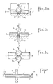
- FIG. 1a represents a section view of a tube 1 of ductile metal of small section, for example copper, but which can also be made of ductile steel, platinum, silver or gold, and of a length L such that these 2 ends 2.1 and 2.2 can be connected to a measuring device as described in figures 2 and 4.
- Said tube 1 is placed in a clamping means allowing it to be able to crush a small part of its length 1 so that the internal wall of the tube comes practically into contact with itself and can leave a free passage section 7 less than square micrometer.
- the latter is then crushed with the ball which is brought closer to anvil 4.1 by any clamping means 8 up to a distance d corresponding to the maximum sonic flow rate chosen, and following the calibration and the process already described above.
- This distance is a function of the thickness of said tube (ie at most equal to twice its thickness), operating pressures selected and the maximum flow required. If necessary, the deformed part is annealed between two tightening and calibration operations to stabilize the deformation obtained.
- FIG. 1b represents a sectional view of a second means of manufacturing, by crushing, of a flow regulator according to the invention: the tube 1 is in this example pinched between on one side a surface 4.2 forming an anvil and the other side a dihedral 5, which dihedral is brought closer to the surface 4.2 by any means 8 and as described in FIG. 1a.
- the surface 4.2 can be arbitrary it suffices that its intersection with the plane XX ′ passing through the edge of said dihedral and in which the displacement necessary for crushing takes place, is a convex line with radius of curvature greater than that of said tube 1.
- the advantage of using such a dihedral crushing means and that the length 1 thus pinched is small, or the smaller it is, the smaller the passage section 7 and the more the sonic operating range of the nozzle thus formed is broad.
- Figure 1c shows a sectional view of another means of manufacture, by crushing the tube 1 between on one side a roller 6.1, and on the other side a second roller 6.2; in fact, this second roller can be replaced by any surface making a stop and whose intersection with the plane YY ′ passing through the roller axis 6.1 and in which the displacement necessary for crushing takes place, is a convex line radius of curvature greater than that of said tube (1).
- Any clamping means 8 allows the rollers 6.1 and 6.2 to be brought together and the calibration manufacturing method already described previously is applied as in FIGS. 1a and 1b.
- the three crushing means above are not limiting and are cited by way of example: it is indeed possible to crush the tube also either by an annular constriction created by hydraulic pressure or the circular displacement of a roller either by several geometric shapes, such as 4 cylinders parallel to the axis of said tube.
- FIG. 2 represents a regulator assembly produced for example according to one of the methods described in FIGS. 1a, 1b, 1c, which regulator consists of the tube 1 of which a part 7 is crushed to constitute the sonic flow nozzle and all connection means 9 for example an ultra-high vacuum flange with metal seals.
- This flange 9 ensures on the one hand the tightness around the tube 1 and on the other hand allows the assembly of the assembly on any measurement circuit as described in FIG. 4; this flange can be mounted prior to the clamping operation on the tube and at a sufficient distance from the end 2.1 to allow said clamping and crushing operation.
- the other end 2.2 is connected to a supply of pressurized gas 10 to be sent at constant flow rate into the enclosure 11 where the pressure and adsorption volume measurements are made.
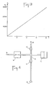
- FIG. 3 shows an example of a pressure curve obtained by mounting a flow regulator as described and produced according to the method of the present invention on a continuous volumetric apparatus allowing adsorption desorption measurements.
- the pressure P10 upstream of supplying a regulator with nitrogen and for the use selected for this test is 350,000 pascals and the volume of the enclosure 11 closed in which the vacuum was previously produced and then in which is sent the gas flow rate according to the description of Figure 2 is 25 cm3: the curve of Figure 3 then gives the pressure increase P11 as a function of time T expressed in hours; this is perfectly regular, therefore proving that the flow rate is indeed constant and stable; this is 0.25 mm3 / sec and in fact remains constant at 0.5% close to the maximum variation for the upstream pressure P10 retained for use of 350,000 Pa and for a downstream pressure P11 varying from 0 to 30,000 Pa.
- FIG. 4 represents a diagram of assembly of a sonic regulator in a known measuring device for gas desorption adsorption that is as simple as one can imagine.
- This device comprises in a known manner: - a vial 12 containing a sample of the adsorbent material and maintained at the desired temperature (by example 77 K for nitrogen adsorption for a specific area determination by the BET method (Brunauer-Emmett-Teller) known as written in the recommendations of the IUPAC (Union Internale de Chimie Pure and Applied) for the presentation of gas adsorption data.
- An absolute pressure sensor 13 allowing continuous recording of the quasi-equilibrium pressure.
- a regulator 14 supplied with adsorbable gas under constant pressure 10.
- This pressure should, in theory at least equal (and, in practice, higher) to the quotient of the maximum downstream pressure by the "critical ratio" corresponding to the transition from sub regime -sonic at the sonic flow regime for the gas considered.
- Said regulator 14 or constant flow meter is a regulator such as for example that described in FIG. 2 and to ensure a chosen maximum flow comprised between 0.25 and 25 mm 3 / sec, constant at 1% near maximum variation for a pressure downstream in said apparatus or device varying from 0 to 100,000 Pa. - a reference volume 15 (or device volume) of constant value and limited by the regulator 14, the pressure sensor 13 and the valves 16 and 17.
- the plotting of an adsorption isotherm is as follows: - At the start, the bulb 12 containing the adsorbent is under vacuum and the valve 16 is closed. - The valve 17 (towards the vacuum 18) is open and creates in the reference volume 15 a dynamic vacuum with an initial residual pressure Pi resulting from a balance between the flow of gas entering through the regulator 14 (the pressure upstream of the latter being kept constant by a suitable pressure regulator) and the gas flow pumped through the valve 17. - This pressure Pi is measured, as well as the temperature at which the volume 15 is maintained and the amount of initial gas present in this volume is deduced therefrom. - The pressure signal as a function of time is recorded on a graphic recorder or in the memory of a microcomputer.
- An interesting application of the device described in FIG. 4 is the rapid measurement of specific area by the BET method with nitrogen which uses the known method known as "at 1 point". Instead of determining the 3 to 5 points of the adsorption isotherm generally recommended for the application of the method, only one point of the isotherm is determined for a chosen equilibrium pressure. a priori in the vicinity of one third of the saturated vapor pressure of nitrogen (itself close to 100,000 Pa at the usual temperature of adsorption). By making the double assumption that the adsorption energy is high on the first layer and that the BET equation applies correctly on all this first part of the isotherm (of which we only know one point) we end up with a value of the specific area.
- This value can differ by several tens of% from that which is calculated using several points of the adsorption isotherm, especially when it turns out that the BET equation only applies to a limited portion of the isotherm or when the adsorption energy is not much higher on the first layer than on the following (as is the case for nitrogen adsorption on organic polymers or for the adsorption of argon - also usable for the BET method - on very many).
- the device according to the invention allows the following procedure:
- the adsorbable gas is introduced at a constant but relatively rapid speed until the pressure for forming the monolayer is reached as it has was determined in the previous paragraph.
- the introduction is stopped and waiting for the desired balance to be obtained, characterized by a predetermined value of the slope of the recording of the pressure as a function of time. Ideally, this slope should be chosen to be zero, but the time requirements lead to assigning it a finite value (for example: variation of the pressure read less than 1/1000 of its value over 30 seconds).
- the quantity then adsorbed is most often not discernible from that which would be adsorbed for a perfect balance, itself difficult to achieve in all rigor since it supposes the total overpressure of any temperature fluctuation of the volumetric apparatus ( whatever it is), any fluctuation in the level of the cryogenic bath making it possible to maintain the temperature of the adsorbent and any variation in atmospheric pressure capable of modifying the boiling temperature of the latter.
- the quantity adsorbed at this instant is determined, the final equilibrium pressure necessarily being a little lower than the exact pressure for forming the monolayer.
- the duration of the routine experiment may typically be, after cooling of the adsorbent, from 5 to 10 minutes to obtain the final adsorption equilibrium, ie a duration of the order of 1/4 d time, as expected from a quick routine measurement.
- Another interesting use of the regulating device according to the invention relates to gas desorption measures.
- the operation of the flow rate regulator at sonic flow speed according to the invention is different for a desorption experiment, itself necessary, mainly in the case of nitrogen, for the evaluation of the size distribution of the mesopores ( pore opening between 2 and 50 nm). These pores play an important role in most adsorbents of technological interest (excluding molecular sieves, all of whose pores, less than 2 nm, can then be studied from the single adsorption branch of the isothermal).
- the size of the mesopores is deduced from the relation (based on Kelvin's law) which links the pressure at which a given category of pores empties (in desorption) with the radius of curvature of the liquid meniscus located at the opening of these pores (provided that they have previously been saturated with adsorbable by capillary condensation).
Landscapes
- Chemical & Material Sciences (AREA)
- General Physics & Mathematics (AREA)
- Physics & Mathematics (AREA)
- Biochemistry (AREA)
- Life Sciences & Earth Sciences (AREA)
- Analytical Chemistry (AREA)
- Health & Medical Sciences (AREA)
- General Health & Medical Sciences (AREA)
- Dispersion Chemistry (AREA)
- Immunology (AREA)
- Pathology (AREA)
- Engineering & Computer Science (AREA)
- Automation & Control Theory (AREA)
- Measuring Volume Flow (AREA)
- Separation Of Gases By Adsorption (AREA)
Abstract
La présente invention a pour objet des dispositifs, des applications et des procédés de fabrication d'un régulateur capable d'assurer de très faible débit à vitesse d'écoulement sonique pour des mesures d'adsorption et de désorption gazeux. Le dispositif de régulation suivant l'invention comporte un tube (1) de métal ductile dont une faible partie de sa longueur est écrasée de telle façon que la paroi interne dudit tube est en contact sur elle-même, lequel tube est monté sur un moyen (9) de raccordement assurant l'étanchéité autour de celui-ci et son montage dans tout appareil de mesure d'adsorption désorption gazeuse, de telle façon qu'il assure l'alimentation continue d'un très faible débit gazeux entre 0,025 et 25 mm3/sec maximum à vitesse d'écoulement sonique malgré une contre pression variable.The present invention relates to devices, applications and methods for manufacturing a regulator capable of ensuring very low flow rate at sonic flow speed for gas adsorption and desorption measurements. The regulating device according to the invention comprises a tube (1) of ductile metal of which a small part of its length is crushed so that the internal wall of said tube is in contact with itself, which tube is mounted on a means (9) of connection ensuring the tightness around it and its mounting in any gas desorption adsorption measuring device, so that it ensures the continuous supply of a very low gas flow rate between 0.025 and 25 mm3 / sec maximum at sonic flow speed despite variable back pressure.
Description
La présente invention a pour objet des dispositifs, des applications et des procédés de fabrication d'un régulateur capable d'assurer de très faible débit à écoulement sonique pour des mesures d'adsorption et de désorption gazeuses.The present invention relates to devices, applications and methods for manufacturing a regulator capable of ensuring very low sonic flow rate for gas adsorption and desorption measurements.
Le secteur technique de l'invention est celui de la fabrication de matériel de mesure de volumétrie gazeuse. Une application de l'invention est la détermination de l'aire spécifique d'un adsorbant par l'introduction continue de gaz adsorbable avec une très grande précision.The technical sector of the invention is that of the manufacture of gas volume measurement equipment. An application of the invention is the determination of the specific area of an adsorbent by the continuous introduction of adsorbable gas with very high precision.
Il est connu en effet, que l'adsorption gazeuse (rétention des gaz à la surface) par les solides poreux ou divisés (tels que catalyseurs, adsorbants de purification ou de séparation des gaz ou des liquides, pigments, liants hydrauliques, charges pour caoutchouc ou plastiques, poudres phytosanitaires etc...) est un phénomène très exploité pour caractériser l'état de surface, le degré de division et la porosité de ces solides. Les gaz utilisés pour ces caractérisations sont tantôt chimisorbés (en particulier H2, CO, NH3, O2 ainsi que divers hydrocarbures) tantôt physisorbés (en particulier N2, Ar, Kr, CO2, H2O). La quantification et l'exploitation du phénomène d'adsorption passe toujours par la détermination des isothermes d'adsorption plus ou moins complète, c'est-à-dire les courbes donnant, à une température donnée, la quantité de gaz adsorbée à l'équilibre en fonction de la pression de ce gaz au-dessus de l'adsorbant ; lorsque le gaz peut donner lieu à une condensation tridimensionnelle à la température de l'expérience, on exprime habituellement la pression d'équilibre par rapport à la pression de vapeur saturante à cette température et on parle de pression relative d'équilibre.It is known, in fact, that gas adsorption (retention of gases at the surface) by porous or divided solids (such as catalysts, adsorbents for purifying or separating gases or liquids, pigments, hydraulic binders, fillers for rubber or plastics, phytosanitary powders, etc.) is a phenomenon that is widely used to characterize the surface condition, the degree of division and the porosity of these solids. The gases used for these characterizations are sometimes chemisorbed (in particular H2, CO, NH3, O2 as well as various hydrocarbons) sometimes physisorbed (in particular N2, Ar, Kr, CO2, H2O). The quantification and exploitation of the adsorption phenomenon always involves the determination of more or less complete adsorption isotherms, that is to say the curves giving, at a given temperature, the quantity of gas adsorbed at equilibrium as a function of the pressure of this gas above the adsorbent; when the gas can give rise to three-dimensional condensation at the temperature of the experiment, the equilibrium pressure is usually expressed in relation to the saturated vapor pressure at this temperature and we speak of relative equilibrium pressure.
La détermination de la quantité de gaz adsorbée se fait habituellement soit par volumétrie gazeuse, soit par gravimétrie soit encore par mesure des variations de concentration du gaz adsorbable dans un gaz vecteur, à l'aide d'un détecteur catharométrique. Ces trois méthodes sont habituellement utilisées pour une détermination discontinue d'un nombre limité de points de l'isotherme d'adsorption. On a cherché depuis longtemps à éviter les limitations de cette procédure discontinue (limitations en résolution et limitations en commodité expérimentale) par l'utilisation d'une procédure d'introduction lente et continue du gaz adsorbable.The quantity of adsorbed gas is usually determined either by gas volumetry, or by gravimetry, or again by measuring variations in the concentration of the adsorbable gas in a carrier gas, using a catharometric detector. These three methods are usually used for a discontinuous determination of a limited number of points of the adsorption isotherm. It has long been sought to avoid the limitations of this discontinuous procedure (limitations in resolution and limitations in experimental convenience) by the use of a procedure of slow and continuous introduction of the adsorbable gas.
Une telle procédure a été notamment utilisée par Monsieur W.B INNES tel que décrit dans la publication Analatical Chimistry en 1951 , 23 p 759 à 763 mais à un débit de l'ordre de 66 mm3 par seconde (aux conditions normales de température et de pression) qui s'avère bien trop rapide, la plupart du temps, pour assurer des conditions de quasi-équilibre, c'est-à-dire telles qu'à tout instant la presion mesurée "au vol" au-dessus de l'adsorbant coïncide, dans des limites fixées à l'avance et dépendant de la qualité de mesure souhaitée (par exemple, à 1 % près) avec la pression d'équilibre thermodynamique vers laquelle on tendrait après avoir arrêté, à cet instant même, l'introduction de gaz adsorbable supplémentaire. Cette procédure d'introduction lente et continue du gaz adsorbable a été utilisée avec succès en gravimétrie d'adsorption, tel que décrit dans la publication "Progress in Vaccum micro balance Techniques" vol 3 édité par C.EYRAUD et ESCOUBES p 83 à 92, en 1975, avec recherche des conditions correctes de quasi-équilibre et avec des vitesses d'adsorption non constantes mais aussi faibles que 0,07 mm3/sec, donc mille fois plus faibles que dans les travaux précédemment cités. Cette procédure a été utilisée en volumétrie d'adsorption tel que décrit dans la Revue Générale de Thermique n 171 de 1976 p 257 à 241 et a permis, dans certaines conditions, d'obtenir des vitesses d'introduction constantes du gaz adsorbable comprises entre 1,7 et 3,4 mm3/sec pour le tracé continu des isothermes d'adsorption d'azote sur des gels de silice. Cette procédure continue a été également utilisée, en gravimétrie d'adsorption pour le tracé complet d'isothermes d'adsorption-désorption d'azote ou de vapeur d'eau, tel que décrit dans la Revue Thermochimica Acta en 1978, 24 p 391 à 397.Such a procedure was used in particular by Mr. WB INNES as described in the publication Analatical Chemistry in 1951, 23 p 759 to 763 but at a flow rate of the order of 66 mm3 per second (under normal temperature and pressure conditions) which proves to be much too rapid, most of the time, to ensure conditions of quasi-equilibrium, that is to say such that at all times the pressure measured "on the fly" above the adsorbent coincides , within limits fixed in advance and dependent on the quality of measurement desired (for example, to within 1%) with the thermodynamic equilibrium pressure towards which one would tend after having stopped, at this very moment, the introduction of additional adsorbable gas. This procedure of slow and continuous introduction of the adsorbable gas has been successfully used in adsorption gravimetry, as described in the publication "Progress in Vaccum micro balance Techniques"
Différents brevets ont été pris sur les procédés et méthodes d'analyses ci-dessus, ainsi que sur du matériel permettant d'appliquer ces procédés et ces méthodes, on peut citer en particulier les brevets concernant les méthodes discontinues, tel que celui de Micrométrics Instrument déposé aux USA le 8/04/68 sous le n US 719562 et étendu à la France ensuite, celui d'EURATUM déposé le 10/12/69 sous le n LU 59979, et celui du laboratoire des Ponts et Chaussées déposé le 18/5/83 sous le n FR 8308242 ; en ce qui concerne la méthode continue, la Société OMICRON Technology Corporation a déposé un brevet le 9/9/1982 sous le n US 416164, non étendu à l'Europe, et qui reprend même dans ses revendication la méthode générale et certaines méthodes particulières décrites pourtant dans les publications ci-dessus et antérieures et exposant l'état de la technique en la matière.Various patents have been taken on the methods and methods of analysis above, as well as on equipment making it possible to apply these methods and these methods, one can quote in particular the patents concerning the discontinuous methods, such as that of Micrometrics Instrument filed in the USA on 8/04/68 under the number US 719562 and extended to France thereafter, that of EURATUM filed on 10/12/69 under the number LU 59979, and that of the laboratory of Bridges and Roads filed on 18 / 5/83 under FR 8308242; with regard to the continuous method, the Company OMICRON Technology Corporation deposited a patent on 9/9/1982 under n US 416164, not extended to Europe, and which even includes in its claims the general method and certain particular methods described however in the above and previous publications and setting out the state of the art in the matter.
En effet, l'idée d'une adsorption à vitesse très lente et éventuellement constante a séduit de nombreux chercheurs depuis plusieurs années car elle permet de tracer une isotherme d'adsorption de façon continue avec une infinité de points de quasi-équilibre et donc d'améliorer les mesures et en particulier en déduire l'aire spécifique avec plus de précisions ; de nombreux essais ont été ainsi réalisés et exposés depuis 1976 pour améliorer cette méthode la plus interessante et la plus demandée à ce jour. Cependant l'amélioration des mesures obtenues se heurtait jusqu'à la présente invention à la nécessite d'opérer à des débits d'adsorption compris entre 0,03 et 3 mm3 (aux conditions normales de température et de pression : TPN) par seconde afin d'assurer les conditions de quasi-équilibres satisfaisantes : il est en effet difficile d'une part d'obtenir un tel débit, d'autre part de le garder stable pendant la durée d'une expérience (entre 15 min et 15 h) compte tenu des variations de la pression atmosphérique et de l'augmentation de la pression de quasi-équilibre en cours de l'adsorption, et enfin de pouvoir le mesurer.Indeed, the idea of an adsorption at very slow and possibly constant speed has attracted many researchers for several years because it allows to trace an adsorption isotherm continuously with an infinity of quasi-equilibrium points and therefore d '' improve the measures and in particular deduce the specific area with more details; numerous attempts have been made and exposed since 1976 to improve this most interesting and most requested method to date. However, the improvement in the measurements obtained encountered, up to the present invention, the need to operate at adsorption flow rates of between 0.03 and 3 mm 3 (at normal temperature and pressure conditions: TPN) per second in order to to ensure satisfactory quasi-equilibrium conditions: it is indeed difficult to on the one hand to obtain such a flow, on the other hand to keep it stable for the duration of an experiment (between 15 min and 15 h) taking into account the variations of the atmospheric pressure and the increase in the pressure of almost balance during adsorption, and finally to be able to measure it.
Divers moyens sont utilisables, à ce jour, pour assurer ce faible débit : vannes de fuite réglables de haute précision telles que celles qu'on utilise pour l'étalonnage des spectomètres de masse, filtres de poudre métallique frittée, tubes capillaires étirés (de verre ou de métal), diaphragmes percés au laser à un diamètre de l'ordre du ![]()
![]()
Une manière connue d'obtenir un faible débit constant même avec une variation de pression aval possible et de réaliser un régulateur dans lequel la vitesse des molécules de gaz est sonique : pour cela il est connu qu'il suffit que le rapport de pression amont et aval, de part et d'autre de l'orifice du régulateur soit supérieur à un certain rapport critique, au-delà duquel le débit n'est alors proportionnel qu'au diamètre dudit orifice et à la pression seule amont. Il a été réalisé ainsi des régulateurs soniques de microdébit gazeux en perçant au laser, à un diamètre inférieur au micromètre une lame d'acier inoxydable ou tout autre matériau, y compris un rubis. Malheureusement la résistance à l'écoulement des gaz créée par ses orifices, qui s'ils sont de faible diamètre sont alors également de faible épaisseur, est trop faible pour permettre des performances de précision, de stabilité de débit et de faible gamme de microdébits.One known way of obtaining a constant low flow even with a possible downstream pressure variation and of producing a regulator in which the speed of the gas molecules is sonic: for this it is known that it is sufficient that the upstream pressure ratio and downstream on either side of the regulator orifice is greater than one certain critical ratio, beyond which the flow rate is then proportional only to the diameter of said orifice and to the only upstream pressure. Sonic regulators of gas micro-flow have been produced by drilling with a laser, to a diameter less than a micrometer, a blade of stainless steel or any other material, including a ruby. Unfortunately, the resistance to the flow of gases created by its orifices, which if they are small in diameter are then also thin, is too low to allow performance of precision, stability of flow rate and low range of micro-flows.
Le problème posé est de pouvoir réaliser un régulateur sonique de débit gazeux, permettant un débit aussi faible et stable que 0,03 mm3/sec, et restant constant avec une précision meilleure que 1 % pour une pression amont fixe et constante, et une pression aval variant entre le vide et le dixième au moins de la pression amont.The problem is to be able to produce a sonic gas flow regulator, allowing a flow as low and stable as 0.03 mm3 / sec, and remaining constant with an accuracy better than 1% for a fixed and constant upstream pressure, and a pressure downstream varying between vacuum and at least a tenth of the upstream pressure.
Une solution au problème posé est un dispositif comportant un régulateur de faible débit gazeux à vitesse d'écoulement sonique utilisable dans tout appareil connu de mesures d'adsorption et de désorption gazeuxe, caractérisé en ce qu'il est constitué d'un tube de métal ductile de faible section, par exemple en cuivre, dont une faible partie de sa longueur est écrasée de telle façon que la paroi interne dudit tube est en contact sur elle-même, lequel tube est monté sur un moyen de raccordement assurant d'une part l'étanchéité autour de celui-ci, et d'autre part son montage dans ledit appareil de mesure d'adsorption et de désorption gazeuse, de telle façon qu'il assure l'alimentation continue d'un très faible débit gazeux dans cet appareil malgré une contre pression variable dans celui-ci entre le vide et au moins le dixième de la pression amont d'alimentation.One solution to the problem posed is a device comprising a regulator of low gas flow rate with a sonic flow rate usable in any known device for gas adsorption and desorption measurements, characterized in that it consists of a metal tube. ductile of small cross section, for example copper, of which a small part of its length is crushed so that the internal wall of said tube is in contact with itself, which tube is mounted on a connection means ensuring on the one hand the seal around it, and on the other hand its mounting in said gas adsorption and desorption measuring device, so that it ensures the continuous supply of a very low gas flow rate in this device despite a variable back pressure therein between the vacuum and at least one tenth of the upstream supply pressure.
Une autre solution au problème posé est un procédé de fabrication d'un régulateur de très faible débit gazeux à vitesse d'écoulement sonique utilisable dans tout appareil connu de mesures d'adsorption et de désorption gazeuse fonctionnant à des pressions d'utilisation données et dans lequel on veut introduire un gaz à un débit très faible choisi, caractérisé en ce que :
- on prend un tube de métal ductile de faible section par exemple en cuivre d'une épaisseur de paroi suffisamment forte pour supporter lesdites différences de pression gazeuse d'utilisation ;
- on monte ledit tube sur un moyen de raccordement assurant d'une part l'étanchéité autour de celui-ci, et d'autre part son montage dans ledit appareil, lequel moyen est montée près d'une extrémité dudit tube à distance suffisante pour permettre l'opération suivante qui peut être réalisée également préalablement ;
- on écrase ledit tube sur une faible longueur entre ladite bride et l'extrémité correspondante ci-dessus ;
- on branche ledit moyen de raccordement et ledit tube sur tout appareil de volumétrie étalonné et connu, et on envoie un gaz à une pression donnée d'étalonnage par une extrémité du tube et on mesure par exemple l'augmentation de pression dans le volume connu où débouche l'autre extrémité et dont la pression initiale est choisie en fonction de la plage d'étalonnage retenue et de la pression amont du gaz envoyé ;
le sens de passage du gaz dans le débit mètre est indifférent, de l'extrémité pincée vers l'extrémité non pincée ou inversement, le premier sens de passage est préférable pour des pressions amonts élevés.
- on détermine en continu le débit ainsi obtenu et on vérifie que celui-ci est constant et correspond au plus à la valeur choisie sur toute la plage de mesures de la variation de la pression aval voulue et si ce n'est pas le cas on continue l'opération d'écrasement en augmentant légèrement le pincement du tube et on vérifie l'étalonnage jusqu'à obtenir au plus le débit souhaité compte tenu desdites pressions d'utilisation retenues initialement.Another solution to the problem posed is a method of manufacturing a regulator of very low gas flow rate at sonic flow rate usable in any known device for gas adsorption and desorption measurements operating at given operating pressures and in which one wants to introduce a gas at a very low chosen flow rate, characterized in that:
- We take a ductile metal tube of small section, for example copper with a wall thickness sufficiently strong to support said differences in gas pressure of use;
- Said tube is mounted on a connection means ensuring on the one hand the seal around it, and on the other hand its mounting in said device, which means is mounted near one end of said tube at sufficient distance to allow the following operation which can also be carried out beforehand;
- Said tube is crushed over a short length between said flange and the corresponding end above;
- Connect said connection means and said tube to any calibrated and known volumetric device, and send a gas at a given calibration pressure through one end of the tube and measure for example the pressure increase in the known volume where the other end opens and the initial pressure of which is chosen as a function of the calibration range used and the upstream pressure of the gas sent;
the direction of passage of the gas in the flow meter is indifferent, from the pinched end to the non-pinched end or vice versa, the first direction of passage is preferable for high upstream pressures.
- the flow rate thus obtained is continuously determined and it is checked that it is constant and corresponds at most to the value chosen over the whole range of measurements of the desired downstream pressure variation and if this is not the case, continues the crushing operation by slightly increasing the nipping of the tube and the calibration is checked until the desired flow rate is obtained at the most, taking into account said operating pressures initially retained.
Le résultat est un nouveau procédé de fabrication d'un nouveau régulateur sonique pouvant assurer de très faibles débits pour des mesures d'adsorption et de désorption gazeuse.The result is a new manufacturing process for a new sonic regulator that can provide very low flow rates for gas adsorption and desorption measurements.
Les avantages d'un tel procédé et d'un tel régulateur sont multiplies car ils permettent de réaliser des mesures d'une très grande précision sur de grandes gammes de pression, et de fabriquer des régulateurs d'une manière très fiable, sûre et peu onéreuse. En effet, le matériel de base est simple à trouver en utilisant tout type de matériau ductile, tel que le cuivre qui est le moins couteux, mais aussi de l'argent ou de l'or, et la mise en oeuvre du procédé de fabrication est facile à réaliser : seul l'étalonnage demande quelques précautions mais on utilise pour cela les appareils de mesure connu, de mesure volumétrique et de pression. De plus il n'y a pas à priori de limite maximale à la résistance qu'oppose, à l'écoulement des gaz de tel régulateur à tuyere pincée, ni de limite maximum d'épaisseur de paroi du tube en sorte qu'il est possible d'appliquer en amont si nécessaire, une pression de plusieurs MPa afin d'étendre le domaine du régime sonique en fonction de la pression aval.The advantages of such a method and of such a regulator are multiplied because they make it possible to carry out very precise measurements over large pressure ranges, and to manufacture regulators in a very reliable, safe and inexpensive manner. expensive. Indeed, the basic material is simple to find by using any type of ductile material, such as copper which is the least expensive, but also silver or gold, and the implementation of the manufacturing process. is easy to perform: only calibration requires a few precautions, but we use known measuring, volumetric and pressure measuring devices for this. In addition there is a priori no maximum limit to the resistance that opposes the flow of gases from such a pinched nozzle regulator, nor a maximum limit of wall thickness of the tube so that it is possible to apply upstream if necessary, a pressure of several MPa in order to extend the range of the sonic regime as a function of the downstream pressure.
L'utilisation de tel régulateur à très faible débit, soit de 0,025 à 25 mm3/sec, avec une bonne stabilité, remplace donc avantageusement tout type de débitmètre connu et rappelé précédemment, qui sont très sophistiqués avec des contrôles et des régulations électroniques et qui de toute façon ont un seuil de détection limite, du au principe même de leur conception, qui est au-dessus de ce qui est souhaitable pour une bonne mesure en quasi-équilibre continu de pression pour un isotherme d'adsorption ; seuls les régulateurs réalisés par le procédé de la présente invention répondent à ces critères. Il offrent aussi la possibilité de réaliser des appareils de mesure très performants avec lesquels on peut alors élaborer diverses procédures et méthodes de mesure très précises et fiables, telle que la mesure rapide de l'aire spécifique ou la mesure de désorption gazeuse.The use of such a regulator with very low flow rate, that is from 0.025 to 25
La description suivante se réfère aux dessins annéxés, qui représentent, sans aucun caractère limitatif, des exemples de réalisation suivant les procédés et les dispositifs de l'invention, et qui sont donnés à titre d'illustration mais d'autres réalisations et applications peuvent être envisagées.
- La figure 1a représente une vue en coupe d'un moyen de fabrication avec une bille.
- La figure 1b représente une vue en coupe d'un moyen de fabrication par écrasement avec un dièdre.
- La figure 1c représente une vue en coupe d'un moyen de fabrication par écrasement avec un ou deux rouleaux.
- La figure 2 représente un montage d'un régulateur sur une bride.
- La figure 3 représente un exemple de courbe de pression.
- La figure 4 représente un schéma de montage d'un régulateur dans un appareil de mesure d'adsorption desorption gazeuse.
- Figure 1a shows a sectional view of a manufacturing means with a ball.
- Figure 1b shows a sectional view of a means of manufacture by crushing with a dihedral.
- Figure 1c shows a sectional view of a means of manufacturing by crushing with one or two rollers.
- Figure 2 shows a mounting of a regulator on a flange.
- Figure 3 shows an example of a pressure curve.
- FIG. 4 shows a diagram of the mounting of a regulator in a gas desorption adsorption measuring device.
La figure 1a représente une vue en coupe d'un tube 1 de métal ductile de faible section, par exemple en cuivre, mais pouvant être aussi en acier ductile, en platine, en argent ou en or, et d'une longueur L telles que ces 2 extrémités 2.1 et 2.2 puisse être raccordées à un appareil de mesure tel que décrit dans les figures 2 et 4.FIG. 1a represents a section view of a
On place ledit tube 1 dans un moyen de serrage permettant de pouvoir écraser une faible partie de sa longueur 1 de façon à ce que la paroi interne du tube vient pratiquement en contact sur elle-même et puisse laisser une section de passage 7 libre inférieure au micromètre carré. Pour cela on peut utiliser d'un côté une bille 3 de diamètre supérieure à la largeur du tube 1, ou à son diamètre si celui-ci est un cylindre (d'autres formes de sections peuvent être envisagées), et de l'autre côté une enclume 4.1 contre laquelle on place ledit tube 1 : on écrase alors celui-ci avec la bille qu'on rapproche de l'enclume 4.1 par tout moyen de serrage 8 jusqu'à une distance d correspondant au débit sonique maximum choisi, et suivant l'étalonnage et le procédé déjà décrit précédemment. Cette distance est fonction de l'épaisseur dudit tube (soit au plus égale au double de celle-ci), des pressions d'utilisation retenue et du débit maximum voulu. Si nécessaire on recuit la partie déformée entre deux opérations de serrage et d'étalonnage pour stabiliser la déformation obtenue.Said
La figure 1b représente une vue en coupe d'un deuxième moyen de fabrication, par écrasement, d'un régulateur de débit suivant l'invention : le tube 1 est dans cet exemple pincé entre d'un côté une surface 4.2 faisant enclume et de l'autre côté un dièdre 5, lequel dièdre est rapproché de la surface 4.2 par tout moyen 8 et tel que décrit dans la figure 1a. La surface 4.2 peut être quelconque il suffit que son intersection avec le plan XX′ passant par l'arête dudit dièdre et dans lequel s'effectue le déplacement nécessaire à l'écrasement, est une ligne convexe de rayon de courbure supérieur à celui dudit tube 1 . L'avantage d'utiliser un tel moyen d'écrasement par dièdre et que la longueur 1 ainsi pincée est petite, or plus celle-ci est faible, plus la section de passage 7 est faible et plus le domaine de fonctionnement sonique de la tuyère ainsi formée est large.FIG. 1b represents a sectional view of a second means of manufacturing, by crushing, of a flow regulator according to the invention: the
La figure 1c représente une vue en coupe d'un autre moyen de fabrication, par écrasement du tube 1 entre d'un côté un rouleau 6.1 , et de l'autre côté un deuxième rouleau 6.2 ; en fait, ce deuxième rouleau peut être remplacé par toute surface faisant butée et dont l'intersection avec le plan YY′ passant par l'axe de rouleau 6.1 et dans lequel s'effectue le déplacement nécessaire à l'écrasement, est une ligne convexe de rayon de courbure supérieur à celui dudit tube (1). Tout moyen de serrage 8 permet de rapprocher les rouleaux 6.1 et 6.2 et on applique alors le procédé de fabrication d'étalonnage déjà décrit précédemment comme pour les figures 1a et 1b.Figure 1c shows a sectional view of another means of manufacture, by crushing the
Les trois moyens d'écrasement ci-dessus ne sont pas limitatifs et sont cités à titre d'exemple : on peut en effet assurer l'écrasement du tube également soit par une constriction annulaire créée par une pression hydraulique ou le déplacement circulaire d'un rouleau, soit par plusieurs formes géométriques, tel que 4 cylindres parallèles à l'axe dudit tube.The three crushing means above are not limiting and are cited by way of example: it is indeed possible to crush the tube also either by an annular constriction created by hydraulic pressure or the circular displacement of a roller either by several geometric shapes, such as 4 cylinders parallel to the axis of said tube.
La figure 2 représente un montage de régulateur réalisé par exemple suivant l'une des méthodes décrites dans les figures 1a, 1b, 1c, lequel régulateur est constitué du tube 1 dont une partie 7 est écrasée pour constituer la tuyère d'écoulement sonique et tout moyen de raccordement 9 par exemple une bride à ultravide à joints métalliques. Cette bride 9 assure d'une part l'étanchéité autour du tube 1 et d'autre part permet le montage de l'ensemble sur tout circuit de mesure tel que la décrit la figure 4 ; cette bride peut être montée préalablement à l'opération de serrage sur le tube et à une distance suffisante de l'extrémité 2.1 pour permettre ladite opération de serrage et d'écrasement.FIG. 2 represents a regulator assembly produced for example according to one of the methods described in FIGS. 1a, 1b, 1c, which regulator consists of the
L'autre extrémité 2.2 est raccordée à une alimentation de gaz sous pression 10 devant être envoyé à débit constant dans l'enceinte 11 où se font les mesures de volumétrie de pression et d'adsorption. On sait en effet que pour une vitesse subsonique des molécules de gaz dans la tuyère 7, le débit massique de ce gaz est :
dm/dt = k1 x S7 x √
où S7 est la section minimale de passage de la tuyère, k1 et une constante dépendant du facteur d'expansion du gaz, k2 est une autre constante dépendant de la densité du gaz sous la pression P10 amont, et P11 est la pression à la sortie de la tuyère 7. Il est possible en théorie d'éliminer partiellement l'incidence d'une variation de la pression aval P11 sur le débit massique en imposant un régime sonique tel que dans la région 7 de la tuyère les molécules atteignent la vitesse du son : pour cela il faut que le rapport P11/P10 des pressions aval et amont soit en-dessous d'un seuil critique qui est égal pour l'air à 0,53. Alors le débit massique s'écrit
dm / dt = k1 x S7 x √
where S7 is the minimum passage section of the nozzle, k1 and a constant depending on the gas expansion factor, k2 is another constant depending on the density of the gas under the upstream pressure P10, and P11 is the outlet pressure of the
La figure 3 représente un exemple de courbe de pression obtenue en montant un régulateur de débit tel que décrit et réalisé suivant le procédé de la présente invention sur un appareil de volumétrie continu permettant des mesures d'adsorption désorption. La pression P10 amont d'alimentation d'un régulateur avec de l'azote et pour l'utilisation retenue pour cet essai est de 350 000 pascals et le volume de l'enceinte 11 fermé dans lequel le vide a été réalisé préalablement puis dans lequel est envoyé le débit de gaz suivant la description de la figure 2 est de 25 cm3 : la courbe de la figure 3 donne alors l'augmentation de pression P11 en fonction du temps T exprimé en heure ; celle-ci est parfaitement régulière prouvant donc que le débit est bien constant et stable ; celui-ci est de 0,25 mm3/sec et reste en effet constant à 0,5 % près de variation maximum pour la pression P10 amont retenue d'utilisation de 350 000 Pa et pour une pression aval P11 variant de 0 à 30 000 Pa.FIG. 3 shows an example of a pressure curve obtained by mounting a flow regulator as described and produced according to the method of the present invention on a continuous volumetric apparatus allowing adsorption desorption measurements. The pressure P10 upstream of supplying a regulator with nitrogen and for the use selected for this test is 350,000 pascals and the volume of the
D'autres essais et réalisations peuvent être faites et on peut ainsi réaliser tout dispositif de mesure en continu d'adsorption et de désorption gazeuse avec un régulateur de microdébit suivant les caractéristiques et les procédés de la présente invention.Other tests and embodiments can be made and it is thus possible to produce any device for continuous measurement of gas adsorption and desorption with a microdebit regulator according to the characteristics and the methods of the present invention.
La figure 4 représente un schéma de montage d'un régulateur sonique dans un appareil de mesure connu d'adsorption désorption gazeuse le plus simple que l'on puisse imaginer. Cet appareil comprend d'une manière connue:
- une ampoule 12 contenant un échantillon du matériau adsorbant et maintenu à la température souhaitée (par exemple 77 K pour l'adsorption d'azote en vue d'une détermination d'aire spécifique par la méthode BET (Brunauer-Emmett-Teller) connue telle que d'écrite dans les recommandations d' l'IUPAC (Union Internale de Chimie Pure et Appliquée) pour la présentation des données de l'adsorption gazeuse.
- un capteur 13 de pression absolue permettant un enregistrement continu de la pression de quasi-équilibre.
- un régulateur 14 alimenté en gaz adsorbable sous pression constante 10. Cette pression devra être, en théorie au moins égale (et, en pratique, supérieure) au quotient de la pression aval maximale par le "rapport critique" correspondant au passage du régime sub-sonique au régime d'écoulement sonique pour le gaz considéré. Ledit régulateur 14 ou débimètre à débit constant est un régulateur tel que par exemple celui décrit dans la figure 2 et pour assurer un débit maximum choisi compris entre 0,25 et 25 mm3/sec, constant à 1 % près de variation maximum pour une pression aval dans ledit appareil ou dispositif variant de 0 à 100 000 Pa.
- un volume de référence 15 (ou volume d'appareil) de valeur constante et limité par le régulateur 14, le capteur de pression 13 et les vannes 16 et 17.FIG. 4 represents a diagram of assembly of a sonic regulator in a known measuring device for gas desorption adsorption that is as simple as one can imagine. This device comprises in a known manner:
- a
- An
- A
- a reference volume 15 (or device volume) of constant value and limited by the
Le tracé d'un isotherme d'adsorption s'effectue de la manière suivante :
- Au départ, l'ampoule 12 contenant l'adsorbant est sous vide et la vanne 16 est fermée.
- La vanne 17 (vers le vide 18) est ouverte et crée dans le volume de référence 15 un vide dynamique avec une pression initiale résiduelle Pi résultant d'un équilibre entre le flux de gaz entrant à travers le régulateur 14 (la pression en amont de celui-ci étant maintenue constante par un manodétendeur appoprié) et le flux de gaz pompé à travers la vanne 17.
- Cette pression Pi est mesurée, ainsi que la température à laquelle est maintenu le volume 15 et on en déduit la quantité de gaz initiale présente dans ce volume.
- On enregistre, sur enregistreur graphique ou dans la mémoire d'un micro-ordinateur, le signal de pression en fonction du temps.
- On prend comme origine du temps, sur cet enregistrement, l'instant où l'on cesse le pompage en fermant la vanne 17 et où l'on commence l'adsorption en ouvrant la vanne 16.
- L'enregistrement de pression de quasi-équilibre en fonction du temps, c'est-à-dire en fonction de la quantité de gaz introduite se convertit aisément, en tenant compte de la quantité de gaz non adsorbée (et qui est proportionnelle à la pression) en une isotherme d'adsorption donnant, en toute rigueur, la quantité de gaz adsorbée par gramme d'adsorbant en fonction de la pression de quasi-équilibre.The plotting of an adsorption isotherm is as follows:
- At the start, the
- The valve 17 (towards the vacuum 18) is open and creates in the reference volume 15 a dynamic vacuum with an initial residual pressure Pi resulting from a balance between the flow of gas entering through the regulator 14 (the pressure upstream of the latter being kept constant by a suitable pressure regulator) and the gas flow pumped through the
- This pressure Pi is measured, as well as the temperature at which the
- The pressure signal as a function of time is recorded on a graphic recorder or in the memory of a microcomputer.
- We take as the origin of time, on this recording, the instant when we stop pumping by closing the
- The recording of quasi-equilibrium pressure as a function of time, that is to say as a function of the quantity of gas introduced is easily converted, taking into account the quantity of gas not adsorbed (and which is proportional to pressure) into an adsorption isotherm giving, in all rigor, the quantity of gas adsorbed per gram of adsorbent as a function of the quasi-equilibrium pressure.
En cas de doute, la validité des conditions de quasi-équilibre choisies est facilement vérifiée par une deuxième expérience avec une vitesse d'adsorption plus lente (donc par exemple avec une masse plus grande d'adsorbant). Si les deux isothermes d'adsorption coïncident, c'est que la "vitesse spécifique d'adsorption" est satisfaisante dans les deux cas. Sinon, il est souhaitable d'opérer à vitesse plus lente. D 'où l'intérêt et la nécessité d'un régulateur de débit à vitesse sonique sans limitation du côté des débits les plus faibles.In case of doubt, the validity of the chosen quasi-equilibrium conditions is easily verified by a second experiment with a slower adsorption speed (therefore for example with a larger mass of adsorbent). If the two adsorption isotherms coincide, then the "specific adsorption speed" is satisfactory in both cases. Otherwise, it is desirable to operate at a slower speed. Hence the interest and the need for a flow regulator at sonic speed without limitation on the side of the lowest flow rates.
Dans une installation de dispositif telle que décrit dans la figure 4, il peut être monté plusieurs régulateurs de débit à vitesse sonique en parallèle avec des vannes d'isolation afin de disposer de plusieurs débits possibles d'introduction pour effectuer différentes mesures.In a device installation as described in FIG. 4, several sonic speed flow regulators can be mounted in parallel with isolation valves in order to have several possible introduction flow rates for carrying out different measurements.
Une application intéressante du dispositif décrit dans la figure 4 est la mesure rapide d'aire spécifique par la méthode BET à l'azote qui fait appel à la méthode connue dite "à 1 point". Au lieu de déterminer les 3 à 5 points de l'isotherme d'adsorption recommandés en général pour l'application de la méthode on ne détermine qu'un seul point de l'isotherme pour une pression d'équilibre choisie a priori au voisinage du tiers de la pression de vapeur saturante de l'azote (elle-même voisine de 100 000 Pa à la température habituelle de l'adsorption). En faisant la double hypothèse que l'énergie d'adsorption est élevée sur la première couche et que l'équation BET s'applique correctement sur toute cette première partie de l'isotherme (dont on ne connait qu'un point) on aboutit à une valeur de l'aire spécifique. Cette valeur peut différer de plusieurs dizaines de % de celle qu'on calcule à l'aide de plusieurs points de l'isotherme d'adsorption, surtout lorsqu'il s'avère que l'équation BET ne s'applique qu'à une portion limitée de l'isotherme ou lorsque l'énergie d'adsorption n'est pas beaucoup plus élevée sur la première couche que sur les suivantes (comme c'est le cas pour l'adsorption d'azote sur des polymères organiques ou pour l'adsorption d'argon -aussi utilisable pour la méthode BET- sur de très nombreux).An interesting application of the device described in FIG. 4 is the rapid measurement of specific area by the BET method with nitrogen which uses the known method known as "at 1 point". Instead of determining the 3 to 5 points of the adsorption isotherm generally recommended for the application of the method, only one point of the isotherm is determined for a chosen equilibrium pressure. a priori in the vicinity of one third of the saturated vapor pressure of nitrogen (itself close to 100,000 Pa at the usual temperature of adsorption). By making the double assumption that the adsorption energy is high on the first layer and that the BET equation applies correctly on all this first part of the isotherm (of which we only know one point) we end up with a value of the specific area. This value can differ by several tens of% from that which is calculated using several points of the adsorption isotherm, especially when it turns out that the BET equation only applies to a limited portion of the isotherm or when the adsorption energy is not much higher on the first layer than on the following (as is the case for nitrogen adsorption on organic polymers or for the adsorption of argon - also usable for the BET method - on very many).
Pour pallier à ces limitations de la "méthode BET à 1 point" mais en conserver la rapidité le dispositif suivant l'invention permet la procédure suivante :To overcome these limitations of the "1 point BET method" but to keep it fast, the device according to the invention allows the following procedure:
On détermine avec ledit dispositif, lors d'une étude préliminaire qui n'est à effectuer qu'une seule fois pour chaque type d'adsorbant (c'est-à-dire de nature chimique et de texture approximativement fixée. Par exemple : gel de silice d'aire spécifique comprise entre 10 et 200 m g-1, soufre pulvérulent d'aire spécifique comprise entre 1 et 50 m g-1, charbon actif d'aire spécifique apparente comprise entre 200 et 800 m g-1...) une isotherme d'adsorption en quasi-équilibre jusqu'à une pression égale à 40 % de la valeur saturante.It is determined with said device, during a preliminary study which is to be carried out only once for each type of adsorbent (that is to say of chemical nature and of approximately fixed texture. For example: gel silica with a specific area between 10 and 200 m g-1, powdered sulfur with a specific area between 1 and 50 m g-1, activated carbon with an apparent specific area between 200 and 800 m g-1 .. .) a quasi-equilibrium adsorption isotherm up to a pressure equal to 40% of the saturation value.
On applique les critères de validité de l'équation BET déjà connue, on détermine la région d'application correcte de cette équation (en termes de pression d'équilibre), on en déduit la quantité de gaz adsorbée pour constituer une monocouche, on relève la pression d'équilibre correspondante et la pente de l'isotherme d'adsorption en ce point. Ces deux dernières données sont à conserver en mémoire et à utiliser dans la procédure rapide ci-dessous, chaque fois qu'on étudiera un adsorbant du même type.We apply the validity criteria of the already known BET equation, we determine the correct region of application of this equation (in terms of equilibrium pressure), we deduce the amount of gas adsorbed to constitute a monolayer, we note the corresponding equilibrium pressure and the slope of the adsorption isotherm at this point. These last two data are to be kept in memory and to use in the quick procedure below, each time we study an adsorbent of the same type.
Pour chaque nouvel échantillon du même type que ci-dessus : on introduit, à l'aide du régulateur de débit sonique, le gaz adsorbable à vitesse constante mais relativement rapide jusqu'à atteindre la pression de formation de la monocouche telle qu'elle a été déterminée au paragraphe précédent.For each new sample of the same type as above: using the sonic flow regulator, the adsorbable gas is introduced at a constant but relatively rapid speed until the pressure for forming the monolayer is reached as it has was determined in the previous paragraph.
On cesse l'introduction et on attend l'obtention de l'équilibre désiré, caractérisé par une valeur prédéterminée de la pente de l'enregistrement de la pression en fonction du temps. Idéalement, cette pente devrait être choisie nulle mais les impératifs de temps conduisent à lui assigner une valeur finie (par exemple : variation de la pression lue inférieure au 1/1000 de sa valeur sur 30 secondes). La quantité alors adsorbée, n'est le plus souvent pas discernable de celle qui serait adsorbée pour un équilibre parfait, lui même difficile à atteindre en toute rigueur puisqu'il suppose la surpression totale de toute fluctuation de température de l'appareil de volumétrie (quel qu'il soit), de toute fluctuation de niveau du bain cryogénique permettant d'assurer le maintien de température de l'adsorbant et de toute variation de la pression atmosphérique susceptible de modifier la température d'ébullition de ce dernier.The introduction is stopped and waiting for the desired balance to be obtained, characterized by a predetermined value of the slope of the recording of the pressure as a function of time. Ideally, this slope should be chosen to be zero, but the time requirements lead to assigning it a finite value (for example: variation of the pressure read less than 1/1000 of its value over 30 seconds). The quantity then adsorbed, is most often not discernible from that which would be adsorbed for a perfect balance, itself difficult to achieve in all rigor since it supposes the total overpressure of any temperature fluctuation of the volumetric apparatus ( whatever it is), any fluctuation in the level of the cryogenic bath making it possible to maintain the temperature of the adsorbent and any variation in atmospheric pressure capable of modifying the boiling temperature of the latter.
On détermine la quantité adsorbée à cet instant, la pression d'équilibre finale étant obligatoirement un peu plus faible que la pression exacte de formation de la monocouche.The quantity adsorbed at this instant is determined, the final equilibrium pressure necessarily being a little lower than the exact pressure for forming the monolayer.
Grâce à la pente connue de l'isotherme d'adsorption, on ramène la quantité ci-dessus à celle qui serait adsorbée sous la pression exacte de formation de la monocouche pour cette catégorie d'échantillon.Thanks to the known slope of the adsorption isotherm, the above quantity is reduced to that which would be adsorbed under the exact pressure of formation of the monolayer for this category of sample.
Les avantages de cette procédure sont les suivants :
* l'introduction du gaz adsorbable à débit fini (ordres de grandeur commodes : 12 à 25 mm3/sec permet d'éviter les graves perturbations d'équilibre (parfois en partie irréversibles et génératrices d'erreur, parfois entraînant une mise à l'équilibre plus longue) introduites par la méthode de volumétrie discontinue conventionnelle.
* l'écart réel, mais modéré, à l'équilibre permet d'arrêter l'introduction à une pression pré-déterminée qui sera peu supérieure à la pression finale d'équilibre.
* il en résulte, grâce notamment à la correction possible à partir de la pente de l'isotherme, que la quantité nécessaire pour former la monocouche, selon une application non simplifiée de l'équation BET, est déterminée avec précision.
* il est toujours loisible, à titre de comparaison, d'exploiter par la procédure simplifiée dite "BET à 1 point" le point unique qui vient d'être déterminé sur l'isotherme d'adsorption, avec les limitations qui ont été rappelées ci-dessus.
* la durée de l'expérience de routine pourra être typiquement, après refroidissement de l'adsorbant, de 5 à 10 minutes pour l'obtention de l'équilibre d'adsorption final, soit une durée de l'ordre du 1/4 d'heure, comme on l'attend d'une mesure rapide de routine.
Une autre utilisation interessante du dispositif régulateur suivant l'invention concerne les mesures de désorption gazeuse.The advantages of this procedure are:
* the introduction of adsorbable gas at a finite flow rate (convenient orders of magnitude: 12 to 25 mm3 / sec makes it possible to avoid serious disturbances in equilibrium (sometimes partly irreversible and generating errors, sometimes causing longer equilibrium) introduced by the conventional discontinuous volumetric method.
* the real, but moderate, equilibrium deviation allows the introduction to be stopped at a predetermined pressure which will be little higher than the final equilibrium pressure.
* it follows, thanks in particular to the possible correction from the slope of the isotherm, that the quantity necessary to form the monolayer, according to a non-simplified application of the BET equation, is determined with precision.
* it is always possible, by way of comparison, to exploit the single point which has just been determined on the adsorption isotherm by the simplified procedure known as "1-point BET", with the limitations which have been mentioned below -above.
* the duration of the routine experiment may typically be, after cooling of the adsorbent, from 5 to 10 minutes to obtain the final adsorption equilibrium, ie a duration of the order of 1/4 d time, as expected from a quick routine measurement.
Another interesting use of the regulating device according to the invention relates to gas desorption measures.
L'exploitation du régulateur de débit à vitesse d'écoulement sonique suivant l'invention est différente pour une expérience de désorption, elle même nécessaire, principalement dans le cas de l'azote, pour l'évaluation de la distribution de taille des mésopores (ouverture des pores comprises entre 2 et 50 nm). Ces pores jouent un rôle important dans la plupart des adsorbants d'intérêt technologique (à l'exclusion des tamis moléculaires, dont tous les pores, inférieurs à 2 nm, peuvent alors être étudiés à partir de la seule branche d'adsorption de l'isotherme). La taille des mésopores se déduit de la relation (fondée sur la loi de Kelvin) qui lie la pression à laquelle se vide (en désorption) une catégorie donnée de pores avec le rayon de courbure du ménisque liquide situé à l'ouverture de ces pores (à condition qu'ils aient au préalable été saturés d'adsorbable par condensation capillaire).The operation of the flow rate regulator at sonic flow speed according to the invention is different for a desorption experiment, itself necessary, mainly in the case of nitrogen, for the evaluation of the size distribution of the mesopores ( pore opening between 2 and 50 nm). These pores play an important role in most adsorbents of technological interest (excluding molecular sieves, all of whose pores, less than 2 nm, can then be studied from the single adsorption branch of the isothermal). The size of the mesopores is deduced from the relation (based on Kelvin's law) which links the pressure at which a given category of pores empties (in desorption) with the radius of curvature of the liquid meniscus located at the opening of these pores (provided that they have previously been saturated with adsorbable by capillary condensation).
On peut utiliser un appareil connu semblable à celui qui est schématisé Fig 4 mais on impose cette fois en permanence le vide ou, en tout cas, dans le cas de l'azote, une pression inférieure à 20 000 Pascal en amont 10 qui devient alors l'aval du régulateur 14. L'expression déjà donnée du débit en régime sonique est =
On note que les expressions de débit sont données ici en valeur massique dans les équations, et en valeur volumique dans les chiffres, la conversion et la relation entre les deux étant connue en fonction de la densité des gaz utilisés, de leur température et de leur pression lors des essais.Note that the flow rate expressions are given here in mass value in the equations, and in volume value in the figures, the conversion and the relationship between the two being known as a function of the density of the gases used, their temperature and their pressure during testing.
La présente invention n'est pas limitée au mode de réalisation et aux applications décrites ci-dessus et qui ne constituent que des exemples auxquels des modifications et des variantes peuvent lêtre apportées.The present invention is not limited to the embodiment and to the applications described above and which constitute only examples to which modifications and variants can be made.
Claims (10)
- on prend un tube (1) de métal ductile de faible section par exemple en cuivre d'une épaisseur et d'une épaisseur de paroi suffisamment forte pour supporter les dites différents de pression gazeuse d'utilisation ;
- on monte ledit tube sur un moyen de raccordement (9) assurant d'une part l'étanchéité autour de celui-ci, et d'autre part son montage dans ledit appareil, lequel moyen est montée près d'une extrémité (2) dudit tube à distance suffisante pour permettre l'opération suivante qui peut être réalisée également préalablement ;
- on écrase ledit tube sur une faible longueur entre ladite bride (9) et l'extrémité (2) correspondante ci-dessus ;
- on branche ledit moyen (9) de raccordement et ledit tube (1) sur tout appareil de volumétrie étalonné et connu, et on envoie un gaz à une pression donnée d'étalonnage par une extrémité (2.2) du tube (1) et on mesure par exemple l'augmentation de pression dans le volume connu où débouche l'autre extrémité (2.1) et dont la pression initiale est choisie en fonction de la plage d'étalonnage retenue et de la pression amont du gaz envoyé;
- on détermine en continu le débit ainsi obtenu et on vérifie que celui-ci est constant et correspond au plus à la valeur choisie sur toute la plage de mesures de la variation de la pression aval voulue et si ce n'est pas le cas on continue l'opération d'écrasement en augmentant légèrement le pincement du tube et on vérifie l'étalonnage jusqu'à obtenir au plus le débit souhaité compte tenu desdites pressions d'utilisation retenues initialement.3. Method for manufacturing a regulator of very low gas flow rate at sonic flow rate usable in any known device for gas adsorption and desorption measurements operating at given operating pressures and into which a gas is to be introduced at a very low flow chosen, characterized in that:
- A tube (1) of ductile metal of small cross section, for example of copper with a thickness and a wall thickness sufficiently large to support said different gas pressure of use is taken;
- Said tube is mounted on a connection means (9) ensuring on the one hand the seal around it, and on the other hand its mounting in said device, which means is mounted near one end (2) said tube at a distance sufficient to allow the following operation which can also be carried out beforehand;
- Said tube is crushed over a short length between said flange (9) and the corresponding end (2) above;
- connecting said connecting means (9) and said tube (1) to any calibrated and known volumetric device, and sending a gas at a given calibration pressure through one end (2.2) of the tube (1) and measures for example the pressure increase in the known volume where the other end opens (2.1) and whose initial pressure is chosen according to the calibration range used and the upstream pressure of the gas sent;
- the flow rate thus obtained is continuously determined and it is checked that it is constant and corresponds at most to the value chosen over the whole range of measurements of the desired downstream pressure variation and if this is not the case, continues the crushing operation by slightly increasing the nipping of the tube and the calibration is checked until the desired flow rate is obtained at the most, taking into account said operating pressures initially retained.
- on introduit par ledit régulateur le gaz adsorbable à vitesse constante et relativement rapide jusqu'à atteindre la pression de formation de monocouche telle que déterminée préalablement pour ledit adsorbant suivant le tracé de l'isotherme d'adsorption continue obtenue avec ledit dispositif ;
- on cesse l'introduction et on attend l'obtention de l'équilibre désiré caractérisé par une valeur prédéterminée de la pente de l'enregistrement de la pression en fonction du temps ;
- on détermine alors la quantité adsorbée à cet instant, et grâce à la pente connue de l'isotherme d'adsorption obtenue préalablement, on ramène la quantité ci-dessus à celle qui serait adsorbée sous la pression exacte de formation de la monocouche pour cette catégorie d'échantillon ;9. A method for rapid measurement of the specific area of an adsorbent material using a device for regulating a very low gas flow rate with a sonic flow rate produced according to any one of claims 1 and 2, and mounted in any device known to gas adsorption measurement, characterized in that:
- The adsorbable gas is introduced by said regulator at a constant and relatively rapid speed until the pressure for forming a monolayer is reached as determined beforehand for said adsorbent following the trace of the continuous adsorption isotherm obtained with said device;
- the introduction is stopped and the desired balance is waited for, characterized by a predetermined value of the slope of the recording of the pressure as a function of time;
- the quantity adsorbed is then determined at this instant, and thanks to the known slope of the adsorption isotherm obtained previously, the above quantity is reduced to that which would be adsorbed under the exact pressure of formation of the monolayer for this sample category;
- on impose en permanence du vide à l'extérieur (10) du dit régulateur (14), par exemple à une valeur de pression inférieure à 20 000 Pascal pour de l'azote ;
- on laisse désorber le matériau situé dans l'ampoule (12) à très faible débit à travers ledit régulateur (14), jusqu'à ce que la valeur de la pression à l'intérieur dudit appareil tombe à 2,5 fois environ de celle de la pression initiale ;
- on enregistre en permanence ladite pression intérieure de quasi équilibre et le débit massique obtenu dans ledit régulateur sonique variant proportionnellement à cette pression, on calcule la quantité intégrale de gaz restant adsorbée sur ledit échantillon de matériau.10. A method for measuring gas desorption using a device for regulating a very low gas flow rate at a sonic flow rate produced according to any one of claims 1 to 2 and mounted in any known apparatus for measuring adsorption of gas desorption characterized in what:
- Vacuum is permanently imposed on the outside (10) of said regulator (14), for example at a pressure value of less than 20,000 Pascal for nitrogen;
- the material located in the bulb (12) at very low flow rate is allowed to desorb through said regulator (14), until the value of the pressure inside said device drops to about 2.5 times that of the initial pressure;
- Said interior pressure of quasi-equilibrium is permanently recorded and the mass flow rate obtained in said sonic regulator varying proportionally to this pressure, the integral quantity of gas remaining adsorbed on said sample of material is calculated.
Applications Claiming Priority (2)
| Application Number | Priority Date | Filing Date | Title |
|---|---|---|---|
| FR8810972 | 1988-08-12 | ||
| FR8810972A FR2635383B1 (en) | 1988-08-12 | 1988-08-12 | DEVICE, APPLICATION AND METHOD FOR MANUFACTURING A VERY LOW GAS FLOW REGULATOR WITH SOUND FLOW SPEED FOR GAS ADSORPTION AND DESORPTION MEASUREMENTS |
Publications (2)
| Publication Number | Publication Date |
|---|---|
| EP0354861A1 true EP0354861A1 (en) | 1990-02-14 |
| EP0354861B1 EP0354861B1 (en) | 1992-05-20 |
Family
ID=9369380
Family Applications (1)
| Application Number | Title | Priority Date | Filing Date |
|---|---|---|---|
| EP89430022A Expired - Lifetime EP0354861B1 (en) | 1988-08-12 | 1989-08-10 | Apparatus, use and process for producing a regulator of a very low gas flow with a sonic flow velocity for measuring gas adsorption and desorption |
Country Status (6)
| Country | Link |
|---|---|
| US (1) | US4967591A (en) |
| EP (1) | EP0354861B1 (en) |
| JP (1) | JPH0288963A (en) |
| DE (1) | DE68901593D1 (en) |
| ES (1) | ES2031703T3 (en) |
| FR (1) | FR2635383B1 (en) |
Cited By (1)
| Publication number | Priority date | Publication date | Assignee | Title |
|---|---|---|---|---|
| CN106092820A (en) * | 2016-06-24 | 2016-11-09 | 中国石油天然气股份有限公司 | Shale gas adsorption quantity correction method and device based on density |
Families Citing this family (4)
| Publication number | Priority date | Publication date | Assignee | Title |
|---|---|---|---|---|
| US5342580A (en) * | 1990-04-17 | 1994-08-30 | Alan Brenner | Apparatus and method for measuring the amount of gas adsorbed on or desorbed from a solid and reactions of a gas with a solid |
| JP3580645B2 (en) * | 1996-08-12 | 2004-10-27 | 忠弘 大見 | Pressure type flow controller |
| JP5991834B2 (en) * | 2012-03-26 | 2016-09-14 | アズビルTaco株式会社 | Ultra-fine aperture mechanism and method for forming ultra-fine aperture part |
| US9377374B2 (en) * | 2012-06-05 | 2016-06-28 | Sciemetric Instruments Inc. | Leak testing methods and systems |
Citations (5)
| Publication number | Priority date | Publication date | Assignee | Title |
|---|---|---|---|---|
| US2664111A (en) * | 1949-01-19 | 1953-12-29 | Sinclair Res Lab Inc | Fluid flow control |
| US3139747A (en) * | 1961-07-03 | 1964-07-07 | Continental Oil Co | Flow regulator |
| US3211007A (en) * | 1963-03-29 | 1965-10-12 | Cabot Corp | Measurement of surface areas of solids |
| FR1515676A (en) * | 1967-03-28 | 1968-03-01 | Siemens Ag | Device for regulating and maintaining constant the mass flow of gases |
| US4489593A (en) * | 1982-09-09 | 1984-12-25 | Omicron Technology Corporation | Method and apparatus for determining the amount of gas adsorbed or desorbed from a solid |
Family Cites Families (4)
| Publication number | Priority date | Publication date | Assignee | Title |
|---|---|---|---|---|
| US2729969A (en) * | 1951-04-26 | 1956-01-10 | American Cyanamid Co | Method for automatic measurement of surface area and pore volume |
| US3255122A (en) * | 1962-01-02 | 1966-06-07 | Chevron Res | Control of surface area in a catalyst manufacturing process |
| FR2080194A5 (en) * | 1970-02-26 | 1971-11-12 | Commissariat Energie Atomique | |
| JPS61102538A (en) * | 1984-10-23 | 1986-05-21 | オミクロン・テクノロジ−・コ−ポレイシヨン | Method and device for determining quantity of gas adsorbed by solid or desorbed from solid |
-
1988
- 1988-08-12 FR FR8810972A patent/FR2635383B1/en not_active Expired - Fee Related
-
1989
- 1989-08-07 US US07/390,212 patent/US4967591A/en not_active Expired - Fee Related
- 1989-08-10 EP EP89430022A patent/EP0354861B1/en not_active Expired - Lifetime
- 1989-08-10 DE DE8989430022T patent/DE68901593D1/en not_active Expired - Fee Related
- 1989-08-10 ES ES198989430022T patent/ES2031703T3/en not_active Expired - Lifetime
- 1989-08-11 JP JP1207072A patent/JPH0288963A/en active Pending
Patent Citations (5)
| Publication number | Priority date | Publication date | Assignee | Title |
|---|---|---|---|---|
| US2664111A (en) * | 1949-01-19 | 1953-12-29 | Sinclair Res Lab Inc | Fluid flow control |
| US3139747A (en) * | 1961-07-03 | 1964-07-07 | Continental Oil Co | Flow regulator |
| US3211007A (en) * | 1963-03-29 | 1965-10-12 | Cabot Corp | Measurement of surface areas of solids |
| FR1515676A (en) * | 1967-03-28 | 1968-03-01 | Siemens Ag | Device for regulating and maintaining constant the mass flow of gases |
| US4489593A (en) * | 1982-09-09 | 1984-12-25 | Omicron Technology Corporation | Method and apparatus for determining the amount of gas adsorbed or desorbed from a solid |
Cited By (2)
| Publication number | Priority date | Publication date | Assignee | Title |
|---|---|---|---|---|
| CN106092820A (en) * | 2016-06-24 | 2016-11-09 | 中国石油天然气股份有限公司 | Shale gas adsorption quantity correction method and device based on density |
| CN106092820B (en) * | 2016-06-24 | 2019-03-15 | 中国石油天然气股份有限公司 | Shale gas adsorption quantity correction method and device based on density |
Also Published As
| Publication number | Publication date |
|---|---|
| FR2635383B1 (en) | 1990-11-23 |
| FR2635383A1 (en) | 1990-02-16 |
| US4967591A (en) | 1990-11-06 |
| ES2031703T3 (en) | 1992-12-16 |
| DE68901593D1 (en) | 1992-06-25 |
| EP0354861B1 (en) | 1992-05-20 |
| JPH0288963A (en) | 1990-03-29 |
Similar Documents
| Publication | Publication Date | Title |
|---|---|---|
| EP1336843B1 (en) | Protection of a chromatographic bed in chromatography devices with dynamic axial compression | |
| CA2838187C (en) | Device and method for a test sample, specifically for identifying a gas in a sample | |
| EP0354861B1 (en) | Apparatus, use and process for producing a regulator of a very low gas flow with a sonic flow velocity for measuring gas adsorption and desorption | |
| FR3047067B1 (en) | SYSTEM FOR MEASURING LIQUID FLOW AND USE THEREOF | |
| FR2791434A1 (en) | METHOD AND DEVICE FOR THERMODYNAMIC ANALYSIS OF A MIXTURE OF FLUIDS | |
| EP3405762B1 (en) | Fluid pressure sensor and use thereof | |
| WO1999028731A1 (en) | Method and device for studying the effect of a supercritical fluid on the transition of a material from one condensed phase to the other and their application in the case of a polymer material | |
| FR2583876A1 (en) | Method and device for measuring the shear characteristics of a soil | |
| EP2456562B1 (en) | Aerodynamic chopper for pulsating a gas flow | |
| FR2683043A1 (en) | DEVICE AND METHOD FOR INTEGRAL AND CONTINUOUS MEASUREMENT OF GASEOUS ADSORPTION AND DESORPTION. | |
| WO1980002874A1 (en) | Device for measuring and controlling gas flows | |
| CA2835021A1 (en) | Method of measuring the viscocity of a fluid and viscosimeter | |
| EP1336831B1 (en) | Apparatus for measuring the amount of leakage of a sealed arrangement | |
| FR2686696A1 (en) | Method for determining the liquid-water permeability of a porous material not saturated with water and apparatus for its implementation | |
| CN116559030A (en) | Method for measuring surface interfacial tension of porous film | |
| FR2653884A1 (en) | Method and device for characterising the texture of a porous material | |
| EP2410327A1 (en) | Device for detecting pollutants in a fluid medium, in particular hydrocarbons or organic compounds in an aqueous medium | |
| FR2688826A1 (en) | Method and device for taking a sample of the fluid | |
| FR2971844A1 (en) | Device for determining quality of sealing of casing having relatively large inner volume in particular environment for leak test in motor vehicle industry, has quality determining unit determining sealing quality according to fluid amount | |
| FR2934409A1 (en) | Acoustic sensor for continuous and real time measurement of e.g. xenon, behavior in chamber i.e. nuclear fuel pencil, has transducer generating acoustic signal to vibrate plate and gas and detecting characteristic response signal | |
| FR2830939A1 (en) | Breath testing instrument, to measure the alcohol level, deflects part of the exhaled air towards a semi-conductor sensor with a variable conductivity to give sound wave amplitudes proportional to the alcohol gas content present | |
| FR2568373A1 (en) | Permeameter. | |
| CH539459A (en) | Method to accelerate a jet | |
| FR2487067A1 (en) | Flowmeter with pressure-reducing component - has threads added to venturi to reduce cross=section and measure low-flow-rate of high pressure gases | |
| FR2736717A1 (en) | METHOD FOR CONTROLLING A FLOW RATE AND APPLYING THE METHOD TO MEASURING THE GAS RATE IN A LIQUID |
Legal Events
| Date | Code | Title | Description |
|---|---|---|---|
| PUAI | Public reference made under article 153(3) epc to a published international application that has entered the european phase |
Free format text: ORIGINAL CODE: 0009012 |
|
| AK | Designated contracting states |
Kind code of ref document: A1 Designated state(s): BE CH DE ES GB IT LI NL |
|
| 17P | Request for examination filed |
Effective date: 19900417 |
|
| 17Q | First examination report despatched |
Effective date: 19910612 |
|
| GRAA | (expected) grant |
Free format text: ORIGINAL CODE: 0009210 |
|
| AK | Designated contracting states |
Kind code of ref document: B1 Designated state(s): BE CH DE ES GB IT LI NL |
|
| REF | Corresponds to: |
Ref document number: 68901593 Country of ref document: DE Date of ref document: 19920625 |
|
| ITF | It: translation for a ep patent filed | ||
| GBT | Gb: translation of ep patent filed (gb section 77(6)(a)/1977) | ||
| REG | Reference to a national code |
Ref country code: ES Ref legal event code: FG2A Ref document number: 2031703 Country of ref document: ES Kind code of ref document: T3 |
|
| PLBE | No opposition filed within time limit |
Free format text: ORIGINAL CODE: 0009261 |
|
| STAA | Information on the status of an ep patent application or granted ep patent |
Free format text: STATUS: NO OPPOSITION FILED WITHIN TIME LIMIT |
|
| 26N | No opposition filed | ||
| PGFP | Annual fee paid to national office [announced via postgrant information from national office to epo] |
Ref country code: NL Payment date: 19950725 Year of fee payment: 7 |
|
| PGFP | Annual fee paid to national office [announced via postgrant information from national office to epo] |
Ref country code: ES Payment date: 19950802 Year of fee payment: 7 |
|
| PGFP | Annual fee paid to national office [announced via postgrant information from national office to epo] |
Ref country code: GB Payment date: 19950804 Year of fee payment: 7 |
|
| PGFP | Annual fee paid to national office [announced via postgrant information from national office to epo] |
Ref country code: CH Payment date: 19950816 Year of fee payment: 7 |
|
| PGFP | Annual fee paid to national office [announced via postgrant information from national office to epo] |
Ref country code: DE Payment date: 19950821 Year of fee payment: 7 |
|
| PGFP | Annual fee paid to national office [announced via postgrant information from national office to epo] |
Ref country code: BE Payment date: 19950906 Year of fee payment: 7 |
|
| PG25 | Lapsed in a contracting state [announced via postgrant information from national office to epo] |
Ref country code: GB Effective date: 19960810 |
|
| PG25 | Lapsed in a contracting state [announced via postgrant information from national office to epo] |
Ref country code: ES Free format text: LAPSE BECAUSE OF EXPIRATION OF PROTECTION Effective date: 19960812 |
|
| PG25 | Lapsed in a contracting state [announced via postgrant information from national office to epo] |
Ref country code: LI Effective date: 19960831 Ref country code: CH Effective date: 19960831 Ref country code: BE Effective date: 19960831 |
|
| BERE | Be: lapsed |
Owner name: CENTRE NATIONAL DE LA RECHERCHE SCIENTIFIQUE CNRS Effective date: 19960831 |
|
| PG25 | Lapsed in a contracting state [announced via postgrant information from national office to epo] |
Ref country code: NL Effective date: 19970301 |
|
| GBPC | Gb: european patent ceased through non-payment of renewal fee |
Effective date: 19960810 |
|
| REG | Reference to a national code |
Ref country code: CH Ref legal event code: PL |
|
| NLV4 | Nl: lapsed or anulled due to non-payment of the annual fee |
Effective date: 19970301 |
|
| PG25 | Lapsed in a contracting state [announced via postgrant information from national office to epo] |
Ref country code: DE Effective date: 19970501 |
|
| REG | Reference to a national code |
Ref country code: ES Ref legal event code: FD2A Effective date: 19990601 |
|
| PG25 | Lapsed in a contracting state [announced via postgrant information from national office to epo] |
Ref country code: IT Free format text: LAPSE BECAUSE OF NON-PAYMENT OF DUE FEES;WARNING: LAPSES OF ITALIAN PATENTS WITH EFFECTIVE DATE BEFORE 2007 MAY HAVE OCCURRED AT ANY TIME BEFORE 2007. THE CORRECT EFFECTIVE DATE MAY BE DIFFERENT FROM THE ONE RECORDED. Effective date: 20050810 |