EP0354676B1 - Method of manufacture of a fuse assembly - Google Patents
Method of manufacture of a fuse assembly Download PDFInfo
- Publication number
- EP0354676B1 EP0354676B1 EP89307369A EP89307369A EP0354676B1 EP 0354676 B1 EP0354676 B1 EP 0354676B1 EP 89307369 A EP89307369 A EP 89307369A EP 89307369 A EP89307369 A EP 89307369A EP 0354676 B1 EP0354676 B1 EP 0354676B1
- Authority
- EP
- European Patent Office
- Prior art keywords
- conductors
- fuse
- housing
- metal
- strip
- Prior art date
- Legal status (The legal status is an assumption and is not a legal conclusion. Google has not performed a legal analysis and makes no representation as to the accuracy of the status listed.)
- Expired - Lifetime
Links
- 238000000034 method Methods 0.000 title claims description 16
- 238000004519 manufacturing process Methods 0.000 title description 17
- 239000004020 conductor Substances 0.000 claims description 62
- 239000002184 metal Substances 0.000 claims description 60
- 229910052751 metal Inorganic materials 0.000 claims description 60
- FGUUSXIOTUKUDN-IBGZPJMESA-N C1(=CC=CC=C1)N1C2=C(NC([C@H](C1)NC=1OC(=NN=1)C1=CC=CC=C1)=O)C=CC=C2 Chemical compound C1(=CC=CC=C1)N1C2=C(NC([C@H](C1)NC=1OC(=NN=1)C1=CC=CC=C1)=O)C=CC=C2 FGUUSXIOTUKUDN-IBGZPJMESA-N 0.000 claims 1
- 229910000679 solder Inorganic materials 0.000 description 5
- 230000006641 stabilisation Effects 0.000 description 5
- 238000011105 stabilization Methods 0.000 description 5
- 230000000712 assembly Effects 0.000 description 4
- 238000000429 assembly Methods 0.000 description 4
- 238000003780 insertion Methods 0.000 description 4
- 230000037431 insertion Effects 0.000 description 4
- 239000000463 material Substances 0.000 description 3
- 230000014759 maintenance of location Effects 0.000 description 2
- 230000013011 mating Effects 0.000 description 2
- 238000005476 soldering Methods 0.000 description 2
- HCHKCACWOHOZIP-UHFFFAOYSA-N Zinc Chemical compound [Zn] HCHKCACWOHOZIP-UHFFFAOYSA-N 0.000 description 1
- 230000009286 beneficial effect Effects 0.000 description 1
- 239000003989 dielectric material Substances 0.000 description 1
- 230000003252 repetitive effect Effects 0.000 description 1
- 229910052725 zinc Inorganic materials 0.000 description 1
- 239000011701 zinc Substances 0.000 description 1
Images


Classifications
-
- H—ELECTRICITY
- H01—ELECTRIC ELEMENTS
- H01H—ELECTRIC SWITCHES; RELAYS; SELECTORS; EMERGENCY PROTECTIVE DEVICES
- H01H85/00—Protective devices in which the current flows through a part of fusible material and this current is interrupted by displacement of the fusible material when this current becomes excessive
- H01H85/02—Details
- H01H85/04—Fuses, i.e. expendable parts of the protective device, e.g. cartridges
- H01H85/041—Fuses, i.e. expendable parts of the protective device, e.g. cartridges characterised by the type
- H01H85/0411—Miniature fuses
- H01H85/0415—Miniature fuses cartridge type
- H01H85/0417—Miniature fuses cartridge type with parallel side contacts
-
- H—ELECTRICITY
- H01—ELECTRIC ELEMENTS
- H01H—ELECTRIC SWITCHES; RELAYS; SELECTORS; EMERGENCY PROTECTIVE DEVICES
- H01H69/00—Apparatus or processes for the manufacture of emergency protective devices
- H01H69/02—Manufacture of fuses
Definitions
- the invention relates to a method of producing electrical fuses of the type comprising spaced-apart conductors having blade portions which extend from an insulating housing.
- a fuse metal link extends between the conductors, the fuse metal link being of identical thickness to the stock metal used to manufacture the fuses.
- Stabilization members are also provided to prevent the rotation and overinsertion of the fuse terminal in the housing.
- fuses available in the market are produced by stamping and forming a single piece of flat sheet metal. This produces a fuse having the fuse metal link integral with the conductors.
- Another type of fuse currently available has the conductors stamped and formed from strips of flat sheet metal and a conductive wire is positioned to span the gap between the conductors, providing the electrical path required between the conductors.
- fuse metal links which are directly soldered to the conductors, are provided to electrically connect the conductors.
- stamped and formed fuses with integral fuse metal links are costly to manufacture.
- an expensive metal such as zinc
- the fuse metal link is coined to the thickness required. Consequently, this process wastes a good amount of material, thereby increasing the cost of manufacture.
- the coining operation of the fuse metal link is also difficult to precisely control. Therefore, the dimensions of the fuse metal link may vary outside of tolerance limits, causing the amperage at which the fuse metal link will melt or fail to be inconsistent. This is an unacceptable result.
- soldering conductive wires or a separate fuse metal link to the conductors also creates problems. It is extremely difficult, if not impossible, to accurately control soldering technology. Therefore, the solder joint will be inconsistent. This is an unacceptable result because the solder joint is a critical electrical connection between the conductors and the wire of the link. The inaccurate control of the solder joint may not be able to handle the rated current of the fuse. This causes the solder joint to fail before the required electrical load is encountered on the fuse metal link. Consequently, inaccurate control of the solder joint causes essentially identical fuses to have different electrical characteristics. This type of inconsistency cannot be tolerated.
- a common problem associated with the various fuses discussed relates to the handling of the fuses during the manufacture process. As only a fuse metal link or wire is to extend across the legs of the fuse, the stability of the legs is difficult to control during the manufacture process.
- the present invention concerns the production of an electrical fuse assembly which comprises a fuse terminal and an insulated housing.
- the fuse terminal described herein has a pair of parallel spaced-apart conductors, each of the conductors having a mounting portion and a flat blade portion.
- the mounting portions are mounted in the insulating housing, and the blade portions extend from one end of the insulating housing.
- a fuse metal link has ends connected to the mounting portions.
- Support means are provided on the conductors of the fuse terminal.
- the support means are provided proximate the mounting means and extend in a direction which is essentially parallel to the axis of the fuse metal link.
- Support means cooperation surfaces are provided in cavities of the housing. The surfaces are dimensioned to receive the support means thereon. This configuration allows the support means of the fuse terminal to engage the cooperation surface of the housing, thereby providing a positive alignment feature, which insures that the fuse terminal will be in proper position with respect to the housing of the fuse assembly.
- the blade portions of the electrical fuse assembly are made from metal stock which is folded over upon itself to give the blade portions an increased thickness, thereby providing the blade portions with the mechanical strength required for operation.
- Retention means are provided on the mounting portions of the fuse terminal and extend into openings provided in the housing of the fuse assembly.
- the retention means provided on the mounting means are formed after the fuse terminal has been inserted into the housing, thereby insuring that the fuse terminal can be inserted into the housing under minimal insertion force conditions.
- An electrical fuse assembly of the same general type is disclosed in DE-A-2 946 093.
- the present invention consists in a method of producing an electrical fuse assembly, as defined in claim 1.
- FR-A-2 422 250 discloses a method of producing electrical fuse assemblies, in which a strip of metal stock is progressively stamped to provide a strip of fuse terminals arranged in end to end relationship. In a repetitive operation the leading fuse terminal of the strip is severed therefrom and is inserted into an insulating housing to provide an electrical fuse assembly.
- a fuse terminal 2 of fuse assembly 3 comprises a pair of spaced-apart conductors 4, 6 having coplanar blade portions 8 which extend from a bottom wall 10 of a molded dielectric housing 12. Upper ends 13 of conductors 4, 6 are exposed through top wall 14 of the housing 12 for probing purposes.
- Housing 12 can be molded from any dielectric material having the heat resistant characteristics required to withstand the heat generated by the flow of electrical current across a fuse metal link 16.
- Housing 12 has oppositely facing sidewalls 18, oppositely facing endwalls 20, top wall 14, and bottom wall 10.
- a conductor receiving cavity 22 is positioned between sidewalls 18 and endwalls 20. The cavity 22 extends from the top wall 14 of the housing 12 to the bottom wall 10.
- a ridge 24 is provided on the outside surfaces of walls 18 proximate top wall 14. Ridge 24 allows for easy handling of housing 12 by either manual or automatic means. Consequently, fuse assembly 3 can be easily inserted into or removed from a mating connector (not shown).
- Fuse terminal 2 is stamped and formed from material having the structural and conductive characteristics required. As is best shown in Figures 1 and 2, fuse terminal 2 is comprised of conductors 4, 6 and fuse metal link 16. Conductors 4, 6 are mirror images of each other and spaced from each other in essentially parallel alignment. Fuse metal link 16 spans the distance between conductor 4, 6 to provide both a mechanical and electrical connection between the conductors.
- Conductors 4, 6 are comprised of blade portions 8, mounting portions 28, fuse metal link interconnection portions 30, and stabilization members 42.
- blade portions 8 are made of sheet metal stock which is folded over to give the blade portions a thickness which is essentially double the thickness of the fuse metal link 16.
- Blade portions 8 are of generally rectangular configuration having a first major surface 32 and a second major surface 34. Free ends 36 of blade portions 8 are tapered inward to provide a lead-in surface which is beneficial as blade portions 8 are inserted into a respective mating connector (not shown). It should be noted that the thickness of blade portions 8 provides the mechanical strength required by portions 8 to be mated and unmated without a mechanical failure of conductors 4, 6.
- Mounting portions 28 extend from ends of blade portions 8 which are opposite free ends 36. As is shown in Figures 1 and 2, the first major surfaces 32 and the second major surfaces 34 of blade portions 8 are continued to mounting portions 28, thereby insuring that the width of mounting portions 28 is identical to the width of blade portions 8. Lances 40 are provided on the mounting portions 28. As shown in Figures 1a and 3, lances 40 are formed to extend beyond first major surface 32. When conductors 4, 6 are positioned in housing 12, mounting portions 28 are positioned in cavity 22 of housing 12, such that the first major surface 32 and the second major surface 34 are positioned proximate respective sidewalls 18 of the housing 12.
- Lances 40 of mounting portions 28 cooperate with the inside surfaces of the sidewalls 18 in order to provide a means to secure the conductors 4, 6 to the housing 12. As removal of the conductors 4, 6 from the housing 12 is attempted, the lances 40 dig into the inside surfaces of walls 18, thereby preventing the removal of fuse terminal 2 from housing 12.
- lances 40 are formed in mounting portions 28 of conductors 4, 6 after fuse terminal 2 has been fully inserted into housing 12. Consequently, fuse terminal 2 can be inserted into cavity 22 of housing 12 with minimal resistance, as lances 40 so not frictionally engage the sidewalls of the cavity during insertion. As is best shown in Figure 4, the forming of lances 40 is accommodated by openings 41 provided in housing 12. Openings 41 allow for the appropriate tooling to engage mounting portions 28 when conductors 4, 6 are fully inserted. The tooling forms lances 40 into the configuration shown in Figure 1.
- Overinsertion and stabilization members 42 are provided adjacent mounting portions 28.
- members 42 are formed from a bar 44 which extends from conductor 4 to conductor 6. The bar is provided to maintain the conductors 4, 6 in position with respect to each other as the fuse terminals 2 are manufactured.
- a portion 46 of bar 44 is removed, to allow the members 42 to cooperate with surfaces 48 provided in the cavity 22 of housing 12. The removal of portion 46 also provides a break across which the electrical current can not flow.
- Stabilization members 42 cooperate with surfaces 48 of housing 12 to prevent the rotation of fuse terminal 2 in housing 12 and to prevent the overinsertion of terminal 2 into housing 12.
- members 42 engage with surfaces 48.
- the sides of mounting portions 28 are provided in close proximity to the surfaces of cavity 22. This configuration prevents the rotation of terminal 2 in housing 12.
- the engagement of members 42 with surfaces 48 also provides a positive stop means for terminal 2 as the terminal in inserted into the housing. As terminal 2 is inserted into housing 12, members 42 will engage surfaces 48 of housing 12 to prevent further insertion of terminal 2 into housing 12. This positive stop means insures that the terminal will be properly positioned in the housing when insertion is complete.
- Fuse metal link interconnection portions 30 extend from mounting portions 28 in the opposite direction as blade portions 8. Portions 30 have a thickness which is less than the thickness of blade portions 8, as the portions 30 are not folded over.
- Fuse metal link 16 which is integral with the fuse metal link interconnection portions 30 of conductors 4, 6, electrically connects conductors 4, 6 of terminal 2.
- Each fuse metal link 16 has interconnection portions 56 and a bridging portion 58.
- Interconnection portions 56 are provided at either end of fuse metal link 16, and cooperate with the portions 30 of conductors 4, 6.
- Bridging portion 58 extends between interconnection portions 56. The dimensions of bridging portion 58 will vary according to the amount of current which is to travel across the fuse metal link 16. The greater the width w of bridging portion 58 of fuse metal link 16, the more amperage which can be carried across the link before it fails.
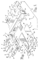
- Figures 5 and 6 show the method of manufacture of the above described fuse assembly.
- Figure 5 represents the progression by which flat metal strip stock is stamped and formed into the fuse terminal required for the fuse assembly.
- the progression shown in not intended to show every step which is taken to form the fuse terminals, but rather the figure is intended to be a diagrammatic representation of the manufacturing process.
- metal strip 102 is of sufficient width to allow for two strips of the fuse terminals to be manufactured at one time.
- the metal stock is stamped and formed as shown in steps A through G.
- the conductors 4, 6 of the fuse terminals 2 are formed by folding over the stock metal. This method of manufacture insures that the conductors will be of adequate thickness.
- the folding of conductors 4, 6 also eliminates the need to coin the fuse metal link 16, as the fuse metal link has the same thickness as the stock metal. As coining is difficult to precisely control, the use of a method which eliminates the need for coining provides for much more reliable fuses.
- two carrier strips 104 are provided which maintain the fuse terminals in a spaced relationship.
- a securing strip 106 is also provided to maintain the terminals in proper relationship. As shown at F and G of Figure 5, securing strip 106 extends between the carrier strips 104, to maintain the fuse terminals of each strip in a fixed position relative to each other.
- step H the majority of securing strip 106 is removed, thereby allowing each strip of the fuse terminals to move independently of each other.
- bar 44 is an important feature of the strip of terminals once securing strip 106 has been removed. With securing strip 106 removed from the terminals, bar 44 acts to maintain conductors 4, 6 in essentially parallel relationship. If bar 44 where not provided, fuse metal link 16 would be the only structural connection between conductors 4, 6 during steps H through K. This would be an unacceptable result, as the fuse metal link could not be able to withstand the forces associated therewith. Consequently, bar 44 prevents the failure of fuse metal link 16.
- housings 12 are provided on a carrier strip 108 to facilitate the automated production of the fuse assembly.
- carrier strip 108 has two rows of housings 12 extending therefrom. The rows of carrier strips are essentially mirror images of each other.
- a row of stamped and formed fuse terminals is provided on either side of carrier strip 108 in alignment with respective housings 12, as is illustrated in step L of Figure 6.
- the terminals are inserted into the housings, as is shown in steps L through N.
- step M once the terminal is partially inserted into the housing, a portion 46 of bar 44 is removed. As conductors 4, 6 are supported by housing 12, the structural support provided by bar 44 is not needed. The removal of portion 46 also prevents the flow of an electrical current across bar 44, thereby insuring that fuse metal link 16 will be the only portion across which an electrical current can flow between conductors 4, 6.
- the removal of portion 46 also provides fuse terminal 2 with stabilization members 42 required, as was previously discussed.
- fuse terminals 2 With fuse terminals 2 fully inserted into fuse assembly 3, the two rows of fuse assemblies are separated. Each row of fuse assemblies 3 is then placed on a real.
- the fuse assembly is relatively inexpensive to manufacture. This is due to the fact that no material is wasted, i.e. there is no need to coin the fuse metal link to the correct size.
- the terminals are manufactured from sheet metal stock which has the thickness required for the fuse metal link. In order to provide the structural advantages required by the conductors, the metal is folded over to provide the appropriate thickness. This provides for a much more accurate and stable fuse terminal because the manufacturing tolerances are easily controlled. (Coining of the fuse metal link results in inconsistent terminals due to the tolerances associated with coining.)
- bar 44 to provide the spacing required between the conductors during the manufacture of the fuse assemblies.
- the use of the bar prevents the structural failure of the fuse metal link during the manufacture of the fuse assembly.
Landscapes
- Engineering & Computer Science (AREA)
- Manufacturing & Machinery (AREA)
- Fuses (AREA)
Description
- The invention relates to a method of producing electrical fuses of the type comprising spaced-apart conductors having blade portions which extend from an insulating housing. In such a fuse a fuse metal link extends between the conductors, the fuse metal link being of identical thickness to the stock metal used to manufacture the fuses. Stabilization members are also provided to prevent the rotation and overinsertion of the fuse terminal in the housing.
- It is well known in the art to use a type of fuse for motor vehicle electrical systems which comprise spaced-apart parallel coplanar conductors that have blade portions which extend from one end of the insulating housing. The conductors have mounting portions which are supported in the insulating housing and the fuse metal link extends between these mounting portions to electrically connect the conductors.
- The specifications for universal fuses of the type described above concern only the dimensions of the fuse and its electrical characteristics. The specifications permit the manufacture of such fuses by different manufacturing methods and also permit various structural differences (as long as the required dimensions are maintained). At present, fuses available in the market are produced by stamping and forming a single piece of flat sheet metal. This produces a fuse having the fuse metal link integral with the conductors. Another type of fuse currently available has the conductors stamped and formed from strips of flat sheet metal and a conductive wire is positioned to span the gap between the conductors, providing the electrical path required between the conductors. In the alternative, fuse metal links, which are directly soldered to the conductors, are provided to electrically connect the conductors.
- Several problems are present with each of the fuses described above. Stamped and formed fuses with integral fuse metal links are costly to manufacture. As the fuse metal link is required to have conductive properties, an expensive metal (such as zinc) is required for the entire fuse. As the mounting portions are required to be thicker than fuse metal link, the fuse metal link is coined to the thickness required. Consequently, this process wastes a good amount of material, thereby increasing the cost of manufacture. The coining operation of the fuse metal link is also difficult to precisely control. Therefore, the dimensions of the fuse metal link may vary outside of tolerance limits, causing the amperage at which the fuse metal link will melt or fail to be inconsistent. This is an unacceptable result.
- Soldering conductive wires or a separate fuse metal link to the conductors also creates problems. It is extremely difficult, if not impossible, to accurately control soldering technology. Therefore, the solder joint will be inconsistent. This is an unacceptable result because the solder joint is a critical electrical connection between the conductors and the wire of the link. The inaccurate control of the solder joint may not be able to handle the rated current of the fuse. This causes the solder joint to fail before the required electrical load is encountered on the fuse metal link. Consequently, inaccurate control of the solder joint causes essentially identical fuses to have different electrical characteristics. This type of inconsistency cannot be tolerated.
- A common problem associated with the various fuses discussed relates to the handling of the fuses during the manufacture process. As only a fuse metal link or wire is to extend across the legs of the fuse, the stability of the legs is difficult to control during the manufacture process.
- The present invention concerns the production of an electrical fuse assembly which comprises a fuse terminal and an insulated housing. The fuse terminal described herein has a pair of parallel spaced-apart conductors, each of the conductors having a mounting portion and a flat blade portion. The mounting portions are mounted in the insulating housing, and the blade portions extend from one end of the insulating housing. A fuse metal link has ends connected to the mounting portions.
- Support means are provided on the conductors of the fuse terminal. The support means are provided proximate the mounting means and extend in a direction which is essentially parallel to the axis of the fuse metal link.
- Support means cooperation surfaces are provided in cavities of the housing. The surfaces are dimensioned to receive the support means thereon. This configuration allows the support means of the fuse terminal to engage the cooperation surface of the housing, thereby providing a positive alignment feature, which insures that the fuse terminal will be in proper position with respect to the housing of the fuse assembly.
- The blade portions of the electrical fuse assembly are made from metal stock which is folded over upon itself to give the blade portions an increased thickness, thereby providing the blade portions with the mechanical strength required for operation.
- Retention means are provided on the mounting portions of the fuse terminal and extend into openings provided in the housing of the fuse assembly. The retention means provided on the mounting means are formed after the fuse terminal has been inserted into the housing, thereby insuring that the fuse terminal can be inserted into the housing under minimal insertion force conditions. An electrical fuse assembly of the same general type is disclosed in DE-A-2 946 093.
- The present invention consists in a method of producing an electrical fuse assembly, as defined in claim 1.
- FR-A-2 422 250 discloses a method of producing electrical fuse assemblies, in which a strip of metal stock is progressively stamped to provide a strip of fuse terminals arranged in end to end relationship. In a repetitive operation the leading fuse terminal of the strip is severed therefrom and is inserted into an insulating housing to provide an electrical fuse assembly.
- An embodiment of the invention will now be described by way of example with reference to the accompanying drawings, in which:
- FIGURE 1 is a three dimensional view showing a fuse terminal exploded from a housing;
- FIGURE 1a is a perspective view of the fuse terminal assembled in the housing of a fuse assembly;
- FIGURE 2 is a plan view of the fuse terminal prior to being inserted into the housing of the fuse assembly;
- FIGURE 3 is a plan view of the fuse terminal inserted into the housing, a portion of the housing is shown in cross-section to more clearly show the positioning of the fuse terminal when the fuse terminal is fully inserted into the housing; and
- FIGURE 4 is a cross-sectional view, taken along line 4-4 of Figure 3, showing the fuse terminal fully inserted into the housing of the fuse assembly.
- FIGURE 5 is a diagrammatic view depicting the process which the fuse terminals are manufactured and positioned in the dielectric housing.
- FIGURE 6 is a continuation of the diagrammatic view of Figure 5 depicting the process which the fuse terminals are manufactured and positioned in the dielectric housing.
- As shown in Figure 1a, a
fuse terminal 2 offuse assembly 3, comprises a pair of spaced-apartconductors coplanar blade portions 8 which extend from abottom wall 10 of a moldeddielectric housing 12.Upper ends 13 ofconductors top wall 14 of thehousing 12 for probing purposes. -
Housing 12 can be molded from any dielectric material having the heat resistant characteristics required to withstand the heat generated by the flow of electrical current across afuse metal link 16.Housing 12 has oppositely facingsidewalls 18, oppositely facingendwalls 20,top wall 14, andbottom wall 10. Aconductor receiving cavity 22 is positioned betweensidewalls 18 andendwalls 20. Thecavity 22 extends from thetop wall 14 of thehousing 12 to thebottom wall 10. Aridge 24 is provided on the outside surfaces ofwalls 18 proximatetop wall 14. Ridge 24 allows for easy handling ofhousing 12 by either manual or automatic means. Consequently,fuse assembly 3 can be easily inserted into or removed from a mating connector (not shown). -
Fuse terminal 2 is stamped and formed from material having the structural and conductive characteristics required. As is best shown in Figures 1 and 2,fuse terminal 2 is comprised ofconductors fuse metal link 16.Conductors metal link 16 spans the distance betweenconductor -
Conductors blade portions 8, mountingportions 28, fuse metallink interconnection portions 30, andstabilization members 42. As is best shown in Figures 1 and 4,blade portions 8 are made of sheet metal stock which is folded over to give the blade portions a thickness which is essentially double the thickness of thefuse metal link 16.Blade portions 8 are of generally rectangular configuration having a firstmajor surface 32 and a secondmajor surface 34. Free ends 36 ofblade portions 8 are tapered inward to provide a lead-in surface which is beneficial asblade portions 8 are inserted into a respective mating connector (not shown). It should be noted that the thickness ofblade portions 8 provides the mechanical strength required byportions 8 to be mated and unmated without a mechanical failure ofconductors - Mounting
portions 28 extend from ends ofblade portions 8 which are opposite free ends 36. As is shown in Figures 1 and 2, the firstmajor surfaces 32 and the secondmajor surfaces 34 ofblade portions 8 are continued to mountingportions 28, thereby insuring that the width of mountingportions 28 is identical to the width ofblade portions 8.Lances 40 are provided on the mountingportions 28. As shown in Figures 1a and 3, lances 40 are formed to extend beyond firstmajor surface 32. Whenconductors housing 12, mountingportions 28 are positioned incavity 22 ofhousing 12, such that the firstmajor surface 32 and the secondmajor surface 34 are positioned proximaterespective sidewalls 18 of thehousing 12.Lances 40 of mountingportions 28 cooperate with the inside surfaces of the sidewalls 18 in order to provide a means to secure theconductors housing 12. As removal of theconductors housing 12 is attempted, thelances 40 dig into the inside surfaces ofwalls 18, thereby preventing the removal offuse terminal 2 fromhousing 12. - It should be noted that lances 40 are formed in mounting
portions 28 ofconductors fuse terminal 2 has been fully inserted intohousing 12. Consequently, fuse terminal 2 can be inserted intocavity 22 ofhousing 12 with minimal resistance, aslances 40 so not frictionally engage the sidewalls of the cavity during insertion. As is best shown in Figure 4, the forming oflances 40 is accommodated byopenings 41 provided inhousing 12.Openings 41 allow for the appropriate tooling to engage mountingportions 28 whenconductors - Overinsertion and
stabilization members 42 are provided adjacent mountingportions 28. As is best shown in Figure 2,members 42 are formed from abar 44 which extends fromconductor 4 toconductor 6. The bar is provided to maintain theconductors fuse terminals 2 are manufactured. However, prior to fuseterminals 2 being fully inserted intohousing 12, aportion 46 ofbar 44 is removed, to allow themembers 42 to cooperate withsurfaces 48 provided in thecavity 22 ofhousing 12. The removal ofportion 46 also provides a break across which the electrical current can not flow. -
Stabilization members 42 cooperate withsurfaces 48 ofhousing 12 to prevent the rotation offuse terminal 2 inhousing 12 and to prevent the overinsertion ofterminal 2 intohousing 12. As is shown in Figure 3, when terminal 12 is inserted into housing,members 42 engage withsurfaces 48. At the same time, the sides of mountingportions 28 are provided in close proximity to the surfaces ofcavity 22. This configuration prevents the rotation ofterminal 2 inhousing 12. The engagement ofmembers 42 withsurfaces 48 also provides a positive stop means forterminal 2 as the terminal in inserted into the housing. Asterminal 2 is inserted intohousing 12,members 42 will engagesurfaces 48 ofhousing 12 to prevent further insertion ofterminal 2 intohousing 12. This positive stop means insures that the terminal will be properly positioned in the housing when insertion is complete. - Fuse metal
link interconnection portions 30 extend from mountingportions 28 in the opposite direction asblade portions 8.Portions 30 have a thickness which is less than the thickness ofblade portions 8, as theportions 30 are not folded over. - Fuse
metal link 16, which is integral with the fuse metallink interconnection portions 30 ofconductors conductors terminal 2. Eachfuse metal link 16 hasinterconnection portions 56 and a bridgingportion 58.Interconnection portions 56 are provided at either end offuse metal link 16, and cooperate with theportions 30 ofconductors portion 58 extends betweeninterconnection portions 56. The dimensions of bridgingportion 58 will vary according to the amount of current which is to travel across thefuse metal link 16. The greater the width w of bridgingportion 58 offuse metal link 16, the more amperage which can be carried across the link before it fails. - Figures 5 and 6 show the method of manufacture of the above described fuse assembly. Figure 5 represents the progression by which flat metal strip stock is stamped and formed into the fuse terminal required for the fuse assembly. The progression shown in not intended to show every step which is taken to form the fuse terminals, but rather the figure is intended to be a diagrammatic representation of the manufacturing process.
- As is shown in Figure 5,
metal strip 102 is of sufficient width to allow for two strips of the fuse terminals to be manufactured at one time. The metal stock is stamped and formed as shown in steps A through G. It is important to note that theconductors fuse terminals 2 are formed by folding over the stock metal. This method of manufacture insures that the conductors will be of adequate thickness. However, the folding ofconductors fuse metal link 16, as the fuse metal link has the same thickness as the stock metal. As coining is difficult to precisely control, the use of a method which eliminates the need for coining provides for much more reliable fuses. - Through the steps described above, two
carrier strips 104 are provided which maintain the fuse terminals in a spaced relationship. A securingstrip 106 is also provided to maintain the terminals in proper relationship. As shown at F and G of Figure 5, securingstrip 106 extends between the carrier strips 104, to maintain the fuse terminals of each strip in a fixed position relative to each other. - During step H the majority of securing
strip 106 is removed, thereby allowing each strip of the fuse terminals to move independently of each other. It should be noted that the portions of securingstrip 106 which are not removedform bar 44.Bar 44 is an important feature of the strip of terminals once securingstrip 106 has been removed. With securingstrip 106 removed from the terminals, bar 44 acts to maintainconductors bar 44 where not provided, fusemetal link 16 would be the only structural connection betweenconductors fuse metal link 16. - With
metal strip 102 stamped and formed into two strips ofterminals 2, the strips of the terminals are positioned proximaterespective housings 12, as shown in Figure 6.Housings 12 are provided on acarrier strip 108 to facilitate the automated production of the fuse assembly. As is shown in Figure 6,carrier strip 108 has two rows ofhousings 12 extending therefrom. The rows of carrier strips are essentially mirror images of each other. - A row of stamped and formed fuse terminals is provided on either side of
carrier strip 108 in alignment withrespective housings 12, as is illustrated in step L of Figure 6. The terminals are inserted into the housings, as is shown in steps L through N. Referring to step M, once the terminal is partially inserted into the housing, aportion 46 ofbar 44 is removed. Asconductors housing 12, the structural support provided bybar 44 is not needed. The removal ofportion 46 also prevents the flow of an electrical current acrossbar 44, thereby insuring thatfuse metal link 16 will be the only portion across which an electrical current can flow betweenconductors portion 46 also providesfuse terminal 2 withstabilization members 42 required, as was previously discussed. - With
fuse terminals 2 fully inserted intofuse assembly 3, the two rows of fuse assemblies are separated. Each row offuse assemblies 3 is then placed on a real. - The fuse assembly is relatively inexpensive to manufacture. This is due to the fact that no material is wasted, i.e. there is no need to coin the fuse metal link to the correct size. The terminals are manufactured from sheet metal stock which has the thickness required for the fuse metal link. In order to provide the structural advantages required by the conductors, the metal is folded over to provide the appropriate thickness. This provides for a much more accurate and stable fuse terminal because the manufacturing tolerances are easily controlled. (Coining of the fuse metal link results in inconsistent terminals due to the tolerances associated with coining.)
- The use of
bar 44 to provide the spacing required between the conductors during the manufacture of the fuse assemblies. The use of the bar prevents the structural failure of the fuse metal link during the manufacture of the fuse assembly.
Claims (4)
- A method of producing an electrical fuse assembly (3), comprising the steps of:a stamping openings in a strip of sheet metal (102) having the electrical characteristics required;b forming the metal strip (102) to produce conductors (4,6), such that the conductors (4,6) have the structural strength required;c removing a support strip (106) from between respective conductors (4,6) such that positioning bars (44) are provided to structurally connect the conductors (4,6) together, the positioning bars (44) providing the spacing and positioning means to keep the respective conductors (4,6) properly positioned with respect to each other; andd removing a portion (46) of the positioning bar (44), such that the positioning bar (44) does not make electrical or structural contact between respective conductors (4,6), thereby providing a stop means proximate the positioning bar (44);e partially inserting the conductors (4,6) into a housing (12) of the fuse assembly (3) prior to removing the portion (46) of the positioning bar (44), thereby providing the conductors (4,6) with the structural support required; andf fully inserting the conductors (4,6) into the housing (12) of the fuse assembly (3) after the portion (46) of the positioning bar (44) has been removed.
- A method of producing an electrical fuse assembly (3) as claimed in claim 1, in which the conductors (4,6) are formed by folding the metal to produce a section of metal which has essentially twice the thickness as the strip of metal (102).
- A method of producing an electrical fuse assembly (3) as claimed in claim 1 or 2, comprising a strip of metal which has a width which is approximate to twice the length of a respective conductor (4,6) thereby enabling the conductors (4,6) to be produced in two simultaneous rows.
- A method of producing an electrical fuse assembly as claimed in claim 1, 2 or 3, wherein in step b said conductors (4,6) are produced in two opposite rows, steps c and d being carried out in respect of the conductors (4,6) of both of the rows, and wherein in step e two opposed rows of housings (12) are provided, each housing (12) being aligned with a respective pair of the conductors (4,6), each pair of conductors (4,6) being partially inserted into a respective housing (12) and step f then being carried out in respect of each pair of conductors (4,6) and the respective housing (12).
Applications Claiming Priority (4)
| Application Number | Priority Date | Filing Date | Title |
|---|---|---|---|
| GB888818904A GB8818904D0 (en) | 1988-08-09 | 1988-08-09 | Method of manufacturing fuse assembly |
| GB8818905 | 1988-08-09 | ||
| GB888818905A GB8818905D0 (en) | 1988-08-09 | 1988-08-09 | Fuse assembly |
| GB8818904 | 1988-08-09 |
Publications (2)
| Publication Number | Publication Date |
|---|---|
| EP0354676A1 EP0354676A1 (en) | 1990-02-14 |
| EP0354676B1 true EP0354676B1 (en) | 1993-11-24 |
Family
ID=26294257
Family Applications (1)
| Application Number | Title | Priority Date | Filing Date |
|---|---|---|---|
| EP89307369A Expired - Lifetime EP0354676B1 (en) | 1988-08-09 | 1989-07-20 | Method of manufacture of a fuse assembly |
Country Status (5)
| Country | Link |
|---|---|
| US (1) | US4998086A (en) |
| EP (1) | EP0354676B1 (en) |
| JP (1) | JP2615214B2 (en) |
| CA (1) | CA1320523C (en) |
| DE (1) | DE68910900T2 (en) |
Families Citing this family (31)
| Publication number | Priority date | Publication date | Assignee | Title |
|---|---|---|---|---|
| AR246379A1 (en) * | 1991-10-09 | 1994-07-29 | Amp Inc | Electric fuse for blade. |
| US5307562A (en) * | 1992-11-06 | 1994-05-03 | The Whitaker Corporation | Method for making contact |
| DE9411394U1 (en) * | 1994-07-14 | 1994-09-22 | Wilhelm Pudenz GmbH, 27243 Dünsen | Fuse link and fuse holder therefor |
| JPH08125352A (en) * | 1994-10-12 | 1996-05-17 | Whitaker Corp:The | Housing assembly and electric device using the same |
| US6642834B1 (en) * | 1999-03-04 | 2003-11-04 | Littelfuse, Inc. | High voltage automotive use |
| JP3815709B2 (en) * | 2000-03-31 | 2006-08-30 | 矢崎総業株式会社 | fuse |
| JP2001291464A (en) * | 2000-04-06 | 2001-10-19 | Yazaki Corp | fuse |
| JP4104817B2 (en) * | 2000-11-22 | 2008-06-18 | 太平洋精工株式会社 | Blade type fuse |
| US6878004B2 (en) * | 2002-03-04 | 2005-04-12 | Littelfuse, Inc. | Multi-element fuse array |
| US7233474B2 (en) * | 2003-11-26 | 2007-06-19 | Littelfuse, Inc. | Vehicle electrical protection device and system employing same |
| DE10358444A1 (en) * | 2003-12-13 | 2005-07-07 | Wilhelm Pudenz Gmbh | One-piece fuse-link, method for producing the one-piece fuse-link and device for carrying out the method |
| DE20319350U1 (en) | 2003-12-13 | 2004-03-04 | Wilhelm Pudenz Gmbh | Fuse insert with flat insulating body |
| CN1957434B (en) | 2004-03-05 | 2010-05-12 | 力特保险丝有限公司 | Blade type fuse for automobile |
| JP2005353465A (en) * | 2004-06-11 | 2005-12-22 | Sumitomo Wiring Syst Ltd | Fusible link mounting structure of electric connection box |
| EP1797576A4 (en) * | 2004-09-15 | 2008-12-10 | Littelfuse Inc | High voltage/high current fuse |
| US20070236322A1 (en) * | 2006-04-10 | 2007-10-11 | Jerry Edwards | Fuse having connectable terminals |
| USD559203S1 (en) | 2006-11-14 | 2008-01-08 | Littelfuse, Inc. | Indicator for a fuse |
| US7983024B2 (en) | 2007-04-24 | 2011-07-19 | Littelfuse, Inc. | Fuse card system for automotive circuit protection |
| DE102008025917A1 (en) * | 2007-06-04 | 2009-01-08 | Littelfuse, Inc., Des Plaines | High voltage fuse |
| US8674803B2 (en) * | 2007-08-13 | 2014-03-18 | Littelfuse, Inc. | Moderately hazardous environment fuse |
| US7808362B2 (en) * | 2007-08-13 | 2010-10-05 | Littlefuse, Inc. | Moderately hazardous environment fuse |
| USD575745S1 (en) | 2008-01-14 | 2008-08-26 | Littelfuse, Inc. | Blade fuse and fuse element therefore |
| US8077007B2 (en) * | 2008-01-14 | 2011-12-13 | Littlelfuse, Inc. | Blade fuse |
| USD575746S1 (en) | 2008-01-14 | 2008-08-26 | Littelfuse, Inc. | Blade fuse and fuse element therefore |
| JP5207533B2 (en) * | 2008-09-05 | 2013-06-12 | 矢崎総業株式会社 | Composite fusible link, fuse box and manufacturing method thereof |
| USD671080S1 (en) * | 2011-04-07 | 2012-11-20 | Pacific Engineering Corp. | Fuse |
| USD671504S1 (en) * | 2011-04-07 | 2012-11-27 | Pacific Engineering Corp. | Fuse |
| US9989579B2 (en) * | 2016-06-20 | 2018-06-05 | Eaton Intelligent Power Limited | Monitoring systems and methods for detecting thermal-mechanical strain fatigue in an electrical fuse |
| US11143718B2 (en) | 2018-05-31 | 2021-10-12 | Eaton Intelligent Power Limited | Monitoring systems and methods for estimating thermal-mechanical fatigue in an electrical fuse |
| US11289298B2 (en) | 2018-05-31 | 2022-03-29 | Eaton Intelligent Power Limited | Monitoring systems and methods for estimating thermal-mechanical fatigue in an electrical fuse |
| CN119626852B (en) * | 2025-02-12 | 2025-06-10 | 温州万华塑胶有限公司 | Plastic case circuit breaker base copper part assembly machine and assembly process thereof |
Family Cites Families (11)
| Publication number | Priority date | Publication date | Assignee | Title |
|---|---|---|---|---|
| US3909767A (en) * | 1974-01-14 | 1975-09-30 | Littelfuse Inc | Miniature plug-in fuse |
| DE2511459A1 (en) * | 1975-03-15 | 1976-09-23 | Rau Swf Autozubehoer | Plastic fuse box for vehicle - has plastic encapsulated fuse strips with press-fit electric connectors |
| US4224592A (en) * | 1978-04-03 | 1980-09-23 | Mcgraw-Edison Company | Miniature plug-in fuse assembly and method of manufacture |
| DE2940607A1 (en) * | 1979-10-06 | 1981-04-16 | Wilhelm Pudenz KG, 2831 Dünsen | Plug-in fuse unit - has bent H-shaped conductor, with crosspiece as melting point and verticals as flat contacts |
| DE2946093A1 (en) * | 1979-11-15 | 1981-05-27 | Wilhelm Pudenz KG, 2831 Dünsen | H-shaped conductor for thermal fuse - has cross-piece for melting and side arms acting as external contacts |
| US4344060A (en) * | 1980-09-19 | 1982-08-10 | Littelfuse, Inc. | Enclosed plug-in fuse assembly |
| FR2491255B1 (en) * | 1980-09-30 | 1985-07-05 | Dav Ind | FUSE |
| CH656979A5 (en) * | 1981-12-02 | 1986-07-31 | Pudenz Kg Wilhelm | Plug-in fuse and a method for its production |
| JPS58106732A (en) * | 1981-12-18 | 1983-06-25 | ヴイルヘルム・プ−デンツ・コマンデイ−トゲゼルシヤフト | Plug-in type fuse |
| US4394638A (en) * | 1982-07-21 | 1983-07-19 | Essex Group, Inc. | Miniature plug-in fuse assembly and method of making a fuse element therefor |
| US4672352A (en) * | 1986-04-23 | 1987-06-09 | Kabushiki Kaisha T An T | Fuse assembly |
-
1989
- 1989-06-20 US US07/368,737 patent/US4998086A/en not_active Expired - Fee Related
- 1989-07-20 EP EP89307369A patent/EP0354676B1/en not_active Expired - Lifetime
- 1989-07-20 DE DE68910900T patent/DE68910900T2/en not_active Expired - Fee Related
- 1989-07-21 CA CA000606388A patent/CA1320523C/en not_active Expired - Fee Related
- 1989-08-09 JP JP1206583A patent/JP2615214B2/en not_active Expired - Lifetime
Also Published As
| Publication number | Publication date |
|---|---|
| JP2615214B2 (en) | 1997-05-28 |
| US4998086A (en) | 1991-03-05 |
| CA1320523C (en) | 1993-07-20 |
| DE68910900D1 (en) | 1994-01-05 |
| JPH0287437A (en) | 1990-03-28 |
| DE68910900T2 (en) | 1994-06-01 |
| EP0354676A1 (en) | 1990-02-14 |
Similar Documents
| Publication | Publication Date | Title |
|---|---|---|
| CA1320523C (en) | Fuse assembly and method of manufacture | |
| EP0337659B1 (en) | Solder post retention means | |
| US4255009A (en) | Two row electrical connector | |
| US5274918A (en) | Method for producing contact shorting bar insert for modular jack assembly | |
| EP0438120B1 (en) | Branch junction box and busbars for branch connection | |
| EP0236490B1 (en) | Pin grid array electrical connector | |
| US4349804A (en) | Fuse assembly for a miniature plug-in fuse | |
| EP0503578B1 (en) | Shunted electrical connector | |
| EP0653809B1 (en) | Electrical connector and terminal therefor for mating with a blade contact | |
| EP0472006A1 (en) | Electrical terminal with means to insure that a positive electrical connection is effected | |
| US5100342A (en) | High density flat cable connector | |
| JPH0154824B2 (en) | ||
| US5061196A (en) | Selective shorting of plug pins/socket contacts in an electrical connector | |
| EP0014037B1 (en) | Electrical connector for flat cable | |
| US4527857A (en) | Terminal for connecting a wire to a blade type terminal | |
| EP0795930B1 (en) | High contact force pin-receiving electrical contact | |
| EP0185471A2 (en) | Insulation-Displacement terminal | |
| EP0191539B1 (en) | Electrical connecting terminal for a connector | |
| US5061209A (en) | Wall plate jack and contact therefor | |
| EP0390449B1 (en) | Electrical connector | |
| EP0324119A2 (en) | Stacking connector | |
| EP0355432B1 (en) | Contact assembly | |
| EP0549158B1 (en) | Insulation displacement contact having backup spring | |
| EP0004780B1 (en) | Electrical connector | |
| EP0762559A2 (en) | Electric connector terminal having a round soldering tail |
Legal Events
| Date | Code | Title | Description |
|---|---|---|---|
| PUAI | Public reference made under article 153(3) epc to a published international application that has entered the european phase |
Free format text: ORIGINAL CODE: 0009012 |
|
| AK | Designated contracting states |
Kind code of ref document: A1 Designated state(s): DE FR GB IT |
|
| 17P | Request for examination filed |
Effective date: 19900627 |
|
| 17Q | First examination report despatched |
Effective date: 19920730 |
|
| RAP1 | Party data changed (applicant data changed or rights of an application transferred) |
Owner name: THE WHITAKER CORPORATION |
|
| GRAA | (expected) grant |
Free format text: ORIGINAL CODE: 0009210 |
|
| AK | Designated contracting states |
Kind code of ref document: B1 Designated state(s): DE FR GB IT |
|
| REF | Corresponds to: |
Ref document number: 68910900 Country of ref document: DE Date of ref document: 19940105 |
|
| ET | Fr: translation filed | ||
| ITF | It: translation for a ep patent filed | ||
| PLBE | No opposition filed within time limit |
Free format text: ORIGINAL CODE: 0009261 |
|
| STAA | Information on the status of an ep patent application or granted ep patent |
Free format text: STATUS: NO OPPOSITION FILED WITHIN TIME LIMIT |
|
| 26N | No opposition filed | ||
| PGFP | Annual fee paid to national office [announced via postgrant information from national office to epo] |
Ref country code: GB Payment date: 19980623 Year of fee payment: 10 |
|
| PGFP | Annual fee paid to national office [announced via postgrant information from national office to epo] |
Ref country code: FR Payment date: 19980707 Year of fee payment: 10 |
|
| PG25 | Lapsed in a contracting state [announced via postgrant information from national office to epo] |
Ref country code: GB Free format text: LAPSE BECAUSE OF NON-PAYMENT OF DUE FEES Effective date: 19990720 |
|
| PG25 | Lapsed in a contracting state [announced via postgrant information from national office to epo] |
Ref country code: FR Free format text: THE PATENT HAS BEEN ANNULLED BY A DECISION OF A NATIONAL AUTHORITY Effective date: 19990731 |
|
| GBPC | Gb: european patent ceased through non-payment of renewal fee |
Effective date: 19990720 |
|
| REG | Reference to a national code |
Ref country code: FR Ref legal event code: ST |
|
| PGFP | Annual fee paid to national office [announced via postgrant information from national office to epo] |
Ref country code: DE Payment date: 20020731 Year of fee payment: 14 |
|
| PG25 | Lapsed in a contracting state [announced via postgrant information from national office to epo] |
Ref country code: DE Free format text: LAPSE BECAUSE OF NON-PAYMENT OF DUE FEES Effective date: 20040203 |
|
| PG25 | Lapsed in a contracting state [announced via postgrant information from national office to epo] |
Ref country code: IT Free format text: LAPSE BECAUSE OF NON-PAYMENT OF DUE FEES;WARNING: LAPSES OF ITALIAN PATENTS WITH EFFECTIVE DATE BEFORE 2007 MAY HAVE OCCURRED AT ANY TIME BEFORE 2007. THE CORRECT EFFECTIVE DATE MAY BE DIFFERENT FROM THE ONE RECORDED. Effective date: 20050720 |