EP0354559B1 - Industrial robot for pressing system, pressing system, and method for bending plate material - Google Patents
Industrial robot for pressing system, pressing system, and method for bending plate material Download PDFInfo
- Publication number
- EP0354559B1 EP0354559B1 EP89114743A EP89114743A EP0354559B1 EP 0354559 B1 EP0354559 B1 EP 0354559B1 EP 89114743 A EP89114743 A EP 89114743A EP 89114743 A EP89114743 A EP 89114743A EP 0354559 B1 EP0354559 B1 EP 0354559B1
- Authority
- EP
- European Patent Office
- Prior art keywords
- arm
- press brake
- base
- holding member
- industrial robot
- Prior art date
- Legal status (The legal status is an assumption and is not a legal conclusion. Google has not performed a legal analysis and makes no representation as to the accuracy of the status listed.)
- Expired - Lifetime
Links
Images






Classifications
-
- B—PERFORMING OPERATIONS; TRANSPORTING
- B21—MECHANICAL METAL-WORKING WITHOUT ESSENTIALLY REMOVING MATERIAL; PUNCHING METAL
- B21D—WORKING OR PROCESSING OF SHEET METAL OR METAL TUBES, RODS OR PROFILES WITHOUT ESSENTIALLY REMOVING MATERIAL; PUNCHING METAL
- B21D43/00—Feeding, positioning or storing devices combined with, or arranged in, or specially adapted for use in connection with, apparatus for working or processing sheet metal, metal tubes or metal profiles; Associations therewith of cutting devices
- B21D43/02—Advancing work in relation to the stroke of the die or tool
- B21D43/04—Advancing work in relation to the stroke of the die or tool by means in mechanical engagement with the work
- B21D43/10—Advancing work in relation to the stroke of the die or tool by means in mechanical engagement with the work by grippers
- B21D43/105—Manipulators, i.e. mechanical arms carrying a gripper element having several degrees of freedom
-
- B—PERFORMING OPERATIONS; TRANSPORTING
- B21—MECHANICAL METAL-WORKING WITHOUT ESSENTIALLY REMOVING MATERIAL; PUNCHING METAL
- B21D—WORKING OR PROCESSING OF SHEET METAL OR METAL TUBES, RODS OR PROFILES WITHOUT ESSENTIALLY REMOVING MATERIAL; PUNCHING METAL
- B21D5/00—Bending sheet metal along straight lines, e.g. to form simple curves
- B21D5/02—Bending sheet metal along straight lines, e.g. to form simple curves on press brakes without making use of clamping means
- B21D5/0281—Workpiece supporting devices
-
- B—PERFORMING OPERATIONS; TRANSPORTING
- B25—HAND TOOLS; PORTABLE POWER-DRIVEN TOOLS; MANIPULATORS
- B25J—MANIPULATORS; CHAMBERS PROVIDED WITH MANIPULATION DEVICES
- B25J15/00—Gripping heads and other end effectors
- B25J15/06—Gripping heads and other end effectors with vacuum or magnetic holding means
- B25J15/0616—Gripping heads and other end effectors with vacuum or magnetic holding means with vacuum
-
- B—PERFORMING OPERATIONS; TRANSPORTING
- B25—HAND TOOLS; PORTABLE POWER-DRIVEN TOOLS; MANIPULATORS
- B25J—MANIPULATORS; CHAMBERS PROVIDED WITH MANIPULATION DEVICES
- B25J9/00—Program-controlled manipulators
- B25J9/02—Program-controlled manipulators characterised by movement of the arms, e.g. cartesian coordinate type
- B25J9/04—Program-controlled manipulators characterised by movement of the arms, e.g. cartesian coordinate type by rotating at least one arm, excluding the head movement itself, e.g. cylindrical coordinate type or polar coordinate type
- B25J9/041—Cylindrical coordinate type
- B25J9/042—Cylindrical coordinate type comprising an articulated arm
Definitions
- the present invention relates to an industrial robot according to the preamble of claim 1 and a method for pressing plate shaped material according to the preamble of claim 8.
- Press brakes are traditionally used for bending plate shaped material at a predetermined position and a predetermined angle.
- Industrial robots are also traditionally used for carrying plate shaped material in and out of the press brakes.
- an industrial robot for a pressing equipment which essentially consists of a charging hopper being movable between two extreme positions bringing the material to be worked in and out of the press brake.
- a robot being rotatable around a vertical axis and having a two-part working arm and cooperating with a rotatable table brings metal sheets to be pressed into and out of the press brake.
- the rotatable table serves as an intermediate station on which the metal sheet is laid down after having bent one of its edges and rotated before bending another edge. Transporting the metal sheet into and out of the press brake and holding it during the bending procedure is carried out by means of special clamping means being attached to the working arm of the robot.
- a charging and decharging means for presses and other machine tools which essentially consists of an arm base, a parallelogram-type system of levers being controlled by means of a disc cam mechanism, and a transporting arm comprising a holding means which bears a metal sheet into and out of a press brake.
- the industrial robot shown in Fig. 17 has a horizontal rotary axis 103 at an upper portion of a supporting base 102.
- the horizontal rotary axis 103 coincides with a longer axis 101 of an upper die of the press brake.
- a horizontal rotary axis 105 is fixed to a leading edge portion of a squarely moving arm 104 elongated at a right angle from the horizontal rotary axis 103.
- a horizontal rotary axis 107 is fixed to a leading edge portion of a squarely moving arm 106 elongated at right angle from the horizontal rotary axis 105.
- the horizontal rotary axis 107 is the half the length of the upper die.
- a vertical rotary axis 108 is fixed to a leading edge portion of the horizontal rotary axis 107.
- a holding member 109 having plural attracting heads 110 for holding the plate shaped material, is fixed to a leading edge portion of the vertical rotary axis 108.
- the holding member 109 follows the plate shaped material 112 by movement of the horizontal rotary axis 103 when the material 112 is bent by raising a lower die 111 of the press brake.
- the holding member 109 is moved to the top surface of the piled plural material 112 by moving the horizontal rotary axes 103, 105 and 107.
- the uppermost material 112 is attracted by the plural attracting heads 110 of the holding member 109.
- the attracted material 112 is contacted with the top surface of the lower die 111 by keeping the attracting state and by again moving the horizontal rotary axes 103, 105 and 107.
- the lower die 111 is raised and the upper die 113 and the raised lower die 111 nip the material 112.
- the holding member 109 keeps hold of the material 112.
- the holding member 109 follows the material 112 by controlling and rotating a single axis, namely the horizontal rotary axis 103.
- the material 112 is carried to a disposing position by lowering the lower die 111 and moving the horizontal rotary axes 103, 105 and 107.
- the material 112 is kept attracted by the attracting heads 110 of the holding member 109 not only when the material 112 is carried in and out of the press brake but also when the material 112 is being bent. As a result, it seems possible that shifting of the material 112 is avoided. The shifting is due to shifting of the attracting start timing to changing timing of these and other operations. Thus, the bending operation is achieved with higher precision.
- the industrial robot having the arrangement described earlier, is manufactured with the recognition that attracting the material 112 is needed not only when the material 112 is carried in and out of the press brake but also when the material 112 is being bent. It is also manufactured on the assumption that the holding member 109 follows the material 112 during bending by controlling and rotating only the horizontal rotary axis 103. In practice, it is almost impossible for the holding member 109 to perfectly follow the material 112 because the mass of the portion driven by the horizontal rotary axis 103 is extremely great. As a result, bending force is applied to the material 112. The bending force is generated by the imperfect following of the holding member 109 when the pressing processing speed of the press brake is not varied at all. This has the disadvantage of lowering the precision of the finished products.
- the holding member 109 perfectly follows the material 112 by lowering the pressing processing speed of the press brake.
- the press brake can control the bending angle by nipping the material 112 with the upper die 113 and the lower die 111 and controlling the degree of nipping. Accordingly, the nipping speed is generally kept at a constant speed. But the portion of the material 112 attached by the attracting heads 110 of the holding member 109 moves at the speed corresponding to the trigonometrical function value determined by the bending angle.
- the moving rate of the holding member 109 is not kept constant but is varied in correspondence with the bending angle from beginning of the bending operation to finishing of the bending operation.
- imperfect following of the holding member 109 is obtained under the ordinary pressing speed of the press brake because it is affected by the mass of the portion driven by the horizontal rotary axis 103.
- Imperfect following of the holding member 109 is also obtained because the locus of bending is not constant due to a tolerance of thickness of the material 112.
- a moving extent of the holding member 109 can not be determined because movability, resposibility, and physical strength of the industrial robot are greatly influenced when the moment of inertia and the like of arm members is increased too much based on increment of arm driving radius.
- peripheral devices for transporting plate shaped material 112 to the limit position of the holding member 109, and peripheral devices for transporting plate shaped material 112 from the limit position of the holding member 109 to the piling up position and the like are additionally required.
- the press brake is disadvantageously large-sized as a whole and complicated in its hardware construction and its interrelated control of each device and others.
- the industrial robot has no degree of freedom of the holding member 109 in a width direction of the press brake. This gives rise to the disadvantage that, when the material 112 has holes at the central portion thereof, imperfect attracting of the plate shaped material 112 results due to opposition of the attracting heads 110 to the holes in the material 112.
- the direction of carrying the material 112 in the press brake with the industrial robot is previously determined as the front side of the press brake. Additional devices for transporting the material 112 between plural press brakes are required, thereby complicating the construction of an automated line. Also, two species of industrial robots are needed in the event that the disposition of the industrial robot relative to the press brake is on the opposite side relative to the disposition of the press brake, the disposition with other peripheral devices, or the carrying in and out position of the material 112.
- the industrial robot having the arrangement described above, moves the base arm to a predetermined position and operates the plural second arm members of the working arm positioned between plural rotatable members, thereby moving the holding member following the movement and operation to hold the material.
- the material is raised to the altitude after held by the holding member.
- the base arm is moved and more than one vertical rotatable member and horizontal rotatable member of the working arm are operated if necessary to adjust the holding state of the material to suit carrying the material in the press brake.
- the material is then finally carried in the press brake.
- the material is released by stopping the holding operation of the holding member provided the material is held by the press brake.
- the material is nipped by an upper die and a lower die of the press brake.
- the holding member then nearly follows the material being bent by operating more than one vertical rotatable member and horizontal rotatable member following the pressing of the press brake. As a result, the holding member contacts the material with scarce delay when the pressing has finished.
- the material is held by the holding member while the upper die and the lower die are apart relative to one another. The material is then transported to the disposing position by moving the base arm.
- the moving extent of working arm is easily enlarged because the base arm reciprocates on the arm base and the working arm operates at a predetermined position within the reciprocating extent of the base arm by operating the vertical rotatable members and the horizontal rotatable members.
- the holding member can be arranged at any of the symmetrical sides on the base of the base arm because the working arm operates simply by moving to and fro on the base of the base arm, The material can be carried in and out despite the disposition of the industrial robot relative to the press brake.
- each second arm member constituting the working arm, is determined by the minimum length required for the operation, because the base arm moves to a limit position which is the position for carrying the material in and out of the press brake and the pressing is performed around the operation of the working arm at the limit position.
- the mass of the working arm is accordingly decreased.
- the holding member is not influenced by the moment of inertia which is too much, and the holding member is remarkably raisen its followability when a driving source is controlled.
- holding of the plate shaped material by the holding member is not necessary because the material is nipped by the upper die and the lower die, thereby simplifying the robot control during the pressing processing.
- the arm base is positioned in the region not opposite the front and the side of the press brake.
- the front is used for carrying the plate shaped material in and out of the pressing section for bending of the press brake.
- Operation control for carrying the plate shaped material in and out of the press brake is simplified because a space in front of the press brake is maintained as a large operation region, and the arm base is disposed so as not to be opposite the press brake.
- the first arm member has a length so that the leading end of the first arm member is opposite to the front center portion of the press brake.
- the second arm members, driven by the vertical rotatable members and the horizontal rotatable members, are determined by the minimum length necessary to prevent remarkable increasing of the moving speed of the base arm for maintaining the predetermined moving speed of the plate shaped material, thereby extremely decreasing the mass of the working arm so as to remarkably improve the following of the holding member when a driving source is controlled.
- control means outputs the operating command to each rotatable member of the robot arm so as to move the holding member to reach the predetermined position of the bent plate shaped material when the pressing processing for bending of the press brake is finished.
- the holding member includes a third arm member and attracting heads provided thereto, that the attracting heads attract the material by contacting the attracting heads to the material and discharging air therefrom, that the releasing means is a forcible releasing mechanism attached to the attracting heads for releasing the plate shaped material, and that the forcible releasing mechanism is driven by a releasing command from the control means.
- At least a base arm moving member of the arm base is constructed above a floor.
- the first arm member elongated in a horizontal direction of the base arm, is supported rotatably in a horizontal plane by intervening the vertical rotatable member.
- the arm base is positioned in the region not opposite either the front or the side of the press brake, that the front is used for carrying the material in and out of the pressing section of the press brake for bending, and that the first arm member has a length so its leading end is opposite to the front center portion of the press brake, that the control means outputs an operation command to each rotatable member of the robot arm to move the holding member to reach predetermined position of the bent material when the pressing for bending of the press brake is finished, that the holding member comprises a third arm member and attracting heads provided thereto, that the attracting heads attract the material by contacting the attracting heads to the material and discharging air therefrom, that the releasing means is a forcible releasing mechanism attached to the attracting heads for releasing the plate shaped material, and that the forcible
- a support base for supporting the material is provided with the press brake, that the support base includes a plural support arms and a rotary mechanism for rotating the support arms in a horizontal plane, and that the distance between the support arms is not narrower than the holding member.
- the support base is provided at position not higher than an upper die of the press brake, and that each support arm has attracting heads for fixing the material.
- the first arm member elongated in a horizontal direction of the base arm, is supported rotatably in a horizontal plane by intervening a vertical rotatable member, and that one or more press brakes are further disposed.
- a method for bending plate shaped material comprises the steps according to claim 8.
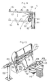
- Fig. 1 is a schematic perspective view showing an industrial robot according to the present invention and a press brake.
- an industrial robot 2 is disposed relative to a press brake 1 at a position not to be opposite to either a front face or a side face of the press brake 1.
- the press brake 1 has an upper die 11, a lower die 12, and a support base 5 for temporarily supporting in an attracting manner, a plate shaped material 3 to be carried in the press brake 1.
- the support base 5 preferably includes a manipulating handle 51, axes 52 and attracting heads 54 having an arrangement to automatically destruct the vacuum, as shown in Fig. 3.
- the manipulating handle 51 is used to adjust location of the support base 5 in the width direction of the press brake 1, and the axes 52 are used to rotate the support base 5 for selecting a restored condition positioning the support base 5 along the front face of the press brake 1.
- the attracting head 54 is also shown in Figs. 5(a) and 5(B), and includes a body 54a having an air outlet 54b, and attracting pad 54c reciprocally mounted in the body 54a, a sealing member 54d for securing contact of the attracting pad 54c to the air outlet portion of the body 54a and preventing leakage of air, a spring member 54e for forcibly contacting the attracting pad 54c to the sealing member 54d, and plungers 54f for regulating posture of the attracting pad 54c.
- the air outlet 54b runs into a vacuum generator or the like (not shown).
- a robot controller 20 is provided as a control means.
- the press brake 1 also has a back gauge (not shown) for regulating a margin for bending and for adjusting the margin based on the input value from outward.
- Fig. 2 is a perspective view of a first embodiment of an industrial robot according to the present invention.
- the industrial robot 2 has an arm base 21 having a predetermined length, a base arm 22 reciprocally movably supported to the arm base 21, a working arm W provided along the the leading edge portion of the base arm 22 opposite to the arm base side portion, and a holding member H for holding a plate shaped material 3, provided along the the leading edge portion of the working arm W.
- the base arm 22 is provided with the base side portion of a robot arm.
- the base arm 22 has a vertically standing member 22a reciprocally moved by a reciprocating axis (not shown) provided in the arm base 21, and a first arm member 22b, extending in a horizontal direction, provided with the the leading edge portion of the vertically standing member 22a.
- the first arm member 22b has a length extending from opposite its leading hedge portion to the front center portion of the press brake.
- the working arm W has three second arm members 24, 26 and 28, rotatable members 25 and 27 intervened between the second arm members, and rotatable member 23 intervened between the second arm member 24 and the first arm member 22b.
- the rotatable members 23 and 25 are horizontal rotatable members extending in a horizontal direction, while the rotatable member 27 is a vertical rotatable member extending in a vertical direction.
- the second arm member 24 extends to a direction which is rectangular to the horizontal rotatable member 23, while the second arm members 26 and 28 extend to a direction of rotatable members 25 and 27, respectively.
- the second arm member 24 is accordingly rotated in a vertical plane by the horizontal rotatable member 23, while the second arm members 26 and 28 are turned on their axes by the rotatable members 25 and 27, respectively.
- the second arm members 24, 26 and 28 have a length corresponding to the minimum length necessary to suppress remarkable increase of moving speed of the base arm 22.
- the moving speed is necessary for maintaining the predetermined moving speed of the plate shaped material 3 when the material 3 is being bent.
- the holding member H has a holding member body 29 provided with the the leading edge portion of the second arm member 28 and plural attracting heads 30 provided with the the leading edge portion of the holding member body 29.
- the robot controller 20 outputs various necessary operation commands to the industrial robot 2 and the press brake 1.
- Plural plate shaped material 3 are piled on a material support base 4 which is opposite to the front of the press brake 1 and separated from the press brake by a predetermined distance.
- the base arm 22 is moved to a position opposite the material support base 4 by the reciprocating axis (not shown), and the rotatable members 23, 25 and 27 are operated to contact plural attracting heads 30 of the holding member H with the uppermost plate shaped material 3.
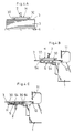
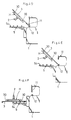
- the material 3 is then attracted by the attracting heads 30 (see Fig. 4(A)). Attracting the material 3 is performed by contacting the attracting heads 30 with the material 3 and discharging air therefrom to generate a negative pressure by a vacuum generator (not shown) or the like(see Fig. 6,) which runs into the attracting heads 30through a valve 30k or the like as a releasing means.
- the uppermost material 3 is lifted up by operating each rotatable member 23, 25 and 27 in a reverse direction.
- the material 3, thus lifted up, is carried in the press brake 1 to position the bending portion of the material 3 between the upper die 11 and the lower die 12 (see Fig. 4(B)), by moving the base arm 22 by the reciprocating axis toward the press brake 1 and operating each rotary axis, if necessary, to change the posture of the material 3.
- the material 3 is further moved to contact with the back gauge (not shown).
- the material 3 is then supported on the support base 5 by attracting the material 3 with the attracting heads 54 of the support base 5. Thereafter, the material 3 is released from the holding member H by stopping the attracting operation with the attracting heads 30.
- the accurately positioned material 3 is now attracted and supported by the support base 5 which is raised to the altitude equal to the top surface of the lower die 12.
- the holding member H is moved to the position below the material 3 and reversed to position the attracting heads 30 upward by moving the base arm 22 and operating each rotatable member, thereby allowing the movement of the material 3 following the pressing (see Fig. 4(C)).
- the material 3 may be attracted by the attracting heads 30.
- the clearance 54g is formed by slightly moving the material 3, more particularly when the material 3 is started bending by nipped with the upper die 11 and the lower die 12, the attracting pad 54c follows the material 3, while the body 54a remains as it is because the meterial 3 is attracted with the attracting head 54, resulting the movement of the attracting pad 54c against the spring member 54e to form the clearance 54g.
- the bending angle of the material is accordingly determined accurately by controlling the coming down distance of the upper die 11. Also, when the bending operation described above is carried out, the holding member H nearly follows the attracting position of the material 3, (see Fig. 4(D)) which goes up at high speed following the bending operation, by controlling the operation of the reciprocating axis and the rotatable members 23 and 25.
- the followability of the holding member H may not be so high because the attracting of the material 3 is stopped. But the holding member H highly follows the material 3 because the mass of the leading edge portion than the horizontal rotatable member 23 is small enough. Accordingly, attracting the material 3 with the attracting heads 30 is performed with scarce delay time after bending the material 3 is finished. Afterward, the material 3 is securely held by the holding member H even when the upper die 11 goes up (see Fig. 4(E)), thereby preventing the material 3 from dropping. Thereafter, the material 3 is moved to a position not shown by moving the reciprocating axis of the base arm 22 and operating each rotatable member. The material 3 is then piled by stopping the attracting operation with the attracting heads 30.
- the material 3 When the material 3 is required to be bent more than twice and in the same directions, the material 3 is charged in direction by operating each rotary axis of the working arm W, and is then carried in the press brake 1. The second bending and so on is then performed as the first bending described earlier.
- the material 3 held by the holding member H is moved to the support base 5 and supported by the support base 5 (see Fig. 4(F)).
- the attracting heads 30 then contact to the bottom of the material 3 by operating each rotatable member of the working arm W, thereby attracting the material 3 (see Fig. 4(G)).
- the top and the bottom of the material 3 is reversed by operating each rotatable member of the working arm W, and the material 3 is moved to the top surface of the lower die 12.
- the bending operation for the second time in the reverse direction is performed in the same manner as the bending operation for the first time described earlier.
- the bent material 3 is carried out of the press brake 1 and piled at the predetermined position by moving the base arm 22 and operating the working arm W.
- the bent material 3 may be uniformly piled.
- every other material 3 should be piled with its top and bottom in a reversed state through supporting the material 3 by the support base 5 and reversing the attracting surface of the material 3 by operating each rotatable member of the working arm W.
- the support base 5 is rotated around the axes 52 to the position along the front of the press brake, thereby extremely widening the space for operating the holding member H.
- a flatcar for transporting the material may be employed as a support base 4 by designing the arm base 21 to have enough length, and stopping position of the flatcar may flexibly be determined.
- the material 3 is smoothly carried in, bent, and carried out in the same manner as above, when the press brake 1 and the support base 4 are positioned at an interval which corresponds to the reciprocating distance of the base arm 22.
- Fig. 7 is a schematic perspective view of a second embodiment of an industrial robot according to the present invention.
- a base arm 32 reciprocally hangs down from an arm base 31, instead of the base arm 22 reciprocally standing on the arm base 21. Further, the base arm 32 has a vertical hanging member 32a and a first arm member 32b. Arrangement of the other part is the same as the first embodiment.
- the lower die 12 may be moved up and down instead of the upper die 11 being moved up and down.
- Fig. 8 is a perspective view of a third embodiment of an industrial robot according to the present invention.
- the base arm 22 includes a vertical standing member 22a reciprocal with the arm base 21, a first arm member 22b, extending in a horizontal direction, provided with the the leading edge portion of the vertical standing member 22a, and a vertical rotatable member 22c extending in a vertical direction intervened between the vertical standing member 22a and the first arm member 22b.
- Arrangement of the other part is the same as the first embodiment.
- degree of freedom for controlling the posture of the plate shaped material 3 is increased because the first arm member 22b can be rotated in a horizontal plane. More particularly, when the industrial robot 2 is not required in operation, the working arm W and the holding member H are positioned directly over the arm base 21 as a whole (refer to dot-chain line in Fig. 9) by rotating only the first arm member 22b, thereby making free front space of the press brake 1. As a result, operability is improved when the die is exchanged, manual operation is carried out and so on.
- the holding member H is moved in a width direction of the press brake 1 through rotating the first arm member 22b by operating the vertical rotatable member 22c, and moving the base arm 22 by operating the reciprocal moving axis corresponding to the rotation angle of the first arm member 22b (refer to two dot-dash line in Fig. 8), thereby accomplishing the secure holding of the material with the holding member H.
- Fig.10 is a plan view schematically showing a press brake system for performing pressing with two press brakes.
- Two press brakes 1 and 1a are separated by a predetermined distance in their width direction.
- the industrial robot 2, having the arrangement shown in Fig. 7, is disposed at the intermediate position of the press brakes 1 and 1a.
- a carrying material in line 6 extends to opposite the front predetermined position of the press brake 1, and a carrying material out line 7 extends to opposite the front predetermined position of the press brake 1a.
- the press brakes 1 and 1a have dies, which are different to each other.
- the material 3 is carried in the press brake 1 by the industrial robot 2.
- the material 3 sequentially supplied through the carrying material in line 6, and pressing is performed by the press brake 1.
- the pressed material 3 is carried in the press brake 1a through rotating the first arm member 22b by approximately 180 degrees by operating the vertical rotatable member 22c of the industrial robot 2 and by operating rotary axes of the working arm W. Pressing is performed by the press brake 1a.
- the material 3 thus pressed by both press brakes 1 and 1a is transported to the carrying material out line 7 by the industrial robot 2.
- the working arm W and the holding member H are positioned directly over the arm base 21 as a whole (refer to dot-chain line in Fig.10) by rotating only the vertical rotatable member 22c, thereby making free front space of the press brakes 1 and 1a.
- operability is improved when the die is exchanged, manual operation is carried out, and so on.
- another press brake is disposed opposite one of the press brakes 1 and 1a, and that the material 3 is moved between three press brakes by one industrial robot 2.
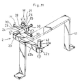
- Fig. 11 is a schematic view of a fourth embodiment of an industrial robot according to the present invention.
- a base arm 32 reciprocally hangs down from an arm base 41 instead of the base arm 22 reciprocally standing on the arm base 21.
- the base arm 42 has a vertical hanging member 42a, a first arm member 42b, and a vertical rotatable member 42c. Arrangement of the other part is the same as the first embodiment.
- this embodiment availability of the space above the floor is improved because the arm base 41 exists above the floor. Also, this embodiment performs the same operations as the third embodiment.
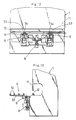
- Fig. 12 is a schematic front view of a fifth embodiment of a support base according to the present invention, while Fig. 13 is a side view of the same.
- a support base 5 is provided at the front predetermined position of the press brake 1 which has a lower die 12 fixed at the predetermined position thereof and an upper die 11 movable upward and downward.
- the support base 5 includes a pair of support arms 53 connected to the press brake 1 with an intervening elevating mechanism 8 and a rotating mechanism 9. It is prefered that the support base 5 includes more than three support arms 53.
- the elevating mechanism 8 includes: a pair of frames 81 fixed to the front face of the press brake 1, guide shafts 82 supported by the frame 81, movable frames 83 movably engaged upward and downward with the guide shaft 82, a cylinder device 84 fixed to the predetermined position of the press brake 1, and link members 85 for interconnecting a piston rod of the cylinder device 84 and each movable frame 83.
- both moving frames 83 can move upward and downward simultaneously following the operation of the cylinder device 84.
- the rotating mechanism 9 includes: rotary support members 91 for rotatably supporting the base portion of the support arms 53, driving sources 92 for supplying rotary force to the support arms 53, and rotation limiting members 93 for regulating a rotary limit of the support arms 53.
- the support arms 53 can move between two limit positions by driving the driving sources 92.
- One limit position lays the support arms 53 along the front surface of the press brake 1, while the other limit position rectangularly projects the support arms 53 from the front surface of the press brake 1.
- Both driving sources 92 are synchronized to be driven the same quantity in opposite directions to one another.
- the support arms 53 have a length for stably supporting thereon the maximum sized plate shaped material 3 to be bent, and have plural attracting heads 54 at every predetermined interval.
- the attracting heads 54 have a predetermined height to form a space between the top surface of the supporting arm 53 and the attracting surface of the attracting heads 54. This space is sufficient for housing the edge portion of the material 3 already bent.
- the support arm 53 can be lowered through rotating the link members 85 by projecting the piston rod of the cylinder device 84, and lowering both movable frames 83 along the guide shafts 82, thereby eliminating interference of the material 3 with each axis.
- the support arm 53 can be lifted through rotating the link members 85 in a reverse direction by pulling in the piston rod of the cylinder device 84, and lifting both movable frames 83 along the guide shafts 82, thereby maintaining sufficient space for holding the material 3 with the holding member H.
- the industrial robot or the pressing system as set forth is constructed such that the support base (5) is positioned no higher than an upper die (11) of said press brake (1), and said support arm (53) further has attracting heads (54) for fixing said material (3).
- the base arm (22, 42) further includes a vertical rotatable member (22c, 42c), said first arm member (22b, 42b) is rotatably supported in a horizontal plane by intervening said vertical rotatable member (22c, 42c), and one or more press brakes (1) are further disposed.
Landscapes
- Engineering & Computer Science (AREA)
- Mechanical Engineering (AREA)
- Robotics (AREA)
- Bending Of Plates, Rods, And Pipes (AREA)
Description
- The present invention relates to an industrial robot according to the preamble of
claim 1 and a method for pressing plate shaped material according to the preamble ofclaim 8. - Press brakes are traditionally used for bending plate shaped material at a predetermined position and a predetermined angle. Industrial robots are also traditionally used for carrying plate shaped material in and out of the press brakes.
- For example, from EP-A-0 125 189 an industrial robot for a pressing equipment is known which essentially consists of a charging hopper being movable between two extreme positions bringing the material to be worked in and out of the press brake.
- From FR-A-25 84 634 another method and device for the handling of metal sheets, especially to be incorporated into a pressing equipment, is known. Herein a robot being rotatable around a vertical axis and having a two-part working arm and cooperating with a rotatable table brings metal sheets to be pressed into and out of the press brake. The rotatable table serves as an intermediate station on which the metal sheet is laid down after having bent one of its edges and rotated before bending another edge. Transporting the metal sheet into and out of the press brake and holding it during the bending procedure is carried out by means of special clamping means being attached to the working arm of the robot.
- From FR-A-24 40 233 forming the base for the preamble of the claims a charging and decharging means for presses and other machine tools is known which essentially consists of an arm base, a parallelogram-type system of levers being controlled by means of a disc cam mechanism, and a transporting arm comprising a holding means which bears a metal sheet into and out of a press brake.
- From Japanese patent laying open gazette No. Sho 59-175968 an industrial robot is known which will be described in the following.
- The industrial robot shown in Fig. 17 has a horizontal
rotary axis 103 at an upper portion of a supportingbase 102. The horizontalrotary axis 103 coincides with alonger axis 101 of an upper die of the press brake. A horizontalrotary axis 105 is fixed to a leading edge portion of a squarely movingarm 104 elongated at a right angle from the horizontalrotary axis 103. A horizontalrotary axis 107 is fixed to a leading edge portion of a squarely movingarm 106 elongated at right angle from the horizontalrotary axis 105. The horizontalrotary axis 107 is the half the length of the upper die. A verticalrotary axis 108 is fixed to a leading edge portion of the horizontalrotary axis 107. Aholding member 109, having plural attractingheads 110 for holding the plate shaped material, is fixed to a leading edge portion of the verticalrotary axis 108. Theholding member 109 follows the plate shapedmaterial 112 by movement of the horizontalrotary axis 103 when thematerial 112 is bent by raising alower die 111 of the press brake. - In the press brake system described earlier, the
holding member 109 is moved to the top surface of the piledplural material 112 by moving the horizontalrotary axes uppermost material 112 is attracted by theplural attracting heads 110 of theholding member 109. Then, the attractedmaterial 112 is contacted with the top surface of thelower die 111 by keeping the attracting state and by again moving the horizontalrotary axes lower die 111 is raised and theupper die 113 and the raised lower die 111 nip thematerial 112. When thematerial 112 is bent in the manner described above, theholding member 109 keeps hold of thematerial 112. Following the bending operation, theholding member 109 follows thematerial 112 by controlling and rotating a single axis, namely the horizontalrotary axis 103. After the bending operation is finished, thematerial 112 is carried to a disposing position by lowering thelower die 111 and moving thehorizontal rotary axes - As is apparent from the foregoing, the
material 112 is kept attracted by theattracting heads 110 of theholding member 109 not only when thematerial 112 is carried in and out of the press brake but also when thematerial 112 is being bent. As a result, it seems possible that shifting of thematerial 112 is avoided. The shifting is due to shifting of the attracting start timing to changing timing of these and other operations. Thus, the bending operation is achieved with higher precision. - The industrial robot, having the arrangement described earlier, is manufactured with the recognition that attracting the
material 112 is needed not only when thematerial 112 is carried in and out of the press brake but also when thematerial 112 is being bent. It is also manufactured on the assumption that theholding member 109 follows thematerial 112 during bending by controlling and rotating only the horizontalrotary axis 103. In practice, it is almost impossible for theholding member 109 to perfectly follow thematerial 112 because the mass of the portion driven by the horizontalrotary axis 103 is extremely great. As a result, bending force is applied to thematerial 112. The bending force is generated by the imperfect following of theholding member 109 when the pressing processing speed of the press brake is not varied at all. This has the disadvantage of lowering the precision of the finished products. On the contrary, theholding member 109 perfectly follows thematerial 112 by lowering the pressing processing speed of the press brake. This inevitably gives rise to the disadvantage that the processing processing speed of the press brake is lowered by employing the industrial robot. More particularly, the press brake can control the bending angle by nipping thematerial 112 with theupper die 113 and thelower die 111 and controlling the degree of nipping. Accordingly, the nipping speed is generally kept at a constant speed. But the portion of thematerial 112 attached by theattracting heads 110 of theholding member 109 moves at the speed corresponding to the trigonometrical function value determined by the bending angle. The moving rate of theholding member 109 is not kept constant but is varied in correspondence with the bending angle from beginning of the bending operation to finishing of the bending operation. As a result, imperfect following of theholding member 109 is obtained under the ordinary pressing speed of the press brake because it is affected by the mass of the portion driven by the horizontalrotary axis 103. Imperfect following of theholding member 109 is also obtained because the locus of bending is not constant due to a tolerance of thickness of thematerial 112. - Further, a moving extent of the
holding member 109 can not be determined because movability, resposibility, and physical strength of the industrial robot are greatly influenced when the moment of inertia and the like of arm members is increased too much based on increment of arm driving radius. Thus, peripheral devices for transporting plate shapedmaterial 112 to the limit position of theholding member 109, and peripheral devices for transporting plate shapedmaterial 112 from the limit position of theholding member 109 to the piling up position and the like are additionally required. The press brake is disadvantageously large-sized as a whole and complicated in its hardware construction and its interrelated control of each device and others. - Furthermore, as apparent from Fig. 16, the industrial robot has no degree of freedom of the
holding member 109 in a width direction of the press brake. This gives rise to the disadvantage that, when thematerial 112 has holes at the central portion thereof, imperfect attracting of the plate shapedmaterial 112 results due to opposition of the attractingheads 110 to the holes in thematerial 112. - Further, the direction of carrying the
material 112 in the press brake with the industrial robot is previously determined as the front side of the press brake. Additional devices for transporting thematerial 112 between plural press brakes are required, thereby complicating the construction of an automated line. Also, two species of industrial robots are needed in the event that the disposition of the industrial robot relative to the press brake is on the opposite side relative to the disposition of the press brake, the disposition with other peripheral devices, or the carrying in and out position of thematerial 112. - It is an object of the present invention to simplify a construction of a press brake system as a whole.
- It is another object of the present invention to give degree of freedom to an industrial robot in a direction which is rectangular to a direction for carrying in of a press brake.
- It is a further object of the present invention to enlarge a moving extent of an industrial robot.
- It is a still further object of the present invention to increase a flexibility of the industrial robot.
- To perform the objects mentioned above, an industrial robot in accordance with
claim 1 is provided - The industrial robot, having the arrangement described above, moves the base arm to a predetermined position and operates the plural second arm members of the working arm positioned between plural rotatable members, thereby moving the holding member following the movement and operation to hold the material. The material is raised to the altitude after held by the holding member. Thereafter, the base arm is moved and more than one vertical rotatable member and horizontal rotatable member of the working arm are operated if necessary to adjust the holding state of the material to suit carrying the material in the press brake. The material is then finally carried in the press brake. Thereafter, the material is released by stopping the holding operation of the holding member provided the material is held by the press brake. For example, the material is nipped by an upper die and a lower die of the press brake. The holding member then nearly follows the material being bent by operating more than one vertical rotatable member and horizontal rotatable member following the pressing of the press brake. As a result, the holding member contacts the material with scarce delay when the pressing has finished. The material is held by the holding member while the upper die and the lower die are apart relative to one another. The material is then transported to the disposing position by moving the base arm.
- Summarizing the above, the moving extent of working arm is easily enlarged because the base arm reciprocates on the arm base and the working arm operates at a predetermined position within the reciprocating extent of the base arm by operating the vertical rotatable members and the horizontal rotatable members. The holding member can be arranged at any of the symmetrical sides on the base of the base arm because the working arm operates simply by moving to and fro on the base of the base arm, The material can be carried in and out despite the disposition of the industrial robot relative to the press brake. Further, each second arm member, constituting the working arm, is determined by the minimum length required for the operation, because the base arm moves to a limit position which is the position for carrying the material in and out of the press brake and the pressing is performed around the operation of the working arm at the limit position. The mass of the working arm is accordingly decreased. Hence, the holding member is not influenced by the moment of inertia which is too much, and the holding member is remarkably raisen its followability when a driving source is controlled. On the other hand, holding of the plate shaped material by the holding member is not necessary because the material is nipped by the upper die and the lower die, thereby simplifying the robot control during the pressing processing.
- The arm base is positioned in the region not opposite the front and the side of the press brake. The front is used for carrying the plate shaped material in and out of the pressing section for bending of the press brake. Operation control for carrying the plate shaped material in and out of the press brake is simplified because a space in front of the press brake is maintained as a large operation region, and the arm base is disposed so as not to be opposite the press brake.
- It is also preferable that the first arm member has a length so that the leading end of the first arm member is opposite to the front center portion of the press brake. In this case, the second arm members, driven by the vertical rotatable members and the horizontal rotatable members, are determined by the minimum length necessary to prevent remarkable increasing of the moving speed of the base arm for maintaining the predetermined moving speed of the plate shaped material, thereby extremely decreasing the mass of the working arm so as to remarkably improve the following of the holding member when a driving source is controlled.
- It is preferable that the control means outputs the operating command to each rotatable member of the robot arm so as to move the holding member to reach the predetermined position of the bent plate shaped material when the pressing processing for bending of the press brake is finished.
- It is further preferable that the holding member includes a third arm member and attracting heads provided thereto, that the attracting heads attract the material by contacting the attracting heads to the material and discharging air therefrom, that the releasing means is a forcible releasing mechanism attached to the attracting heads for releasing the plate shaped material, and that the forcible releasing mechanism is driven by a releasing command from the control means.
- It is further preferable that at least a base arm moving member of the arm base is constructed above a floor.
- It is still further preferable that the first arm member, elongated in a horizontal direction of the base arm, is supported rotatably in a horizontal plane by intervening the vertical rotatable member. In this case, it is preferable that the arm base is positioned in the region not opposite either the front or the side of the press brake, that the front is used for carrying the material in and out of the pressing section of the press brake for bending, and that the first arm member has a length so its leading end is opposite to the front center portion of the press brake, that the control means outputs an operation command to each rotatable member of the robot arm to move the holding member to reach predetermined position of the bent material when the pressing for bending of the press brake is finished, that the holding member comprises a third arm member and attracting heads provided thereto, that the attracting heads attract the material by contacting the attracting heads to the material and discharging air therefrom, that the releasing means is a forcible releasing mechanism attached to the attracting heads for releasing the plate shaped material, and that the forcible releasing mechanism is driven by a releasing command from the control means.
- It is preferable that a support base for supporting the material is provided with the press brake, that the support base includes a plural support arms and a rotary mechanism for rotating the support arms in a horizontal plane, and that the distance between the support arms is not narrower than the holding member. In this case, it is further preferable that the support base is provided at position not higher than an upper die of the press brake, and that each support arm has attracting heads for fixing the material.
- It is also preferable that the first arm member, elongated in a horizontal direction of the base arm, is supported rotatably in a horizontal plane by intervening a vertical rotatable member, and that one or more press brakes are further disposed.
- To perform the objects mentioned above, a method for bending plate shaped material comprises the steps according to
claim 8. - The steps according to claims 9-12 are preferably included.
-
- Figure 1 is a schematic perspective view showing a press brake system incorporating an industrial robot according to a first embodiment of the present invention;
- Figure 2 is a perspective view showing a first embodiment of an industrial robot according to the present invention;
- Figure 3 is a schematic perspective view showing a support base of a press brake;
- Figures 4(A) to 4(G) are schematic side views explaining a bending operation for a plate shaped material;
- Figures 5(A) and 5(B) are schematic vertical section views showing an attracting head of a support base;
- Figure 6 is a schematic perspective view showing an attracting head of a holding member;
- Figure 7 is a schematic perspective view showing a second embodiment of an industrial robot according to the present invention;
- Figure 8 is a perspective view showing a third embodiment of an industrial robot according to the present invention;
- Figure 9 is a diagram useful in understanding degree of freedom of an industrial robot in a width direction of a press brake;
- Figure 10 is a plan view schematically showing a press brake system for performing pressing with two press brake;
- Figure 11 is a schematic perspective view showing a fourth embodiment of an industrial robot according to the present invention;
- Figure 12 is a schematic front view showing a support base provided with a press brake;
- Figure 13 is a side view of the same;
- Figure 14 is an enlarged front view showing a support base;
- Figure 15 is an enlarged plan view of the same;
- Figure 16 is an enlarged side view of the same; and
- Figure 17 is a schematic perspective view showing a conventional press brake system incorporating an industrial robot.
- Fig. 1 is a schematic perspective view showing an industrial robot according to the present invention and a press brake.
- In Fig. 1, an
industrial robot 2 is disposed relative to apress brake 1 at a position not to be opposite to either a front face or a side face of thepress brake 1. Thepress brake 1 has anupper die 11, alower die 12, and asupport base 5 for temporarily supporting in an attracting manner, a plate shapedmaterial 3 to be carried in thepress brake 1. Thesupport base 5 preferably includes a manipulatinghandle 51, axes 52 and attractingheads 54 having an arrangement to automatically destruct the vacuum, as shown in Fig. 3. The manipulatinghandle 51 is used to adjust location of thesupport base 5 in the width direction of thepress brake 1, and theaxes 52 are used to rotate thesupport base 5 for selecting a restored condition positioning thesupport base 5 along the front face of thepress brake 1. The attractinghead 54 is also shown in Figs. 5(a) and 5(B), and includes abody 54a having anair outlet 54b, and attractingpad 54c reciprocally mounted in thebody 54a, a sealingmember 54d for securing contact of the attractingpad 54c to the air outlet portion of thebody 54a and preventing leakage of air, aspring member 54e for forcibly contacting the attractingpad 54c to the sealingmember 54d, andplungers 54f for regulating posture of the attractingpad 54c. Theair outlet 54b runs into a vacuum generator or the like (not shown).
Arobot controller 20 is provided as a control means. Thepress brake 1 also has a back gauge (not shown) for regulating a margin for bending and for adjusting the margin based on the input value from outward. - Fig. 2 is a perspective view of a first embodiment of an industrial robot according to the present invention.
- The
industrial robot 2 has anarm base 21 having a predetermined length, abase arm 22 reciprocally movably supported to thearm base 21, a working arm W provided along the the leading edge portion of thebase arm 22 opposite to the arm base side portion, and a holding member H for holding a plate shapedmaterial 3, provided along the the leading edge portion of the working arm W. - The
base arm 22 is provided with the base side portion of a robot arm. Thebase arm 22 has a vertically standingmember 22a reciprocally moved by a reciprocating axis (not shown) provided in thearm base 21, and afirst arm member 22b, extending in a horizontal direction, provided with the the leading edge portion of the vertically standingmember 22a. Thefirst arm member 22b has a length extending from opposite its leading hedge portion to the front center portion of the press brake. - The working arm W has three
second arm members rotatable members rotatable member 23 intervened between thesecond arm member 24 and thefirst arm member 22b. Therotatable members rotatable member 27 is a vertical rotatable member extending in a vertical direction. Thesecond arm member 24 extends to a direction which is rectangular to thehorizontal rotatable member 23, while thesecond arm members rotatable members second arm member 24 is accordingly rotated in a vertical plane by thehorizontal rotatable member 23, while thesecond arm members rotatable members second arm members base arm 22. The moving speed is necessary for maintaining the predetermined moving speed of the plate shapedmaterial 3 when thematerial 3 is being bent. - The holding member H has a holding
member body 29 provided with the the leading edge portion of thesecond arm member 28 and plural attractingheads 30 provided with the the leading edge portion of the holdingmember body 29. - The
robot controller 20 outputs various necessary operation commands to theindustrial robot 2 and thepress brake 1. - Operations of the press brake system described above are as follows.
- Plural plate shaped
material 3 are piled on amaterial support base 4 which is opposite to the front of thepress brake 1 and separated from the press brake by a predetermined distance. In this condition, thebase arm 22 is moved to a position opposite thematerial support base 4 by the reciprocating axis (not shown), and therotatable members heads 30 of the holding member H with the uppermost plate shapedmaterial 3. Thematerial 3 is then attracted by the attracting heads 30 (see Fig. 4(A)). Attracting thematerial 3 is performed by contacting the attractingheads 30 with thematerial 3 and discharging air therefrom to generate a negative pressure by a vacuum generator (not shown) or the like(see Fig. 6,) which runs into the attracting heads 30through avalve 30k or the like as a releasing means. - Then the
uppermost material 3 is lifted up by operating eachrotatable member material 3, thus lifted up, is carried in thepress brake 1 to position the bending portion of thematerial 3 between theupper die 11 and the lower die 12 (see Fig. 4(B)), by moving thebase arm 22 by the reciprocating axis toward thepress brake 1 and operating each rotary axis, if necessary, to change the posture of thematerial 3. Thematerial 3 is further moved to contact with the back gauge (not shown). Thematerial 3 is then supported on thesupport base 5 by attracting thematerial 3 with the attractingheads 54 of thesupport base 5. Thereafter, thematerial 3 is released from the holding member H by stopping the attracting operation with the attractingheads 30. - The accurately positioned
material 3 is now attracted and supported by thesupport base 5 which is raised to the altitude equal to the top surface of thelower die 12. The holding member H is moved to the position below thematerial 3 and reversed to position the attractingheads 30 upward by moving thebase arm 22 and operating each rotatable member, thereby allowing the movement of thematerial 3 following the pressing (see Fig. 4(C)). - When the holding member H has changed its position and reversed its top and bottom, the
material 3 may be attracted by the attractingheads 30. - When the
material 3 is bent by coming down theupper die 11, attracting of thematerial 3 with the attractingheads 30 is stopped just before nipping thematerial 3 with theupper die 11 and thelower die 12. And when the pressing is started, thematerial 3 is no longer attracted by the attractingheads 54 of thesupport base 5. The releasing of thematerial 3 is performed through formingclearance 54g between the sealingmember 54d and the attractingpad 54c as shown in Fig. 5(B). Theclearance 54g is formed by slightly moving thematerial 3, more particularly when thematerial 3 is started bending by nipped with theupper die 11 and thelower die 12, the attractingpad 54c follows thematerial 3, while thebody 54a remains as it is because themeterial 3 is attracted with the attractinghead 54, resulting the movement of the attractingpad 54c against thespring member 54e to form theclearance 54g. The bending angle of the material is accordingly determined accurately by controlling the coming down distance of theupper die 11. Also, when the bending operation described above is carried out, the holding member H nearly follows the attracting position of thematerial 3, (see Fig. 4(D)) which goes up at high speed following the bending operation, by controlling the operation of the reciprocating axis and therotatable members material 3 is stopped. But the holding member H highly follows thematerial 3 because the mass of the leading edge portion than thehorizontal rotatable member 23 is small enough. Accordingly, attracting thematerial 3 with the attractingheads 30 is performed with scarce delay time after bending thematerial 3 is finished. Afterward, thematerial 3 is securely held by the holding member H even when theupper die 11 goes up (see Fig. 4(E)), thereby preventing thematerial 3 from dropping. Thereafter, thematerial 3 is moved to a position not shown by moving the reciprocating axis of thebase arm 22 and operating each rotatable member. Thematerial 3 is then piled by stopping the attracting operation with the attractingheads 30. - When the
material 3 is required to be bent more than twice and in the same directions, thematerial 3 is charged in direction by operating each rotary axis of the working arm W, and is then carried in thepress brake 1. The second bending and so on is then performed as the first bending described earlier. - On the contrary, when the material is to be bent a second time in the reverse direction to the first bending direction, the
material 3, held by the holding member H, is moved to thesupport base 5 and supported by the support base 5 (see Fig. 4(F)). The attracting heads 30 then contact to the bottom of thematerial 3 by operating each rotatable member of the working arm W, thereby attracting the material 3 (see Fig. 4(G)). Thereafter, the top and the bottom of thematerial 3 is reversed by operating each rotatable member of the working arm W, and thematerial 3 is moved to the top surface of thelower die 12. Thereafter, the bending operation for the second time in the reverse direction is performed in the same manner as the bending operation for the first time described earlier. Thebent material 3 is carried out of thepress brake 1 and piled at the predetermined position by moving thebase arm 22 and operating the working arm W. Thebent material 3 may be uniformly piled. When thebent material 3 needs to be piled at a lower height, everyother material 3 should be piled with its top and bottom in a reversed state through supporting thematerial 3 by thesupport base 5 and reversing the attracting surface of thematerial 3 by operating each rotatable member of the working arm W. On the contrary, when reversing attracting surface of thematerial 3 is not required, thesupport base 5 is rotated around theaxes 52 to the position along the front of the press brake, thereby extremely widening the space for operating the holding member H. - As is apparent from the foregoing, though reciprocating distance of the
base arm 22 is determined on the basis of the length of thearm base 21, a flatcar for transporting the material may be employed as asupport base 4 by designing thearm base 21 to have enough length, and stopping position of the flatcar may flexibly be determined. - It is preferable that dispositions of the
press brake 1 and thesupport base 4 on the basis of theindustrial robot 2 are reversed. In this case, thematerial 3 is smoothly carried in, bent, and carried out in the same manner as above, when thepress brake 1 and thesupport base 4 are positioned at an interval which corresponds to the reciprocating distance of thebase arm 22. - Fig. 7 is a schematic perspective view of a second embodiment of an industrial robot according to the present invention.
- The difference from the first embodiment is that a
base arm 32 reciprocally hangs down from anarm base 31, instead of thebase arm 22 reciprocally standing on thearm base 21. Further, thebase arm 32 has a vertical hangingmember 32a and afirst arm member 32b. Arrangement of the other part is the same as the first embodiment. - In this embodiment, availability of the space above the floor is improved because the
arm base 31 exists above the floor. This embodiment performs the same operations as the first embodiment. - In both embodiments, the
lower die 12 may be moved up and down instead of theupper die 11 being moved up and down. - Fig. 8 is a perspective view of a third embodiment of an industrial robot according to the present invention.
- The difference from the first embodiment is that the
base arm 22 includes a vertical standingmember 22a reciprocal with thearm base 21, afirst arm member 22b, extending in a horizontal direction, provided with the the leading edge portion of the vertical standingmember 22a, and a verticalrotatable member 22c extending in a vertical direction intervened between the vertical standingmember 22a and thefirst arm member 22b. Arrangement of the other part is the same as the first embodiment. - In this embodiment, degree of freedom for controlling the posture of the plate shaped
material 3 is increased because thefirst arm member 22b can be rotated in a horizontal plane. More particularly, when theindustrial robot 2 is not required in operation, the working arm W and the holding member H are positioned directly over thearm base 21 as a whole (refer to dot-chain line in Fig. 9) by rotating only thefirst arm member 22b, thereby making free front space of thepress brake 1. As a result, operability is improved when the die is exchanged, manual operation is carried out and so on. Further, for example, when the plate shapedmaterial 3 has ahole 3a at the center portion thereof and secure attracting may not achieved because of the opposition of the attractingheads 30 to thehole 3a, the holding member H is moved in a width direction of thepress brake 1 through rotating thefirst arm member 22b by operating the verticalrotatable member 22c, and moving thebase arm 22 by operating the reciprocal moving axis corresponding to the rotation angle of thefirst arm member 22b (refer to two dot-dash line in Fig. 8), thereby accomplishing the secure holding of the material with the holding member H. - Fig.10 is a plan view schematically showing a press brake system for performing pressing with two press brakes.
- Two
press brakes industrial robot 2, having the arrangement shown in Fig. 7, is disposed at the intermediate position of thepress brakes line 6 extends to opposite the front predetermined position of thepress brake 1, and a carrying material outline 7 extends to opposite the front predetermined position of thepress brake 1a. Thepress brakes - In this press brake system, having the arrangement described above, the
material 3 is carried in thepress brake 1 by theindustrial robot 2. Thematerial 3 sequentially supplied through the carrying material inline 6, and pressing is performed by thepress brake 1. After the pressing is finished, the pressedmaterial 3 is carried in thepress brake 1a through rotating thefirst arm member 22b by approximately 180 degrees by operating the verticalrotatable member 22c of theindustrial robot 2 and by operating rotary axes of the working arm W. Pressing is performed by thepress brake 1a. Thematerial 3 thus pressed by bothpress brakes line 7 by theindustrial robot 2. - Thereafter,
plural material 3 are pressed by two press brakes by repeating the series of operations described above, and the number of the industrial robot can be decreased for the press brake. The construction of an automated line for performing a plurality of pressing by plural press brakes can be extremely simplified. - When operation of the
industrial robot 2 is not required, the working arm W and the holding member H are positioned directly over thearm base 21 as a whole (refer to dot-chain line in Fig.10) by rotating only the verticalrotatable member 22c, thereby making free front space of thepress brakes - It is preferable that another press brake is disposed opposite one of the
press brakes material 3 is moved between three press brakes by oneindustrial robot 2. - Fig. 11 is a schematic view of a fourth embodiment of an industrial robot according to the present invention.
- The difference from the third embodiment is that a
base arm 32 reciprocally hangs down from anarm base 41 instead of thebase arm 22 reciprocally standing on thearm base 21. Further, thebase arm 42 has a vertical hangingmember 42a, a first arm member 42b, and a verticalrotatable member 42c. Arrangement of the other part is the same as the first embodiment. - In this embodiment, availability of the space above the floor is improved because the
arm base 41 exists above the floor. Also, this embodiment performs the same operations as the third embodiment. - Fig. 12 is a schematic front view of a fifth embodiment of a support base according to the present invention, while Fig. 13 is a side view of the same.
- A
support base 5 is provided at the front predetermined position of thepress brake 1 which has alower die 12 fixed at the predetermined position thereof and anupper die 11 movable upward and downward. Thesupport base 5 includes a pair ofsupport arms 53 connected to thepress brake 1 with anintervening elevating mechanism 8 and arotating mechanism 9. It is prefered that thesupport base 5 includes more than threesupport arms 53. - More particularly, referring now to Figs. 14 to 16, the elevating
mechanism 8 includes: a pair offrames 81 fixed to the front face of thepress brake 1, guideshafts 82 supported by theframe 81,movable frames 83 movably engaged upward and downward with theguide shaft 82, acylinder device 84 fixed to the predetermined position of thepress brake 1, andlink members 85 for interconnecting a piston rod of thecylinder device 84 and eachmovable frame 83. Thereby, both movingframes 83 can move upward and downward simultaneously following the operation of thecylinder device 84. Therotating mechanism 9 includes:rotary support members 91 for rotatably supporting the base portion of thesupport arms 53, drivingsources 92 for supplying rotary force to thesupport arms 53, androtation limiting members 93 for regulating a rotary limit of thesupport arms 53. Thereby, thesupport arms 53 can move between two limit positions by driving the driving sources 92. One limit position lays thesupport arms 53 along the front surface of thepress brake 1, while the other limit position rectangularly projects thesupport arms 53 from the front surface of thepress brake 1. Both drivingsources 92 are synchronized to be driven the same quantity in opposite directions to one another. Further, thesupport arms 53 have a length for stably supporting thereon the maximum sized plate shapedmaterial 3 to be bent, and have plural attractingheads 54 at every predetermined interval. The attracting heads 54 have a predetermined height to form a space between the top surface of the supportingarm 53 and the attracting surface of the attractingheads 54. This space is sufficient for housing the edge portion of thematerial 3 already bent. - In this embodiment, the same operation as shown in Figs. 4(A) to 4(G) is performed. Also, the
support arm 53 can be lowered through rotating thelink members 85 by projecting the piston rod of thecylinder device 84, and lowering bothmovable frames 83 along theguide shafts 82, thereby eliminating interference of thematerial 3 with each axis. On the contrary, thesupport arm 53 can be lifted through rotating thelink members 85 in a reverse direction by pulling in the piston rod of thecylinder device 84, and lifting bothmovable frames 83 along theguide shafts 82, thereby maintaining sufficient space for holding thematerial 3 with the holding member H. - Preferably the industrial robot or the pressing system as set forth is constructed such that the support base (5) is positioned no higher than an upper die (11) of said press brake (1), and said support arm (53) further has attracting heads (54) for fixing said material (3).
- Preferably the base arm (22, 42) further includes a vertical rotatable member (22c, 42c), said first arm member (22b, 42b) is rotatably supported in a horizontal plane by intervening said vertical rotatable member (22c, 42c), and one or more press brakes (1) are further disposed.
Claims (12)
- An industrial robot (2) for carrying a plate shaped material (3) in and out of a press brake (1) which presses and bends said material (3), comprising arm members which include a holding member (H) for holding said material (3) and a releasing means (30k) for stopping holding of said holding member (H), an arm base (21, 31, 41) for supporting and moving said arm members, and a control means (20) for outputting various operation command to said arm members, said arm base (21, 31, 41), said holding member (H) and said releasing means (30k), characterized in that
said arm members comprise a base arm member (22, 32, 42) positioned at base side portion of said arm members, a first arm member (22b, 32b, 42b) extending in a horizontal direction from said base arm member (22, 32, 42), plural second arm members (24, 26, 28) interconnected to said first arm member (22b, 32b, 42b), and having rotatable members (23, 25, 27) between said second arm members (24, 26, 28), at least one of said rotatable members (23, 25) being rotatable about a horizontal axis and another of said rotatable members (27) being rotatable about a vertical axis, said holding member (H) provided at a leading edge of said second arm members (24, 26, 28), and said releasing means (30k) for releasing material (3) being held by said holding member (H) during pressing for bending by said press brake (1),
said arm base (21, 31, 41) is interconnected to said base am member (22, 32, 42) for moving said base arm member (22, 32, 42) reciprocally between a pressing section of said press brake (1) and a piled portion of said material (3), said arm base (21, 31, 41) being positioned substantially in a plane defined by being outside of a region that is opposite a front portion and a side portion of said press brake (1), plate shaped material (3) being carried in and out of said pressing section of said press brake (1) at said front portion thereof. - An industrial robot as set forth in claim 1, wherein said first arm member (22b, 32b, 42b) has a length sufficient to position its leading end opposite the front center portion of said press brake (1).
- An industrial robot as set forth in claim 1 or 2, wherein said control means (20) outputs an operation command to each rotatable member (23, 25, 27) of said second arm members (24, 26, 28) to move said holding member (H) to a predetermined position with respect to material (3) bent by said press brake (1).
- An industrial robot as set forth in one of claims 1 to 3, wherein said holding member (H) includes a third arm member (29) and attracting heads (30) provided on said third arm member (29), said attracting heads (30) attracting said material (3) by contacting said material (3) and discharging air, said releasing means (30k) being a forcible releasing mechanism (30k) attached to said attracting heads (30) for releasing said material (3), said forcible releasing mechanism (30k) being driven by a releasing command from said control means (20).
- An industrial robot as set forth in one of claims 1 to 4, wherein said arm base (21, 31, 41) has a base arm moving member positioned above a floor.
- A pressing system comprising an industrial robot according to one of claims 1 to 5.
- A pressing system as set forth in claim 6, further comprising:
a support base (5), provided with said press brake (1), for supporting said material (3);
said support base (5) including:
plural support arms (53) for supporting said material (3); and
a rotating mechanism (9) for rotating said support arms (53) in a horizontal plane,
wherein the distance between said support arms (53) is not narrower than said holding member (H). - A method for pressing a plate shaped material by using a press brake (1) for pressing said material (3) for bending, and an industrial robot (2), having arm members with a base arm (22, 32, 42) formed at a base portion thereof and a working arm (W) connected to said base arm (22, 32, 42), for carrying said material (3) in and out of said press brake (1), wherein carrying in and out said material (3) includes the steps of:(a) acquiring said material (3) with a holding member (H);(b) transporting said material (3) toward said press brake (1) by moving said base arm (22, 32, 42)(c) carrying said material (3) in said press brake (1) by cooperating said base arm (22, 32, 42) and said working arm (W);(d) releasing said material (3) by stopping said holding member (H) from holding said material (3);(e) bending said material (3) with said press brake (1);(f) grasping and holding said material (3) bent by said press brake (1) with said holding member (H) and carrying said material (3) out of said press brake (1), characterised in that
in step (b) said held material is transported along a path that is substantially in a plane defined by a lower portion of said press brake (1) and the starting-point of which is outside of a region that is opposite a front portion of said press brake (1)
between steps (d) and (e) by cooperating said base arm (22, 32, 42) and said working arm (W) said holding member (H) is brought into a position below said material (3) and during step (e) said holding member (H) is moved supporting the bent portion of said material (3) such that said holding member (H) follows a bending velocity of said material (3). - A method as set forth in claim 8, further comprising the steps of:(g) temporarily supporting said material (3) carried out of said press brake (1) with a support base (5) provided at a front portion of said press brake (1) for carrying in and out of said press brake (1); and(h) holding said supported material (3) with said holding member (H).
- A method as set forth in claim 8, further comprising a step of:(i) contacting said holding member (H) with said material (3) so as to evade holes (3a) in said material (3) by rotating said working arms (W) about said base arm member (22, 32, 42) when said material (3) has holes (3a) in its predetermined position.
- A method as set forth in claim 8, further comprising a step of:(j) moving said holding member (H) to a waiting region, which is a non-operating region of said working arms (W), by rotating said working arms (W) about said base arm member (22, 32, 42) before step (a) is started or after step (g) is finished.
- A method as set forth in claim 8 or 9, wherein one or more press brakes (1) are further included for performing different types of pressing, and further comprising a step of:(k) moving said holding member (H) for performing processing for bending with any one of said press brakes (1) by rotating said working arms (W) about said base arm member (22, 32, 42).
Applications Claiming Priority (6)
| Application Number | Priority Date | Filing Date | Title |
|---|---|---|---|
| JP63198156A JPH0832399B2 (en) | 1988-08-09 | 1988-08-09 | Material sucking robot for press brake |
| JP63198157A JPH0832400B2 (en) | 1988-08-09 | 1988-08-09 | Material handling robot for press brakes |
| JP198156/88 | 1988-08-09 | ||
| JP198157/88 | 1988-08-09 | ||
| JP129910/88 | 1988-10-03 | ||
| JP12991088U JPH0739450Y2 (en) | 1988-10-03 | 1988-10-03 | Press brake work stand |
Publications (2)
| Publication Number | Publication Date |
|---|---|
| EP0354559A1 EP0354559A1 (en) | 1990-02-14 |
| EP0354559B1 true EP0354559B1 (en) | 1993-01-07 |
Family
ID=27316019
Family Applications (1)
| Application Number | Title | Priority Date | Filing Date |
|---|---|---|---|
| EP89114743A Expired - Lifetime EP0354559B1 (en) | 1988-08-09 | 1989-08-09 | Industrial robot for pressing system, pressing system, and method for bending plate material |
Country Status (3)
| Country | Link |
|---|---|
| US (1) | US4989444A (en) |
| EP (1) | EP0354559B1 (en) |
| DE (1) | DE68904261T2 (en) |
Cited By (1)
| Publication number | Priority date | Publication date | Assignee | Title |
|---|---|---|---|---|
| US12594592B2 (en) | 2020-12-23 | 2026-04-07 | Trumpf Maschinen Austria Gmbh & Co. Kg. | Bending installation and manipulator with rotatable gripper arrangement |
Families Citing this family (28)
| Publication number | Priority date | Publication date | Assignee | Title |
|---|---|---|---|---|
| GB2234925B (en) * | 1989-08-16 | 1994-04-27 | Amada Co Ltd | Sheet workpiece manipulating device for a bending press |
| US5076091A (en) * | 1989-11-16 | 1991-12-31 | Amada Company, Limited | Unit for bending sheet metal and a device for manipulating sheet metal |
| ES2064799T3 (en) * | 1991-04-25 | 1995-02-01 | Ligmatech Maschb Gmbh | INSTALLATION FOR HANDLING AND MACHINING WORKPIECES IN THE FORM OF PLATE, WOOD, SYNTHETIC MATERIAL, COMPOSITE OR SIMILAR MATERIALS. |
| US5261265A (en) * | 1992-06-22 | 1993-11-16 | Rwc, Inc. | Compliance apparatus and methods for gripping and transporting workpiece sheets such as appliance door blanks to be formed to and from a properly aligned forming position at a work station |
| JP2719095B2 (en) * | 1993-06-30 | 1998-02-25 | 株式会社アマダメトレックス | Work supply and unloading device in bending machine |
| WO2000061315A1 (en) * | 1999-04-07 | 2000-10-19 | Amada Company, Limited | Automatic bending system and manipulator for the system |
| RU2176171C1 (en) * | 2000-07-27 | 2001-11-27 | ОАО "Новосибирский инструментальный завод" | Manipulator for forging hammer |
| FI112848B (en) * | 2002-07-12 | 2004-01-30 | Finn Power Oy | Manufacturing cell and transfer and processing equipment for workpieces |
| US7373797B2 (en) * | 2003-08-05 | 2008-05-20 | Rosenberger Ag | Method for bending workpieces |
| US6977429B2 (en) * | 2003-12-05 | 2005-12-20 | Texas Instruments Incorporated | Manufacturing system and apparatus for balanced product flow with application to low-stress underfilling of flip-chip electronic devices |
| DE102004048036A1 (en) * | 2004-09-28 | 2006-04-06 | Ras Reinhardt Maschinenbau Gmbh | bender |
| AT8674U1 (en) * | 2005-02-17 | 2006-11-15 | Trumpf Maschinen Austria Gmbh | BLECH BENDING DEVICE WITH A FILLING DEVICE |
| ITTO20050880A1 (en) * | 2005-12-16 | 2007-06-17 | Crea Srl | COMBINED PANEL-BENDING MACHINE |
| AT504585A1 (en) * | 2006-10-23 | 2008-06-15 | Trumpf Maschinen Austria Gmbh | HANDLING DEVICE AND MANUFACTURING EQUIPMENT |
| JP2010513040A (en) * | 2006-12-19 | 2010-04-30 | アーベーベー・リサーチ・リミテッド | Parts handling apparatus, system and method |
| US8381566B2 (en) * | 2007-02-02 | 2013-02-26 | Givens Engineering Inc. | Passive-active end-effector and pneumatic manipulator equipped therewith |
| JP5514080B2 (en) * | 2010-11-11 | 2014-06-04 | 本田技研工業株式会社 | Assembly equipment for machine tools |
| AT510840B1 (en) * | 2011-03-21 | 2012-07-15 | Trumpf Maschinen Austria Gmbh | MANUFACTURING SYSTEM WITH AUXILIARY DEVICE FOR INTERMEDIATE POSITIONING OF WORKPIECES |
| CN102773817B (en) * | 2012-08-16 | 2014-12-03 | 中国科学院自动化研究所 | Clamping device and method of circular thin-sheet-shaped part |
| CN103968111B (en) * | 2013-01-24 | 2016-04-13 | 鸿富锦精密工业(深圳)有限公司 | Linkage structure |
| DE102013106764A1 (en) | 2013-06-27 | 2014-12-31 | Ras Reinhardt Maschinenbau Gmbh | Handling device and bending machine and method for bending a bent part |
| JP6387437B1 (en) * | 2017-05-24 | 2018-09-05 | 株式会社アマダホールディングス | Press brake |
| DE102018108626B4 (en) * | 2018-04-11 | 2025-03-13 | Benteler Mechanical Engineering Gmbh | Production of a battery carrier with a receiving tray for holding an electric battery module and method for producing a battery carrier |
| US11541553B2 (en) * | 2019-05-31 | 2023-01-03 | House of Design LLC | Systems and methods for pre-plating structural members |
| AT522991B1 (en) * | 2019-10-10 | 2022-02-15 | Trumpf Maschinen Austria Gmbh & Co Kg | Process for transporting and/or handling components |
| AU2021216390A1 (en) | 2020-02-03 | 2022-08-25 | Builders Firstsource, Inc. | Systems and methods of plating structural members |
| NL2029785B1 (en) * | 2021-11-17 | 2023-06-12 | Vmi Holland Bv | Gripper for gripping a spacer, handling assembly comprising said gripper and method for transferring a spacer from a first station to a second station |
| AT526521B1 (en) * | 2023-01-31 | 2024-04-15 | Trumpf Maschinen Austria Gmbh & Co Kg | Production plant with a manipulator |
Family Cites Families (16)
| Publication number | Priority date | Publication date | Assignee | Title |
|---|---|---|---|---|
| US3010587A (en) * | 1957-09-20 | 1961-11-28 | Richard G Hollinger | Workpiece transfer mechanism |
| DE2202235C3 (en) * | 1972-01-18 | 1974-07-11 | Maschinenfabrik Hasenclever Gmbh, 4000 Duesseldorf | Device for transferring workpieces between forging machines arranged linearly one behind the other |
| DE2301423C3 (en) * | 1973-01-12 | 1978-09-28 | Fibro Gmbh, 7102 Weinsberg | Handling device |
| FR2234520B1 (en) * | 1973-06-25 | 1977-10-07 | Combustion Eng | |
| IT1057019B (en) * | 1976-03-11 | 1982-03-10 | Miraaondi P | TRANSPORT UNIT SUITABLE TO CONCRETIFY THE TRANSFER OF SEMI-FINISHED SHEET METAL BETWEEN TWO OPERATING STATIONS |
| DE2847543C3 (en) * | 1978-11-02 | 1986-05-07 | Maschinenfabrik Müller-Weingarten AG, 7987 Weingarten | Loading and / or unloading device for presses, punching or similar machine tools |
| JPS55100825A (en) * | 1979-01-25 | 1980-08-01 | Shin Meiwa Ind Co Ltd | Blank material holder at press brake |
| SU919804A1 (en) * | 1980-03-21 | 1982-04-15 | Московский Ордена Ленина И Ордена Трудового Красного Знамени Высшее Техническое Училище Им.Н.Э.Баумана | Tilter |
| SU912617A1 (en) * | 1980-07-16 | 1982-03-15 | Специализированное Проектно-Конструкторское Технологическое Бюро По Холодноштамповочному И Сварочному Оборудованию | Vacuum gripping member |
| SU1024139A1 (en) * | 1981-06-29 | 1983-06-23 | Предприятие П/Я В-2190 | Apparatus for separating top sheet from the stack and feeding it working to working zone |
| US4555217A (en) * | 1983-01-06 | 1985-11-26 | Intelledex Incorporated | Robot arm with split wrist motion |
| FR2545758B1 (en) * | 1983-05-09 | 1986-07-04 | Polymatic | PRESS LOADER |
| US4552502A (en) * | 1983-10-07 | 1985-11-12 | Nordson Corporation | Apparatus for locking the wrist links of a work robot in the same respective relative positions to facilitate calibration of the wrist link position transducers thereof |
| DE3407445A1 (en) * | 1984-02-29 | 1985-09-12 | Siemens AG, 1000 Berlin und 8000 München | Positioning device for an automatically feedable bending press |
| US4611846A (en) * | 1984-10-23 | 1986-09-16 | Amp Incorporated | Gripper head |
| IT1182516B (en) * | 1985-07-15 | 1987-10-05 | Imp Prima Spa | PROCEDURE AND PLANT FOR THE MECHANICAL MANIPULATION OF SHEETS PARTICULARLY FOR BENDING OPERATIONS |
-
1989
- 1989-08-08 US US07/390,827 patent/US4989444A/en not_active Expired - Lifetime
- 1989-08-09 EP EP89114743A patent/EP0354559B1/en not_active Expired - Lifetime
- 1989-08-09 DE DE8989114743T patent/DE68904261T2/en not_active Expired - Lifetime
Cited By (1)
| Publication number | Priority date | Publication date | Assignee | Title |
|---|---|---|---|---|
| US12594592B2 (en) | 2020-12-23 | 2026-04-07 | Trumpf Maschinen Austria Gmbh & Co. Kg. | Bending installation and manipulator with rotatable gripper arrangement |
Also Published As
| Publication number | Publication date |
|---|---|
| DE68904261D1 (en) | 1993-02-18 |
| EP0354559A1 (en) | 1990-02-14 |
| US4989444A (en) | 1991-02-05 |
| DE68904261T2 (en) | 1993-05-27 |
Similar Documents
| Publication | Publication Date | Title |
|---|---|---|
| US4989444A (en) | Industrial robot for pressing system, pressing system, and method for bending plate material | |
| US4197772A (en) | Automatic feeding apparatus for punch press | |
| US7189049B1 (en) | Robot unit | |
| EP0767018B1 (en) | Punching machine with material removal device for punched plate | |
| KR102643745B1 (en) | hybrid gripper for robot bending system | |
| EP0897766B1 (en) | A table for defining the position of a sheet-metal piece in a system for producing bent sheet-metal articles | |
| KR102526985B1 (en) | robot bending system for factory automation | |
| US11878410B2 (en) | Method and apparatus for automated transforming tooling systems | |
| WO2019175251A1 (en) | Rotational speed control in robot-assisted grinding | |
| US4709605A (en) | Method of working sheet material workpieces by a sheet material working machine tool | |
| EP1075903A2 (en) | Woodworking tooling machine, capable of processing items of variable size complex shape, and the relative method | |
| US6868767B1 (en) | Flexible manufacturing press assembly | |
| JPH11285744A (en) | Stretch forming machine with servo-controlled bending gripper | |
| GB1582540A (en) | Automatic workpiece handling systems for machine tools | |
| CN120986790A (en) | A box-shaped box-fitting system and an automatic box-fitting method | |
| JPH0265978A (en) | Material handling robot for press brake | |
| JPH10328766A (en) | Transfer press transfer device | |
| JPH04187333A (en) | Device for taking out separated metal plate in metal plate working device | |
| JP2022543096A (en) | Transfer method, operating system and bending device configured therefor | |
| KR100412667B1 (en) | Setting device for panel | |
| CN217493374U (en) | Full-automatic production line for bottom plate components | |
| US5952808A (en) | Synchronization restoring system | |
| US6192285B1 (en) | Controller for work transfer system | |
| JP3618162B2 (en) | Press machine | |
| JPH04372389A (en) | Hand for picking up plate workpiece |
Legal Events
| Date | Code | Title | Description |
|---|---|---|---|
| PUAI | Public reference made under article 153(3) epc to a published international application that has entered the european phase |
Free format text: ORIGINAL CODE: 0009012 |
|
| AK | Designated contracting states |
Kind code of ref document: A1 Designated state(s): DE GB SE |
|
| 17P | Request for examination filed |
Effective date: 19900813 |
|
| 17Q | First examination report despatched |
Effective date: 19910802 |
|
| GRAA | (expected) grant |
Free format text: ORIGINAL CODE: 0009210 |
|
| AK | Designated contracting states |
Kind code of ref document: B1 Designated state(s): DE GB SE |
|
| REF | Corresponds to: |
Ref document number: 68904261 Country of ref document: DE Date of ref document: 19930218 |
|
| PLBE | No opposition filed within time limit |
Free format text: ORIGINAL CODE: 0009261 |
|
| STAA | Information on the status of an ep patent application or granted ep patent |
Free format text: STATUS: NO OPPOSITION FILED WITHIN TIME LIMIT |
|
| 26N | No opposition filed | ||
| EAL | Se: european patent in force in sweden |
Ref document number: 89114743.1 |
|
| REG | Reference to a national code |
Ref country code: GB Ref legal event code: IF02 |
|
| PGFP | Annual fee paid to national office [announced via postgrant information from national office to epo] |
Ref country code: DE Payment date: 20080821 Year of fee payment: 20 |
|
| PGFP | Annual fee paid to national office [announced via postgrant information from national office to epo] |
Ref country code: GB Payment date: 20080820 Year of fee payment: 20 |
|
| PGFP | Annual fee paid to national office [announced via postgrant information from national office to epo] |
Ref country code: SE Payment date: 20080807 Year of fee payment: 20 |
|
| EUG | Se: european patent has lapsed | ||
| PG25 | Lapsed in a contracting state [announced via postgrant information from national office to epo] |
Ref country code: GB Free format text: LAPSE BECAUSE OF EXPIRATION OF PROTECTION Effective date: 20090808 |