EP0354487B1 - Electronic digital switching and/or control apparatus, especially a time switch - Google Patents
Electronic digital switching and/or control apparatus, especially a time switch Download PDFInfo
- Publication number
- EP0354487B1 EP0354487B1 EP89114429A EP89114429A EP0354487B1 EP 0354487 B1 EP0354487 B1 EP 0354487B1 EP 89114429 A EP89114429 A EP 89114429A EP 89114429 A EP89114429 A EP 89114429A EP 0354487 B1 EP0354487 B1 EP 0354487B1
- Authority
- EP
- European Patent Office
- Prior art keywords
- week
- input
- memory
- days
- turn
- Prior art date
- Legal status (The legal status is an assumption and is not a legal conclusion. Google has not performed a legal analysis and makes no representation as to the accuracy of the status listed.)
- Expired - Lifetime
Links
Images


Classifications
-
- G—PHYSICS
- G04—HOROLOGY
- G04G—ELECTRONIC TIME-PIECES
- G04G15/00—Time-pieces comprising means to be operated at preselected times or after preselected time intervals
- G04G15/006—Time-pieces comprising means to be operated at preselected times or after preselected time intervals for operating at a number of different times
Definitions
- the invention relates to an electronic digital switching and / or regulating device, in particular a time switch, with a display device and with an operating device for setting the current time of an adjustable clock, for a summer-winter time changeover, for a holiday setting.
- Program and for a manually set operation with a first control element for programming and retrieving stored partial programs from memory cells of a programming memory and with a second control element for optional input and retrieval of the current time from the clock as well as an input of switching times to be stored in counters and a retrieval of switching times stored therein, these functions assigned to them being controllable or influenceable by combined actuations of the first and second operating elements, and appearing with a comparator unit for comparing addresses addressed on the output side of the memory
- the programmed ON and OFF switching times in hours and minutes on the one hand and the current time of day and day of the week data on the other hand, whereby the saved partial programs are formatted as data records in buffers in such a way that they can be turned off one by one using multiple actuations
- Such a timer is known from DE-A-3 123 711.
- This contains a memory into which a sequence of switching times can be entered, for which purpose these are entered into a buffer memory by means of key actuation and displayed on a display device and, after an automatic admissibility check, are written into the memory with a function key actuation. By actuating a read button, the switching times can be read out from the memory into the buffer memory one after the other and displayed.
- an electronic time switch for digital switching and control tasks is known from DE-A-32 14 372, which has an operating device with a keyboard and therein a plurality of pushbutton switches as operating elements, with which all the provided ON and OFF switching times, switching channels, are assigned Days of the week etc. at any time and can be set independently, ie in parallel, and correctable.
- a high outlay on circuitry is essential for this.
- EP-A-0 197 336 an electronic time switch is known, the expenditure on operating elements is extremely reduced, namely two buttons, so that the understandably numerous adjustment measures in the course of an absolutely necessary repeated repetition of the more or less large number of operations the controls must be performed. It is easy to see that incorrect settings are often unavoidable and that repeated, cumbersome corrections have to be accepted.
- the object of the present invention is to improve the operability, i.e. the setting and selection of programs, clearer and easier to design and thus to speed up the operation significantly.
- Each sub-program of the program menu and, if applicable, each of its sub-sections must be closed separately by pressing the function selection key, which enables the input of another sub-program.
- Each of the completely entered partial programs is displayed in succession by repeatedly pressing the function selection key (marked "clock” symbol) as a complete image on the display device until the function selection returns to the first partial memory of the menu. This is displayed when the user program memory is full.
- the programming runs with an alternating sequence of pressing the function key - once at the beginning of a series with flashing - and the setting key - once or several times - and the acknowledgment key - once - after which the next picture of the menu released for input flashes .
- the starting point of the program menu is indicated by the picture "Monday, midnight” and by empty circles as symbols for "channel”; a colon between the hour and minute display flashes. After pressing the function selection key for the first time, the "clock symbol” appears for the instruction "set time”.
- the column of block diagrams for these cases shows that this possibility is achieved by a step-by-step acknowledgment, either by setting the switch-on time directly together with the days of the week, or by confirming the weekdays for switch-off times automatically set in the gates there by pressing the confirmation button or by confirming the same Intermediate actuation of the set button, ie the independently programmed selection of the days of the week and the subsequent acknowledgment.
- the column of block diagrams with fixed days of the week shows that the stages of the partial program processing can be processed continuously in one go, composed of alternating sequences of actuating and acknowledgment key actuation.
- This programming in stages also allows simple corrections - repeatable in case of erroneous operation - a few steps to get to the correction point in the program.
- only short jumps are required in order to get from one function block of the partial program to another or from one partial program to another; even without the need for corrections, program jumps can only be made in this way using the function selection key.
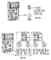
- FIG. 1C shows the hand switch setting - once switchable, permanently switchable and switchable for a limited time by means of a hand switch - as is known from the prior art.
- the present new differs from the usual time control by the possibility that by pressing the " ⁇ 1h” button the time control can be shifted from the built-in clock by + 1h, -2h, + 1h etc. This is effected by means of an intermediate time memory, the content of which is set additively changed by means of a sliding memory.
- the switch to the succeeds in the present case first or at least the second time In contrast to the usual summer-winter switching arrangements, which have the disadvantage that the operator does not know whether to set the time before or after and therefore has to correct or even re-enter in the worst case, the switch to the succeeds in the present case first or at least the second time.
- the time on the new device is either one hour forward or two hours back - and then advanced again by one hour, so that you can easily see whether the desired change has been made or whether you have to press the button again (Fig. 1C) cf. Fig. 4.
- the holiday (pseudo-Sundays) program represents a program-technical extension; with the days of the week, which form a kind of short vacation within an uninterrupted sequence, and should receive the same programs, e.g. B. that of a Sunday, through such days, e.g. B. Sundays, are to be replaced.
- the measures required in this regard are to be regarded as hardware-specific features and are dealt with in connection with FIG. 3.
- the start-up diagram offers the possibility of consistently repeating subroutines that are easy to understand, both in soft-ware and in hard-ware.
- these subroutines - as building blocks of the subroutines of the menu program - have a sub-structure in the form of a hierarchy that performs the function of setting the switching times, graduated in counters for the hours and minutes of the ON- Switch time for a channel of the output switch device of the system of the selected switch-on times in an addressable buffer by actuating an acknowledgment button via an acknowledgment module and finally the function of advancing into a subroutine of essentially the same type or - if the intended number of modules of this type has been processed - Switch to a subsequent stage in the menu by pressing the function selection key.
- the sub-function blocks differ in that they either contain a fixed block (ROM memory) for the days of the week, the advance from module to module automatically to the next position and installation of the ON and OFF switching times, as well as the position and The channels are created, or can be freely selected by means of an intermediate stage.
- the function of setting the days of the week is carried out with the help of their continuous addressing in a shift register by means of the actuating key by creating those days of the week that are to be adopted by pressing the acknowledgment key in an astable block and from there in an addressable weekly memory.
- the operating system for the user program can be optionally assembled from modules, which in the basic level are preferably two counter units in one level, acknowledgment and advance levels in expansion levels, permanent memory units for weekday blocks and finally the variants of the selectable setting one of included multiple channels.
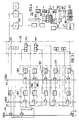
- FIG. 2 are in a block diagram between the line (101) for the control button (102) and the line (103) for the acknowledgment button (104) - input group A for signals of the switch-on time - via the AND gate (105) for the Counter (106) (hours) and the AND gate (107) for the counter (108) (minutes) can be recognized as the basic level of a subroutine module with the AND gates (112, 114) connected to outputs (115, 116) .
- An output (115) of the counter (h) is connected to the input of the AND gate (112) for the buffer (117) on the one hand and the output (116) of the counter (m) to the input of the AND gate (114) for the buffer (119) connected.
- the contents of the counters (106, 108) become the input of the AND gate (112) and corresponding to the input of the AND gate (114) and via the inputs (120, 121) acted upon the intermediate memory (117, 119).
- the counter (108) for the actuating signal at the second input of the AND gate is input via the input (125) of the AND gate (107).
- the minute input is then stored in the counter (108) and thus the output (116) and the input of the AND gate (114) are used to forward the signal at its output - which is the output of the input group "A" ( 127 ) for the switch-on times - on the buffer (119), whose output (128) via line (129) forms the second input (130) of the AND gate (131) of the input group "B" ( 132 ) with the shift register ( 133) for the position of the days of the week.
- an actuating signal can be entered by actuating the actuating key (102) via the second input, each actuation of the actuating key via line (135), the content of the displayed weekday being shown by the actuating pulse.
- Symbol is moved one place in the shift register (133) or, if the input of the displayed symbol is to be saved, to the input (140) of the AND gate (138) of the acknowledgment group ( 139 ) and when the acknowledgment key is pressed (104) a takeover command is fed via the second input and the line (141) to the buffer store (142).
- the signals for the OFF switching times are input via the input group "C” (154) for the OFF switching times, which, like the input group "A", are equipped with modules.
- the addresses are derived and stored in the weekday register (147) if the acknowledgment key (104) is actuated and then at these addresses - corresponding to the weekdays for the ON - Switching data the days of the week for the OFF switching times are saved in the days of the week register (147).
- a selection must be made by primarily pressing the signal at the output of the acknowledgment group ( 139 ), free programming of the weekdays, no longer pressing the acknowledgment key (104) of the acknowledgment group, as a result of which the output signal of the buffer (166) is NAND gate (164) and the AND gate (167) in the input of the weekday register (147) blocks.
- the acknowledgment signal negates the line (162) of the output signal of the buffer (166) to the address register (163) of the freely programmed days of the week.
- the weekday registers (143) and (147) with the associated address registers (145, 163) are together with the ON switching time registers (168) and the OFF switching time register (169) to the programming memory ( 170) summarized functionally.
- the ON switching time register (168) is loaded by the output of the counter (115) in its first digit group pair (h) (172) and from the counter output (116) the second digit group pair (m) (174).
- the OFF switching time register is loaded from the output (176) of the counter (177) of the OFF switching time input group ( 154 ) for the hours (h) and from the output (179) of the counter (180) of the minutes (m).
- the exemplary embodiment of the functional sub-program "free programming" of the times of the day and days of the week is processed by a first actuation of the function selection button, which is indicated symbolically in connection with an AND gate, and for the first cut of the ON switching times, continued by a second Actuation, which is indicated by a further AND gate, and completed by a third actuation of the Function selection button, which is explained in connection with Fig. 3.
- the connection of the function selection button (183) with the block diagram described above is shown by the line (184).
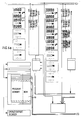
- Fig. 3 - as an extract from the complete program menu of Fig. 1A - is a block diagram of the variant of programming the ON and OFF switching times for selectable switching channels with a fixed block of z. B. seven days of the week in the manner shown in FIG. 2.
- the lines (101, 103, 184) to the actuating key (102), acknowledgment key (104) and the function selection key (183) are symbolically entered.
- the latter selects a function sub-program or a section thereof, depending on whether the function sub-program can be processed in one go or in several sections, after processing the function selection in each case.
- the button must be pressed again, after which the control button can always be pressed to address the selected sub-program.
- the weekday data permanently stored in a ROM memory (201) are stored together with the freely stored ON and OFF switching times and the channel selection data in the programming memory (170) and are stored in logical comparator units (202 ) linked to switch the result signals for the switching to the ON or OFF operating state for the extraction of the ALE link results from the registers assigned to them for the switching devices in the output together with the relevant signal.
- the sub-programs of the menus are divided into hierarchies according to function blocks and processed in stages, whereby the input groups are the same Sub-assemblies are put together, which only require comparatively clear program elements due to the fact that the logic modules, counters and buffers contained are the same.
- Fig. 3 shows that this program sequence enables consistent automatic operator guidance, in that each actuation of the actuating key indicates the actuating key input or acknowledgment required below and, conversely, each acknowledgment indicates the required subsequent input.
- the circuit logic of each part program like that of FIG.
- the device of this sub-program is composed of at least four input groups, including an hour counter (203) and a minute counter (204), separately for both ON and OFF switching times and also four Acknowledgment groups for storage in the assigned ON switch register (168) or OFF switch register (169) are composed, of which in each case an acknowledgment group (206, 207) for the hour inputs (h), which is the switching from the acknowledgment groups (206, 207) into the minute groups (204) and the other the advance (208, 209) from the ON switching times to the OFF switching times or to the channel selection data.
- the acknowledgments of the channel selection data lead to another part program by confirmation using the function selection button (183).
- switching on the device of this sub-program leads to the main stage of the ON or OFF switching time input, starting with the display of the switching time hour input as the first one requested by the display - because the days of the week are still permanently stored Input.
- FIG. 4 shows an exemplary embodiment for the time control by means of an electronic clock module ( 241 ) known per se with the time counter stages designed as counters, namely weekday stages (242), "d", hour stages (243), “h” and minute stages (244), “m”, with the clock generator (246), consisting of an oscillator (247) and various divider stages, including for 1ms, 1 / 2s, 1 / 8s and 1s clock signal outputs (T1 , T2), as well as the signals for the ongoing 1s-continuation of the electronic clock module (241).
- the time segment stages (242, 243, 244) can also be represented from the RAM in a manner which is customary in the industry.
- the clock generators (246) are released via the AND gates (266, 267) two different clock signals alternately by controlling the second inputs from a time-delayed controlled monostable FLOP element to the clock signal outputs (T1, T2) exchanged after a period of time.
- T1, T2 the clock signal outputs
- Fig. 5 is in a first group (a), (b), a second group - (c1) - (c3), (d) - and a third group (e1), (e2), (e3) divided series of display images, which is abbreviated for drawing reasons, as already expressed in Fig. 1a that these display images are made one after the other by pressing the function button (183) (Fig. 2 and 3) visible, but actually the register groups (80a, 80b, 80c, 80d etc.) with the associated programming memories (170a, 170b ...
- Fig. 1A is also included the special case in which by installing the part programs (c2) and (c3) for a more complicated programming two cases, namely for the switching times A OUT Clock five days of the week memory 03oo 12.oo Clock (Mon-Fri) freely programmable weekday memory 12.oo 16.oo Clock (Mon-Thu) - modularly composed of sub-programs - is realized for a long weekend.
- This example is representative of the multiple usability of the memory organization described, in which the entire program can be assembled in a simple manner using the loop from partial programs of different data, even if from defined formats, that is to say from program modules with parallel overlapping functions.
- the modularity extends to largely any, i.e. all data for daily ON and OFF switching data, the weeks without obligation for ON and OFF switching, as well as channels; it is only necessary to divide the entire program into program sections accordingly.
- the conditions and the formatting of the function blocks or data records are in each case - in this example: five days of the week, seven days of the week fixed and freely available Weekdays - to be taken into account, in this context - also within the framework of the hardware capacity - the programming is completely freely disposable.
- each input group contains an hour counter and a minute counter for the ON switching time group and the OFF switching time group.
- Each input branch has its own acknowledgment group (119, 117, 142) for the hour position ON, the minute position ON and the weekdays ON. Programs with fixed weekdays are naturally not acknowledged because they have not been entered.
- the channel selector group has corresponding acknowledgment groups.
- the partial memories of the intermediate register are constructed from matching memory elements in the same systematic manner as the modules described so far, cf. Fig. 2, e.g. B. an ON switching time register (168), an OFF switching time register (169), a weekday ON (143), a weekday OFF register (147), a weekday ON address register ( 145), a weekday OFF address register, and a channel selection register.
- Each acknowledgment causes the content of the next input point to be displayed on the display device, which is effected by the relevant acknowledgment group via the line concerned, so that the input is then operated.
- This operator guidance takes place both by flashing the colon after the function selection as well as after each completed entry of the ON switching time, first the hours, then the minutes, then by blinking the symbols for the days of the week, also after connecting the acknowledgment of the choice of days of the week etc., whose symbols remain. Pressing the setting buttons without prior confirmation after entering the days of the week causes the OFF switching time display to flash, Entering and acknowledging the hours and minutes - individually by themselves - causes the channel display to flash, their acknowledgment or places cause the acknowledged channel display to stop or to be replaced.
- the deletion is achieved by pressing the relevant function selection button until the relevant switching time image appears on the display device; pressing the "C” key then deletes the saved program.
- pressing the relevant function selection button For a desired change to a saved program, it is again necessary to select the relevant detail with the acknowledgment key and finally to change the detail by pressing the control key until the desired entry is made. Then the sub-program "Set time" with the function key to select, with which the entered programs are then saved.
- an additional circuit is set up in the time control group (FIG. 6), with which the time-of-day switching program brought forward and entered for a selected day, in particular Sunday, can also be processed in relation to time for other days, so z. B. for Thursday, Friday, Saturday and Sunday is processed in the same way. This is particularly advantageous for the two week (work) days between a Thursday - holiday - and Sunday.
- the relevant additional circuit - Fig. 6 - consists of a preselection counter, which is operated by the hand switch button - operated n times - for n days before Sunday this program can run.
- the preselection counter is reset after each day of the program memory by the weekday signal of the clock until the end of the reset to zero - when "FO" is displayed on the display device - e.g. B. in the line for the OFF switching times - the start of the switching program is normal again.
- the module reference symbols correspond to those in Fig. 5.
- the leaf connections of the wiring harnesses are placed in angle brackets.
- both the circuit arrangement of the new time program switching device has an extreme structure and is modular in every detail, and consequently the program parts are accordingly constructed from identical stages and components.
- this is also expressed by the fact that a single actuating key (102), a single acknowledgment key (104) and a single function selection key (183) are sufficient for operation for the selection of all sub-programs, so that each of the function groups can be selected almost in time, namely the Activate input groups, the acknowledgment groups, the ON and OFF time switch block, the day of the week selection, whereby the aforementioned three single connecting lines (101, 103, 184) are sufficient.
Abstract
Description
Die Erfindung betrifft eine elektronische digitale Schalt- und/oder Regelvorrichtung, insbesondere eine Schaltuhr, mit einer Anzeigeeinrichtung und mit einer Bedienvorrichtung für eine Einstellung der aktuellen Uhr-Zeit einer einstellbaren Uhr, für eine Sommer-Winter-Zeitumstellung, für eine Einstellung eines Ferien-Programms und für einen handeingestellten Betrieb, mit einem ersten Bedienelement für eine Programmierung und Abrufung von gespeicherten Teilprogrammen aus Speicherzellen eines Programmierspeichers und mit einem zweiten Bedienelement für eine wahlweise Eingabe und Abrufung der laufenden Zeit aus der Uhr sowie eine Eingabe von in Zählern zu speichernder Schaltzeiten und eine Abrufung darin gespeicherter Schaltzeiten, wobei durch kombinierte Betätigungen des ersten und zweiten Bedienelements diese ihnen zugeordneten Funktionen steuerbar oder beeinflußbar sind, und mit einer Vergleicher-Einheit zum Vergleichen von ausgangseitig des Speichers jeweils adressiert erscheinenden programmierten EIN- und AUS-Schaltzeiten in Stunden und Minuten einerseits und andererseits den aktuellen Uhr-Tageszeiten und Wochentagsdaten von der Uhr, wobei die gespeicherten Teilprogramme als Datensätze in Zwischenspeichern so formatiert sind, daß sie mit Hilfe mehrfacher Betätigungen der besagten Bedienelemente schrittweise einzeln aus einer organisierten Folge von Daten von seriell in adressierbar belegten oder belegbaren Registern gespeicherten Funktionsblöcken mit dem ersten Bedienelement abrufbar sind, wobei mit einem Rücksprung von einer letzten Stelle der jeweils abzurufenden Folge oder mehrerer solcher gleichartigen Folgen schleifenartig zu einer ersten Stelle der Folge gesteuert zurückgekehrt wird und wobei jeweils eine Teil-Serien-Eingabe mit einem dritten Bedienelement in ein formatiertes Register des Programmierspeichers abgespeichert und abgeschlossen wird, während dessen die Anzeige einer nächstfolgenden Programmstufe in der Anzeigeeinrichtung erfolgt oder wobei die gespeicherten Daten der Folgen jeweils mit Hilfe von in einem Befehlsspeicher enthaltenen Routinen mit periodischen Funktionsschleifen entsprechend dem betreffenden Teilprogramm mit einer überlappenden Funktion ausgelesen werden.The invention relates to an electronic digital switching and / or regulating device, in particular a time switch, with a display device and with an operating device for setting the current time of an adjustable clock, for a summer-winter time changeover, for a holiday setting. Program and for a manually set operation, with a first control element for programming and retrieving stored partial programs from memory cells of a programming memory and with a second control element for optional input and retrieval of the current time from the clock as well as an input of switching times to be stored in counters and a retrieval of switching times stored therein, these functions assigned to them being controllable or influenceable by combined actuations of the first and second operating elements, and appearing with a comparator unit for comparing addresses addressed on the output side of the memory The programmed ON and OFF switching times in hours and minutes on the one hand and the current time of day and day of the week data on the other hand, whereby the saved partial programs are formatted as data records in buffers in such a way that they can be turned off one by one using multiple actuations of the control elements an organized sequence of data from serial to addressable Function blocks stored in occupied or assignable registers can be called up with the first control element, with a return from a last position of the sequence to be called up or a plurality of such similar sequences being returned in a loop-like manner to a first position in the sequence and with a partial series input in each case a third control element is stored in a formatted register of the programming memory and is completed, during which the display of a next program stage takes place in the display device or wherein the stored data of the sequences are each with the help of routines contained in a command memory with periodic function loops in accordance with the relevant partial program with a overlapping function can be read out.
Eine derartige Schaltuhr ist aus DE-A-3 123 711 bekannt. Diese enthält einen Speicher, in den eine Folge von Schaltzeitpunkten eingebbar ist, wozu diese mittels Tastenbetätigung in einen Zwischenspeicher eingegeben und auf einer Anzeigevorrichtung dargestellt werden und nach einer automatischen Zulässigkeitsprüfung mit einer Funktionstastenbetätigung in den Speicher eingeschrieben werden. Mittels Betätigungen einer Lesetaste lassen sich die Schaltzeitpunkte nacheinander aus dem Speicher in den Zwischenspeicher auslesen und zur Anzeige bringen. Diese beschränkten Steuerungsmöglichkeiten der Programmierung sind nur für einfache Aufgaben geeignet.Such a timer is known from DE-A-3 123 711. This contains a memory into which a sequence of switching times can be entered, for which purpose these are entered into a buffer memory by means of key actuation and displayed on a display device and, after an automatic admissibility check, are written into the memory with a function key actuation. By actuating a read button, the switching times can be read out from the memory into the buffer memory one after the other and displayed. These limited control options for programming are only suitable for simple tasks.
Weiterhin ist eine elektronische Schaltuhr für digitale Schalt- und Regelaufgaben durch die DE-A-32 14 372 bekannt, die eine Bedieneinrichtung mit einer Tastatur und darin als Bedienelemente mehrere Tastschalter aufweist, womit alle vorgesehenen EIN- und AUS-Schaltzeiten, Schaltkanäle, die zugeordneten Wochentage usw. zu jedem Zeitpunkt und unabhängig voneinander, d.h. parallel, und korrigierbar eingestellt werden können. Naturgemäß ist hierfür ein hoher schaltungstechnischer Aufwand unverzichtbar.Furthermore, an electronic time switch for digital switching and control tasks is known from DE-A-32 14 372, which has an operating device with a keyboard and therein a plurality of pushbutton switches as operating elements, with which all the provided ON and OFF switching times, switching channels, are assigned Days of the week etc. at any time and can be set independently, ie in parallel, and correctable. Naturally, a high outlay on circuitry is essential for this.
Weiterhin ist aus der EP-A-0 197 336 eine elektronische Schaltuhr bekannt, deren Aufwand an Bedienelementen extrem, nämlich zwei Taster, reduziert ist, so daß die verständlicherweise zahlreichen Einstellmaßnahmen im Laufe einer zwingend notwendigen öfteren Wiederholung der mehr oder weniger großen Zahl von Betätigungen der Bedienelemente durchgeführt werden müssen. Es ist leicht erkennbar, daß dabei häufig Fehleinstellungen unvermeidbar sind und entsprechend wiederholte umständliche Korrekturen in Kauf genommen werden müssen.Furthermore, from EP-A-0 197 336 an electronic time switch is known, the expenditure on operating elements is extremely reduced, namely two buttons, so that the understandably numerous adjustment measures in the course of an absolutely necessary repeated repetition of the more or less large number of operations the controls must be performed. It is easy to see that incorrect settings are often unavoidable and that repeated, cumbersome corrections have to be accepted.
Der vorliegenden Erfindung liegt die Aufgabe zugrunde, die eingangs bezeichnete Vorrichtung bezüglich der Bedienbarkeit, d.h. der Einstellung und Wahl von Programmen, übersichtlicher und einfacher zu gestalten und damit die Bedienung wesentlich zu beschleunigen.The object of the present invention is to improve the operability, i.e. the setting and selection of programs, clearer and easier to design and thus to speed up the operation significantly.
Diese Aufgabe wird dadurch gelöst, daß die genannten Register, die genannten Zähler und die genannten Zwischenspeicher, jeweils gemäß einer hierarchischen Ordnung dieser Register, Zähler und Zwischenspeicher durch eine Formatierung der adressierbaren Speicherzellen in vorbestimmbarer Reihenfolge bei, gegebenenfalls wiederholter, Betätigung eines zweiten der Bedienelemente für eine Serie von eingestellten Werten bearbeitbar sind, so
- daß der jeweilige Programmzweig mit der zweiten Bedieneinheit für den Zähler für den Wochentag der AUS-Schalter über einen Vergleicher für seinen Inhalt und den EIN-Schalt-Wochentag nur bei dem Vergleichsergebnis, daß die AUS-Schaltzeit größer als die EIN-Schaltzeit ist, übereinstimmend mit den Daten des EIN-Schalt-Wochentags automatisch übernommen wird, und bei dem Vergleichsergebnis, daß die AUS-Schaltzeit kleiner als die EIN-Schaltzeit ist, die AUS-Schaltzeit auf den folgenden Wochentag umgestellt wird,
und/oder - daß der Speicher für die Stunden mit einem Umschalter zwischen zwei benachbarten, um eine Stunde verschiedenen Stelle oder gegebenenfalls um ein Vielfacher davon versetzten Speicherstellen verbunden ist, der mit Hilfe der Sommer/Winter-Schaltung, insbesondere einer "±1h"-Taste über einen Schalter zwischen den Stufen +1h, -2h, +1h und gegebenenfalls zurück +1h usw. um die vorgegebene Zeitspanne versetzbar ist,
und/oder - daß in eine vorgewählte Folge von Tagen einer vorgewählten Folge von Wochen statt der Schaltzeiten dieser programmierten Tage diejenigen programmierten Schaltzeitdaten anderer Tage, insbesondere des Sonntags, durch einen Vorwahlzähler gemäß der Auswertung einer Vergleichereinheit austauschbar einfügbar sind und hierbei ein Zähler je Wochentag fortgeschaltet wird, bis ein jeweils vorgewählter Anfangszählerstand abgearbeitet ist, wonach der normale Programmablauf fortgesetzt wird.
- that the respective program branch with the second operating unit for the counter for the day of the week, the OFF switch via a comparator for its content and the ON-switching day of the week, only in the comparison result that the OFF-switching time is greater than the ON-switching time with the data of the ON switching weekday is automatically adopted, and in the comparison result that the OFF switching time is less than the ON switching time, the OFF switching time is switched to the following day of the week,
and or - that the memory for the hours is connected to a switch between two adjacent memory locations that are different by one hour or possibly offset by a multiple thereof, using the summer / winter circuit, in particular a "± 1h" key via a switch between the stages + 1h, -2h, + 1h and, if necessary, back + 1h etc., can be moved by the specified period of time,
and or - that in a preselected sequence of days of a preselected sequence of weeks instead of the switching times of these programmed days, those programmed switching time data of other days, in particular on Sundays, can be interchangeably inserted by a preselection counter according to the evaluation of a comparator unit and one counter per weekday is advanced until a the preselected starting counter is processed, after which the normal program sequence is continued.
Weitere Ausgestaltungen der Erfindung sind Gegenstände der Unteransprüche.Further embodiments of the invention are the subject of the dependent claims.
Zur Vorrichtung gehören folgende Baugruppen:
- Eine einstellbare Uhr für die aktuelle Uhrzeit,
- eine "Sommer-/Winter"-Zeitumstellung,
- eine Einstellung eines Feiertags- (Pseudo-Sonntags-) Programms
- eine von Hand ausgelöste Einmal-Schaltung oder Dauer-Schaltung und
eine Einstellung einer Dauer-Handschaltung, die über eine bestimmbare Tageszahl (Ferien-Programm) programmierbar ist - wobei durch eine kombinierte Betätigung solcher Einstellungen deren Funktionen steuerbar oder beeinflußbar sind, und
- eine Vergleicher-Einheit zum Vergleich von Inhalten der Speicherzellen, nämlich den programmierten EIN- (I) und AUS-Schaltzeiten (O) in Stunden (h) und Minuten (m) einerseits mit den aktuellen Uhr-Tageszeiten (h, m) und Wochentagsdaten (d) andererseits.
- An adjustable clock for the current time,
- a "summer / winter" time change,
- a setting of a holiday (pseudo-Sunday) program
- a manually triggered one-time switching or permanent switching and
a setting of a permanent manual control that can be programmed via a definable number of days (vacation program) - the functions of which can be controlled or influenced by a combined actuation of such settings, and
- a comparator unit for comparing the contents of the memory cells, namely the programmed ON (I) and OFF switching times (O) in hours (h) and minutes (m) on the one hand with the current time of day (h, m) and weekday data (d) on the other hand.
Im folgenden sind Ausführungsbeispiele der Erfindung anhand der Zeichnung beschrieben; es stellen dar:
- Fig. 1A:
- Übersicht über die in einer Schleife enthaltene Folge von Teilprogrammen mit in Registern formatiert gespeicherten Funktionsblöcken gemäß einem Kombinationsexemplar des Ausführungsbeispiels der nachfolgenden Beschreibung mit folgenden auf Abfrage der Schleife nacheinander erscheinenden Display-Bildern;
- (a) IST-Zustand der gespeicherten Uhrzeit und des Wochentags,
- (b) bei Bedarf: Uhrzeit stellen,
- (c) bisher hintereinander eingegebene TeilprogrammBlöcke (c1, c2, c3),
- (d) Fall der gewollten Überarbeitung der für EIN- und AUS-Schaltzeit (noch nicht vorliegende) logisch richtigen Zuordnung der Wochentage,
- (e) anschließend an die gespeicherten Teilprogramme immer abrufbar:
je eine Anzeige für 7 Tage- und 5 Tage-Woche fest,
und für ganze Woche mit allen Wochentagen frei verfügbar
(e1), (e2) und (e3),
mit den zugehörigen Teil-Routinen für einige Programm-Varianten
- Fig. 1B:
- Neben-Variante: Eingaben löschen
einzelne Eingabe, Funktionsblock, Datensatz, Teilprogramm - Fig. 1C:
- (5) Umschaltung "Sommer-/Winter-Zeit",
(6) Handschalter-Betätigungen,
(7) Kurz-Ferien-Programm (z. B. Pseudo-Sonntage); - Fig. 1D:
- Details zu Fig. 1A, Fall (d);
- Fig. 2:
- Blockschaltbild einer Variante für freie Programmierung nach Tageszeiten in Minuten, Stunden, Wochentagen wahlweise für EIN- und AUS-Schaltung, sowie Ausgangskanal;
- Fig. 3:
- Blockschaltbild einer Variante der Programmierung für festen Block von Wochentagen, freie Wahl der übrigen EIN- und AUS-Schaltdaten wie Fig. 2 in Verbindung mit Vergleicher-Einheit der Entscheidungs-Logik eines Ausgangskreises;
- Fig. 4:
- eine Variante für die sichere und bedienerfreundliche Umschaltung von Sommer- auf Winter-Zeit und umgekehrt durch die Ergänzung der Gruppe von Uhr-Baueinheiten für Zeitsignal-Versorgung;
- Fig. 5:
- ausführliche Darstellung der inneren Organisation der Speicher- und zugehörigen Ladungs-Baugruppen (Fig. 2 und 3);
- Fig. 6:
- Detailliert in Fig. 6a bis Fig.6c, Ausführungsbeispiele des neuen digitalen elektronischen Schalt- und Regel-Geräts mit einem Mikro-Computer in Kombination mit einer Schaltungsgruppe für mehrere über Adreß-Zähler und Zählereinheiten selektiv anwählbare Schleifen-Programmspeicher und deren Auswertung durch wahlweisen Betrieb gleichzeitig anwählbarer Programme.
- Fig. 1A:
- Overview of the sequence of partial programs contained in a loop with function blocks formatted in registers according to a combination example of the exemplary embodiment of the description below with the following display images appearing one after the other when the loop is queried;
- (a) actual state of the stored time and day of the week,
- (b) if necessary: set the time,
- (c) partial program blocks (c1, c2, c3) previously entered in succession,
- (d) in the case of the desired revision of the logically correct assignment of the days of the week for ON and OFF switching times (not yet available),
- (e) always available after the saved partial programs:
one ad for 7 days and 5 days a week,
and freely available for the whole week with all days of the week
(e1), (e2) and (e3),
with the associated subroutines for some program variants
- Fig. 1B:
- Secondary variant: delete entries
single entry, function block, data record, part program - 1C:
- (5) switching between "summer / winter time",
(6) hand switch operations,
(7) short vacation program (e.g. pseudo Sundays); - Fig. 1D:
- 1A, case (d);
- Fig. 2:
- Block diagram of a variant for free programming according to times of the day in minutes, hours, days of the week optionally for ON and OFF switching, as well as output channel;
- Fig. 3:
- Block diagram of a variant of the programming for a fixed block of days of the week, free choice of the other ON and OFF switching data as Fig. 2 in Connection with comparator unit of the decision logic of an output circuit;
- Fig. 4:
- a variant for the safe and user-friendly changeover from summer to winter time and vice versa by adding the group of clock modules for time signal supply;
- Fig. 5:
- detailed representation of the internal organization of the storage and associated charge assemblies (Fig. 2 and 3);
- Fig. 6:
- In detail in FIGS. 6a to 6c, exemplary embodiments of the new digital electronic switching and control device with a microcomputer in combination with a circuit group for several loop program memories which can be selected selectively via address counters and counter units and their evaluation by optional operation programs that can be selected simultaneously.
Fig. 1A zeigt das Ablaufdiagramm des aus verschieden disponierbaren Teilprogrammen, die ebenfalls als Folgen von Funktionsblöcken durch Betätigung des betreffenden Bedienungselements in die Anzeigeeinrichtung nacheinander einzeln- mit der Funktionswahltaste (183) als erstem Bedienelement - abrufbar, durch Eingaben - mit der Stelltaste (102) - ladbar und veränderbar und in Registern eines zugehörigen Arbeitsspeichers - mit dem Quittungstaster (104) - weiterleitbar sind, zusammengesetzten Programm-Menüs und den zugehörigen Bedienungsarten:
Menü-Stufen, vorgesehen für vorzugsweise Bedienung durch den Installateur:
- 1. Vorbereitung der Arbeit mit der Schleife des Programm-Menüs:
- (a) Anzeige der Ursprungs-Einstellung Uhrzeit und Wochentag;
- (b) bei Bedarf: Uhrzeit stellen;
- 2. eigentliche Auswertung der übrigen Komponenten der Schleife:
- (c) Anfrage der Bilder von Datensätzen bereits eingegebener Teilprogramme:
- (c1) Blockprogramm mit fester Woche (7 Tage) Mo. - So.,
- (c2) Blockprogramm mit fester Woche (5 Tage) Mo. - Fr.,
- (c3) frei eingegebener Block - Wochentage wahlweise,
- (d) noch Anfrage:
bei diesem Beispiel ist angenommen, daß eine Überarbeitung notwendig ist; (EIN- und AUS-Schaltzeit logisch richtig zugeordnet),
- (c) Anfrage der Bilder von Datensätzen bereits eingegebener Teilprogramme:
- 3. (e) ursprünglich immer und nachher auch: Masken von formatierten Zeitmustern (00.00) und Wochentage-Mustern (- - - ... -):
- (e1) Wochentage-Block (7 Tage fest) (Mo. - So.)
- (e2) Wochentage-Block (5 Tage fest) (Mo. - Fr.)
- (e3) Wochentage wahlfrei wie Schaltzeiten und Kanäle
- Fig. 1B
- Neben-Variante: Eingabe löschen
einzelne Eingabe
Funktionsblock
Datensatz
Teilprogramm - Fig. 1C
- Menü-Stufen bzw. -Details, vorzugsweise vorgesehen für Bedienung vom Anwender:
- 5. Umschaltung Sommer-Winter-Zeit
- 6. Handschalter-Betätigungen einmal schaltend, Dauer-EIN/Dauer-AUS zeitlich begrenzt (permanent) programmiert vorgegeben
- 7. Kurz-Ferien-Programm (z. B. Pseudo-Sonntage)
Menu levels, intended for preferred operation by the installer:
- 1. Preparing to work with the loop of the program menu:
- (a) display of the original setting of time and day of the week;
- (b) if necessary: set the time;
- 2. actual evaluation of the other components of the loop:
- (c) Inquiry of the images of data records of already entered partial programs:
- (c1) Block program with a fixed week (7 days) Mon.-Sun.,
- (c2) Block program with a fixed week (5 days) Mon.-Fri.,
- (c3) freely entered block - weekdays optionally,
- (d) still request:
in this example it is assumed that a revision is necessary; (Logically correctly assigned ON and OFF switching times),
- (c) Inquiry of the images of data records of already entered partial programs:
- 3. (e) originally always and afterwards: masks of formatted time patterns (00.00) and weekday patterns (- - - ... -):
- (e1) Weekday block (7 days fixed) (Mon.-Sun.)
- (e2) Weekday block (5 days fixed) (Mon. - Fri.)
- (e3) Days of the week, such as switching times and channels
- Figure 1B
- Secondary variant: delete input
single entry
Function block
record
Sub-program - 1C
- Menu levels or details, preferably intended for user operation:
- 5. Switching between summer and winter time
- 6. Switching manual switch actuations once, permanently ON / permanently OFF programmed for a limited time (permanently)
- 7. Short vacation program (e.g. pseudo Sundays)
Die Baugruppen (83, 85, 87) sind unter Fig. 5 näher beschrieben.The assemblies (83, 85, 87) are described in more detail in FIG. 5.
Nach Durchlauf der weiteren Datensätze, falls noch solche endgültig programmiert sind, oder weiterer Anfrage der verbleibenden Masken, springt der Zustand der Schleife auf ihren Anfang zurück. Die so festgelegten einzelnen Stufen der programmierten bzw. gespeicherten Datensätze werden dann automatisch von der Verarbeitungs-Elektronik gemäß dem gespeicherten Programm abgearbeitet.After the further data records have been run through, if such have finally been programmed, or a further request for the remaining masks, the state of the loop jumps back to its beginning. The individual stages of the programmed or stored data records thus defined are then automatically processed by the processing electronics in accordance with the stored program.
Das Anlaufdiagramm der verschieden disponierbaren Teilprogramme in Fig. 1A ist aufgebaut auf wählbaren Betätigungen der Funktionswahltasten, der Stell-Tasten in verschieden serieller Kombination und in durchgehender Folge
- (a) bei festvorgegebenem Block von Wochentagen und in Erweiterung von jeweiliger Betätigung der Stelltasten in Kombination mit Quittierung bei Anzeige der EinschaltdatenGruppe für eine EIN-Schaltzeit und dann für eine AUS-Schaltzeit und schließlich die Kanalwahl,
sowie zum Anschluß durch Betätigung der Funktionstaste, - (b) bei freiwählbarem Block von Wochentagen zunächst für die EIN-Schaltzeit, Wochentag(e), nach einer weiteren Folge von Stell- und Quittierungstasten und Betätigung der Funktionstaste für AUS-Schaltzeit und Wochentag(e) bei Anzeige der AUS-Schaltzeitgruppe,
letztere mit logisch richtiger Anzeige der Ausschalttage nach Vergleich der Werte der EIN-Schaltdaten mit denen der AUS-Schaltdaten oder durch zusätzliche Betätigung der Stelltaste vor der Quittierung anschließend an die nochmalige Betätigung der Funktionstaste,
sowie zum Anschluß durch Betätigung der Funktionstaste und Betätigung der Stell- und Quittierungstasten für die Kanalwahl,
sowie zum Anschluß durch Betätigung der Funktionstaste und Rückkehr ins Menü.
- (a) with a specified block of days of the week and in extension of the respective actuation of the setting buttons in combination with acknowledgment when the switch-on data group is displayed for an ON switching time and then for an OFF switching time and finally the channel selection,
as well as for connection by pressing the function key, - (b) in the case of a freely selectable block of days of the week, initially for the ON switching time, day of the week (e), after a further sequence of actuating and acknowledgment keys and actuation of the function key for OFF switching time and day of the week (e) when the OFF switching time group is displayed,
the latter with a logically correct display of the switch-off days after comparing the values of the switch-on data with those the OFF switching data or by pressing the control button before acknowledging after pressing the function button again,
as well as for connection by pressing the function key and the actuating and acknowledgment keys for channel selection,
and for connection by pressing the function key and returning to the menu.
Jedes Teilprogramm des Programm-Menüs und gegebenenfalls jedes seiner Teilabschnitte ist getrennt durch Betätigung der Funktionswahltaste abzuschließen, wodurch die Eingabe eines anderen Teilprogramms freigegeben wird. Jedes der komplett eingegebenen Teilprogramme wird der Reihe nach durch mehrmalige Betätigung der Funktionswahltaste ("Uhr"-Symbol gekennzeichnet) als vollständiges Bild auf der Anzeige-Einrichtung angezeigt, bis die Funktionswahl zum ersten Teilspeicher des Menüs zurückkehrt. Bei vollem Anwender-Programmspeicher wird dies angezeigt.Each sub-program of the program menu and, if applicable, each of its sub-sections must be closed separately by pressing the function selection key, which enables the input of another sub-program. Each of the completely entered partial programs is displayed in succession by repeatedly pressing the function selection key (marked "clock" symbol) as a complete image on the display device until the function selection returns to the first partial memory of the menu. This is displayed when the user program memory is full.
Die Programmierung läuft, wie man sieht, mit einer abwechselnden Folge der Betätigung der Funktionstaste - zu Beginn einer Serie einmalig mit blinken - und der Stelltaste - ein- oder mehrmalig - und des Quittierungstasters - einmalig - worauf das nächste zur Eingabe freigegebene Bild des Menüs blinkt.As can be seen, the programming runs with an alternating sequence of pressing the function key - once at the beginning of a series with flashing - and the setting key - once or several times - and the acknowledgment key - once - after which the next picture of the menu released for input flashes .
Die Anfangsstation des Programm-Menüs wird durch das Bild "Montag, 0 Uhr" und durch nicht-gefüllt Kreise als Symbole für "Kanal" angezeigt; ein Doppelpunkt zwischen Stunden- und Minuten-Anzeige blinkt. Nach erster Betätigung der Funktionswahltaste erscheint das "Uhr-Symbol" für die Weisung "Uhrzeit stellen".The starting point of the program menu is indicated by the picture "Monday, midnight" and by empty circles as symbols for "channel"; a colon between the hour and minute display flashes. After pressing the function selection key for the first time, the "clock symbol" appears for the instruction "set time".
Wiederholtes Betätigen der Stelltaste bewirkt eine Zunahme der Stundenanzeige jeweils "um 1" aufwärts und fortdauernde Betätigung ein automatisches Weiterzählen - nach einer gewissen Wartezeit - beschleunigt und zwar so lange, bis die Stelltaste losgelassen wird; dies entspricht dem Stand der Technik. Wenn der Sollwert erreicht ist, wird er durch Betätigen der Quittierungstaste in den zuständigen Speicher übernommen, wonach die nachfolgende Anzeige - hier die Minuten-Anzeige - blinkt. Nach nachmaliger Betätigung der Stelltaste wiederholt sich die Funktion wie bei der Stundenanzeige bis zur Quittierung und Übernahme.Repeated actuation of the setting key causes the hour display to increase by "1" and continuous actuation accelerates the automatic counting - after a certain waiting time - until the setting key is released; this corresponds to the state of the art. When the setpoint has been reached, it is accepted into the relevant memory by pressing the acknowledgment key, after which the following display - here the minute display - flashes. After pressing the control button again, the function repeats itself, as with the hour display, until it is acknowledged and accepted.
Es ist das wesentliche Prinzip des neuen elektronischen digitalen Schaltgeräts, daß es auf der konsequenten mehrfachen Anwendung der vorbeschriebenen Prozedur beruht, was man ohne weiteres mit Hilfe der schematischen Übersicht der Fig. 1 und der daraus abgeleiteten Schlußfolgerung erkennt, unter welchen Bedingungen die Prozedur auf die Einstellung der Schaltzeiten für EIN- und AUS-Schaltzeit zwingenden oder freiwählbaren Wochentage und gegebenenfalls in welcher Weise auf die Kanalwahl anwendbar ist. In der einleitenden Übersicht ist schon die Unterscheidung zwischen zwingender, für EIN- und AUS-Schaltung übereinstimmender Programmierung und logisch richtiger Zuordnung der Wochentage und die für frei programmierbare Auswahl der Schalttage unabhängig von den an dieser Stelle des Programm-Menüs von der Maske bzw. dem Teilprogramm-Bild angebotenen EIN- und AUS-Schalttagen erwähnt.It is the essential principle of the new electronic digital switching device that it is based on the consequent multiple use of the procedure described above, which can be easily recognized with the aid of the schematic overview of FIG. 1 and the conclusion derived from it under which conditions the procedure applies to the Setting the switching times for ON and OFF switching times for mandatory or freely selectable days of the week and, if applicable, in what way is applicable to the channel selection. In the introductory overview, the distinction between mandatory programming that corresponds to the ON and OFF switching and logically correct assignment of the days of the week and that for freely programmable selection of the switching days is independent of the mask or the program menu at this point Sub-program picture mentioned ON and OFF switching days mentioned.
Die Spalte der Blockbilder für diese Fälle zeigt, daß diese Möglichkeit durch eine stufenweise Quittierung, sei es durch unmittelbar zusammen mit den Wochentagen für Einschaltzeit eingestellte, an die Anzeige der im dortigen Anschnitt automatisch eingestellten Wochentage für Ausschaltzeiten durch Betätigung der Quittierungstaste bewirkte Bestätigung derselben oder durch Zwischenbetätigung der Stelltaste, d.h. der unabhängig programmierten Auswahl der Wochentage und daran anschließende Quittierung eröffnet wird. Die Spalte der Blockbilder mit festgewählten Wochentagen (in einem ROM-Speicher) zeigt, daß die Stufen der Teilprogramm-Anwicklung durchgehend in einem Zuge, aus abwechselnden Folgen von Stell- und Quittierungstasten-Betätigung zusammengesetzt, abgearbeitet werden können.The column of block diagrams for these cases shows that this possibility is achieved by a step-by-step acknowledgment, either by setting the switch-on time directly together with the days of the week, or by confirming the weekdays for switch-off times automatically set in the gates there by pressing the confirmation button or by confirming the same Intermediate actuation of the set button, ie the independently programmed selection of the days of the week and the subsequent acknowledgment. The column of block diagrams with fixed days of the week (in a ROM memory) shows that the stages of the partial program processing can be processed continuously in one go, composed of alternating sequences of actuating and acknowledgment key actuation.
Diese Programmierung in Stufen erlaubt überdies einfache Korrekturen - beliebig wiederholbar im Falle irrtümlicher Bedienung - wenige Schritte, um zu der Korrekturstelle im Programm zu gelangen. In gleicher Weise sind lediglich kurze Sprünge erforderlich, um von einem Funktionsblock des Teilprogramms zum anderen oder von einem Teilprogramm zum anderen zu gelangen; auch ohne das Erfordernis der Korrekturen lassen sich auf diese Weise lediglich mittels der Funktionswahltaste Programmsprünge herbeiführen.This programming in stages also allows simple corrections - repeatable in case of erroneous operation - a few steps to get to the correction point in the program. In the same way, only short jumps are required in order to get from one function block of the partial program to another or from one partial program to another; even without the need for corrections, program jumps can only be made in this way using the function selection key.
In Fig. 1C ist aus Gründen der Übersichtlichkeit und der Vollständigkeit die Handschalter-Einstellung - einmal schaltbar, permanent umschaltbar und mittels Handschalter für eine zeitlich beschränkte Dauer schaltbar - dargestellt, wie sie vom Stand der Technik her bekannt ist.For reasons of clarity and completeness, FIG. 1C shows the hand switch setting - once switchable, permanently switchable and switchable for a limited time by means of a hand switch - as is known from the prior art.
Von der üblichen Zeitsteuerung weicht die vorliegende neue durch die Möglichkeit ab, daß durch Betätigung der "± 1h" Taste die Zeitsteuerung abweichend von der eingebauten Uhr um + 1h, -2h, +1h usw. versetzbar ist. Dies wird bewirkt durch einen Zwischen-Zeitspeicher, dessen Inhalt durch einen Schiebespeicher additiv geändert eingestellt wird. Im Gegensatz zu den üblichen Sommer-Winter-Umschaltungsanordnungen, die den Nachteil haben, daß die Bedienungsperson nicht weiß, ob sie die Zeit vor- oder nachstellen und deswegen im ungünstigsten Falle korrigieren oder sogar neu eingeben muß, gelingt im vorliegenden Falle die Umstellung auf das erste oder mindestens das zweite Mal.The present new differs from the usual time control by the possibility that by pressing the "± 1h" button the time control can be shifted from the built-in clock by + 1h, -2h, + 1h etc. This is effected by means of an intermediate time memory, the content of which is set additively changed by means of a sliding memory. In contrast to the usual summer-winter switching arrangements, which have the disadvantage that the operator does not know whether to set the time before or after and therefore has to correct or even re-enter in the worst case, the switch to the succeeds in the present case first or at least the second time.
Durch wiederholte Betätigung der Taste "± 1h" wird bei dem neuen Gerät entweder die Zeit um eine Stunde vor- oder um zwei Stunden zurück - und dann wieder um eine Stunde vorgestellt, so daß man leicht erkennen kann, ob die gewünschte Umstellung erfolgt ist oder ob man die Taste nochmal betätigen muß (Fig. 1C) vgl. Fig. 4.By repeatedly pressing the "± 1h" button, the time on the new device is either one hour forward or two hours back - and then advanced again by one hour, so that you can easily see whether the desired change has been made or whether you have to press the button again (Fig. 1C) cf. Fig. 4.
Eine programm-technische Erweiterung stellt dagegen das Ferien- (Pseudo-Sonntage)-Programm dar; mit dem Wochentage, die innerhalb ununterbrochenen Folge eine Art Kurzferien bilden, und gleiche Programme erhalten sollen, z. B. das eines Sonntags, durch solche Tage, z. B. Sonntage, ersetzt werden sollen, Die diesbezüglich notwendigen Maßnahmen sind als hard-ware-Besonderheiten zu betrachten und sind im Zusammenhang mit Fig. 3 behandelt.The holiday (pseudo-Sundays) program, on the other hand, represents a program-technical extension; with the days of the week, which form a kind of short vacation within an uninterrupted sequence, and should receive the same programs, e.g. B. that of a Sunday, through such days, e.g. B. Sundays, are to be replaced. The measures required in this regard are to be regarded as hardware-specific features and are dealt with in connection with FIG. 3.
Im vorliegenden Falle bietet sich vom Anlaufdiagramm her die Möglichkeit, Unterprogramme konsequent wiederholt einzusetzen, welche ohne weiteres verständlich sowohl in soft-ware, als auch in hard-ware darzustellen sind. Bei dem Betriebssystem des neuen digitalen Geräts weisen diese Unterprogramme - als Bausteine der Teilprogramme des Menü-Programms -, also in Form einer Hierarchie, Baugruppen auf, die die Funktion des Stellens der Schaltzeiten, abgestuft in Zählern für die Stunden und die Minuten der EIN-Schaltzeit für einen Kanal der Ausgangs-Schaltereinrichtung der Anlage der ausgewählten Einschaltzeiten in einem adressierbaren Zwischenspeicher durch Betätigung eines Quittierungstasters über einen Quittierungsbaustein bewirken und schließlich die Funktion der Fortschaltung in ein Unterprogramm im wesentlichen gleicher Art oder - falls die vorgesehen Zahl von Baugruppen dieser Art abgearbeitet ist - in eine folgende Stufe des Menüs durch Betätigung der Funktionswahltaste umschalten.In the present case, the start-up diagram offers the possibility of consistently repeating subroutines that are easy to understand, both in soft-ware and in hard-ware. In the operating system of the new digital device, these subroutines - as building blocks of the subroutines of the menu program - have a sub-structure in the form of a hierarchy that performs the function of setting the switching times, graduated in counters for the hours and minutes of the ON- Switch time for a channel of the output switch device of the system of the selected switch-on times in an addressable buffer by actuating an acknowledgment button via an acknowledgment module and finally the function of advancing into a subroutine of essentially the same type or - if the intended number of modules of this type has been processed - Switch to a subsequent stage in the menu by pressing the function selection key.
Die Unterfunktions-Blöcke unterscheiden sich dadurch, daß sie entweder für die Wochentage einen festen Block (ROM-Speicher) enthalten, wobei die Fortschaltung von Baugruppe zu Baugruppe automatisch zur nächsten der Stellung und Anlage der EIN- und AUS-Schaltzeiten, desgleichen der Stellung und Anlage der Kanäle erfolgt, oder mittels einer Zwischenstufe jeweils frei wählbar sind. In diesem Falle erfolgt die Funktion des Stellens der Wochentage mit Hilfe ihrer fortlaufenden Adressierung in einem Schieberegister mittels der Stelltaste unter Anlage derjenigen Wochentage, die übernommen werden sollen durch Betätigung der Quittierungstaste in einen astabilen Baustein und von dort in einen adressierbaren Wochenspeicher.The sub-function blocks differ in that they either contain a fixed block (ROM memory) for the days of the week, the advance from module to module automatically to the next position and installation of the ON and OFF switching times, as well as the position and The channels are created, or can be freely selected by means of an intermediate stage. In this case, the function of setting the days of the week is carried out with the help of their continuous addressing in a shift register by means of the actuating key by creating those days of the week that are to be adopted by pressing the acknowledgment key in an astable block and from there in an addressable weekly memory.
Das Betriebssystem für das Anwender-Programm kann aus Baugruppen wahlweise zusammengefügt werden, die in der Grundstufe vorzugsweise zwei Zählereinheiten in einer Stufe, Quittierungs- und Fortschalt-Stufen in Erweiterungsstufen, Festspeicher-Einheiten für Wochentags-Blöcke und schließlich die Varianten der wählbaren Einstellung eines von mehreren Kanälen enthalten.The operating system for the user program can be optionally assembled from modules, which in the basic level are preferably two counter units in one level, acknowledgment and advance levels in expansion levels, permanent memory units for weekday blocks and finally the variants of the selectable setting one of included multiple channels.
In Fig. 2 sind in einem Blockschaltbild zwischen der Leitung (101) für den Stelltaster (102) und der Leitung (103) für den Quittierungstaster (104) - Eingabegruppe A für Signale der Einschaltzeit - über das UND-Glied (105) für den Zähler (106) (Stunden) und das UND-Glied (107) für den Zähler (108) (Minuten) als Grundstufe eines Unterprogramm-Bausteins mit den jeweils an Ausgängen (115, 116) angeschlossenen UND-Gliedern (112, 114) erkennbar. Ein Ausgang (115) des Zählers (h) ist mit dem Eingang des UND-Glieds (112) für den Zwischenspeicher (117) einerseits und der Ausgang (116) des Zählers (m) mit dem Eingang des UND-Glieds (114) für den Zwischenspeicher (119) verbunden. In beiden Fällen werden mit dem Inhalt der Zähler (106, 108) infolge der kurzen oder längeren Betätigung des Stelltasters (102) der Eingang des UND-Glieds (112) und entsprechend der Eingang des UND-Glieds (114) und über die Eingänge (120, 121) die Zwischenspeicher (117, 119) beaufschlagt.In Fig. 2 are in a block diagram between the line (101) for the control button (102) and the line (103) for the acknowledgment button (104) - input group A for signals of the switch-on time - via the AND gate (105) for the Counter (106) (hours) and the AND gate (107) for the counter (108) (minutes) can be recognized as the basic level of a subroutine module with the AND gates (112, 114) connected to outputs (115, 116) . An output (115) of the counter (h) is connected to the input of the AND gate (112) for the buffer (117) on the one hand and the output (116) of the counter (m) to the input of the AND gate (114) for the buffer (119) connected. In both cases, the contents of the counters (106, 108) become the input of the AND gate (112) and corresponding to the input of the AND gate (114) and via the inputs (120, 121) acted upon the intermediate memory (117, 119).
Durch das Ausgangssignal des Zwischenspeichers (117), das die Übernahme der Eingabe in den Zähler (106) bestätigt, wird über den Eingang (125) des UND-Glieds (107) der Zähler (108) für das Stellsignal am zweiten Eingang des UND-Glieds (107) freigegeben. Daran anschließend erfolgt die Speicherung der Minuten-Eingabe im Zähler (108) und somit wird über dessen Ausgang (116) und den Eingang des UND-Glieds (114) die Weitergabe des Signals an seinem Ausgang - der den Ausgang der Eingabegruppe "A" (127) für die Einschaltzeiten bildet - auf den Zwischenspeicher (119), dessen Ausgang (128) über die Leitung (129) den zweiten Eingang (130) des UND-Glieds (131) der Eingabegruppe "B" (132) mit dem Schieberegister (133) für die Stellung der Wochentage herbeigeführt.Through the output signal of the buffer (117), which confirms the transfer of the input into the counter (106), the counter (108) for the actuating signal at the second input of the AND gate is input via the input (125) of the AND gate (107). Link (107) released. The minute input is then stored in the counter (108) and thus the output (116) and the input of the AND gate (114) are used to forward the signal at its output - which is the output of the input group "A" ( 127 ) for the switch-on times - on the buffer (119), whose output (128) via line (129) forms the second input (130) of the AND gate (131) of the input group "B" ( 132 ) with the shift register ( 133) for the position of the days of the week.
Nach der erwähnten Freigabe der Wochentage-Eingabe und der Anzeige ihres Bildes kann durch Betätigung der Stelltaste (102) über den zweiten Eingang je Betätigung der Stelltaste über die Leitung (135) ein Stellsignal eingegeben werden, wobei durch den Stellimpuls der Inhalt des angezeigten Wochentags--Symbol jeweils um eine Stelle in dem Schieberegister (133) weitergeschoben wird, oder, wenn die Eingabe des angezeigten Symbols gespeichert bleiben soll, auf den Eingang (140) des UND-Glieds (138) der Quittierungsgruppe (139) und bei Betätigung der Quittierungstaste (104) ein Übernahmekommando über den zweiten Eingang und die Leitung (141) dem Zwischenspeicher (142) zugeführt wird. Der gleiche Vorgang läuft bei jeder nachfolgenden Betätigung der Stelltaste für die anderen Wochentage ab und die Anzeige wird von Tag zu Tag verschoben aktualisiert oder die Übernahme wird jeweils durch das Signal der Quittierungstaste in den Zwichenspeicher (142) übergeben. In gleicher Weise werden alle Signale der ausgewählten Wochentage in das Wochentageregister (143) unter Adressierung durch die Eingangssignale auf der Leitung (135) über die Leitung (144) mittels des Adress-Registers (145) abespeichert.After the aforementioned release of the day of the week entry and the display of your picture, an actuating signal can be entered by actuating the actuating key (102) via the second input, each actuation of the actuating key via line (135), the content of the displayed weekday being shown by the actuating pulse. Symbol is moved one place in the shift register (133) or, if the input of the displayed symbol is to be saved, to the input (140) of the AND gate (138) of the acknowledgment group ( 139 ) and when the acknowledgment key is pressed (104) a takeover command is fed via the second input and the line (141) to the buffer store (142). The same process takes place with each subsequent actuation of the set button for the other days of the week and the display is updated from day to day or the transfer is saved in the buffer memory by the signal of the acknowledgment button (142) to hand over. In the same way, all signals of the selected days of the week are stored in the weekday register (143) with addressing by the input signals on line (135) via line (144) by means of the address register (145).
Übereinstimmend mit der Eingabe der Signale für die EIN-Schaltzeiten erfolgt die Eingabe der Signale für die AUS-Schaltzeiten über die Eingabegruppe "C" (154) für die AUS-Schaltzeiten, die gleich wie die Eingabegruppe "A" mit Bausteinen bestückt sind. Bei der Eingabe der Wochentags-Daten, wofür zunächst die in das Wochentage-Register (143) über das gleiche Adress-Register (145) aus den Signalen im Eingang des Schieberegisters (133) über die Leitung (149) zu dem ersten Eingang des NAND-Glieds (151) der Quittierungs-Gruppe (152) die Adressen abgeleitet und in das Wochentage-Register (147) eingespeichert wird, falls die Quittierungs-Taste (104) betätigt wird und dann an diesen Adressen - übereinstimmend mit den Wochentagen für die EIN-Schaltdatendie Wochentage für die AUS-Schaltzeiten in das Wochentage-Register (147) gespeichert werden.In accordance with the input of the signals for the ON switching times, the signals for the OFF switching times are input via the input group "C" (154) for the OFF switching times, which, like the input group "A", are equipped with modules. When entering the day of the week data, for which the first in the weekday register (143) via the same address register (145) from the signals in the input of the shift register (133) via the line (149) to the first input of the NAND Member (151) of the acknowledgment group ( 152 ), the addresses are derived and stored in the weekday register (147) if the acknowledgment key (104) is actuated and then at these addresses - corresponding to the weekdays for the ON - Switching data the days of the week for the OFF switching times are saved in the days of the week register (147).
Hierbei ist noch die Variante zu erläutern, bei der die identisch gespeicherte Wochentage-Eingabe in das Wochentage-Register (147) bei Nicht-Betätigung der Quittierungs-Taste (104) das Signal am Ausgang der Eingabegruppe "C" (154), die gleichartig ist zu der Eingabegruppe "A" (127), aber für die AUS-Schaltzeiten bestimmt ist, über den ersten Eingang (156) des UND-Glieds (157) der Eingabegruppe "D" (146) durch die Betätigung der Stelltaste (102) über die Leitung (158) durch ein Schieberegister (159) ausgebildeten Zähler in gleicher Weise bei den Wochentagen aktiviert wird, die in das Programm übernommen werden sollen, Ausgangssignale für die ausgewählten Wochentage über die Quittierungs-Gruppe (161) und die Leitung (162), die NAND-Glieder (164, 151) dem Wochentage-Register (147) zugeleitet werden. In diesem Falle sind also auch AUS-Schalt-Wochentage frei programmierbar.Here is the variant to be explained, in which the identically stored weekday entry in the weekday register (147) when the acknowledgment key (104) is not pressed, the signal at the output of the input group "C" (154), which is similar is to the input group "A" (127), but is intended for the OFF switching times, via the first input (156) of the AND gate (157) of the input group "D" ( 146 ) by pressing the actuating key (102) Via the line (158), a counter formed by a shift register (159) is activated in the same way for the days of the week to be included in the program, output signals for the selected days of the week via the acknowledgment group ( 161 ) and the line (162) who have favourited NAND Links (164, 151) to the Weekday registers (147) are sent. In this case, OFF switching weekdays are also freely programmable.
Für beide Varianten muß eine Auswahl getroffen werden, indem vorrangig das Signal am Ausgang der Quittierungs-Gruppe (139) die freie Programmierung der Wochentage nicht mehr Quittierungstaste (104) der Quittierungs-Gruppe bereits betätigt ist, wodurch das Ausgangssignal des Zwischenspeichers (166) das NAND-Glied (164) und das UND-Glied (167) im Eingang des Wochentage-Registers (147) sperrt. Andererseits gibt das Quittierungssignal negiert die Leitung (162) des Ausgangssignals des Zwischenspeichers (166) zum Adreß-Register (163) der frei-programmierten Wochentage frei.For both variants, a selection must be made by primarily pressing the signal at the output of the acknowledgment group ( 139 ), free programming of the weekdays, no longer pressing the acknowledgment key (104) of the acknowledgment group, as a result of which the output signal of the buffer (166) is NAND gate (164) and the AND gate (167) in the input of the weekday register (147) blocks. On the other hand, the acknowledgment signal negates the line (162) of the output signal of the buffer (166) to the address register (163) of the freely programmed days of the week.
Die Wochentage-Register (143) und (147) mit den zugehörigen Adreß-Registern (145, 163) sind zusammen mit den EIN-Schaltzeit-Registern (168) und dem AUS-Schaltzeit-Register (169) zu dem Programmierungs-Speicher (170) funktionsmäßig zusammengefaßt. Das EIN-Schaltzeit-Register (168) wird von dem Ausgang des Zählers (115) in seinem ersten Stellengruppenpaar (h) (172) und aus dem Zählerausgang (116) das zweite Stellengruppenpaar (m) (174) geladen. In gleicher Weise erfolgt die Ladung des AUS-Schaltzeit-Registers vom Ausgang (176) des Zählers (177) der AUS-Schaltzeit-Eingabegruppe (154) für die Stunden (h) und vom Ausgang (179) des Zählers (180) der Minuten (m).The weekday registers (143) and (147) with the associated address registers (145, 163) are together with the ON switching time registers (168) and the OFF switching time register (169) to the programming memory ( 170) summarized functionally. The ON switching time register (168) is loaded by the output of the counter (115) in its first digit group pair (h) (172) and from the counter output (116) the second digit group pair (m) (174). In the same way, the OFF switching time register is loaded from the output (176) of the counter (177) of the OFF switching time input group ( 154 ) for the hours (h) and from the output (179) of the counter (180) of the minutes (m).
Das Ausführungsbeispiel für das Funktions-Teilprogramm "freie Programmierung" der Tageszeiten und Wochentage wird abgearbeitet durch eine erste Betätigung der Funktionswahltaste, die symbolisch in Verbindung mit einem UND-Glied angedeutet ist, und für den ersten Anschnitt der EIN-Schaltzeiten, fortgesetzt durch eine zweite Betätigung, die durch ein weiteres UND-Glied angedeutet ist, und abgeschlossen durch eine dritte Betätigung des Funktionswahltasters, die in Verbindung mit Fig. 3 erläutert wird. Der Zusammenhang des Funktionswahltasters (183) mit dem vorbeschriebenen Blockschaltbild ist durch die Leitung (184) dargestellt.The exemplary embodiment of the functional sub-program "free programming" of the times of the day and days of the week is processed by a first actuation of the function selection button, which is indicated symbolically in connection with an AND gate, and for the first cut of the ON switching times, continued by a second Actuation, which is indicated by a further AND gate, and completed by a third actuation of the Function selection button, which is explained in connection with Fig. 3. The connection of the function selection button (183) with the block diagram described above is shown by the line (184).
In Fig. 3 ist - als Auszug aus dem vollständigen Programm-Menü der Fig. 1A - ein Blockschaltbild der Variante einer Programmierung der EIN- und AUS-Schaltzeiten für wählbare Schaltkanäle bei festem Block von z. B. sieben Wochentagen in der Art der Darstellung der Fig. 2 wiedergegeben. Wie dort sind symbolisch die Leitungen (101, 103, 184) zu der Stelltaste (102), Quittierungstaste (104) und dem Funktionswahl-Taster (183) eingetragen. Durch letztere wird, wie im Zusammenhang mit Fig. 1A erläutert ist, ein Funktions-Teilprogramm oder ein Anschnitt davon ausgewählt, je nachdem, ob das Funktions-Teilprogramm in einem Zuge abgearbeitet werden kann oder in mehreren Anschnitten, nach deren Anarbeitung jeweils der Funktionswahl-Taster erneut betätigt werden muß, wonach dann immer der Stelltaster betätigt werden kann, um das gewählte Teilprogramm anzusprechen.In Fig. 3 - as an extract from the complete program menu of Fig. 1A - is a block diagram of the variant of programming the ON and OFF switching times for selectable switching channels with a fixed block of z. B. seven days of the week in the manner shown in FIG. 2. As there, the lines (101, 103, 184) to the actuating key (102), acknowledgment key (104) and the function selection key (183) are symbolically entered. The latter, as explained in connection with FIG. 1A, selects a function sub-program or a section thereof, depending on whether the function sub-program can be processed in one go or in several sections, after processing the function selection in each case. The button must be pressed again, after which the control button can always be pressed to address the selected sub-program.
Die fest in einem ROM-Speicher (201) abgelegten Wochentags-Daten sind zusammen mit den frei eingespeicherten EIN- und AUS-Schaltzeiten und den Kanalwahl-Daten in dem Programmierungsspeicher (170) abgelegt und werden von dort aus in logischen Vergleicher-Einheiten (202) verknüft, um für die Entnahme der ALE-Verknüpfungs-Ergebnisse den diesen zugeordneten Registern für die Schaltvorrichtungen im Ausgang zusammen mit dem betreffenden Signal die Ergebnissignale für die Schaltung auf den EIN- bzw. AUS-Betriebszustand zu schalten.The weekday data permanently stored in a ROM memory (201) are stored together with the freely stored ON and OFF switching times and the channel selection data in the programming memory (170) and are stored in logical comparator units (202 ) linked to switch the result signals for the switching to the ON or OFF operating state for the extraction of the ALE link results from the registers assigned to them for the switching devices in the output together with the relevant signal.
Die Teilprogramme der Menüs werden, wie bereits beschreiben, in Hierarchie nach Funktionsblöcken aufgeteilt, stufenweise abgearbeitet, wobei die Eingabegruppen aus gleichen Unterbaugruppen zusammengewtellt sind, die wegen der Gleichheit der enthaltenen logischen Bausteine, Zähler und Zwischenspeicher lediglich vergleichsweise übersichtlicher Programmelemente bedürfen.As already described, the sub-programs of the menus are divided into hierarchies according to function blocks and processed in stages, whereby the input groups are the same Sub-assemblies are put together, which only require comparatively clear program elements due to the fact that the logic modules, counters and buffers contained are the same.
Fig. 3 zeigt, daß dieser Programmablauf eine konsequente automatische Bedienungsführung ermöglicht, indem jede Stelltasten-Betätigung der im folgenden geforderten Stelltasten-Eingabe oder Quittierung anzeigt und umgekehrt jede Quittierung die geforderte nachfolgende Eingabe anzeigt. Die Schaltungs-Logik jedes Teilprogramms ist wie diejenige der Fig. 3 mindestens aus vier Eingabegruppen zusammengesetzt, darunter je einem Stunden-, (203) und je einem Minutenzähler (204) und zwar getrennt sowohl für EIN-als auch AUS-Schaltzeiten und ebenfalls vier Quittierungs-Gruppen zur Einspeicherung in das zugeordnete EIN-Schalt-Register (168) oder AUS-Schalt-Register (169) zusammengesetzt, von denen jeweils eine Quittierungsgruppe (206, 207) für die Stunden-Eingaben (h), welche das Fortschalten von den Quittierungsgruppen (206, 207) in die Minutengruppen (204) und die andere die Fortschaltung (208, 209) von den EIN-Schaltzeiten zu den AUS-Schaltzeiten bzw. zu den Kanalwahl-Daten bewirkt. Entsprechend führen die Quittierungen der Kanalwahldaten zu einem anderen Teilprogramm durch Bestätigung mittels des Funktionswahl-Tasters (183). Umgekehrt führt die Einschaltung des Geräts dieses Teilprogramm ohne weitere Stelltaster-Eingabe - weil die Wochentage doch fest eingespeichert sind - automatisch zu der Hauptstufe der EIN- bzw. AUS-Schaltzeiten-Eingabe, beginnend mit der Anzeige der Schaltzeit-Stundeneingabe als erster durch Anzeige geforderter Eingabe.Fig. 3 shows that this program sequence enables consistent automatic operator guidance, in that each actuation of the actuating key indicates the actuating key input or acknowledgment required below and, conversely, each acknowledgment indicates the required subsequent input. The circuit logic of each part program, like that of FIG. 3, is composed of at least four input groups, including an hour counter (203) and a minute counter (204), separately for both ON and OFF switching times and also four Acknowledgment groups for storage in the assigned ON switch register (168) or OFF switch register (169) are composed, of which in each case an acknowledgment group (206, 207) for the hour inputs (h), which is the switching from the acknowledgment groups (206, 207) into the minute groups (204) and the other the advance (208, 209) from the ON switching times to the OFF switching times or to the channel selection data. Correspondingly, the acknowledgments of the channel selection data lead to another part program by confirmation using the function selection button (183). Conversely, switching on the device of this sub-program leads to the main stage of the ON or OFF switching time input, starting with the display of the switching time hour input as the first one requested by the display - because the days of the week are still permanently stored Input.
Fig. 4 zeigt ein Ausführungsbeispiel für die Zeitsteuerung durch eine an sich bekannte elektronische Uhr-Baugruppe (241) mit den als Zähler ausgebildeten Zeitzähl-Stufen, nämlich Wochentagstufen (242),"d", Stundenstufen (243), "h" und Minutenstufen (244), "m", mit dem Taktgenerator (246), bestehend aus einem Oszillator (247) und verschiedenen Teilerstufen, u.a. für 1ms-, 1/2s-, 1/8s- und 1s-Taktsignal-Ausgänge (T1, T2), sowie die Signale für die laufende 1s-Fort-Schaltung der elektronischen Uhr-Baugruppe (241). Die Zeitabschnitts-Stufen (242, 243, 244) sind auch aus dem Arbeitsspeicher RAM in an sich branchenüblicher Weise darstellbar.FIG. 4 shows an exemplary embodiment for the time control by means of an electronic clock module ( 241 ) known per se with the time counter stages designed as counters, namely weekday stages (242), "d", hour stages (243), "h" and minute stages (244), "m", with the clock generator (246), consisting of an oscillator (247) and various divider stages, including for 1ms, 1 / 2s, 1 / 8s and 1s clock signal outputs (T1 , T2), as well as the signals for the ongoing 1s-continuation of the electronic clock module (241). The time segment stages (242, 243, 244) can also be represented from the RAM in a manner which is customary in the industry.
Von den Taktgeneratoren (246) werden über die UND-Glieder (266, 267) zwei verschiedene Taktsignale wechselweise durch Steuerung der zweiten Eingänge aus einem zeitverzögert gesteuerten monostabilen FLOP-Glied an die Taktsignal-Ausgänge (T₁, T₂) nach einer Zeitspanne vertauscht freigegeben. Mit dieser Schaltungsanordnung erfolgt die zeitverzögerte Umschaltung der Taktsignal-Taster-Signaleingabe bei den Stelltastern von Einzelimpulsen zu einer schnelleren Folge von Taktimpuls-Serien.The clock generators (246) are released via the AND gates (266, 267) two different clock signals alternately by controlling the second inputs from a time-delayed controlled monostable FLOP element to the clock signal outputs (T₁, T₂) exchanged after a period of time. With this circuit arrangement, the time-delayed switchover of the clock signal pushbutton signal input with the setting pushbuttons takes place from individual pulses to a faster sequence of clock pulse series.
In Fig. 5 ist durch die in einer ersten Gruppe (a), (b), eine zweite Gruppe - (c₁) - (c₃), (d) - und eine dritte Gruppe (e₁), (e₂), (e₃) aufgeteilte Reihe von Display-Bildern, die aus zeichnerischen Gründen gekürzt ist, wie schon in Fig. 1a zum Ausdruck gebracht, daß diese Display-Bilder durch Betätigung des Funktionstasters (183) (Fig. 2 und 3) nacheinander sichtbar gemacht werden, dabei aber tatsächlich die Registergruppen (80a, 80b, 80c, 80d usw.) mit den zugehörigen Progrtammierspeichern (170a, 170b... usw.) jeweils auf die BUS-Leitung zum Zwischenspeicher (83) in Ausführung der Funktionssignale (84) der Befehle der Microcomputer-Gruppe (85) mit Programmspeicher (69) mit zugehörigem Decoder, Sprungadreßspeicher usw., Zeitsignalgruppe (86), Datenspeicher (87) (Arbeits- und ggf. Extern-) und Aaithmetisch-logischer Verknüpfungs-Baueinheit (88a, 88c), - je nach Anzahl der Schaltkanäle - geschaltet und dort verarbeitet werden.In Fig. 5 is in a first group (a), (b), a second group - (c₁) - (c₃), (d) - and a third group (e₁), (e₂), (e₃) divided series of display images, which is abbreviated for drawing reasons, as already expressed in Fig. 1a that these display images are made one after the other by pressing the function button (183) (Fig. 2 and 3) visible, but actually the register groups (80a, 80b, 80c, 80d etc.) with the associated programming memories (170a, 170b ... etc.) each on the BUS line to the buffer (83) in execution of the function signals (84) of the commands of the microcomputers -Group ( 85 ) with program memory (69) with associated decoder, jump address memory, etc., time signal group ( 86 ), data memory (87) (working and possibly external) and aaithmetic-logic logic unit (88a, 88c), - depending on the number of switching channels - switched and processed there.
In Fig. 1A ist auch der Sonderfall enthalten, bei dem durch Installation der Teilprogramme (c₂) und (c₃) für eine kompliziertere Programmierung aus
also für verlängertes Wochenende realisiert ist.In Fig. 1A is also included the special case in which by installing the part programs (c₂) and (c₃) for a more complicated programming
is realized for a long weekend.
Dieses Beispiel ist stellvertretend nachweiskräftig für die vielfache Verwendbarkeit der beschriebenen Speicher-Organisation, bei der das Gesamtprogramm mit Hilfe der Schleife aus Teilprogrammen verschiedener Daten, wenn auch aus festgelegten Formaten, also aus Programm-Modulen mit parallel überlappender Funktion in einfacher Weise zusammensetzbar ist. Die Modularität erstreckt sich auf weitgehend beliebige, d.h. sämtliche Daten für Tages-EIN-und AUS-Schaltdaten, die Wochen freibleibend für EIN- und AUS-Schaltung, sowie Kanäle; es ist lediglich erforderlich, das Gesamtprogramm entsprechend in Programm-Anschnitte aufzuteilen.This example is representative of the multiple usability of the memory organization described, in which the entire program can be assembled in a simple manner using the loop from partial programs of different data, even if from defined formats, that is to say from program modules with parallel overlapping functions. The modularity extends to largely any, i.e. all data for daily ON and OFF switching data, the weeks without obligation for ON and OFF switching, as well as channels; it is only necessary to divide the entire program into program sections accordingly.
Die Display-Bilder (ei) bis (e₃) sind - so lange der Speicher nicht voll ist, was angezeigt werden kann - immer zunächst zusätzlich abrufbar und zeigen der Bedienungsperson, ob oder daß noch Kapazität für weitere Teilprogramme disponierbar ist. Dabei sind jeweils die Bedingungen und die Formatierung der Funktionsblöcke oder Datensätze - in diesem Beispiel: fünf Wochentage, sieben Wochentage fest und frei verfügbare Wochentage - zu berücksichtigen, in diesem Rahmen - auch dem Rahmen der hard-ware-Kapazität - ist die Programmeirung völlig frei disponierbar.The display images (ei) to (e₃) - as long as the memory is not full, which can be displayed - can always be called up first and show the operator whether or that capacity is still available for further sub-programs. The conditions and the formatting of the function blocks or data records are in each case - in this example: five days of the week, seven days of the week fixed and freely available Weekdays - to be taken into account, in this context - also within the framework of the hardware capacity - the programming is completely freely disposable.
Jede Eingangsgruppe enthält - wie bereits anhand von Fig. 2 erläutert ist - je einen Stundenzähler und einen Minutenzähler für die EIN-Schaltzeit-Gruppe und die AUS-Schaltzeit-Gruppe. Jeder Eingabe-Zweig hat seine eigene Quittierungsgruppe (119, 117, 142) für die Stunden-Stelle-EIN, die Minutenstelle-EIN und die Wochentage EIN. Bei den Programmen mit festen Wochentagen fehlt naturgemäß deren Quittierung, da sie nicht eingegeben worden sind. Dagegen weist die Kanalwähler-Gruppe entsprechende Quittierungs-Gruppen auf. Gleich systematisch wie die bisher beschriebenen Baugruppen sind auch die Teilspeicher des Zwischen-Registers aus übereinstimmenden Speicher-Elementen aufgebaut, vgl. Fig. 2, z. B. einem EIN-Schaltzeit-REgister (168), einem AUS-Schaltzeit-Register (169), einem Wochentage-EIN- (143), einem Wochentage-AUS-Register (147), einem Wochentage-EIN-Adreß-Register (145), einem Wochentage-AUS-Adreß-Register, und einem Kanalwahl-Register.As already explained with reference to FIG. 2, each input group contains an hour counter and a minute counter for the ON switching time group and the OFF switching time group. Each input branch has its own acknowledgment group (119, 117, 142) for the hour position ON, the minute position ON and the weekdays ON. Programs with fixed weekdays are naturally not acknowledged because they have not been entered. In contrast, the channel selector group has corresponding acknowledgment groups. The partial memories of the intermediate register are constructed from matching memory elements in the same systematic manner as the modules described so far, cf. Fig. 2, e.g. B. an ON switching time register (168), an OFF switching time register (169), a weekday ON (143), a weekday OFF register (147), a weekday ON address register ( 145), a weekday OFF address register, and a channel selection register.
Jede Quittierung führt die Anzeige des Inhalts der nächstfolgenden Eingabestelle auf der Anzeigeeinrichtung herbei, was über die betreffende Leitung von der betreffenden Quittierungsgruppe bewirkt wird, so daß dann die Bedienung der Eingaben geführt wird. Diese Führung der Bedienungsperson erfolgt sowohl
durch Blinken des Doppelpunkts nach der Funktionswahl
als auch jeweils nach Quittierung jeder abgeschlossenen Eingabe der EIN-Schaltzeit,
zuerst der Stunden, dann der Minuten,
dann durch Blinken der Symbole für die Wochentage,
ferner nach Anschluß der Quittierung der Wahl der Wochentage usw., deren Symbole stehen bleiben.
Ein Betätigen der Stelltasten ohne vorherige Quittierung nach der Eingabe der Wochentage bewirkt Blinken der AUS-Schaltzeit-Anzeige,
Eingeben und Quittierung der Stunden und Minuten - einzeln für sich - bewirkt Blinken der Kanalanzeige,
deren Quittierung oder Stellen bewirken Stehenbleiben der quittierten Kanalanzeige bzw. deren Austausch.Each acknowledgment causes the content of the next input point to be displayed on the display device, which is effected by the relevant acknowledgment group via the line concerned, so that the input is then operated. This operator guidance takes place both
by flashing the colon after the function selection
as well as after each completed entry of the ON switching time,
first the hours, then the minutes,
then by blinking the symbols for the days of the week,
also after connecting the acknowledgment of the choice of days of the week etc., whose symbols remain.
Pressing the setting buttons without prior confirmation after entering the days of the week causes the OFF switching time display to flash,
Entering and acknowledging the hours and minutes - individually by themselves - causes the channel display to flash,
their acknowledgment or places cause the acknowledged channel display to stop or to be replaced.
Bei der Anarbeitung des Programms oder der Teilprogramme werden - wie auch sonst bei Computern die Operationsteile der Befehlsworte des Programmspeichers entsprechend den Schritten des Programm-Betriebssystems - in genauer Realisierung der in der vorstehenden Aufzählung von Verknüpfungs- und logischen Eingabe- und Übertragungs-Funktionen als eine von "soft-ware-Befehlen" ebenfalls wieder mit Hilfe von Funktionen von ausgelesenen Speicher-Inhalten, deren Interpretation und deren Verknüpfung derselben in einer arithmetisch-logischen Einheit umgesetzt. Einige Programmroutinen gehen über die übliche Anarbeitung eines Programms hinaus, da die meisten Funktionen durch die Führung der Bedienungsperson rein aus der Betätigung der Bedienelemente herbeigeführt werden.When processing the program or the partial programs - as is also the case with computers, the operational parts of the command words of the program memory in accordance with the steps of the program operating system - in precise implementation of the above-mentioned combination of logic and logic input and transmission functions as one of "soft-ware instructions" again implemented with the help of functions of read memory contents, their interpretation and their combination in an arithmetic-logical unit. Some program routines go beyond the usual preparation of a program, since most of the functions are brought about by the operator's guidance purely from the actuation of the operating elements.
Das Löschen wird erreicht, indem die Betätigung der betrefenden Funktionswahl-Taste so lange erfolgt, bis das betreffende Schaltzeitbild auf der Anzeigeeinrichtung erscheint; durch Betätigung der Taste "C" wird dann das gespeicherte Programm gelöscht. Für eine gewünschte Änderung eines gespeicherten Programms ist es wiederum erforderlich, das betreffende Detail mit der Quittierungstaste anzuwählen und schließlich das Detail durch Betätigung der Stelltaste bis zur gewünschten Eingabe zu verändern. Danach ist mit der Funktionstaste das Teilprogramm "Uhrzeit stellen" anzuwählen, womit dann die eingegebenen Programme eingespeichert sind.The deletion is achieved by pressing the relevant function selection button until the relevant switching time image appears on the display device; pressing the "C" key then deletes the saved program. For a desired change to a saved program, it is again necessary to select the relevant detail with the acknowledgment key and finally to change the detail by pressing the control key until the desired entry is made. Then the sub-program "Set time" with the function key to select, with which the entered programs are then saved.
Für das "Kurzferien-Programm" ist in der Zeitsteuerungsgruppe (Fig. 6) eine Zusatzschaltung eingerichtet, mit der das für einen ausgewählten Tag, insbesondere den Sonntag, vorgezogene und eingegebene Tageszeit-Schaltprogramm auch für andere Tage im zeitlichen Zusammenhang damit abgearbeitet werden kann, also damit z. B. für den Donnerstag, den Freitag, den Samstag und den Sonntag in gleicher Weise abgearbeitet wird. Dies ist besonders vorteilhaft für die zwei Wochen-(Werk-) Tage zwischen einem Donnerstag - Feiertag - und dem Sonntag. Die diesbezügliche Zusatzschaltung - Fig. 6 - besteht in einem Vorwahlzähler, der mittels des Handschalter-Tasters - n-malig betätigt - für n Tage vor dem Sonntag dieses Programm ablaufen läßt. Der Vorwahlzähler wird nach jedem Tag des Programm-Speichers durch das Wochentag-Signal der Uhr zurückgeschaltet, bis zum Ende der Rückstellung auf null - bei der Anzeige "FO" auf der Anzeigeeinrichtung - z. B. in der Zeile für die AUS-Schaltzeiten - der Anlauf des Schaltprogramms wieder normal ist. Die Baugruppen-Referenzzeichen entsprechen denen in Fig. 5. Die Blattanschlüsse der Leitungsstränge sind in spitze Klammern gesetzt.For the "short vacation program", an additional circuit is set up in the time control group (FIG. 6), with which the time-of-day switching program brought forward and entered for a selected day, in particular Sunday, can also be processed in relation to time for other days, so z. B. for Thursday, Friday, Saturday and Sunday is processed in the same way. This is particularly advantageous for the two week (work) days between a Thursday - holiday - and Sunday. The relevant additional circuit - Fig. 6 - consists of a preselection counter, which is operated by the hand switch button - operated n times - for n days before Sunday this program can run. The preselection counter is reset after each day of the program memory by the weekday signal of the clock until the end of the reset to zero - when "FO" is displayed on the display device - e.g. B. in the line for the OFF switching times - the start of the switching program is normal again. The module reference symbols correspond to those in Fig. 5. The leaf connections of the wiring harnesses are placed in angle brackets.
Zusammenfassend ist hervorzuheben, daß sowohl die Schaltungsanordnung des neuen Zeitprogramm-Schaltgeräts extrem und bis ins Detail modular aufgebaut ist und folglich auch die Programmteile entsprechend aus identisch gleichen Stufen und Komponenten ausgebildet sind. Letzteren Endes kommt dies auch dadurch zum Ausdruck, daß eine einzige Stelltaste (102), eine einzige Quittierungstaste (104) und eine einzige Funktionswahltaste (183) zwecks Bedienung für die Auswahl aller Teilprogramme ausreichen, um jede der Funktionsgruppen nahezu zeitlich wahlweise, nämlich die Eingabegruppen, die Quittierungsgruppen, der EIN- und AUS-Zeitschaltblock, die Wochentag-Auswahl zu aktivieren, wobei die erwähnten drei einzigen Anschlußleitungen (101, 103, 184) ausreichen.In summary, it should be emphasized that both the circuit arrangement of the new time program switching device has an extreme structure and is modular in every detail, and consequently the program parts are accordingly constructed from identical stages and components. In the end, this is also expressed by the fact that a single actuating key (102), a single acknowledgment key (104) and a single function selection key (183) are sufficient for operation for the selection of all sub-programs, so that each of the function groups can be selected almost in time, namely the Activate input groups, the acknowledgment groups, the ON and OFF time switch block, the day of the week selection, whereby the aforementioned three single connecting lines (101, 103, 184) are sufficient.
Die selektive Ansprache eines digitalen elektronischen Schalt- und/oder Regel-Gerätes von mehreren kombinierten Schleifen-Programmen mit Hilfe der vorbeschriebenen stufenweisen und abschnittweisen, parallel zusammenwirkenden Programmierung läßt sich - wie man ohne weiteres erkennt - durch Vervielfachung der Speicher-Organisation von Fig. 5 in Verbindung mit Fig. 1A verwirklichen, wenn man die Leitung zu dem Funktionswahl-Taster den Eingangsgruppen der Schleife aus einer Folge von Teilprogramm-Speichern über einen Adreßverteiler mit einem Zähler, Adreßzähler und einem Rückadreßspeicher und -zähler führt, wie es in Fig. 6 in stark schematischer und vereinfachter Form dargestellt ist. Die Bezugsziffern und die Bezeichnungen lassen sich unter Zuhilfenahme der vorstehenden Beschreibung anhand insbesondere der Fig. 1A und 5 ermitteln; die Ausgangskreise des elektronischen digitalen Geräts sind von dieser Ergänzung nicht betroffen.The selective addressing of a digital electronic switching and / or regulating device of several combined loop programs with the aid of the above-described step-by-step and section-wise parallel interacting programming can - as can be readily recognized - by multiplying the memory organization of FIG. 5 realized in connection with Fig. 1A, if one leads the line to the function selection button the input groups of the loop from a sequence of partial program memories via an address distributor with a counter, address counter and a return address memory and counter, as shown in Fig. 6 is shown in a highly schematic and simplified form. The reference numbers and the designations can be determined with the aid of the above description with reference in particular to FIGS. 1A and 5; the output circuits of the electronic digital device are not affected by this addition.
Claims (7)
- Electronic digital switching and/or control device, more particularly a time switch, having a display facility and having an operator's facility for setting the current time of day on an adjustable clock for changeovers between summer and winter time, for setting a holiday programme and for manually adjusted operation, and having a first actuating element (183) for programming and recalling stored sub-programmes from storage locations of a programming memory (170) and having a second actuating element (162) for optional input and recall of the running time from the clock and also for the input of switching times to be stored in counters (106, 108, 177, 180, 133, 159) and the recall of switching times stored therein, where by combined operations of the first and second actuating elements (183, 102) these functions associated therewith can be controlled or influenced, and having a comparator unit for comparing, on the one hand, programmed ON and OFF switching times in hours (h) and minutes (m) which appear, in each case addressed, on the output side of the memory, and, on the other hand, the current times-of-day (h, m) and days-of-week data (d) from the clock, the stored sub-programmes being formatted in temporary memories (117, 119, 142, 152, 166) as data records in such a way that with the aid of multiple operations of the aforesaid actuating elements (182, 102) they can be recalled, using the first actuating element (183), in steps individually from an organised sequence of data from function blocks stored serially in addressably assigned or assignable registers, and by returning from a final location of the particular sequence to be recalled, or of a plurality of identical such sequences, one is returned in controlled manner loop-fashion to a first location of the sequence, a sub-series input in each case, by means of a third actuating element (104), being stored in a formatted register (168, 169, 143, 145, 147) of the programming memory (170) and concluded, whilst a following programme level is displayed in the display facility or the stored data of the sequences being retrieved, with the aid of respective routines with periodic function loops held in an instruction memory (69) and corresponding to the sub-programme concerned with an overlapping function, characterised in that the aforesaid registers (143, 145, 147, 163, 168, 169), the aforesaid counters (106, 108, 177, 180, 133, 159) and the aforesaid temporary memories (117, 119, 142, 152, 166), in each case based on a hierarchical order of said registers, counters and temporary memories, can be processed by formatting the addressable storage locations in a predeterminable order, with operation of a second of the actuating elements, if necessary repeated, for a series of set values, with the result:- that the respective programme branch with the second actuating element (102) for the counter (159) for the turn-off day-of-week is adopted automatically, in conformity with the data of the turn-on day-of-week via a comparator for its contents, and the turn-on day-of-week only if the result of the comparison is that the OFF switching period is greater than the ON switching period, and if the result of the comparison is that the OFF switching period is smaller than the ON switching period, the OFF switching period is altered to the following day of the week,
and/or- that the memory for the hours is linked to a changeover switch between two neighbouring places differing by one hour or, if appropriate, between storage locations offset by a multiple thereof, said changeover switch being offsettable by the preprogrammed time interval using the summer/winter changeover, more particularly a "±1h" key via a switch between the levels +1h, -2h, +1h and if appropriate back +1h etc.,
and/or- that into a preselected series of days of a preselected series of weeks instead of the switching times of these programmed days those programmed switching time data of other days, particularly the Sunday, can be interchangeably introduced by means of a selection counter according to the evaluation made by a comparator unit, and thus one counter advanced per day of the week until a respective preselected initial counter setting has been executed, after which the normal programme flow is resumed. - Electronic digital switching and/or control device according to claim 1, characterised in that the memory arrangement of the cascade group is composed of four serially cooperating input groups, of input group "A" (127) and of input group "C" (154), for inputting the turn-on and turn-off times in hours and minutes, of input group "B" (132) and of input group "D" (146) for inputting the days-of-week turn-on times and days-of-week turn-off times, input group "A" containing
on the input side a first counter (106) for hours of the turn-on times and an AND element (105) in its input and a first acknowledgement group for saving to memory by operating the third of the actuating elements, an acknowledgement key (104), in a first temporary memory (117) with a second AND element (112) between its input (120) and the output (115) of the first counter (106), and also containing in the level following input group "A" a second counter (108) for minutes of the turn-on time with a third AND element (107) in its input and in a second acknowledgement group a second temporary memory (119) for saving to memory by operating the acknowledgement key (104) with a fourth AND element (114) between its input and the output (116) of the second counter (108), and on the input side receiving the signal from the second of the actuating elements, a control key (102), via the one input of the first AND element (105), and at the output (128) of the second temporary memory (119) with the input of input group "B" (132) for day-of-week receiving the signal from the control key (102) and the turn-on register (168) in the programming memory (170), and that input group "B" (132)
contains as one of the counters a shift register (133) for selection of the days of the week by a given number of operations of the control key (102) ahead of a fifth AND element (131) and by way of an acknowledgement using a third temporary memory (142) the respective shift register content is transferred to an associated days-of-week register (143) for forwarding to a turn-on days-of-week register (145) into the programming memory (170), and that, by the output signal from the temporary memory (142), input group "C" (154)
for saving the turn-off times to memory and input group "D" (146)
for saving the days-of-week data to memory during free programming
are linked by respective operation of the control key (102), by corresponding forwarding of the outputs of a turn-off time register (169) and of a days-of-week OFF register (163) into the programming memory (170), the second input of the first AND element (105) for the control key (102) being linked to a first common BUS cable (101) and the second input of the second AND element (113) for the acknowledgement key (104) being linked to a second common BUS cable (103). - Electronic digital switching and/or control device according to either of claims 1 and 2, characterised in that read-only memories (ROMs) (201) are employed for the days-of-week turn-on and turn-off times and in the subgroups for confirmation of the hours and minutes set, both for the turn-on times and for the turn-off times addressable and loadable memories (145, 147) are employed.
- Electronic digital switching and/or control device according to one of claims 1 to 3, characterised in that the counter (159) for the day-of-week turn-off time initially has mandatorily to be set together with that for the turn-on time and, depending on how the third actuating element (104) is operated, these counter contents are transferred into the memory or by operating the second and third actuating element (102, 104) the content of the counter (159) for the day-of-week of the turn-off time is adapted to be altered at will or reset and then confirmed.
- Electronic digital switching and/or control device according to one of claims 1 to 4, characterised in that at least one respective mask is associatedly formatted for time patterns (00.00) and/or days-of-week patterns (- - - ..) provided to store the prepared sub-programmes of the type having a) a fixed configuration of five and/or seven days-of-week and b) freely programmable days-of-week to be combined as necessary with at least one sub-programme in a closed loop for mandatory repeated return to the start once all sub-programmes previously stored in succession have been processed.
- Electronic digital switching and/or control device according to one of claims 1 to 5, characterised in that the sequence organised as a loop with within this sequence of series stored in registers function blocks collected as necessary is employed in multiples and by addressing in systematic order, the internal organisation of the loops being freely inputtable or inputted with varying construction.
- Electronic digital switching and/or control device according to one of claims 1 to 6, characterised in that the functions of the logic modules, such as the GATE elements, FLIP-FLOP components, memories, counters, shift registers and comparators are exercised with an arithmetic unit in accordance with a series of operating system instructions contained in a programming memory and/or at least some of these logic modules can be used as components of the memory belonging to the operating system and the remainder are realised by hardware circuit arrangements.
Priority Applications (1)
| Application Number | Priority Date | Filing Date | Title |
|---|---|---|---|
| AT89114429T ATE88287T1 (en) | 1988-08-11 | 1989-08-04 | ELECTRONIC DIGITAL SWITCHING AND/OR CONTROL DEVICE, IN PARTICULAR TIME CLOCK. |
Applications Claiming Priority (2)
| Application Number | Priority Date | Filing Date | Title |
|---|---|---|---|
| DE3827327 | 1988-08-11 | ||
| DE3827327A DE3827327A1 (en) | 1988-08-11 | 1988-08-11 | OPERATING DEVICE AND ARRANGEMENT FOR AN ELECTRONIC DIGITAL SWITCHING AND / OR CONTROL UNIT, ESPECIALLY SWITCHING CLOCK |
Publications (3)
| Publication Number | Publication Date |
|---|---|
| EP0354487A2 EP0354487A2 (en) | 1990-02-14 |
| EP0354487A3 EP0354487A3 (en) | 1991-07-17 |
| EP0354487B1 true EP0354487B1 (en) | 1993-04-14 |
Family
ID=6360669
Family Applications (1)
| Application Number | Title | Priority Date | Filing Date |
|---|---|---|---|
| EP89114429A Expired - Lifetime EP0354487B1 (en) | 1988-08-11 | 1989-08-04 | Electronic digital switching and/or control apparatus, especially a time switch |
Country Status (4)
| Country | Link |
|---|---|
| EP (1) | EP0354487B1 (en) |
| AT (1) | ATE88287T1 (en) |
| DE (2) | DE3827327A1 (en) |
| ES (1) | ES2040422T3 (en) |
Families Citing this family (2)
| Publication number | Priority date | Publication date | Assignee | Title |
|---|---|---|---|---|
| DE69423204T2 (en) * | 1993-01-05 | 2000-07-27 | Honeywell Inc | MULTIPURPOSE USER INTERFACE |
| DE19632881B4 (en) * | 1996-08-16 | 2005-01-20 | Legrand Gmbh | Programmatic switching device with menu control |
Family Cites Families (2)
| Publication number | Priority date | Publication date | Assignee | Title |
|---|---|---|---|---|
| DE3123711A1 (en) * | 1981-06-15 | 1983-01-05 | Dieter Gräßlin Feinwerktechnik, 7742 St Georgen | Digital-electronic timing mechanism |
| EP0197336B1 (en) * | 1985-04-03 | 1990-01-24 | Siemens Aktiengesellschaft | Control unit for a time switch |
-
1988
- 1988-08-11 DE DE3827327A patent/DE3827327A1/en not_active Withdrawn
-
1989
- 1989-08-04 EP EP89114429A patent/EP0354487B1/en not_active Expired - Lifetime
- 1989-08-04 AT AT89114429T patent/ATE88287T1/en active
- 1989-08-04 DE DE8989114429T patent/DE58904056D1/en not_active Expired - Fee Related
- 1989-08-04 ES ES198989114429T patent/ES2040422T3/en not_active Expired - Lifetime
Also Published As
| Publication number | Publication date |
|---|---|
| EP0354487A2 (en) | 1990-02-14 |
| EP0354487A3 (en) | 1991-07-17 |
| ES2040422T3 (en) | 1993-10-16 |
| DE58904056D1 (en) | 1993-05-19 |
| ATE88287T1 (en) | 1993-04-15 |
| DE3827327A1 (en) | 1990-02-15 |
Similar Documents
| Publication | Publication Date | Title |
|---|---|---|
| DE3030246C2 (en) | Data entry device | |
| DE883968C (en) | Electronic arrangement controlled by impulses, in particular computing device | |
| DE2259957C3 (en) | Electronic clock | |
| DE2631590C2 (en) | Electronic home appliance with running digital display of the time | |
| DE3216286A1 (en) | ELECTRONIC CONTROL UNIT | |
| DE3026128C2 (en) | ||
| DE2649185A1 (en) | ELECTRONIC CLOCK | |
| EP0092211B2 (en) | Electronic time-programme commutating device | |
| EP0354487B1 (en) | Electronic digital switching and/or control apparatus, especially a time switch | |
| EP0167848B1 (en) | Device and method for setting and displaying the switching times of a digital time switch | |
| DE3039843C2 (en) | ||
| DE2813477C3 (en) | Electronic calendar display device | |
| DE2716387C3 (en) | Electronic clock | |
| DE2649197C2 (en) | Electronic clock | |
| EP0197336B1 (en) | Control unit for a time switch | |
| DE4210874C2 (en) | Electronic timer | |
| DE2857653C2 (en) | ||
| DE4301038A1 (en) | Method for programming a display instrument for a motor vehicle | |
| DE4335990C2 (en) | Programming device | |
| DE2804079A1 (en) | Programmable timer with electronic clock for thermostats - has time switching setting device cooperating with memory accessible by address counter | |
| AT384512B (en) | CIRCUIT FOR A PROGRAMMABLE TELEVISION RECEIVER | |
| DE2115685C3 (en) | Device for setting the hands of an electronic timepiece | |
| DE2461563C3 (en) | Electronic digital clock | |
| EP0825501B1 (en) | Program controlled switching device with menu command | |
| DE3436593A1 (en) | Freely programmable timer control section |
Legal Events
| Date | Code | Title | Description |
|---|---|---|---|
| PUAI | Public reference made under article 153(3) epc to a published international application that has entered the european phase |
Free format text: ORIGINAL CODE: 0009012 |
|
| AK | Designated contracting states |
Kind code of ref document: A2 Designated state(s): AT BE CH DE ES FR GB IT LI NL SE |
|
| 17P | Request for examination filed |
Effective date: 19900322 |
|
| RAP1 | Party data changed (applicant data changed or rights of an application transferred) |
Owner name: LEGRAND GMBH |
|
| PUAL | Search report despatched |
Free format text: ORIGINAL CODE: 0009013 |
|
| AK | Designated contracting states |
Kind code of ref document: A3 Designated state(s): AT BE CH DE ES FR GB IT LI NL SE |
|
| 17Q | First examination report despatched |
Effective date: 19920206 |
|
| GRAA | (expected) grant |
Free format text: ORIGINAL CODE: 0009210 |
|
| AK | Designated contracting states |
Kind code of ref document: B1 Designated state(s): AT BE CH DE ES FR GB IT LI NL SE |
|
| PG25 | Lapsed in a contracting state [announced via postgrant information from national office to epo] |
Ref country code: SE Effective date: 19930414 Ref country code: NL Effective date: 19930414 Ref country code: BE Effective date: 19930414 |
|
| REF | Corresponds to: |
Ref document number: 88287 Country of ref document: AT Date of ref document: 19930415 Kind code of ref document: T |
|
| REF | Corresponds to: |
Ref document number: 58904056 Country of ref document: DE Date of ref document: 19930519 |
|
| ET | Fr: translation filed | ||
| ITF | It: translation for a ep patent filed |
Owner name: DE DOMINICIS & MAYER S.R.L. |
|
| GBT | Gb: translation of ep patent filed (gb section 77(6)(a)/1977) |
Effective date: 19930616 |
|
| PG25 | Lapsed in a contracting state [announced via postgrant information from national office to epo] |
Ref country code: AT Effective date: 19930804 |
|
| PG25 | Lapsed in a contracting state [announced via postgrant information from national office to epo] |
Ref country code: LI Effective date: 19930831 Ref country code: CH Effective date: 19930831 |
|
| NLV1 | Nl: lapsed or annulled due to failure to fulfill the requirements of art. 29p and 29m of the patents act | ||
| REG | Reference to a national code |
Ref country code: ES Ref legal event code: FG2A Ref document number: 2040422 Country of ref document: ES Kind code of ref document: T3 |
|
| PLBE | No opposition filed within time limit |
Free format text: ORIGINAL CODE: 0009261 |
|
| STAA | Information on the status of an ep patent application or granted ep patent |
Free format text: STATUS: NO OPPOSITION FILED WITHIN TIME LIMIT |
|
| 26N | No opposition filed | ||
| REG | Reference to a national code |
Ref country code: CH Ref legal event code: PL |
|
| PGFP | Annual fee paid to national office [announced via postgrant information from national office to epo] |
Ref country code: GB Payment date: 19980803 Year of fee payment: 10 |
|
| PGFP | Annual fee paid to national office [announced via postgrant information from national office to epo] |
Ref country code: FR Payment date: 19980806 Year of fee payment: 10 Ref country code: ES Payment date: 19980806 Year of fee payment: 10 |
|
| PGFP | Annual fee paid to national office [announced via postgrant information from national office to epo] |
Ref country code: DE Payment date: 19980924 Year of fee payment: 10 |
|
| PG25 | Lapsed in a contracting state [announced via postgrant information from national office to epo] |
Ref country code: GB Free format text: LAPSE BECAUSE OF NON-PAYMENT OF DUE FEES Effective date: 19990804 |
|
| PG25 | Lapsed in a contracting state [announced via postgrant information from national office to epo] |
Ref country code: ES Free format text: LAPSE BECAUSE OF NON-PAYMENT OF DUE FEES Effective date: 19990805 |
|
| GBPC | Gb: european patent ceased through non-payment of renewal fee |
Effective date: 19990804 |
|
| PG25 | Lapsed in a contracting state [announced via postgrant information from national office to epo] |
Ref country code: FR Free format text: LAPSE BECAUSE OF NON-PAYMENT OF DUE FEES Effective date: 20000428 |
|
| PG25 | Lapsed in a contracting state [announced via postgrant information from national office to epo] |
Ref country code: DE Free format text: LAPSE BECAUSE OF NON-PAYMENT OF DUE FEES Effective date: 20000601 |
|
| REG | Reference to a national code |
Ref country code: FR Ref legal event code: ST |
|
| REG | Reference to a national code |
Ref country code: ES Ref legal event code: FD2A Effective date: 20000911 |
|
| PG25 | Lapsed in a contracting state [announced via postgrant information from national office to epo] |
Ref country code: IT Free format text: LAPSE BECAUSE OF NON-PAYMENT OF DUE FEES;WARNING: LAPSES OF ITALIAN PATENTS WITH EFFECTIVE DATE BEFORE 2007 MAY HAVE OCCURRED AT ANY TIME BEFORE 2007. THE CORRECT EFFECTIVE DATE MAY BE DIFFERENT FROM THE ONE RECORDED. Effective date: 20050804 |