EP0354486A2 - Apparatus for carrying out a method to identify and to quantify unknown gaseous substances - Google Patents
Apparatus for carrying out a method to identify and to quantify unknown gaseous substances Download PDFInfo
- Publication number
- EP0354486A2 EP0354486A2 EP89114409A EP89114409A EP0354486A2 EP 0354486 A2 EP0354486 A2 EP 0354486A2 EP 89114409 A EP89114409 A EP 89114409A EP 89114409 A EP89114409 A EP 89114409A EP 0354486 A2 EP0354486 A2 EP 0354486A2
- Authority
- EP
- European Patent Office
- Prior art keywords
- sensor
- temperature
- voltage
- sensor element
- heating
- Prior art date
- Legal status (The legal status is an assumption and is not a legal conclusion. Google has not performed a legal analysis and makes no representation as to the accuracy of the status listed.)
- Withdrawn
Links
Images


Classifications
-
- G—PHYSICS
- G01—MEASURING; TESTING
- G01N—INVESTIGATING OR ANALYSING MATERIALS BY DETERMINING THEIR CHEMICAL OR PHYSICAL PROPERTIES
- G01N27/00—Investigating or analysing materials by the use of electric, electrochemical, or magnetic means
- G01N27/02—Investigating or analysing materials by the use of electric, electrochemical, or magnetic means by investigating impedance
- G01N27/04—Investigating or analysing materials by the use of electric, electrochemical, or magnetic means by investigating impedance by investigating resistance
- G01N27/12—Investigating or analysing materials by the use of electric, electrochemical, or magnetic means by investigating impedance by investigating resistance of a solid body in dependence upon absorption of a fluid; of a solid body in dependence upon reaction with a fluid, for detecting components in the fluid
- G01N27/122—Circuits particularly adapted therefor, e.g. linearising circuits
- G01N27/123—Circuits particularly adapted therefor, e.g. linearising circuits for controlling the temperature
- G01N27/124—Circuits particularly adapted therefor, e.g. linearising circuits for controlling the temperature varying the temperature, e.g. in a cyclic manner
Definitions
- Sensors for gaseous substances which operate on the principle of the fuel cell. These sensors work selectively, so they not only allow quantitative detection, but indirectly also a qualitative assignment. Tin dioxide semiconductor sensors are also known. These sensors detect all oxidizable and reducing substances. The specific sensitivity of these sensors to the individual substances is different, but the detection range is so wide that one speaks of broadband sensors. These sensors can be used successfully with various substances in the range from 0.1 ppm if the cross influences of temperature and relative humidity are compensated. The output signal of the sensor is not a measured value, but merely a measure of the presence of any substances to which the sensor reacts, the sensor having summing properties.
- the object of the invention described here is to create a qualified device on the basis of these inexpensive and robust sensors, which advantageously allows assignment of the detected substance to a substance class on the one hand, and also permits a statement about the magnitude of its concentration.
- the invention adopts the fact that, depending on numerous parameters, the spectral sensitivity of individual substances varies greatly from sensor to sensor.
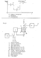
- Fig. 1 shows such a picture with some typical substances, where curve A is hydrogen, curve B is methane, curve C is carbon monoxide. If these results are evaluated in a microprocessor, to which the assignment of the sensor output signals and the temperature is transmitted, a three-dimensional matrix results, which is shown in FIG. 2.
- A is the sensor output signal
- B the sensor temperature and C a correction factor in order to be able to dimension the sensor output signal for specific substances, e.g. B. in ppm.
- each substance is "taken a fingerprint once" and stored as a number in the computer program. With the help of this method, numerous substances can be clearly identified.
- the device including the sensor is advantageously calibrated once with measuring gases, the specific correction numbers and identification numbers being stored in a non-volatile memory of the device. This process, which can be called “self-learning calibration and identification”, is advantageously carried out before the device is delivered to the customer.
- a semiconductor sensor element is connected in series with a resistor and forms an electrical voltage divider (1).
- the sensor element is heated by a heating device (3) which is fed by a controlled current source (2).
- the power source is program controlled by a microprocessor (7).
- the temperature (13) and the relative humidity (14) are read into the microprocessor (7) via an analog / digital converter (4) using suitable, technically known sensors. These can be shown on a display (8), the quantity and the quality of the detected substance being shown according to the invention.
- a protocol interface is provided, which is designed as a conventional computer interface.
- An alarm output (10) is provided in order to give an acoustic and / or visual alarm if freely defined danger values are exceeded.
- a keyboard is temporarily connected via a suitable, technically known interface, in order to be able to control the "learning process” and to define the group of substances that will later be shown in the display.
- the resulting identification and correction data are stored in a non-volatile memory (6), e.g. B. an EEPROM.
- the functionality of the battery can be checked via a test switch (12) and other relevant functions can be checked automatically.
- this device thus represents an inexpensive, easy-to-use and robust device which is not only able to detect the presence of any substances, but at the same time can make a statement as to which group of substances the substance is to be assigned and which concentration is present.
- the disadvantage is that at relatively low working temperatures, as are typical for some substances, the regeneration after exposure to the substances in particular is sometimes impermissibly long.
- the sensor temperature is periodically brought to a relatively high level, which, however, does not destroy the sensor element. During this period, the sensor element surface is reoxidized by reaction with the atmospheric oxygen. After this period, the sensor element temperature is brought to a level that corresponds to the highest sensitivity to a certain substance.
- the output value of the sensor cannot yet be used for measurement purposes because an equilibrium state must first be reached on the surface. After reaching equilibrium, measurements can be carried out in a stable and reproducible manner.
- the duration of the preparation phase T1 and the measurement phase T2 depend on the respective sensor type and on the conditions under which the sensor is used.
- the measured gas-dependent voltage (5) hereinafter referred to as sensor voltage, determined according to one of the previously described methods, is supplied to suitable evaluation electronics (13) which trigger an output signal (14).
- the energy required to operate the heating element (11) is made available by a control module (6).
- the heating power is solely a function of the heating voltage or the heating current, without a real control loop being created by temperature comparison.
- a reference value can be supplied via input (7), which influences the heating power / heating voltage. If the sensor element is operated under changing ambient temperatures, it makes sense to record the real sensor element temperature and process it as the actual variable in the controller (6).
- Switching takes place either manually and once or automatically and time-controlled by a time clock (15).
- this temperature is relatively low, e.g. B. 250 C.
- the sensor element requires an extremely long time after the disappearance of the oxidizable substance, in the example carbon monoxide, in order to form tin dioxide again with the atmospheric oxygen.
- the recovery behavior of the sensor element becomes extremely sluggish at low sensor temperatures, so that the measurement results cannot be used for a long time.
- the sensor element is operated at a temperature T 1 at which an optimal reaction with the atmospheric oxygen takes place.
- T 1 A defined initial state is achieved by oxidation of the sensor element surface.
- the heating temperature is switched to a lower temperature T 2, which corresponds to the optimum reaction temperature of the substance sought.
- the measured value (14) can be obtained and processed.
- a switch is made to a higher regeneration phase T 3 (heating phase), which can be equal to or higher than T 1.
- the sensor element is advantageously operated in the measuring phase in a temperature range in which it is particularly sensitive to very specific gases.
- the regeneration of the sensor element is accelerated by the periodic operation at temperatures at which the regeneration or oxidation of the sensor element surface takes place particularly quickly.
- a set specific sensitivity is therefore advantageously achieved quickly without the sensor element having to recover particularly slowly.
- metal oxide gas sensors have a significantly different sensitivity to specific gases at different temperatures.
- the explanation for this is that at certain temperatures the reactivity of the metal oxide and in this respect the readiness for oxidation of the specific gas is, among other things, a function of the surface temperature of the metal oxide.
- the solution takes advantage of the fact that the electrical resistance of a heating element is generally temperature-dependent, the majority of which has a positive temperature coefficient.
- Fig. 6 z. B the typical behavior of a platinum heater is shown, the electrical resistance of the heating element increases with increasing temperature of the heating element.
- the function between temperature and resistance can be defined.
- the temperature of the heating element is directly related to the temperature of the sensor element.
- the solution according to the invention consists in achieving reproducible temperature stabilization in that the heating resistance relevant to the desired temperature of the sensor is found and maintained.
- the teaching of the invention is therefore to design the heating of the sensor element so that the electrical resistance of the heating element serves as the actual variable.
- FIG. 7 A variant approaching the solution according to the invention is described in FIG. 7.
- the sensor element (3) is heated by a heating element (2), the thermal coupling between the heating element and the sensor element being very tight, so that both temperatures are almost identical.
- the power supply takes place e.g. B. from a controlled constant current source (1).
- the heating voltage (5) resulting from the current at the heating element is fed to a controller, which is preferably represented by a microprocessor (6).
- the microprocessor controller receives the desired size either program-controlled or set externally via a preselection device (7).
- the microprocessor controller (6) controls a constant voltage source (10).
- This voltage source drives a current through the heating element (2) and through a series resistor (9).
- a voltage (8) is tapped at the series resistor, which corresponds to the current due to the known laws.
- the current through the resistor (9) is inevitably identical to the current through the heating element (2).
- the total resistance flowing through the heating element (2) and the resistor (9) can easily be calculated.
- the known resistance value (9) the size of the ohmic resistance of the heating element (2) is calculated.
- the further embodiment corresponds to the teaching described above. It is important that the heating power is based on a predetermined resistance value of the heating element (2), the temperature-dependent values of which are used as the target value.
- a heating structure is applied to the ceramic substrate, which is preferably metallic.
- the object of the solution described below is to simplify the manufacturing process and to significantly reduce the tolerances by using processes known per se in semiconductor technology.
- the sensor carrier is made of silicon. Through the use of polycrystalline silicon, it is easily possible to form any desired shape and size of an ohmic heater with this carrier material.
- polycrystalline silicon When using polycrystalline silicon and appropriate contacting, it is possible to add a non-metallic electrical conductor to the carrier as a heater.
- a non-metallic electrical conductor As is known, polycrystalline silicon is electrically conductive and therefore heats up when a voltage is applied.
- FIGS. 9 and 10 show a heating element (1) which is electrically connected via the contacts (2) and operated via the voltage supply (3).
- This heating element (1) is now further processed according to the methods known in semiconductor technology and first receives an insulation layer (4) made of z. B. silicon dioxide.
- the thin-film elements are supported by a silicon substrate (5).
- a photosensitive layer is now applied, which contains the structures of the actual sensor element. Any desired structural shape can be produced.
- the senor base material After exposure, the sensor base material is applied. It is obvious that the accuracies that can be achieved with this method are considerably superior to those of conventional thick-film technology and therefore produce more uniform results.
- this process can be repeated any number of times, with different sensor materials being applied in the individual work steps, so that, for. B. the sensor elements (6), (7), (8).
- a temperature sensor element (9) can be applied at a location representative of the temperature, which is made of an electrically conductive and highly temperature-resistant material, e.g. B. made of platinum.
- FIG. 9 shows the basic structure in a sectional view
- FIG. 10 shows the basic structure in plan view.
- a catalyst layer made of a catalytically active metal such as. B. vaporize palladium, platinum, rodium, etc., or to apply in a suitable form, this layer being made gas-permeable.
- the applied layer is so thin that gas atoms can easily diffuse through it. It is also proposed that the catalyst layer be porous, e.g. B. in the form of a network structure.
- each individual sensor element being specifically sensitive to different gases.
- the sensitivity to individual gases can be significantly increased or even selectivity achieved by using suitable evaluation methods.
- heated sensor elements made of metal oxides or similar materials change their internal resistance when oxidizable or reducing gases are present.
- Usual evaluation circuits therefore work with a voltage divider, which is formed from an ohmic resistor and the sensor.
- the divider voltage resulting in the voltage divider is a function of the gas concentration.
- the senor is not flowed through with direct current, but with alternating voltage.
- Fig. 12 shows a diagram which shows the dependence of the sensor resistance for a given gas concentration on the frequency. Since the differences in the individual gases are significant, it is proposed to use this effect to increase the selectivity.
- the temperature is permanently changed between a maximum and minimum temperature by a computer for evaluation.
- the resulting data is saved and used to identify the gas.
- the sensor voltage typically changes with the frequency for certain gases.
- the sensor voltage is therefore read in by the microprocessor and stored during the learning process in a matrix which is located in the memory module (9 FIG. 11).
- the program of the microprocessor is written in such a way that the resulting sensitivity curves are always compared with the "learned" curves during later normal operation. In this respect, it is possible not only to make the sensor sensitive to certain gases by setting it to a certain frequency, but also to once again identify "learned" gases.
- the senor with a semiconductor sensor element which is applied to an electrically and thermally insulating support and is heated to an operating temperature by means of an electrical heater, is constructed in such a way that the semiconductor sensor element itself is designed as a heater.
- the advantageous integration of the heater in the semiconductor sensor element means that the previous separate heater can be dispensed with, so that the sensor as a whole can be manufactured much more cost-effectively.
- the desired operating temperature is kept constant in a simple manner, in order to use the reaction heat or temperature difference or change in conductivity of the sensor element as a measured variable for the gases to be detected when reacting with the gases surrounding the sensor.
- an evaluation unit is connected between the sensor element and the power controller via a circuit branch, which can be designed as a microprocessor.
- FIG. 13 shows a sensor with a power controller, an evaluation unit and a sensor element
- FIG. 16 shows a sectional illustration of the sensor element according to FIG. 14.
- the sensor element (14) shown in FIGS. 15 and 16 consists of a carrier 18 which, for. B. consists of an oxide ceramic 8, for example made of A1 2 0 3 or polycrystalline silicon with an electrically neutral insulating cover layer made of Si0 2 , on which a sensor element (14) designed as a semiconductor (32) is applied.
- the semiconductor (32) can, for example, be sintered onto the carrier. Another production possibility would be to apply the semiconductor (32) to the surface of the carrier (18) using thick-film technology.
- the semiconductor (32) consists of catalytically admixed and electrically conductive metal oxide, tin dioxide (Sn0 2 ) being used in an advantageous manner.
- the power regulator (12) shown in FIG. 13 and the sensor element (14) are connected to a current source (22) via the electrical connections (20) and (28).
- the power controller (12) is also connected to the sensor element (14) via an electrical connection (24) (16) to the electrical connection (24) and thus to the power controller and the sensor element (14).
- the gases can be detected in a simple manner.
- a voltage is applied to the sensor element (14), so that the current flow caused thereby inevitably results in the sensor element (14) being heated.
- the heating depends on the resistance of the sensor element (14) and on the applied voltage.
- the converted power is calculated with the heating voltage using the formulas
- the heating voltage U must therefore change as a function of the resistance R of the sensor element (14) and thus as a function of the gases surrounding the sensor element (14) so that the heating power P becomes constant. If the heating power P were not regulated, the heating power P would change depending on the resistance R.
- the power regulator (12) ensures that the product of current I and voltage U, that is to say the electrical power P, remains constant.
- the electrical power P is converted in the sensor element (14).
- the necessary voltage U applied to the sensor element (14) is constantly adapted by the power controller (12), the voltage U regularly decreasing when the sensor resistance R becomes smaller due to the presence of a gas and the power controller (12) reacts accordingly. It follows that the sensor voltage at the sensor element is a function of the gas concentration and can be evaluated in the evaluation unit (16).
- the power controller can be designed as a separate assembly. It is particularly advantageous if the power control is carried out by a microprocessor simultaneously with the signal evaluation, the microprocessor, which can be integrated in the evaluation unit (16), only has to measure the current. A further microprocessor is provided in the power controller (12), which processes the corresponding disturbance variables and ensures that the product of voltage U and current I, that is to say the power P, is kept constant.
- the power regulator (12) can also be designed as a controlled constant current source.
- the evaluation unit (16) which controls the constant current source via the connection (30).
Abstract
Description
Im Bereich der Umwelttechnik sind zunehmend Apparate und Vorrichtungen bestimmend, die das Vorhandensein von gasförmigen Verbindungen detektieren. Es wird dabei verlangt, daß diese Vorrichtungen möglichst in Echtzeit arbeiten, eine sehr hohe Verfügbarkeit und Lebensdauer haben und preislich deutlich niedriger als die bekannten Analyse-Geräte sind, um so eine massenhafte Verbreitung zu gestatten.In the field of environmental technology, devices and devices that detect the presence of gaseous compounds are becoming increasingly important. It is required that these devices work as much as possible in real time, have a very high availability and lifespan and are significantly lower in price than the known analysis devices, so as to permit mass distribution.
Es sind Sensoren für gasförmige Substanzen bekannt, die nach dem Prinzip der Brennstoffzelle arbeiten. Diese Sensoren arbeiten selektiy, gestatten also nicht nur den quantitativen Nachweis, sondern indirekt auch eine qualitative Zuordnung. Weiter sind Zinndioxid-Halbleitersensoren bekannt. Diese Sensoren detektieren alle oxidierbaren und reduzierenden Sustanzen. Dabei ist die spezifische Empfindlichkeit dieser Sensoren den einzelnen Substanzen gegenüber zwar unterschiedlich, der Erfassungsbereich ist allerdings so weit, daß man von Breitbandsensoren spricht. Diese Sensoren können im Bereich ab 0,1 ppm bei verschiedenen Substanzen erfolgreich eingesetzt werden, wenn die Quereinflüsse von Temperatur und relativer Feuchte kompensiert werden. Das Ausgangssignal des Sensors ist kein Meßwert, sondern lediglich ein Maßstab für das Vorhandensein irgendwelcher Substanzen, auf die der Sensor reagiert, wobei der Sensor summierende Eigenschaften hat.Sensors for gaseous substances are known which operate on the principle of the fuel cell. These sensors work selectively, so they not only allow quantitative detection, but indirectly also a qualitative assignment. Tin dioxide semiconductor sensors are also known. These sensors detect all oxidizable and reducing substances. The specific sensitivity of these sensors to the individual substances is different, but the detection range is so wide that one speaks of broadband sensors. These sensors can be used successfully with various substances in the range from 0.1 ppm if the cross influences of temperature and relative humidity are compensated. The output signal of the sensor is not a measured value, but merely a measure of the presence of any substances to which the sensor reacts, the sensor having summing properties.
Die hier beschriebene Erfindung hat sich zur Aufgabe gestellt, auf der Basis dieser preiswerten und robusten Sensoren eine qualifizierte Vorrichtung zu schaffen, die vorteilhaft einerseits eine Zuordnung der detektierten Substanz in einer Substanzklasse gestattet, ferner eine Aussage über die Größenordnung ihrer Konzentration gestattet.The object of the invention described here is to create a qualified device on the basis of these inexpensive and robust sensors, which advantageously allows assignment of the detected substance to a substance class on the one hand, and also permits a statement about the magnitude of its concentration.
Dabei macht sich die Erfindung die Tatsache zu eigen, daß in Abhängigkeit von zahlreichen Parametern die spektrale Empfindlichkeit einzelner Substanzen von Sensor zu Sensor höchst unterschiedlich ist.The invention adopts the fact that, depending on numerous parameters, the spectral sensitivity of individual substances varies greatly from sensor to sensor.
So ist es beispielsweise auch möglich, durch Verändern der Heizleistung und damit der Oberflächentemperatur des Sensorelementes die Reaktivität der Sensoroberfläche gegenüber verschiedenen Substanzen zu verändern.For example, it is also possible to change the reactivity of the sensor surface towards different substances by changing the heating power and thus the surface temperature of the sensor element.
So ist z. B. die Empfindlichkeit gegenüber Wasserstoff (H2) bereits bei sehr niedrigen Temperaturen sehr hoch. Dies gilt entsprechend für Substanzen mit vergleichbarer Affinität zu Sn02.So z. B. the sensitivity to hydrogen (H 2 ) is very high even at very low temperatures. This applies accordingly to substances with a comparable affinity for Sn0 2 .
Wenig reaktive Substanzen, z. B. Kohlenmonoxid, bedürfen einer relativ hohen Oberflächentemperatur des Sensorelementes.Little reactive substances, e.g. B. carbon monoxide, require a relatively high surface temperature of the sensor element.
Vereinfacht gesagt ist die Empfindlichkeit gegenüber bestimmten Substanzen bei bestimmten Temperaturen jeweils am höchsten.Simply put, sensitivity to certain substances is highest at certain temperatures.
Die Erfindung macht sich diese Eigenschaft wie folgt zu Nutze:
- Beispielsweise ist der Luft Kohlenmonoxid beigegeben, und dieses Gemisch wird auf 2 Sensoren geleitet. Der erste Sensor arbeitet mit geringer Oberflächentemperatur, während der zweite Sensor mit hoher Oberflächentemperatur betrieben wird. Ergebnismäßig wird es so sein, daß
Sensor 1 nur sehr geringen Werte anzeigt,Sensor 2 dagegen ein hohes Ausgangssignal erzeugt. Es ist gesichert, daß diese signifikanten Unterschiede typisch und reproduzierbar sind.
- For example, carbon monoxide is added to the air and this mixture is directed to two sensors. The first sensor works with a low surface temperature, while the second sensor operates with a high surface temperature. As a result,
sensor 1 will only display very low values, whereassensor 2 will produce a high output signal. It is certain that these significant differences are typical and reproducible.
In der Praxis wird regelmäßig Wert darauf gelegt, die in der Anwendersituation erwarteten spezifischen Substanzen aufzufinden, in Qualität und Quantität zu erkennen und entsprechende Warnungen auszugeben. So interessieren z. B. im Bergbau die Substanzen Kohlenmonoxid und Methan, beim Auskoffern kontaminierter Böden dagegen Benzol.In practice, regular emphasis is placed on finding the specific substances expected in the user situation, recognizing them in quality and quantity and issuing appropriate warnings. So interested z. B. in mining, the substances carbon monoxide and methane, but when extracting contaminated soils, benzene.
Da aufgrund der geringen Masse des Sensors die Oberflächentemperatur sehr rasch auf eine Veränderung der Heizleistung reagiert, ist es sehr leicht möglich, programmgesteuert die Heizleistung kontinuierlich zwischen einem Minimum- und Maximum-Wert zu verändern. Gleichzeitig wird das Ausgangssignal des Sensors beobach tet. Je nach Qualität der anwesenden Substanz wird bei Korrelation der Temperatur und des Sensorausgangssignals an einer bestimmten Position der Temperaturskala ein Maximum zu beobachten sein. Fig. 1 zeigt eine solche Aufnahme mit einigen typischen Substanzen, wobei Kurve A Wasserstoff ist, Kurve B Methan ist, Kurve C Kohlenmonoxid ist. Wertet man diese Ergebnisse in einem Mikroprozessor aus, dem die Zuordnung der Sensorausgangssignale und der Temperatur übertragen wird, ergibt sich eine dreidimensionale Matrix, die in Fig. 2 gezeigt wird. A ist dabei das Sensorausgangssignal, B die Sensortemperatur und C ein Korrekturfaktor, um bei spezifischen Substanzen das Sensorausgangssignal dimensionieren zu können, z. B. in ppm.Since the low temperature of the sensor means that the surface temperature reacts very quickly to a change in the heating output, it is very easy to program-continuously change the heating output between a minimum and a maximum value. At the same time, the output signal of the sensor is observed. Depending on the quality of the substance present, a maximum can be observed when the temperature and the sensor output signal are correlated at a specific position on the temperature scale. Fig. 1 shows such a picture with some typical substances, where curve A is hydrogen, curve B is methane, curve C is carbon monoxide. If these results are evaluated in a microprocessor, to which the assignment of the sensor output signals and the temperature is transmitted, a three-dimensional matrix results, which is shown in FIG. 2. A is the sensor output signal, B the sensor temperature and C a correction factor in order to be able to dimension the sensor output signal for specific substances, e.g. B. in ppm.
Aus dem Vorhergesagten ergibt sich, daß sich beim Durchfahren des Temperaturbereiches und bei Vorhandensein einer bestimmten Substanz eine spezifische Sensorsignalkurve ergibt, die typisch für die spezifische Substanz ist und die sich signifikant von anderen Substanzen unterscheidet. Innerhalb des Mikroprozessors sollen die Pegel an einzelnen Temperaturpunkten untereinander bewertet werden. Diese Bewertung ergibt rechnerisch eine typische Größe, die die Identifikation der Substanz erlaubt.It follows from the foregoing that when passing through the temperature range and when a certain substance is present, a specific sensor signal curve results which is typical of the specific substance and which differs significantly from other substances. Within the microprocessor, the levels at individual temperature points are to be evaluated with one another. This evaluation arithmetically results in a typical quantity, the identification of the substance allowed.
Vereinfacht gesagt, wird somit jeder Substanz "ein Fingerabdruck einmal abgenommen", und als Zahl im Rechenprogramm gespeichert. Mit Hilfe dieser Methode sind zahlreiche Substanzen eindeutig identifizierbar.Put simply, each substance is "taken a fingerprint once" and stored as a number in the computer program. With the help of this method, numerous substances can be clearly identified.
Da jede Substanz eine spezifische Affinität zum Sensorelement hat, muß das Sensorausgangssignal mit einer Korrekturzahl, die für die Substanz jeweils typisch ist multipliziert werden. Ergebnismäßig ist die erfindungsgemäße Vorrichtung also in der Lage
- 1. die unbekannte Substanz grob zu identifizieren,
- 2. die Konzentration in verkehrsüblichen Dimensionen innerhalb relativ kleiner Toleranzen anzugeben.
- 1. roughly identify the unknown substance,
- 2. Specify the concentration in traffic-usual dimensions within relatively small tolerances.
Vorteilhaft ist, daß dazu nur ein einziger Sensor benötigt wird, der als Halbleitersensor relativ preiswert ist und über eine sehr hohe Standzeit verfügt.It is advantageous that only a single sensor is required for this, which is relatively inexpensive as a semiconductor sensor and has a very long service life.
Vorteilhaft wird die Vorrichtung incl. Sensor einmal mit Meßgasen kalibriert, wobei die spezifischen Korrekturzahlen und Identifikationszahlen in einem nicht flüchtigen Speicher des Gerätes abgelegt werden. Diesen Vorgang, den man als "selbstlernende Kalibrierung und Identifizierung" bezeichnen kann, wird vorteilhaft vor Auslieferung des Gerätes an den Kunden durchführt.The device including the sensor is advantageously calibrated once with measuring gases, the specific correction numbers and identification numbers being stored in a non-volatile memory of the device. This process, which can be called "self-learning calibration and identification", is advantageously carried out before the device is delivered to the customer.
Diese Vorrichtung wird anhand der Fig. 3 erläutert.This device is explained with reference to FIG. 3.
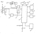
Ein Halbleitersensorelement ist mit einem Widerstand in Reihe geschaltet und bildet einen elektrischen Spannungsteiler (1). Das Sensorelement wird dabei über eine Heizeinrichtung (3) beheizt, die über eine gesteuerte Stromquelle (2) gespeist wird. Die Stromquelle wird von einem Mikroprozessor (7) programmgesteuert. Zusätzlich werden über geeignete, technisch bekannte Sensoren die Temperatur (13) und die relative Feuchte (14) über einen Analog/Digital-Wandler (4) in den Mikroprozessor (7) eingelesen. Diese können auf einem Display (Anzeige) (8) angezeigt werden, wobei erfindungsgemäß die Quantität als auch die Qualität der detektierten Substanz angezeigt werden. Vorgesehen ist eine Protokoll-Schnittstelle, die als übliche Computer-Schnittstelle ausgelegt ist. Ein Alarmausgang (10) ist vorgesehen, um bei Überschreiten frei festgelegter Gefahrenwerte akustischen und/oder optischen Alarm zu geben. Während des "Lernvorgangs" ist über eine geeignete, technisch bekannte Schnittstelle eine Tastatur vorübergehend angeschlossen, um den "Lernvorgang" steuern zu können und um die Stoffgruppe, die im Display (Anzeige) später angezeigt werden soll, zu definieren. Die dabei anfallenden Identifikations- und Korrekturdaten werden in einem nicht flüchtigen Speicher (6), z. B. einem EEPROM, abgelegt. Über einen Testschalter (12) kann die Funktionsfähigkeit der Batterie geprüft werden und weitere relevante Funktionen können automatisch geprüft werden.A semiconductor sensor element is connected in series with a resistor and forms an electrical voltage divider (1). The sensor element is heated by a heating device (3) which is fed by a controlled current source (2). The power source is program controlled by a microprocessor (7). In addition, the temperature (13) and the relative humidity (14) are read into the microprocessor (7) via an analog / digital converter (4) using suitable, technically known sensors. These can be shown on a display (8), the quantity and the quality of the detected substance being shown according to the invention. A protocol interface is provided, which is designed as a conventional computer interface. An alarm output (10) is provided in order to give an acoustic and / or visual alarm if freely defined danger values are exceeded. During the "learning process", a keyboard is temporarily connected via a suitable, technically known interface, in order to be able to control the "learning process" and to define the group of substances that will later be shown in the display. The resulting identification and correction data are stored in a non-volatile memory (6), e.g. B. an EEPROM. The functionality of the battery can be checked via a test switch (12) and other relevant functions can be checked automatically.
Vorteilhaft stellt diese erfindungsgemäße Vorrichtung damit ein preiswertes, einfach zu bedienendes und robustes Gerät vor, das nicht nur das Vorhandensein irgendwelcher Substanzen zu detektieren in der Lage ist, sondern gleichzeitig eine Aussage machen kann, welcher Stoffgruppe die Substanz zuzuordnen ist und welche Konzentration vorliegt.Advantageously, this device according to the invention thus represents an inexpensive, easy-to-use and robust device which is not only able to detect the presence of any substances, but at the same time can make a statement as to which group of substances the substance is to be assigned and which concentration is present.
Weiterhin ist bekannt, daß oxidierbare und reduzierbare Gase eine Leitwertänderung an der Oberfläche von Metalloxyden bewirken, weil die Substanzen mit dem im Metalloxid gebundenen Sauerstoff reagieren. Um die Reaktionsfreudigkeit zu erhöhen und um den Prozeß reversibel zu machen, wird bei einschlägigen Sensoren der Metalloxid-Leiter beheizt.It is also known that oxidizable and reducible gases cause a change in the conductance on the surface of metal oxides because the substances react with the oxygen bound in the metal oxide. In order to increase the reactivity and to make the process reversible, the metal oxide conductor is heated in relevant sensors.
Mit unterschiedlichen Dotierungen wird bekanntlich erreicht, daß die Sensitivität des Sensorelementes verschiedenen Substanzen gegenüber unterschiedlich wird. Weiter ist bekannt, daß die Empfindlichkeit gegenüber bestimmten Substanzen auch eine Frage der Oberflächentemperatur des Sensorelementes ist.With different doping it is known that the sensitivity of the sensor element to different substances is different. It is also known that sensitivity to certain substances is also a question of the surface temperature of the sensor element.
Aus diesem Grunde ist eingangs vorgeschlagen worden, die Temperatur periodisch zu ändern und aus der temperaturabhängigen Verteilung der Ausgangssignalamplituden auf die einwirkende Substanz zu schließen. Wenn eine bestimmte Substanz detektiert werden soll, liegt es nahe, das Sensorelement auf denjenigen Temperaturpunkt einzustellen, der der höchsten Empfindlichkeit der Substanz gegenüber entspricht.For this reason, it was initially proposed to change the temperature periodically and to infer the substance acting from the temperature-dependent distribution of the output signal amplitudes. If a certain substance is to be detected, it makes sense to set the sensor element to the temperature point that corresponds to the highest sensitivity of the substance.
Wenn durch geeignete Schaltungsmaßnahmen, wie nachstehend vorgeschlagen, dieser Temperaturpunkt exakt eingehalten wird, kann mit dieser Methode die Querempfindlichkeit anderen Substanzen gegenüber gemindert werden.If, by means of suitable circuit measures, as suggested below, this temperature point is exactly maintained, the cross-sensitivity to other substances can be reduced with this method.
Nachteilig ist, daß bei relativ niedrigen Arbeitstemperaturen, wie sie für manche Substanzen typisch sind, insbesondere die Regeneration nach Einwirken der Substanzen teilweise unzulässig lang ist.The disadvantage is that at relatively low working temperatures, as are typical for some substances, the regeneration after exposure to the substances in particular is sometimes impermissibly long.
Es wird daher gemäß Anspruch 4 vorgeschlagen, die Oberflächentemperatur des Sensorelementes zu verändern.It is therefore proposed according to
Dabei wird periodisch die Sensortemperatur auf ein relativ hohes Niveau gebracht, welches das Sensorelement jedoch nicht zerstört. In dieser Zeitspanne wird die Sensorelementoberfläche durch Reaktion mit dem Luftsauerstoff reoxidiert. Nach Ablauf dieser Zeit spanne wird die Sensorelementtemperatur gezielt auf ein Niveau gebracht, die der höchsten Sensitivität gegenüber einer bestimmten Substanz entspricht.The sensor temperature is periodically brought to a relatively high level, which, however, does not destroy the sensor element. During this period, the sensor element surface is reoxidized by reaction with the atmospheric oxygen. After this period, the sensor element temperature is brought to a level that corresponds to the highest sensitivity to a certain substance.
Es ist schaltungstechnisch also erforderlich, diese Temperatur, die man auch als optimale Reaktionstemperatur bezeichnen könnten, einstellbar zu gestalten.In terms of circuitry, it is therefore necessary to make this temperature adjustable, which could also be called the optimal reaction temperature.
Unmittelbar nach dem Sprung auf das Reaktionstemperatur-Niveau kann der Ausgangswert des Sensors noch nicht für Meßzwecke herangezogen werden, weil erst ein Gleichgewichtszustand an der Oberfläche erreicht werden muß. Nach Erreichen des Gleichgewichtszustandes kann stabil und reproduzierbar gemessen werden.Immediately after the jump to the reaction temperature level, the output value of the sensor cannot yet be used for measurement purposes because an equilibrium state must first be reached on the surface. After reaching equilibrium, measurements can be carried out in a stable and reproducible manner.
Die Dauer der Vorbereitungsphase T1 und der Meßphase T2 hängen vom jeweiligen Sensortyp ab und von den Bedingungen, unter denen der Sensor eingesetzt wird.The duration of the preparation phase T1 and the measurement phase T2 depend on the respective sensor type and on the conditions under which the sensor is used.
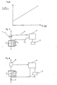
Diese erfindungsmäßige Lösung wird daher wie folgt anhand der Fig. 4 und 5 beschrieben:
- Das Sensorelement besteht in der Regel aus einer Heizung (11), die wärmeleitend mit dem Metalloxid-Widerstand (12) verbunden ist. Erfindungsgemäß wird vorgeschlagen, ebenfalls ein temperaturabhängiges Widerstandselement (10) wärmeleitend mit dem Heizelement (11) zu verbinden. Die Leitfähigkeit des Metalloxid-Widerstandes (12) ist in einem Spannungsteiler oder einer Brükkenschaltung so anzuordnen, daß sich ergebnismäßig eine Spannung (5) ergibt, die abhängig vom Meßgas ist. Heizelement. Metalloxid-Widerstand und temperaturabhängiger Widerstand können in einem Gehäuse zusammengefaßt werden. Sie werden im folgenden Sensorelement genannt.
- The sensor element usually consists of a heater (11) which is thermally connected to the metal oxide resistor (12). According to the invention, a temperature-dependent resistance element (10) is also connected in a heat-conducting manner to the heating element (11). The conductivity of the metal oxide resistor (12) should be arranged in a voltage divider or a bridge circuit so that the result is a voltage (5) which is dependent on the sample gas. Heating element. Metal oxide resistance and temperature-dependent resistance can be combined in one housing. They are called sensor element in the following.
Die nach einer der vorherbeschriebenen Methoden ermittelte meßgasabhängige Spannung (5), im folgenden Sensorspanung genannt, wird einer geeigneten Auswertelektronik (13) zugeführt, die ein Ausgangssignal (14) veranlaßt.The measured gas-dependent voltage (5), hereinafter referred to as sensor voltage, determined according to one of the previously described methods, is supplied to suitable evaluation electronics (13) which trigger an output signal (14).
Die für den Betrieb des Heizelementes (11) erforderliche Energie wird von einem Regelbaustein (6) zur Verfügung gestellt. Im einfachsten Fall ist die Heizleistung allein eine Funktion der Heizspannung oder des Heizstroms, ohne daß es zu einem echten Regelkreis durch Temperaturvergleich kommt. In diesem Fall kann über den Eingang (7) ein Referenzwert zugeführt werden, der auf die Heizleistung/Heizspannung Einfluß hat. Wird das Sensorelement unter wechselnden Umgebungstemperaturen betrieben, ist es sinnvoll, die echte Sensorelementtemperatur zu erfassen und als Ist-Größe im Regler (6) zu verarbeiten.The energy required to operate the heating element (11) is made available by a control module (6). In the simplest case, the heating power is solely a function of the heating voltage or the heating current, without a real control loop being created by temperature comparison. In this case, a reference value can be supplied via input (7), which influences the heating power / heating voltage. If the sensor element is operated under changing ambient temperatures, it makes sense to record the real sensor element temperature and process it as the actual variable in the controller (6).
Um das erfindungsgemäße Verfahren durchführen zu können, wird vorgeschlagen, den Referenzwert umschaltbar oder steuerbar zu gestalten derart, daß er einen Wert 8, 9, 9a usw. annehmen kann.In order to be able to carry out the method according to the invention, it is proposed to make the reference value switchable or controllable in such a way that it can assume a
Die Umschaltung erfolgt entweder von Hand und einmalig oder automatisch und zeitgesteuert durch einen Zeittaktgeber (15).Switching takes place either manually and once or automatically and time-controlled by a time clock (15).
Im letzteren Fall gilt folgender Zusammenhang: In Luft reoxidiert die Oberfläche des Metalloxid-Sensorelementes z. B. zu reinem Zinndioxid (Sn02). In Verbindung mit dem Luftsauerstoff stellt sich nach kurzer Zeit ein stabiles Gleichgewicht ein. Unter Anwesenheit von oxidierbaren Gasen, z. B. CO (Kohlenmonoxid) wird an der Oberfläche des Sensorwiderstands Zinndioxid zu Zinnsuboxiden (Sn02, ) reduziert, wobei Sauerstoff-Atome das Kohlenmonoxid aufoxidieren. Diese Reaktion verläuft bei einer typischen Temperatur am effektivsten, so daß bei einer bestimmten, ermittelbaren Temperatur die spezifisch höchste Empfindlichkeit einem bestimmten Stoff gegenüber auftritt.In the latter case, the following relationship applies: In air, the surface of the metal oxide sensor element z. B. to pure tin dioxide (Sn0 2 ). In connection with atmospheric oxygen, a stable equilibrium is established after a short time. In the presence of oxidizable gases, e.g. B. CO (carbon monoxide) is reduced on the surface of the sensor resistor tin dioxide to tin suboxides (Sn02,), with oxygen atoms oxidizing the carbon monoxide. This reaction is most effective at a typical temperature, so that the specific highest sensitivity to a certain substance occurs at a certain, determinable temperature.
Bei einigen Stoffen ist diese Temperatur relativ niedrig, z. B. 250 C. Ist eine Reaktion, wie vorstehend beschrieben, eingetreten und z. B. Zinndioxid zu Suboxiden reduziert worden, benötigt nach Verschwinden der oxidierbaren Substanz, im Beispiel Kohlenmonoxid, das Sensorelement eine äußerst lange Zeit, um mit dem Luftsauerstoff wieder Zinndioxid zu bilden. Das Erholungsverhalten des Sensorelementes wird bei niedrigen Sensortemperaturen äußerst träge, so daß die Meßergebnisse lange Zeit nicht verwertbar sind. Erfindungsgemäß wird vorgeschlagen, die Heiztemperatur periodisch zu verändern. Bei Beginn jeder Messung und anschließend periodisch wird das Sensorelement mit einer Temperatur T 1 betrieben, bei der eine optimale Reaktion mit dem Luftsauerstoff stattfindet. Es wird ein definierter Ausgangszustand durch Oxidation der Sensorelementoberfläche erzielt. Nach Ablauf dieser Vorbereitungsphase T1 1 wird die Heiztemperatur umgeschaltet auf eine niedrigere Temperatur T 2, die der optimalen Reaktionstemperatur der gesuchten Substanz gegenüber entspricht. In dieser Zeit kann der Meßwert (14) gewonnen und verarbeitet werden.For some fabrics, this temperature is relatively low, e.g. B. 250 C. Has a reaction as described above occurred and e.g. B. tin dioxide has been reduced to suboxides, the sensor element requires an extremely long time after the disappearance of the oxidizable substance, in the example carbon monoxide, in order to form tin dioxide again with the atmospheric oxygen. The recovery behavior of the sensor element becomes extremely sluggish at low sensor temperatures, so that the measurement results cannot be used for a long time. According to the invention, it is proposed to change the heating temperature periodically. At the start of each measurement and then periodically, the sensor element is operated at a
Nach Ablauf dieser Phase, im nachfolgenden Meßphase genannt, wird auf eine höhere Regenerationsphase T 3 (Ausheizphase) geschaltet, die gleich oder höher als T 1 sein kann.After the end of this phase, hereinafter referred to as the measuring phase, a switch is made to a higher regeneration phase T 3 (heating phase), which can be equal to or higher than
Ergebnismäßig wird erreicht, daß in der Meßphase das Sensorelement vorteilhaft in einem Temperaturbereich betrieben wird, in dem er gegenüber ganz spezifischen Gasen besonders empfindlich ist. Die Regeneration des Sensorelementes wird beschleunigt durch den periodischen Betrieb mit Temperaturen, bei denen die Regeneration bzw. Oxidation der Sensorelementoberfläche besonders schnell abläuft.As a result, the sensor element is advantageously operated in the measuring phase in a temperature range in which it is particularly sensitive to very specific gases. The regeneration of the sensor element is accelerated by the periodic operation at temperatures at which the regeneration or oxidation of the sensor element surface takes place particularly quickly.
Vorteilhaft wird daher eine eingestellte spezifische Empfindlichkeit schnell erreicht, ohne daß sich das Sensorelement besonders träge erholen muß.A set specific sensitivity is therefore advantageously achieved quickly without the sensor element having to recover particularly slowly.
In Fällen, in denen permanente Einsatzbereitschaft und schnelle Reaktion zwingend erforderlich sind, wird erfindungsgemäß vorgeschlagen, zwei Sensoren antiparallel zu betreiben, so daß stets ein Meßsignal (5) verfügbar ist.In cases in which permanent operational readiness and rapid reaction are absolutely necessary, it is proposed according to the invention to operate two sensors antiparallel, so that always one Measurement signal (5) is available.
Ferner ist bekannt, daß Metalloxid-Gassensoren bei unterschiedlichen Temperaturen eine signifikant unterschiedliche Empfindlichkeit gegenüber spezifischen Gasen haben. Die Erklärung dafür ist, daß bei bestimmten Temperaturen die Reaktivität des Metalloxides und insofern die Oxidationsbereitschaft des spezifischen Gases unter anderem eine Funktion der Oberflächentemperatur des Metalloxides ist.It is also known that metal oxide gas sensors have a significantly different sensitivity to specific gases at different temperatures. The explanation for this is that at certain temperatures the reactivity of the metal oxide and in this respect the readiness for oxidation of the specific gas is, among other things, a function of the surface temperature of the metal oxide.
Oben ist daher beschrieben worden, wie mit Hilfe dieses Effektes die zu detektierenden Gase sowohl nach Qualität als auch nach Quantität bestimmt werden können.It has therefore been described above how this effect can be used to determine the gases to be detected both in terms of quality and in terms of quantity.
Dabei ist davon ausgegangen worden, daß es möglich ist, eine bestimmte Temperatur des Sensorelementes reproduzierbar zu erreichen. Es ist vorher vorgeschlagen worden, auf dem Sensorelement einen temperaturabhängigen Widerstand anzubringen, der repräsentativ die Temperatur der Sensorelementoberfläche wiedergibt.It has been assumed that it is possible to reproducibly reach a certain temperature of the sensor element. It has previously been proposed to mount a temperature-dependent resistor on the sensor element, which representatively represents the temperature of the sensor element surface.
Diese Lösung bedingt, daß spezielle Fertigungstechnologien eingesetzt werden müssen. Standardmäßig am Markt verfügbare Sensorelemente können nicht eingesetzt werden.This solution means that special manufacturing technologies have to be used. Sensor elements available on the market as standard cannot be used.
Daher soll eine Lösung gefunden werden, die es erlaubt, vorteilhaft auch am Markt erhältliche Sensorelemente für den vorstehend beschriebenen Zweck einsetzen zu können.A solution is therefore to be found which allows sensor elements which are available on the market to be used advantageously for the purpose described above.
Die Lösung macht sich die Tatsache zu nutze, daß der elektrische Widerstand eines Heizelementes in der Regel temperaturabhängig ist, wobei mehrheitlich ein positiver Temperaturkoeffizient zu beobachten ist. In Fig. 6 ist z. B. das typische Verhalten eines Platin-Heizers dargestellt, wobei mit zunehmender Temperatur des Heizelementes der elektrische Widerstand des Heizelementes steigt. In der Regel ist die Funktion zwischen Temperatur und Widerstand definierbar.The solution takes advantage of the fact that the electrical resistance of a heating element is generally temperature-dependent, the majority of which has a positive temperature coefficient. In Fig. 6 z. B. the typical behavior of a platinum heater is shown, the electrical resistance of the heating element increases with increasing temperature of the heating element. As a rule, the function between temperature and resistance can be defined.
Aufgrund der dichten thermischen Kopplung zwischen Heizelement und Sensorelement kann davon ausgegangen werden, daß die Temperatur des Heizelementes in einem direkten Zusammenhang mit der Temperatur des Sensorelementes steht.Due to the tight thermal coupling between the heating element and the sensor element, it can be assumed that the temperature of the heating element is directly related to the temperature of the sensor element.
Die erfindungsgemäße Lösung besteht darin, eine reproduzierbare Temperaturstabilisierung dadurch zu erreichen, daß der für die angestrebte Temperatur des Sensors relevante Heizungswiderstand aufgefunden und gehalten wird.The solution according to the invention consists in achieving reproducible temperature stabilization in that the heating resistance relevant to the desired temperature of the sensor is found and maintained.
Die Lehre der Erfindung besteht also darin, die Heizung des Sensorelementes so auszulegen, daß der elektrische Widerstand des Heizungselementes als Ist-Größe dient.The teaching of the invention is therefore to design the heating of the sensor element so that the electrical resistance of the heating element serves as the actual variable.
Eine der erfindungsgemäßen Lösung nahekommende Variante ist in Fig. 7 beschrieben. Das Sensorelement (3) wird durch ein Heizelement (2) beheizt, wobei die thermische Kopplung zwischen Heizelement und Sensorelement sehr eng ist, so daß beide Temperaturen nahezu identisch sind.A variant approaching the solution according to the invention is described in FIG. 7. The sensor element (3) is heated by a heating element (2), the thermal coupling between the heating element and the sensor element being very tight, so that both temperatures are almost identical.
Die Stromversorgung erfolgt z. B. aus einer gesteuerten Konstantstromquelle (1).The power supply takes place e.g. B. from a controlled constant current source (1).
Die sich durch den Strom am Heizelement ergebende Heizspannung (5) wird einem Regler zugeführt, der bevorzugt durch einen Mikroprozessor (6) dargestellt ist. Die Soll-Größe erhält der Mikroprozessor-Regler entweder programmgesteuert oder extern eingestellt über eine Vorwahleinrichtung (7).The heating voltage (5) resulting from the current at the heating element is fed to a controller, which is preferably represented by a microprocessor (6). The microprocessor controller receives the desired size either program-controlled or set externally via a preselection device (7).
Da die gewünschte Größe weder Strom, noch Spannung, sondern der Widerstand ist, errechnet der Mikroprozessor aus Spannung und Strom nach dem Ohmschen Gesetz R = U/I den Ohmschen Widerstand. Insofern erfolgt ein Soll/Ist-Vergleich anhand des eingegebenen Soll-Widerstandes und des ermittelten elektrischen Widerstandes des Heizers.Since the desired size is neither current nor voltage, but resistance, the microprocessor calculates the ohmic resistance from voltage and current according to Ohm's law R = U / I. In this respect, a target / actual comparison takes place on the basis of the entered target resistance and the determined electrical resistance of the heater.
In Fig. 8 ist beispielhaft eine weitere Ausführung beschrieben.Another embodiment is described by way of example in FIG. 8.
Dabei wird nicht der Strom, sondern die Spannung der Heizung variiert.It is not the current, but the voltage of the heating that is varied.
Der Mikroprozessor-Regler (6) steuert eine Konstantspannungsquelle (10). Diese Spannungsquelle treibt einen Strom durch das Heizelement (2) und durch einen Serienwiderstand (9). Am Serienwiderstand wird eine Spannung (8) abgegriffen, die aufgrund der bekannten Gesetzmäßigkeiten mit dem Strom korrespondiert. Zwangsläufig ist der Strom durch den Widerstand (9) identisch mit dem Strom durch das Heizelement (2). Mit Hilfe des bekannten Ohmschen Gesetzes kann leicht der Gesamtwiderstand errechnet werden, der durch das Heizelement (2) und den Widerstand (9) fließt. Unter Berücksichtigung des bekannten Widerstandswertes (9) errechnet sich die Größe des Ohmschen Widerstandes des Heizelementes (2).The microprocessor controller (6) controls a constant voltage source (10). This voltage source drives a current through the heating element (2) and through a series resistor (9). A voltage (8) is tapped at the series resistor, which corresponds to the current due to the known laws. The current through the resistor (9) is inevitably identical to the current through the heating element (2). With the help of the well-known Ohm's law, the total resistance flowing through the heating element (2) and the resistor (9) can easily be calculated. Taking into account the known resistance value (9), the size of the ohmic resistance of the heating element (2) is calculated.
Die weitere Ausgestaltungsweise entspricht der vorstehend beschriebenen Lehre. Wesentlich ist, das die Heizleistung sich an einem vorgegebenen Widerstandswert des Heizelementes (2) orientiert, dessen temperaturabhängige Werte als Soll-Wert herangezogen werden.The further embodiment corresponds to the teaching described above. It is important that the heating power is based on a predetermined resistance value of the heating element (2), the temperature-dependent values of which are used as the target value.
Insofern ist es vorteilhaft und einfach möglich, die Temperatur eines beheizten Halbleiter-Metalloxid-Gassensors über die Heizung kontrolliert und reproduzierbar zu regeln, ohne ein zusätzliches temperaturabhängiges Element in die Sensoranordnung integrieren zu müssen.In this respect, it is advantageous and easily possible to control and reproducibly control the temperature of a heated semiconductor metal oxide gas sensor via the heater without having to integrate an additional temperature-dependent element into the sensor arrangement.
Darüber hinaus ist es bekannt, daß verschiedene Substanzen, insbesondere Metalloxyde, z. B. Zinndioxid, den ohmschen Widerstand dann verändern, wenn gleichzeitig oxidierbare Gase, z. B. Kohlenmonoxid, vorhanden sind. Diesen Effekt machen sich zahlreiche am Markt angebotene Sensoren zunutze, wobei üblicherweise folgende Konstruktionselemente eingesetzt werden:
- Der Sensor selbst besteht aus einem gesinterten Zinndioxid oder einem Zinndioxid-Dickfilm, der auf einem keramischen Träger, vorzugsweise aus Aluminium aufgebracht ist. Mitunter ist der Keramik-Träger als Röhrchen ausgebildet, wobei in dem Röhrchen ein ohmscher Widerstand als Heizer angebracht wird, der die Oberfläche des Metalloxydes auf eine Temperatur zwischen 100 C und 500 ° C erwärmen kann.
- The sensor itself consists of a sintered tin dioxide or a tin dioxide thick film, which is applied to a ceramic carrier, preferably made of aluminum. Sometimes the ceramic carrier is designed as a tube, an ohmic resistor being attached as a heater in the tube, which can heat the surface of the metal oxide to a temperature between 100 ° C. and 500 ° C.
Bei anderen Konstruktionen ist auf dem Keramiksubstrat eine Heizstruktur aufgebracht, die vorzugsweise metallisch ist.In other constructions, a heating structure is applied to the ceramic substrate, which is preferably metallic.
Die Herstellungsprozesse für Sensoren dieser Art haben den Nachteil, daß Schichtdicke und Schichtgeometrie relativ große Toleranzen aufweisen, was bei der technischen Anwendung zu Problemen führt.The manufacturing processes for sensors of this type have the disadvantage that layer thickness and layer geometry have relatively large tolerances, which leads to problems in technical application.
Der nachstehend beschriebenen Lösung liegt die Aufgabe zugrunde, durch Einsatz von in der Halbleitertechnik an sich bekannten Verfahren den Herstellungsprozeß zu vereinfachen und die Toleranzen erheblich zu senken.The object of the solution described below is to simplify the manufacturing process and to significantly reduce the tolerances by using processes known per se in semiconductor technology.
Ähnlich wie bei Halbleiterchips besteht auch hier der Sensorträger aus Silizium. Durch den Einsatz polykristallinen Siliziums ist es bei diesem Trägermaterial ohne weiteres möglich, jede gewünschte Form und Größenordnung einer ohmschen Heizung auszubilden.Similar to semiconductor chips, the sensor carrier is made of silicon. Through the use of polycrystalline silicon, it is easily possible to form any desired shape and size of an ohmic heater with this carrier material.
Bei Verwendung von polykristallinem Silizium und entsprechender Kontaktierung, ist es möglich, dem Träger einen nichtmetallischen elektrischen Leiter als Heizer beizugeben. Denn bekanntlich ist polykristallines Silizium elektrisch leitfähig und erwärmt sich demnach beim Anlegen einer Spannung.When using polycrystalline silicon and appropriate contacting, it is possible to add a non-metallic electrical conductor to the carrier as a heater. As is known, polycrystalline silicon is electrically conductive and therefore heats up when a voltage is applied.
Die Fig. 9 und 10 zeigen ein Heizelement (1), was über die Kontaktierungen (2) elektrisch angeschlossen wird und über die Spannungsversorgung (3) betrieben wird. Dieses Heizelement (1) wird nunmehr nach den in der Halbleitertechnik bekannten Verfahren weiterverarbeitet und erhält zuerst eine Isolationsschicht (4) aus z. B. Siliziumdioxid. Träger der Dünnschichtelemente ist ein Siliziumsubstrat (5).9 and 10 show a heating element (1) which is electrically connected via the contacts (2) and operated via the voltage supply (3). This heating element (1) is now further processed according to the methods known in semiconductor technology and first receives an insulation layer (4) made of z. B. silicon dioxide. The thin-film elements are supported by a silicon substrate (5).
In verschiedenen Herstellungsschritten wird nunmehr eine photoempfindliche Schicht aufgebracht, die die Strukturen des eigentlichen Sensorelementes enthält. Dabei kann jede gewünschte Strukturform hergestellt werden.In various manufacturing steps, a photosensitive layer is now applied, which contains the structures of the actual sensor element. Any desired structural shape can be produced.
Nach dem Belichten wird der Sensorgrundstoff aufgebracht. Es liegt auf der Hand, daß die mit diesem Verfahren erreichbaren Genauigkeiten dem der herkömmlichen Dickschichttechnik erheblich überlegen sind und insofern gleichmäßigere Ergebnisse bringen.After exposure, the sensor base material is applied. It is obvious that the accuracies that can be achieved with this method are considerably superior to those of conventional thick-film technology and therefore produce more uniform results.
Im Prinzip kann dieser Vorgang beliebig oft wiederholt werden, wobei in den einzelnen Arbeitsschritten unterschiedliche Sensormaterialien aufgebracht werden, so daß sich z. B. die Sensorelemente (6), (7), (8) ergeben.In principle, this process can be repeated any number of times, with different sensor materials being applied in the individual work steps, so that, for. B. the sensor elements (6), (7), (8).
Wenn es notwendig ist, kann ein Temperatur-Sensorelement (9) an einem für die Temperatur repräsentativen Ort aufgebracht werden, das aus einem elektrisch leitenden und stark temperaturbeständigen Material besteht, z. B. aus Platin.If necessary, a temperature sensor element (9) can be applied at a location representative of the temperature, which is made of an electrically conductive and highly temperature-resistant material, e.g. B. made of platinum.
Die Fig. 9 zeigt den prinzipiellen Aufbau im Schnittbild, während Fig. 10 den prinzipiellen Aufbau in Draufsicht zeigt.FIG. 9 shows the basic structure in a sectional view, while FIG. 10 shows the basic structure in plan view.
Um die Sensoreigenschaften zu verändern, wird weiter vorgeschlagen, die Eigenschaften der Sensorelemente dadurch gezielt zu beeinflussen, in dem in einem weiteren Arbeitsschritt auf das Sensorelementmaterial eine weitere Schicht bzw. weitere Schichten aufgebracht werden. Insbesondere wird vorgeschlagen, eine Katalysatorschicht aus einem katalytisch wirkenden Metall, wie z. B. Paladium, Platin, Rodium etc. aufzudampfen bzw, in geeigneter Form aufzubringen, wobei diese Schicht gasdurchlässig gestaltet ist.In order to change the sensor properties, it is further proposed to specifically influence the properties of the sensor elements by applying a further layer or layers to the sensor element material in a further working step. In particular, it is proposed that a catalyst layer made of a catalytically active metal, such as. B. vaporize palladium, platinum, rodium, etc., or to apply in a suitable form, this layer being made gas-permeable.
Die letzte Forderung wird realisiert, in dem die aufgebrachte Schicht so dünn ist, daß Gasatome mühelos durch diese durchdiffundieren können. Auch wird vorgeschlagen, die Katalysatorschicht porös, z. B. in Form einer Netzstruktur, aufzubringen.The last requirement is realized in that the applied layer is so thin that gas atoms can easily diffuse through it. It is also proposed that the catalyst layer be porous, e.g. B. in the form of a network structure.
Wesentlich ist, daß erfindungsgemäß nicht nur die Geometrie und das Material des eigentichen Sensorelementes unterschiedlich sein kann, sondern auch die Katalysatorschicht.It is essential that according to the invention not only the geometry and the material of the actual sensor element can be different, but also the catalyst layer.
Damit ist es erfindungsgemäß möglich, sehr vorteilhaft auf einem Chip eine Gruppe von Sensoren aufzubauen, wobei jedes einzelne Sensorelement spezifisch empfindlich auf unterschiedliche Gase ist. Insofern kann durch geeignete Auswertemethoden die Empfindlichkeit gegenüber einzelnen Gasen erheblich gesteigert werden bzw. sogar Selektivität erreicht werden.It is thus possible according to the invention to very advantageously build up a group of sensors on a chip, each individual sensor element being specifically sensitive to different gases. In this respect, the sensitivity to individual gases can be significantly increased or even selectivity achieved by using suitable evaluation methods.
Wie vorstehend beschrieben, verändern beheizte Sensorelemente aus Metalloxiden oder ähnlichen Materialien ihren inneren Widerstand dann, wenn oxidierbare oder reduzierend wirkende Gase anwesend sind.As described above, heated sensor elements made of metal oxides or similar materials change their internal resistance when oxidizable or reducing gases are present.
Weiterhin ist bekannt, daß die Empfindlichkeit veschiedenen Gasen gegenüber bei bestimmten Temperaturen jeweils am größten ist.It is also known that the sensitivity to various gases is greatest at certain temperatures.
Übliche Auswerteschaltungen arbeiten daher mit einem Spannungsteiler, der aus einem ohmschen Widerstand und dem Sensor gebildet wird. Die sich im Spannungsteiler ergebene Teilerspannung ist eine Funktion der Gaskonzentration.Usual evaluation circuits therefore work with a voltage divider, which is formed from an ohmic resistor and the sensor. The divider voltage resulting in the voltage divider is a function of the gas concentration.
Nachstehend wird beschrieben, daß der Sensor nicht mit Gleichstrom durchflossen wird, sondern mit Wechselspannung.It is described below that the sensor is not flowed through with direct current, but with alternating voltage.
Bemerkenswert dabei ist die Tatsache, daß der mit verschiedenen Frequenzen ermittelte Sensorwiderstand nicht konstant ist, wie es bei einem ohmschen Widerstand zu erwarten wäre, sondern sich mit der Frequenz erheblich ändert. Bemerkenswert ist weiter, daß diese Änderungen nicht nur eine Funktion des jeweiligen Sensortyps ist, sondern insbesondere abhängig vom Gas ist, mit dem die Sensoroberfläche reagiert. Die Fig. 12 zeigt ein Diagramm, das die Abhängigkeit des Sensorwiderstandes bei einer gegebenen Gaskonzentration von der Frequenz zeigt. Da die Unterschiede bei den einzelnen Gasen signifikant sind, wird vorgeschlagen, diesen Effekt zur Erhöhung der Selektivität zu nutzen.It is noteworthy here that the sensor resistance determined with different frequencies is not constant, as is the case with an ohm resistance would be expected, but changes significantly with frequency. It is also noteworthy that these changes are not only a function of the respective sensor type, but are in particular dependent on the gas with which the sensor surface reacts. Fig. 12 shows a diagram which shows the dependence of the sensor resistance for a given gas concentration on the frequency. Since the differences in the individual gases are significant, it is proposed to use this effect to increase the selectivity.
Wie oben vorgeschlagen, wird zur Auswertung die Temperatur durch einen Rechner permanent zwischen einer maximalen und minimalen Temperatur verändert. Die sich ergebenden Daten werden gespeichert und zur Identifizierung des Gases herangezogen.As suggested above, the temperature is permanently changed between a maximum and minimum temperature by a computer for evaluation. The resulting data is saved and used to identify the gas.
Einen ähnlichen Gedanken verfolgt die weitere Ausbildung der Erfindung, wobei der erfindungsgemäße Aufbau anhand der Fig. 12 beschrieben wird:
- Der Sensor (1) besteht aus einem Sensorelement und einem Heizelement. Das ist in einem Spannungsteiler mit einem ohmschen Widerstand (2) angeordnet. Der ohmsche Widerstand (2) kann auch durch eine Konstantstromquelle ersetzt werden. Der durch den Sensor fließende Strom ist ein Wechselstrom und wird im Generator (3) erzeugt. Die Frequenz des Generators wird durch ein Steuersignal (5) bestimmt, das von einem Steuergerät, z. B. einem Mikro prozessor (4), erzeugt wird. Die am Sensor entstehende Sensorspannung (6) wird vom Mikroprozessor eingelesen. Bei der Erstinbetriebnahme werden dem Sensor verschiedene Gase in bestimmten Konzentrationen zugeführt, wobei der Mikroprozessor die Frequenz des Wechseistromgenerators (3) permanent wobbelt, also zwischen einer Maximum- und einer Minimumfrequenz hin und her gleiten läßt.
- The sensor (1) consists of a sensor element and a heating element. This is arranged in a voltage divider with an ohmic resistor (2). The ohmic resistor (2) can also be replaced by a constant current source. The current flowing through the sensor is an alternating current and is generated in the generator (3). The frequency of the generator is determined by a control signal (5) which is generated by a control unit, e.g. B. a micro processor (4) is generated. The sensor voltage (6) generated at the sensor is read in by the microprocessor. During initial commissioning, various gases are supplied to the sensor in certain concentrations, the microprocessor permanently wobbling the frequency of the alternating current generator (3), that is to say sliding between a maximum and a minimum frequency.
Wie aus Fig. 12 ersichtlich ist, ändert sich die Sensorspannung mit der Frequenz bei bestimmten Gasen in typischer Weise. Die Sensorspannng wird daher vom Mikroprozessor eingelesen und während des Lernvorganges in einer Matrix abgelegt, die sich im Speicherbaustein (9 Fig. 11) befindet. Das Programm des Mikroprozessors ist so geschrieben, daß beim späteren Normalbetrieb die sich ergebenen Empfindlichkeitsverläufe stets mit den "gelernten" Kurven verglichen werden. Insofern ist es möglich, den Sensor nicht nur durch Einstellen auf eine bestimmte Frequenz bei bestimmten Gasen empfindlich zu machen, sondern auch einmal "gelernte" Gase wieder zu identifizieren.As can be seen from FIG. 12, the sensor voltage typically changes with the frequency for certain gases. The sensor voltage is therefore read in by the microprocessor and stored during the learning process in a matrix which is located in the memory module (9 FIG. 11). The program of the microprocessor is written in such a way that the resulting sensitivity curves are always compared with the "learned" curves during later normal operation. In this respect, it is possible not only to make the sensor sensitive to certain gases by setting it to a certain frequency, but also to once again identify "learned" gases.
In weiterer Ausgestaltung der Erfindung ist der Sensor mit einem Halbleitersensorelement, das auf einem elektrisch und thermisch isolierenden Träger aufgebracht ist und mittels einer elektrischen Heizung auf eine Betriebstemperatur aufgeheizt wird, derart aufgebaut, daß das Halbleitersensorelement selbst als Heizung ausgebildet ist.In a further embodiment of the invention, the sensor with a semiconductor sensor element, which is applied to an electrically and thermally insulating support and is heated to an operating temperature by means of an electrical heater, is constructed in such a way that the semiconductor sensor element itself is designed as a heater.
Durch die vorteilhafte Integration der Heizung in das Halbleitersensorelement kann auf die bisherige separate Heizung verzichtet werden, so daß der Sensor insgesamt wesentlich kostengünstiger hergestellt werden kann. Durch die vorteilhafte Ausbildung des Sensors gemäß Anspruch 23 wird auf einfache Weise die gewünschte Betriebstemperatur konstant gehalten, um bei einer Reaktion mit den den Sensor umgebenden Gasen die hierdurch auftretende Reaktionswärme bzw. Temperaturdifferenz oder Leitfähigkeitsänderung des Sensorelementes als Meßgröße für die zu detektierenden Gase heranzuziehen. Hierzu ist es gemäß Anspruch 24 vorteilhaft, daß zwischen dem Sensorelement und dem Leistungsregler über eine Schaltungsverzweigung eine Auswerteeinheit geschaltet ist, die als Mikroprozessor ausgebildet sein kann.The advantageous integration of the heater in the semiconductor sensor element means that the previous separate heater can be dispensed with, so that the sensor as a whole can be manufactured much more cost-effectively. Due to the advantageous embodiment of the sensor according to claim 23, the desired operating temperature is kept constant in a simple manner, in order to use the reaction heat or temperature difference or change in conductivity of the sensor element as a measured variable for the gases to be detected when reacting with the gases surrounding the sensor. For this purpose, it is advantageous according to claim 24 that an evaluation unit is connected between the sensor element and the power controller via a circuit branch, which can be designed as a microprocessor.
In der nachfolgenden Beschreibung ist dieses weitere Ausführungsbeispiel anhand der Fig. 13 bis 16 näher erläutert, wobei dieIn the following description, this further exemplary embodiment is explained in more detail with reference to FIGS. 13 to 16, the
Fig. 13 einen Sensor mit einem Leistungsregler, einer Auswerteeinheit und einem Sensorelement,13 shows a sensor with a power controller, an evaluation unit and a sensor element,
Fig. 14 einen Sensor mit einer gesteuerten Konstantstromquelle und Auswerteeinheit mit Mikroprozessor,14 a sensor with a controlled constant current source and evaluation unit with microprocessor,
Fig. 15 das Sensorelement und15 the sensor element and
Fig. 16 eine Schnittdarstellung des Sensorelementes gemäß Fig. 14 zeigen.FIG. 16 shows a sectional illustration of the sensor element according to FIG. 14.
In den Fig. 13 bis 16 ist mit (10) ein Sensor bezeichnet, der aus einem Leistungsregler (12), einem Sensorelement (14) und aus einer Auswerteeinheit (16) besteht, die beispielsweise als Mikroprozessor ausgebildet sein kann. Das in den Fig. 15 und 16 dargestellte Sensorelement (14) besteht aus einem Träger 18, der z. B. aus einer oxydischen Keramik 8, beispielsweise aus A1203 oder aus polykristalinem Silizium mit einer elektrisch neutralen isolierenden Deckschicht aus Si02 besteht, auf den ein als Halbleiter (32) ausgebildetes Sensorelement (14) aufgebracht ist. Der Halbleiter (32) kann auf dem Träger beispielsweise aufgesintert werden. Eine andere Fertigungsmöglichkeit wäre, den Halbleiter (32) mittels Dickschichttechnik auf die Oberfläche des Trägers (18) aufzubringen.13 to 16, (10) denotes a sensor which consists of a power controller (12), a sensor element (14) and an evaluation unit (16) which can be designed, for example, as a microprocessor. The sensor element (14) shown in FIGS. 15 and 16 consists of a
Der Halbleiter (32) besteht aus mit katalytischen Beimengungen versehenem und elektrisch leitendem Metalloxid, wobei in vorteilhafter Weise Zinndioxid (Sn02) verwendet wird.The semiconductor (32) consists of catalytically admixed and electrically conductive metal oxide, tin dioxide (Sn0 2 ) being used in an advantageous manner.
Der in Fig. 13 dargestellte Leistungsregler (12) sowie das Sensorelement (14) ist über die elektrischen Verbindungen (20) und (28) an eine Stromquelle (22) angeschlossen. Ferner steht der Leistungsregler (12) über eine elektrische Verbindung (24) mit dem Sensorelement (14) in Verbindung (16) an die elektrische Verbindung (24) und somit an den Leistungsregler und das Sensorelement (14) angeschlossen.The power regulator (12) shown in FIG. 13 and the sensor element (14) are connected to a current source (22) via the electrical connections (20) and (28). The power controller (12) is also connected to the sensor element (14) via an electrical connection (24) (16) to the electrical connection (24) and thus to the power controller and the sensor element (14).
Mit dieser Anordnung lassen sich die Gase auf einfache Weise detektieren. Hierzu wird an das Sensorelement (14) eine Spannung angelegt, so daß es durch den hierdurch verursachten Stromfluß zwangsläufig zu einer Erwärmung des Sensorelementes (14) kommt. Die Erwärmung ist abhängig vom Widerstand des Sensorelementes (14) und von der angelegten Spannung. Die umgesetzte Leistung errechnet sich bei konstanter Heizspannung durch die Formeln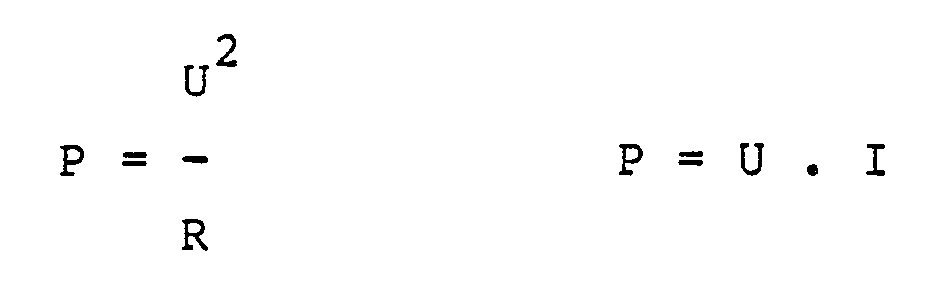
Die Heizspannung U muß sich insofern in Abhängigkeit vom Widerstand R des Sensorelementes (14) ändern und damit in Abhängigkeit der das Sensorelement (14) umgebenden Gase, damit die Heizleistung P konstant wird. Würde man die Heizleistung P nicht regeln, dann würde sich die Heizleistung P in Abhängigkeit vom Widerstand R verändern.The heating voltage U must therefore change as a function of the resistance R of the sensor element (14) and thus as a function of the gases surrounding the sensor element (14) so that the heating power P becomes constant. If the heating power P were not regulated, the heating power P would change depending on the resistance R.
Der Leistungsregler (12) stellt sicher, daß das Produkt aus Strom I und Spannung U, also die elektrische Leistung P, konstant bleibt. Die elektrische Leistung P wird im Sensorelement (14) umgesetzt. Die notwendige an dem Sensorelement (14) anliegende Spannung U wird ständig vom Leistungsregler (12) angepaßt, wobei regelmäßig die Spannung U dann kleiner wird, wenn aufgrund der Anwesenheit eines Gases der Sensorwiderstand R kleiner wird und der Leistungsregler (12) entsprechend reagiert. Daraus folgt, daß die Sensorspannung am Sensorelement eine Funktion der Gaskonzentration ist und in der Auswerteeinheit (16) ausgewertet werden kann.The power regulator (12) ensures that the product of current I and voltage U, that is to say the electrical power P, remains constant. The electrical power P is converted in the sensor element (14). The necessary voltage U applied to the sensor element (14) is constantly adapted by the power controller (12), the voltage U regularly decreasing when the sensor resistance R becomes smaller due to the presence of a gas and the power controller (12) reacts accordingly. It follows that the sensor voltage at the sensor element is a function of the gas concentration and can be evaluated in the evaluation unit (16).
Der Leistungsregler kann als eigene Baugruppe ausgebildet sein. Es ist besonders vorteilhaft, wenn die Leistungsreglung durch einen Mikroprozessor gleichzeitig mit der Signalauswertung durchgeführt wird, wobei der Mikroprozessor, der in die Auswerteeinheit (16) integriert werden kann, zusätzlich lediglich den Strom zu messen hat. In dem Leistungsregler (12) ist ein weiterer Mikroprozessor vorgesehen, der die entsprechenden Störgrößen verarbeitet und dafür sorgt, daß das Produkt aus Spannung U und Strom I, also die Leistung P, konstantgehalten wird.The power controller can be designed as a separate assembly. It is particularly advantageous if the power control is carried out by a microprocessor simultaneously with the signal evaluation, the microprocessor, which can be integrated in the evaluation unit (16), only has to measure the current. A further microprocessor is provided in the power controller (12), which processes the corresponding disturbance variables and ensures that the product of voltage U and current I, that is to say the power P, is kept constant.
Darüber hinaus kann auch, wie in Fig. 14 dargestellt, der Leistungsregler (12) als gesteuerte Konstantstromquelle ausgeführt werden. In dieser Ausführungsform befindet sich in der Auswerteeinheit (16) ein Mikroprozessor, der über die Verbindung (30) die Konstantstromquelle steuert.In addition, as shown in FIG. 14, the power regulator (12) can also be designed as a controlled constant current source. In this embodiment there is a microprocessor in the evaluation unit (16) which controls the constant current source via the connection (30).
Claims (24)
Applications Claiming Priority (12)
| Application Number | Priority Date | Filing Date | Title |
|---|---|---|---|
| DE3827426 | 1988-08-12 | ||
| DE19883827426 DE3827426A1 (en) | 1988-08-12 | 1988-08-12 | Device for carrying out a method for the purpose of identifying and quantifying unknown gaseous substances |
| DE3905993 | 1989-02-25 | ||
| DE19893905993 DE3905993A1 (en) | 1989-02-25 | 1989-02-25 | Appliance and method for the purpose of detecting oxidisable and/or reducible gases |
| DE19893907556 DE3907556A1 (en) | 1989-03-09 | 1989-03-09 | Apparatus and method for raising the selectivity of semiconductor sensors by means of controlled heating temperatures |
| DE3907556 | 1989-03-09 | ||
| DE19893917519 DE3917519A1 (en) | 1989-05-30 | 1989-05-30 | Identification appts. for unknown gaseous substances |
| DE3917519 | 1989-05-30 | ||
| DE19893917853 DE3917853A1 (en) | 1989-06-01 | 1989-06-01 | Identification appts. for unknown gaseous substances |
| DE3917853 | 1989-06-01 | ||
| DE3918684 | 1989-06-08 | ||
| DE19893918684 DE3918684A1 (en) | 1989-06-08 | 1989-06-08 | Identification appts. for unknown gaseous substances |
Publications (2)
| Publication Number | Publication Date |
|---|---|
| EP0354486A2 true EP0354486A2 (en) | 1990-02-14 |
| EP0354486A3 EP0354486A3 (en) | 1990-08-01 |
Family
ID=27544514
Family Applications (1)
| Application Number | Title | Priority Date | Filing Date |
|---|---|---|---|
| EP89114409A Withdrawn EP0354486A3 (en) | 1988-08-12 | 1989-08-04 | Apparatus for carrying out a method to identify and to quantify unknown gaseous substances |
Country Status (1)
| Country | Link |
|---|---|
| EP (1) | EP0354486A3 (en) |
Cited By (5)
| Publication number | Priority date | Publication date | Assignee | Title |
|---|---|---|---|---|
| DE4111113C2 (en) * | 1991-04-03 | 2000-09-21 | Itvi Inttech Venture Investa | Phthalocyanine sensor for the purpose of detecting nitrogen oxides in the air |
| DE4037479C2 (en) * | 1990-11-24 | 2002-04-11 | Paragon Ag | Phthalocyanine sensor for the detection of nitrogen oxides in the air |
| EP1602924A2 (en) * | 2004-06-03 | 2005-12-07 | UST Umweltsensortechnik GmbH | Apparatus and Method for detecting volatile organic compounds |
| CN1311236C (en) * | 2000-10-16 | 2007-04-18 | 纳幕尔杜邦公司 | Method and apparatus for analyzing mixtures of gases |
| US7737700B2 (en) | 2005-11-23 | 2010-06-15 | Ust Umweltsensortechnik Gmbh | Arrangement and method for detecting air ingredients |
Citations (4)
| Publication number | Priority date | Publication date | Assignee | Title |
|---|---|---|---|---|
| GB2044491A (en) * | 1979-03-07 | 1980-10-15 | Draegerwerk Ag | Automatic control of temperature |
| EP0092068A1 (en) * | 1982-04-15 | 1983-10-26 | Cerberus Ag | Gas and/or vapour alarm device |
| US4498330A (en) * | 1981-05-15 | 1985-02-12 | U.S. Industrial Products Co. | Gas detecting and monitoring device |
| WO1985001351A1 (en) * | 1983-09-15 | 1985-03-28 | Paul Kevin Clifford | Selective gas detection and measurement system |
-
1989
- 1989-08-04 EP EP89114409A patent/EP0354486A3/en not_active Withdrawn
Patent Citations (4)
| Publication number | Priority date | Publication date | Assignee | Title |
|---|---|---|---|---|
| GB2044491A (en) * | 1979-03-07 | 1980-10-15 | Draegerwerk Ag | Automatic control of temperature |
| US4498330A (en) * | 1981-05-15 | 1985-02-12 | U.S. Industrial Products Co. | Gas detecting and monitoring device |
| EP0092068A1 (en) * | 1982-04-15 | 1983-10-26 | Cerberus Ag | Gas and/or vapour alarm device |
| WO1985001351A1 (en) * | 1983-09-15 | 1985-03-28 | Paul Kevin Clifford | Selective gas detection and measurement system |
Non-Patent Citations (1)
| Title |
|---|
| TM/TECHNISCHES MESSEN, Band 54, Nr. 11, 1987, Seiten 437-438, Munchen, DE; R. BERNT: "Mikroprozessorgesteuerte Sensoren fuer brennbare Gase und Schwefelwasserstoff" * |
Cited By (6)
| Publication number | Priority date | Publication date | Assignee | Title |
|---|---|---|---|---|
| DE4037479C2 (en) * | 1990-11-24 | 2002-04-11 | Paragon Ag | Phthalocyanine sensor for the detection of nitrogen oxides in the air |
| DE4111113C2 (en) * | 1991-04-03 | 2000-09-21 | Itvi Inttech Venture Investa | Phthalocyanine sensor for the purpose of detecting nitrogen oxides in the air |
| CN1311236C (en) * | 2000-10-16 | 2007-04-18 | 纳幕尔杜邦公司 | Method and apparatus for analyzing mixtures of gases |
| EP1602924A2 (en) * | 2004-06-03 | 2005-12-07 | UST Umweltsensortechnik GmbH | Apparatus and Method for detecting volatile organic compounds |
| EP1602924A3 (en) * | 2004-06-03 | 2007-09-19 | UST Umweltsensortechnik GmbH | Apparatus and Method for detecting volatile organic compounds |
| US7737700B2 (en) | 2005-11-23 | 2010-06-15 | Ust Umweltsensortechnik Gmbh | Arrangement and method for detecting air ingredients |
Also Published As
| Publication number | Publication date |
|---|---|
| EP0354486A3 (en) | 1990-08-01 |
Similar Documents
| Publication | Publication Date | Title |
|---|---|---|
| DE3711511C1 (en) | Method for determining gas concentrations in a gas mixture and sensor for measuring thermal conductivity | |
| US5345213A (en) | Temperature-controlled, micromachined arrays for chemical sensor fabrication and operation | |
| WO1994010559A9 (en) | Temperature-controlled, micromachined arrays for chemical sensor fabrication and operation | |
| DD283866A5 (en) | METHOD FOR DETERMINING AND DEVICE FOR MEASURING THE HEAT ACCURACY OF MATERIALS | |
| DE3921526A1 (en) | DIFFUSION BARRIER WITH TEMPERATURE PROBE FOR AN ELECTROCHEMICAL GAS SENSOR | |
| EP0464244B1 (en) | Sensor for detecting reducing gases | |
| EP0801302A1 (en) | Method for measuring the absolute humidity of air | |
| DE102018122860A1 (en) | Method for operating a sensor device | |
| DE4109516C2 (en) | Device for continuously monitoring the concentrations of gaseous components in gas mixtures | |
| EP0354486A2 (en) | Apparatus for carrying out a method to identify and to quantify unknown gaseous substances | |
| DE102009047354A1 (en) | Method and control device for detecting a gas concentration of a gas from a gas mixture | |
| DE4139721C1 (en) | Simple compact gas detector for selective detection - comprise support, gallium oxide semiconducting layer, contact electrode, temp. gauge, heating and cooling elements | |
| Mielle | Managing dynamic thermal exchanges in commercial semiconduting gas sensors | |
| EP0522118B1 (en) | Device for the continuous monitoring of the concentrations of gaseous components of gas mixtures | |
| DE102013206637A1 (en) | Method for analyzing a gas | |
| DE102018108723A1 (en) | Sensor device, method for operating a sensor device and electronic assembly, comprising a sensor device | |
| DE10019010B4 (en) | Use of a chemically sensitive semiconductor material for the detection of gaseous and / or vaporous analytes in gases | |
| DE4226591C1 (en) | Gas sensor with temp. regulation circuit including resistance bridge - has control circuit for maintaining temp. of sensors in resistance bridge circuit constant, with circuit output indicating heat caused by gas | |
| EP0563613A2 (en) | Device for determining the partial pressure of gases in a gas mixture | |
| EP3729009B1 (en) | Thermal flow sensor for determining the temperature and the flow speed of a flowing measurement medium | |
| DE60033036T2 (en) | GAS SENSOR | |
| DE4210396C2 (en) | Arrangement for determining a gas partial pressure of a determination gas in a gas mixture | |
| DE10009969C2 (en) | Sensor element and method for the quantitative detection of mercury | |
| DE3905993A1 (en) | Appliance and method for the purpose of detecting oxidisable and/or reducible gases | |
| DE3827426A1 (en) | Device for carrying out a method for the purpose of identifying and quantifying unknown gaseous substances |
Legal Events
| Date | Code | Title | Description |
|---|---|---|---|
| PUAI | Public reference made under article 153(3) epc to a published international application that has entered the european phase |
Free format text: ORIGINAL CODE: 0009012 |
|
| AK | Designated contracting states |
Kind code of ref document: A2 Designated state(s): AT BE CH DE ES FR GB GR IT LI LU NL SE |
|
| PUAL | Search report despatched |
Free format text: ORIGINAL CODE: 0009013 |
|
| AK | Designated contracting states |
Kind code of ref document: A3 Designated state(s): AT BE CH DE ES FR GB GR IT LI LU NL SE |
|
| 17P | Request for examination filed |
Effective date: 19900814 |
|
| 17Q | First examination report despatched |
Effective date: 19920219 |
|
| STAA | Information on the status of an ep patent application or granted ep patent |
Free format text: STATUS: THE APPLICATION IS DEEMED TO BE WITHDRAWN |
|
| 18D | Application deemed to be withdrawn |
Effective date: 19920630 |