EP0354210B1 - Tail fin unit for a projectile - Google Patents
Tail fin unit for a projectile Download PDFInfo
- Publication number
- EP0354210B1 EP0354210B1 EP88902175A EP88902175A EP0354210B1 EP 0354210 B1 EP0354210 B1 EP 0354210B1 EP 88902175 A EP88902175 A EP 88902175A EP 88902175 A EP88902175 A EP 88902175A EP 0354210 B1 EP0354210 B1 EP 0354210B1
- Authority
- EP
- European Patent Office
- Prior art keywords
- fin unit
- long rod
- projectile according
- projectile
- fins
- Prior art date
- Legal status (The legal status is an assumption and is not a legal conclusion. Google has not performed a legal analysis and makes no representation as to the accuracy of the status listed.)
- Expired - Lifetime
Links
- 239000000463 material Substances 0.000 claims abstract description 14
- 238000000465 moulding Methods 0.000 claims abstract description 13
- 239000004033 plastic Substances 0.000 claims abstract description 12
- 229920003023 plastic Polymers 0.000 claims abstract description 12
- 229920003235 aromatic polyamide Polymers 0.000 claims abstract description 5
- 239000003822 epoxy resin Substances 0.000 claims abstract description 5
- 229920000647 polyepoxide Polymers 0.000 claims abstract description 5
- 238000000034 method Methods 0.000 claims description 10
- 229920001169 thermoplastic Polymers 0.000 claims description 9
- 229920001187 thermosetting polymer Polymers 0.000 claims description 9
- 239000004416 thermosoftening plastic Substances 0.000 claims description 9
- 238000004519 manufacturing process Methods 0.000 claims description 6
- 239000000203 mixture Substances 0.000 claims description 6
- 229920000728 polyester Polymers 0.000 claims description 5
- 239000004760 aramid Substances 0.000 claims description 4
- 229920001643 poly(ether ketone) Polymers 0.000 claims description 4
- 239000012779 reinforcing material Substances 0.000 claims description 4
- 238000001746 injection moulding Methods 0.000 claims description 3
- 229920000106 Liquid crystal polymer Polymers 0.000 claims description 2
- 239000004977 Liquid-crystal polymers (LCPs) Substances 0.000 claims description 2
- 239000004952 Polyamide Substances 0.000 claims description 2
- 238000007373 indentation Methods 0.000 claims description 2
- 229920002492 poly(sulfone) Polymers 0.000 claims description 2
- 229920002647 polyamide Polymers 0.000 claims description 2
- 239000004417 polycarbonate Substances 0.000 claims description 2
- 229920000515 polycarbonate Polymers 0.000 claims description 2
- 229920001601 polyetherimide Polymers 0.000 claims description 2
- -1 polyethersulphones Polymers 0.000 claims description 2
- 238000002679 ablation Methods 0.000 abstract description 10
- 229920000271 Kevlar® Polymers 0.000 abstract description 4
- 238000010438 heat treatment Methods 0.000 abstract description 4
- 239000004761 kevlar Substances 0.000 abstract description 4
- 230000003628 erosive effect Effects 0.000 abstract description 3
- 239000003380 propellant Substances 0.000 abstract description 3
- 229920001225 polyester resin Polymers 0.000 abstract 1
- 239000004645 polyester resin Substances 0.000 abstract 1
- 230000008901 benefit Effects 0.000 description 4
- 229910052751 metal Inorganic materials 0.000 description 4
- 239000002184 metal Substances 0.000 description 4
- 239000002131 composite material Substances 0.000 description 3
- 239000000206 moulding compound Substances 0.000 description 3
- 230000002745 absorbent Effects 0.000 description 2
- 239000002250 absorbent Substances 0.000 description 2
- 239000011248 coating agent Substances 0.000 description 2
- 238000000576 coating method Methods 0.000 description 2
- 238000013016 damping Methods 0.000 description 2
- 230000000694 effects Effects 0.000 description 2
- 238000001125 extrusion Methods 0.000 description 2
- 230000005484 gravity Effects 0.000 description 2
- 230000004048 modification Effects 0.000 description 2
- 238000012986 modification Methods 0.000 description 2
- 230000035515 penetration Effects 0.000 description 2
- 229910000838 Al alloy Inorganic materials 0.000 description 1
- 239000004429 Calibre Substances 0.000 description 1
- OKTJSMMVPCPJKN-UHFFFAOYSA-N Carbon Chemical compound [C] OKTJSMMVPCPJKN-UHFFFAOYSA-N 0.000 description 1
- 229910001080 W alloy Inorganic materials 0.000 description 1
- 230000001154 acute effect Effects 0.000 description 1
- 229910052799 carbon Inorganic materials 0.000 description 1
- 239000000969 carrier Substances 0.000 description 1
- 238000001816 cooling Methods 0.000 description 1
- 239000007789 gas Substances 0.000 description 1
- 239000011521 glass Substances 0.000 description 1
- LNEPOXFFQSENCJ-UHFFFAOYSA-N haloperidol Chemical compound C1CC(O)(C=2C=CC(Cl)=CC=2)CCN1CCCC(=O)C1=CC=C(F)C=C1 LNEPOXFFQSENCJ-UHFFFAOYSA-N 0.000 description 1
- 238000013007 heat curing Methods 0.000 description 1
- 238000011065 in-situ storage Methods 0.000 description 1
- 238000003754 machining Methods 0.000 description 1
- 238000012423 maintenance Methods 0.000 description 1
- 238000002844 melting Methods 0.000 description 1
- 230000008018 melting Effects 0.000 description 1
- 230000000149 penetrating effect Effects 0.000 description 1
- 229920000642 polymer Polymers 0.000 description 1
- 239000002861 polymer material Substances 0.000 description 1
- 239000002990 reinforced plastic Substances 0.000 description 1
- 230000002787 reinforcement Effects 0.000 description 1
- 230000003014 reinforcing effect Effects 0.000 description 1
- 230000003068 static effect Effects 0.000 description 1
- 238000003860 storage Methods 0.000 description 1
- 239000012815 thermoplastic material Substances 0.000 description 1
- 239000004634 thermosetting polymer Substances 0.000 description 1
- 238000001721 transfer moulding Methods 0.000 description 1
Images

Classifications
-
- F—MECHANICAL ENGINEERING; LIGHTING; HEATING; WEAPONS; BLASTING
- F42—AMMUNITION; BLASTING
- F42B—EXPLOSIVE CHARGES, e.g. FOR BLASTING, FIREWORKS, AMMUNITION
- F42B10/00—Means for influencing, e.g. improving, the aerodynamic properties of projectiles or missiles; Arrangements on projectiles or missiles for stabilising, steering, range-reducing, range-increasing or fall-retarding
- F42B10/02—Stabilising arrangements
- F42B10/04—Stabilising arrangements using fixed fins
- F42B10/06—Tail fins
Definitions
- This invention relates to a non-metallic tail fin for a subcalibre kinetic energy projectile, herein called a long rod projectile, as described in the pre-characterising part of claim 1 and conventionally fired with an associated surrounding discard sabot from a larger calibre gun so as to impart a supersonic velocity and thereby high kinetic energy to the projectile.
- a subcalibre kinetic energy projectile herein called a long rod projectile
- Such projectiles are known from EP-A-0 174 082.
- a projectile of this type is usually fin stabilised, and comprises a dense, cylindrical penetrator having a tail fin unit attached to its rear end.
- the tail fin unit consists of a fin unit body member coaxially attached to the projectile, with a plurality of radially protrusive fins extending therefrom.
- the body member is typified by an average density of at least 7gm cm ⁇ 3, more usually at least 15gm cm ⁇ 3, and a length-to-diameter ratio of at least 10:1.
- the fin unit on a long rod projectile
- the fin unit also provides the projectile with an aerodynamically-induced rate of spin during its flight which is sufficient to even out any asymmetrical in-flight forces caused by manufacturing asymmetrics in the shape or balance of the projectile which would otherwise give rise to unacceptable inaccuracies at the target.
- This spin rate is typically 20-200 revolutions per second and usually represents only a small fraction of the rate of spin imparted to non-finned, spin-stabilised projectiles fired from guns (spin-rates, in the later type of projectile, of several hundred revolutions per second are typical). However, this spin rate must be greater than the spin rate at which the long rod projectile exhibits spin yaw resonance, which is a spin rate at which the yaw of the projectile builds up during its flight to the target.
- tail fin units having lightweight metal fins of, for example, aluminium alloy.
- the light weight of these fins ensure that once fitted, the mass of the unit causes no significant rearward shift in the centre of gravity of the projectile.
- the static margin between the projectile's centre of gravity and centre of pressure is not, therefore, significantly reduced, which means that the stability of the projectile in flight is not unduly affected.
- An additional reason for using lightweight metal fins is that it ensures a high proportion of the overall mass of the projectile is concentrated in the penetrator.
- the cost of producing lightweight metal tail fin units may be kept to a minimum by extruding each unit in one piece.
- the process of extrusion produces fins which are parallel to the extruding axis (which axis also defines the axis of the unit) and are of constant cross-sectional shape and area in keeping with the shape of the extrusion die. Further modification to the contour of the fins is therefore essential to ensure the units are capable of imparting spin to an in-flight projectile.
- This modification normally involves machining, at an acute angle to the axis of the unit, a leading or trailing edge chamfer on each fin which creates an asymmetric lateral force on each fin so as to transmit an axial torque to the projectile and thereby provide the necessary slow rate of spin.
- these chamfers are susceptible to damage during the launch of the projectile and its subsequent flight to the target, and this damage can cause variation in spin rate resulting in a catastrophic effect on flight performance.
- Fin units of this type are subject to extremely high in-bore propellant flash temperatures and subsequent aerodynamic heating temperatures which can well exceed the melting point of a lightweight metal. Consequently such fin units must be protected from damage by the provision of a heat resistant or a heat absorbent coating to prevent distortion of the fin profile.
- One particular heat absorbent coating known for this purpose is described in GB1604865 and comprises a thin heat-cured, homogeneous layer of an epoxy resin which will ablate uniformly and consistently at the temperatures encountered, thereby ensuring continuously balanced maintenance of the fin profiles and constancy of spin rate.
- the present invention seeks to provide a light-weight, mouldable, reinforced plastics material fin unit having a profile which is less sensitive to uneven in-flight ablation so as to ensure a predetermined velocity-related spin rate throughout flight.
- the invention further seeks to employ controlled in-flight ablation to achieve a drag reduction during flight.
- a tail fin unit for a long rod projectile comprises an axisymmetric fin unit body member coaxially attachable to the projectile and having a plurality of radially protrusive fins, characterised in that the fin unit body and the fins comprise an integral plastics material moulding and the fins are each disposed as a helix of constant pitch around the longitudinal axis of the moulding.
- the principal advantages of the present tail fin unit is that by the use of plastic helical fins of constant pitch to impart the necessary in-flight rate of spin to the projectile, any unequal in-flight ablation of the leading edges of these fins caused by aerodynamic heating will occur without detriment to the spin rate of the long rod projectile.
- the process of ablation can itself be turned to advantage because by an appropriate selection of plastics material, it can be used to bring about a significant reduction in the size (and hence surface area) of the fins as they burn away from their leading edges.
- the surface area hence size of the fins are normally selected to ensure they are large enough to perform their primary function of damping out yaw imparted to the projectile at launch.
- the plastics material is preferably a polymer material comprising a thermoplastic or a thermoset resin composition.
- Suitable thermoset compositions include thermoset polyesters and cured epoxy resins
- suitable thermoplastics include thermoplastic polyesters, polyamides, thermoplastic liquid crystal polymers, polycarbonates, polysulphones, polyethersulphones, polyetherimides, and polyetherketones (PEEK).
- the material may be filled with reinforcing materials comprised by randomly disposed, chopped strands of glass, aramid or carbon fibres.
- the fibres preferably constitute from 2 to 45% by volume of the plastics material and preferably have an average length of up to 25mm, more preferably of from 0.25mm to 25mm.
- the rear end of the penetrator is preferably encased within an axial recess within the fin unit body member to provide the necessary attachment, and preferably includes one or more radial protrusions or indentations to prevent relative axial and rotational movement of the penetrator with respect to the tail fin unit.
- the body member preferably has an average density of at least 7gm cm ⁇ 3, more preferably at least 15gm cm ⁇ 3, and preferably has a length-to-diameter ratio of at least 10:1.
- the present tail fin unit is, in accordance with claim 14 of this specification, conveniently manufactured by the steps of (a) centrally locating one end of a cylindrical fin unit holding member in a removable tail fin unit mould to close said mould, (b) moulding the tail fin unit onto the said one end in the mould, and (c) withdrawing the moulded tail fin unit from the mould.
- Step (b) preferably comprises the process of injection moulding.
- step (c) may be accomplished by axially twisting and separating the mould and holding member relative to one another in such a manner that the moulded fin unit follows a helical path through the mould which is in the same direction and of the same pitch as the fins. In this way, the moulded fin unit may be extracted from the mould without first dismantling those portions of the mould adjacent the fins, which thereby provides a simple and easily automated fin unit withdrawal step.
- the fin unit moulding is preferably directly attached to the rear end of the long rod projectile during the moulding process.
- the said one end of the holding member is screw threaded to allow subsequent rotational detachment of the holding member from the moulded tail fin unit.
- the fin unit 10 depicted in Figures 1, 2 and 3 comprises a central cylinder 12 having an axial recess 14 in its forward end and having six radially protrusive fins 16 each extending along the length of the cylinder 12 as a right-handed helix of 20 metre pitch.
- Each fin 16 widens at the root 18 where it adjoins the cylinder 12 and tapers down towards the cylinder 12 at its leading edge 20.
- the taper on each leading edge 20 is symmetrically rounded to ensure that the impact of each leading edge 20 with axial air flow past the fin unit 10 imparts no axial torque thereto.
- the fin tips 22 are rounded and have a total angle A of twist from end to end of the unit which, on a unit length of 100mm, is 1.8 o .
- the fin unit 10 is shown attached to the rear end 24 of a cylindrical penetrator 26 made of tungsten alloy.
- the penetrator 26 has a nose portion 28 at its forward end and has a length-to-diameter ratio of 12:1.
- the attachment between the fin unit 10 and rear end 24 is provided by knurling 30 on the encased cylindrical surface of the rear end 24, which engages with the interior of the recess 14.
- the unit 10 is manufactured by injecting a molten thermosetting composition or thermoplastic material incorporating chopped reinforcing fibres of Kevlar (Registered Trade Mark) aramid into a removable fin unit mould (not shown) within which the knurled rear end 24 of the projectile body 26 has been centrally located to close the mould.
- a process of transfer moulding may alternatively be employed.
- thermosetting compositions employed were the moulding compounds E20328, which is an epoxy resin moulding compound incorporating chopped Kevlar fibres which is manufactured by the Fiberlite Corporation of Winona, Minnesota, USA and Freemix 43-2067, which is a thermosetting polyester moulding compound incorporating about 5% by weight of 6mm chopped Kevlar fibres and supplied by Freeman Polymers Division of PO Box 8, Ellesmere Port, South Wirral, England. Thereafter the fin unit moulding is set in situ either by cooling (in the case of a thermoplastic) or heat curing (in the case of a thermosetting composition), and the fin unit mould removed.
- E20328 is an epoxy resin moulding compound incorporating chopped Kevlar fibres which is manufactured by the Fiberlite Corporation of Winona, Minnesota, USA and Freemix 43-2067
- thermosetting polyester moulding compound incorporating about 5% by weight of 6mm chopped Kevlar fibres and supplied by Freeman Polymers Division of PO Box 8, Ellesmere Port, South Wirral, England.
- the removal operation is preferably accomplished by axially twisting and separating the mould and projectile body 26 relative to one another in such a manner that the moulded tail fin unit 10 follows a helical path through the mould in the same direction and of the same pitch as the fins 16.
- the moulded unit 10 may be extracted from the mould without dismantling those portions of the mould surrounding the fins 16, so that high production rates of fin units are made possible using only one or a small number of moulds.
- Composite mouldings of this type have been found capable of resisting gun chamber pressures of up to 4000kg cm ⁇ 2.
- the fin unit 110 depicted in Figure 4 is identical to that illustrated in Figures 1, 2 and 3 except that the recess 114 has an axially threaded portion 134 which engages with a cooperating threaded portion 136 on the rear end 124 of a second cylindrical projectile body 126.
- the thread on the fin unit 110 may be right-handed or left-handed according to the type of gun from which the projectile is to be fired.
- Manufacture of the fin unit 110 is, again, identical to the manufacture of the fin unit 10 except that in the case of the fin unit 110, a cylindrical fin unit holder (not shown) with a threaded portion on its rear end may be used in place of the projectile body member 126 itself.
- the threaded portion on the holder is identical in shape and size to the threaded portion 136 on the projectile body 126. This allows for separate storage of the moulded fin unit 110 once it has been rotationally detached from the holder, so that the fin unit 110 may then be attached at a later time to the threaded portion 136 on projectile body 126.
- each of the fin units 10, 110 is subject to erosion by burning propellant gases during launch, and thereafter to in-flight ablation at the leading edges 20, 120 of the fins 16, 116 due to aerodynamic heating.
- Ablation may not occur evenly but because the fins 16, 116 are of constant pitch, any loss of material from their leading edges 20, 120 will occur without detriment to the spin rate of the projectile. Since erosion through ablation will reduce the size hence surface area of the fins, any significant ablation will also have the effect of reducing the net drag of the projectile during its flight once the fins have performed their primary function of damping out yaw imparted at launch.
Landscapes
- Physics & Mathematics (AREA)
- Fluid Mechanics (AREA)
- Engineering & Computer Science (AREA)
- General Engineering & Computer Science (AREA)
- Injection Moulding Of Plastics Or The Like (AREA)
- Extrusion Moulding Of Plastics Or The Like (AREA)
- Toys (AREA)
Abstract
Description
- This invention relates to a non-metallic tail fin for a subcalibre kinetic energy projectile, herein called a long rod projectile, as described in the pre-characterising part of claim 1 and conventionally fired with an associated surrounding discard sabot from a larger calibre gun so as to impart a supersonic velocity and thereby high kinetic energy to the projectile. Such projectiles are known from EP-A-0 174 082.
- Long rod projectiles are known for their excellent penetrating power and are normally employed in direct fire mode, that is to say they are fired along a substantially flat trajectory, for attacking armoured targets which may range from relatively lightly-armoured personnel carriers, helicopters and aircraft to heavily-armoured battle tanks. A projectile of this type is usually fin stabilised, and comprises a dense, cylindrical penetrator having a tail fin unit attached to its rear end. The tail fin unit consists of a fin unit body member coaxially attached to the projectile, with a plurality of radially protrusive fins extending therefrom. In order to provide the required high penetration power, the body member is typified by an average density of at least 7gm cm⁻³, more usually at least 15gm cm⁻³, and a length-to-diameter ratio of at least 10:1.
- The main purposes of a tail fin unit on a long rod projectile are to dampen out yaw imparted to the projectile at launch and thereafter stabilise the flight of the projectile to the target. However, in the fin-stabilised long rod projectile of the type herein defined, the fin unit also provides the projectile with an aerodynamically-induced rate of spin during its flight which is sufficient to even out any asymmetrical in-flight forces caused by manufacturing asymmetrics in the shape or balance of the projectile which would otherwise give rise to unacceptable inaccuracies at the target. This spin rate is typically 20-200 revolutions per second and usually represents only a small fraction of the rate of spin imparted to non-finned, spin-stabilised projectiles fired from guns (spin-rates, in the later type of projectile, of several hundred revolutions per second are typical). However, this spin rate must be greater than the spin rate at which the long rod projectile exhibits spin yaw resonance, which is a spin rate at which the yaw of the projectile builds up during its flight to the target.
- In order to optimise the penetration and in-flight stability of a long rod projectile it is known to use tail fin units having lightweight metal fins of, for example, aluminium alloy. The light weight of these fins ensure that once fitted, the mass of the unit causes no significant rearward shift in the centre of gravity of the projectile. The static margin between the projectile's centre of gravity and centre of pressure is not, therefore, significantly reduced, which means that the stability of the projectile in flight is not unduly affected. An additional reason for using lightweight metal fins is that it ensures a high proportion of the overall mass of the projectile is concentrated in the penetrator.
- The cost of producing lightweight metal tail fin units may be kept to a minimum by extruding each unit in one piece. The process of extrusion produces fins which are parallel to the extruding axis (which axis also defines the axis of the unit) and are of constant cross-sectional shape and area in keeping with the shape of the extrusion die. Further modification to the contour of the fins is therefore essential to ensure the units are capable of imparting spin to an in-flight projectile. This modification normally involves machining, at an acute angle to the axis of the unit, a leading or trailing edge chamfer on each fin which creates an asymmetric lateral force on each fin so as to transmit an axial torque to the projectile and thereby provide the necessary slow rate of spin. However, these chamfers are susceptible to damage during the launch of the projectile and its subsequent flight to the target, and this damage can cause variation in spin rate resulting in a catastrophic effect on flight performance.
- Fin units of this type are subject to extremely high in-bore propellant flash temperatures and subsequent aerodynamic heating temperatures which can well exceed the melting point of a lightweight metal. Consequently such fin units must be protected from damage by the provision of a heat resistant or a heat absorbent coating to prevent distortion of the fin profile. One particular heat absorbent coating known for this purpose is described in GB1604865 and comprises a thin heat-cured, homogeneous layer of an epoxy resin which will ablate uniformly and consistently at the temperatures encountered, thereby ensuring continuously balanced maintenance of the fin profiles and constancy of spin rate.
- Clearly it would be desirable to extend this ablative principle to a lighter-weight and more simply fabricated fin unit made entirely from a plastics material, but in order to withstand gun chamber pressures the plastics material would require reinforcement, resulting in a heterogeneous composite which would not ablate with sufficient uniformity to maintain a constant spin rate.
- The present invention seeks to provide a light-weight, mouldable, reinforced plastics material fin unit having a profile which is less sensitive to uneven in-flight ablation so as to ensure a predetermined velocity-related spin rate throughout flight. The invention further seeks to employ controlled in-flight ablation to achieve a drag reduction during flight.
- In accordance with claim 1 of the present specification a tail fin unit for a long rod projectile comprises an axisymmetric fin unit body member coaxially attachable to the projectile and having a plurality of radially protrusive fins, characterised in that the fin unit body and the fins comprise an integral plastics material moulding and the fins are each disposed as a helix of constant pitch around the longitudinal axis of the moulding.
- The principal advantages of the present tail fin unit is that by the use of plastic helical fins of constant pitch to impart the necessary in-flight rate of spin to the projectile, any unequal in-flight ablation of the leading edges of these fins caused by aerodynamic heating will occur without detriment to the spin rate of the long rod projectile. Furthermore, the process of ablation can itself be turned to advantage because by an appropriate selection of plastics material, it can be used to bring about a significant reduction in the size (and hence surface area) of the fins as they burn away from their leading edges. The surface area hence size of the fins are normally selected to ensure they are large enough to perform their primary function of damping out yaw imparted to the projectile at launch. Thereafter, only a fraction of this surface area is required for the purpose of maintaining in-flight spin and stability, so that much of the surface area required at launch contributes to unwanted drag on the projectile once in flight. Controlled in-flight ablation from the leading edge can therefore have the benefit of reducing drag as the flight of the projectile proceeds.
- The plastics material is preferably a polymer material comprising a thermoplastic or a thermoset resin composition. Suitable thermoset compositions include thermoset polyesters and cured epoxy resins, whereas suitable thermoplastics include thermoplastic polyesters, polyamides, thermoplastic liquid crystal polymers, polycarbonates, polysulphones, polyethersulphones, polyetherimides, and polyetherketones (PEEK). The material may be filled with reinforcing materials comprised by randomly disposed, chopped strands of glass, aramid or carbon fibres. The fibres preferably constitute from 2 to 45% by volume of the plastics material and preferably have an average length of up to 25mm, more preferably of from 0.25mm to 25mm.
- Any suitable method of moulding known to those skilled in the art may be employed in the manufacture of the present tail fin unit, but injection moulding is preferred. The rear end of the penetrator is preferably encased within an axial recess within the fin unit body member to provide the necessary attachment, and preferably includes one or more radial protrusions or indentations to prevent relative axial and rotational movement of the penetrator with respect to the tail fin unit.
- The body member preferably has an average density of at least 7gm cm⁻³, more preferably at least 15gm cm⁻³, and preferably has a length-to-diameter ratio of at least 10:1.
- The present tail fin unit is, in accordance with
claim 14 of this specification, conveniently manufactured by the steps of (a) centrally locating one end of a cylindrical fin unit holding member in a removable tail fin unit mould to close said mould, (b) moulding the tail fin unit onto the said one end in the mould, and (c) withdrawing the moulded tail fin unit from the mould. Step (b) preferably comprises the process of injection moulding. It is one further advantage of the present tail fin unit that step (c) may be accomplished by axially twisting and separating the mould and holding member relative to one another in such a manner that the moulded fin unit follows a helical path through the mould which is in the same direction and of the same pitch as the fins. In this way, the moulded fin unit may be extracted from the mould without first dismantling those portions of the mould adjacent the fins, which thereby provides a simple and easily automated fin unit withdrawal step. - The fin unit moulding is preferably directly attached to the rear end of the long rod projectile during the moulding process. Alternativly, the said one end of the holding member is screw threaded to allow subsequent rotational detachment of the holding member from the moulded tail fin unit.
- Embodiments of the tail fin units according to this invention and of long rod projectiles incorporating same will now be described by way of example only with reference to the accompanying drawings of which
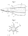
- Figure 1 is a partial side elevation of a first embodiment, showing a long rod projectile having a helical fin unit attached to its rear end,
- Figure 2 is a cross-section view of the projectile of Figure 1 taken along line I-I,
- Figure 3 is a longitudinal section of the projectile of Figure 2 taken along line II-II, and
- Figure 4 is a longitudinal section, similar to that shown in Figure 3, of a second embodiment which is taken through the rear portion of a long rod projectile having a helical fin unit screwed onto its rear end.
- The
fin unit 10 depicted in Figures 1, 2 and 3 comprises acentral cylinder 12 having anaxial recess 14 in its forward end and having six radiallyprotrusive fins 16 each extending along the length of thecylinder 12 as a right-handed helix of 20 metre pitch. Each fin 16 widens at theroot 18 where it adjoins thecylinder 12 and tapers down towards thecylinder 12 at its leadingedge 20. The taper on each leadingedge 20 is symmetrically rounded to ensure that the impact of each leadingedge 20 with axial air flow past thefin unit 10 imparts no axial torque thereto. Thefin tips 22 are rounded and have a total angle A of twist from end to end of the unit which, on a unit length of 100mm, is 1.8o. Thefin unit 10 is shown attached to therear end 24 of acylindrical penetrator 26 made of tungsten alloy. Thepenetrator 26 has anose portion 28 at its forward end and has a length-to-diameter ratio of 12:1. The attachment between thefin unit 10 andrear end 24 is provided by knurling 30 on the encased cylindrical surface of therear end 24, which engages with the interior of therecess 14. - The
unit 10 is manufactured by injecting a molten thermosetting composition or thermoplastic material incorporating chopped reinforcing fibres of Kevlar (Registered Trade Mark) aramid into a removable fin unit mould (not shown) within which the knurledrear end 24 of theprojectile body 26 has been centrally located to close the mould. A process of transfer moulding may alternatively be employed. Examples of aramid-containing thermosetting compositions employed were the moulding compounds E20328, which is an epoxy resin moulding compound incorporating chopped Kevlar fibres which is manufactured by the Fiberlite Corporation of Winona, Minnesota, USA and Freemix 43-2067, which is a thermosetting polyester moulding compound incorporating about 5% by weight of 6mm chopped Kevlar fibres and supplied by Freeman Polymers Division of PO Box 8, Ellesmere Port, South Wirral, England. Thereafter the fin unit moulding is set in situ either by cooling (in the case of a thermoplastic) or heat curing (in the case of a thermosetting composition), and the fin unit mould removed. The removal operation is preferably accomplished by axially twisting and separating the mould andprojectile body 26 relative to one another in such a manner that the mouldedtail fin unit 10 follows a helical path through the mould in the same direction and of the same pitch as thefins 16. In this way, themoulded unit 10 may be extracted from the mould without dismantling those portions of the mould surrounding thefins 16, so that high production rates of fin units are made possible using only one or a small number of moulds. Composite mouldings of this type have been found capable of resisting gun chamber pressures of up to 4000kg cm⁻². - In the second embodiment (see Figure 4), the basic structure is very similar to that described with reference to Figures 1 to 3 and, accordingly, the same reference numerals as used in Figures 1 to 3 but with the prefix "1" have been used in Figure 4.
- The
fin unit 110 depicted in Figure 4 is identical to that illustrated in Figures 1, 2 and 3 except that therecess 114 has an axially threadedportion 134 which engages with a cooperating threadedportion 136 on therear end 124 of a secondcylindrical projectile body 126. The thread on thefin unit 110 may be right-handed or left-handed according to the type of gun from which the projectile is to be fired. Manufacture of thefin unit 110 is, again, identical to the manufacture of thefin unit 10 except that in the case of thefin unit 110, a cylindrical fin unit holder (not shown) with a threaded portion on its rear end may be used in place of theprojectile body member 126 itself. The threaded portion on the holder is identical in shape and size to the threadedportion 136 on theprojectile body 126. This allows for separate storage of the mouldedfin unit 110 once it has been rotationally detached from the holder, so that thefin unit 110 may then be attached at a later time to the threadedportion 136 onprojectile body 126. - In use, each of the
fin units leading edges fins fins edges
Claims (17)
- A long rod projectile comprising a cylindrical penetrator (26,126) having a rear end (24,124) coaxially attached to a tail fin unit (10,110) which comprises an axisymmetric fin unit body member (12,112) having a plurality of radially protrusive fins (16,116), characterised in that the fin unit body (12,112) and the fins (16,116) comprise an integral plastics material moulding and the fins (16, 116) are each disposed as a helix of constant pitch around the longitudinal axis of the moulding.
- A long rod projectile according to claim 1 characterised in that the plastics material comprises either a thermoset composition or a thermoplastic.
- A long rod projectile according to claim 2 characterised in that the thermoset composition comprises a cured epoxy resin or a thermoset polyester.
- A long rod projectile according to claim 2 characterised in that the thermoplastic is seleted from the group consisting of thermoplastic polyesters, polyamides, thermoplastic liquid crystal polymers, polycarbonates, polysulphones, polyethersulphones, polyetherimides, and polyetherketones (PEEK).
- A long rod projectile according to claim 1 characterised in that the plastics material contains chopped fibres of a reinforcing material.
- A long rod projectile according to claim 5 characterised in that the plastics material contains from 2% to 45% by volume of the reinforcing material.
- A long rod projectile according to claim 5 characterised in that the average length of the chopped fibres is from 0.25mm to 25mm.
- A long rod projectile according to any one of claims 5 to 7 characterised in that the reinforcing material is an aramid fibre.
- A long rod projectile according to claim 1 characterised in that the moulding is manufactured by an injection moulding process.
- A long rod projectile according to any preceding claim characterised in that the rear end (24,124) of the penetrator (26,126) is encased within an axial recess (14,114) in the fin unit body member (12,112).
- A long rod projectile according to claim 10 characterised in that the encased rear end (24,124) of the penetrator (26,126) is provided with one or more radial protrusions or indentations (30,136) to prevent relative axial and rotational movement of the penetrator (26,126) with respect to the tail fin unit (10,110).
- A long rod projectile according to claim 11 characterised in that the cylindrical surface of the encased rear end (24) of the penetrator (26) is provided with knurling (30).
- A long rod projectile according to claim 10 characterised in that the axial recess (14) in the fin unit body member (110) and the rear end (124) of the penetrator (126) are each provided with co-operating screw threaded portions (134,136).
- A process for manufacturing a long rod projectile according to claim 1 including the steps of (a) centrally locating one end of a cylindrical fin unit holding member in a removable tail fin unit mould to close said mould, (b) moulding the tail fin unit onto the said one end in the mould, and (c) removing the mould from the moulded tail fin unit.
- A process according to claim 14 characterised in that step (c) is accomplished by axially twisting and separating the mould and holding member relative to one another so that the moulded tail fin unit follows a helical path through the mould in the same direction and of the same pitch as the fins.
- A process according to claim 14 characterised in that the said one end comprises the rear end of the cylindrical penetrator.
- A process according to claim 14 characterised in that the said one end of the holding member is screw threaded to allow rotational detachment of the holding member from the moulded tail fin unit.
Applications Claiming Priority (2)
| Application Number | Priority Date | Filing Date | Title |
|---|---|---|---|
| GB8706250 | 1987-03-17 | ||
| GB878706250A GB8706250D0 (en) | 1987-03-17 | 1987-03-17 | Tail fin unit for projectile |
Publications (2)
| Publication Number | Publication Date |
|---|---|
| EP0354210A1 EP0354210A1 (en) | 1990-02-14 |
| EP0354210B1 true EP0354210B1 (en) | 1993-12-08 |
Family
ID=10614054
Family Applications (1)
| Application Number | Title | Priority Date | Filing Date |
|---|---|---|---|
| EP88902175A Expired - Lifetime EP0354210B1 (en) | 1987-03-17 | 1988-03-09 | Tail fin unit for a projectile |
Country Status (8)
| Country | Link |
|---|---|
| EP (1) | EP0354210B1 (en) |
| AU (1) | AU600810B2 (en) |
| BR (1) | BR8807422A (en) |
| CA (1) | CA1323246C (en) |
| DE (1) | DE3886209T2 (en) |
| GB (2) | GB8706250D0 (en) |
| IL (1) | IL85710A0 (en) |
| WO (1) | WO1988007169A1 (en) |
Cited By (1)
| Publication number | Priority date | Publication date | Assignee | Title |
|---|---|---|---|---|
| US9644929B1 (en) | 2013-12-03 | 2017-05-09 | Michael S. Bradbury | Pilum bullet and cartridge |
Families Citing this family (7)
| Publication number | Priority date | Publication date | Assignee | Title |
|---|---|---|---|---|
| DE3927917A1 (en) * | 1989-08-24 | 1991-02-28 | Rheinmetall Gmbh | WING STABILIZED SHELL |
| DE4007197C2 (en) * | 1990-03-07 | 1997-07-03 | Deutsch Franz Forsch Inst | Tail unit for a high-speed bullet |
| KR920010249A (en) * | 1990-11-09 | 1992-06-26 | 앨리언트 테크시스템스 인코오포레이티드 | Ammunition fins with melt and warp resistance |
| US5158509A (en) * | 1990-12-14 | 1992-10-27 | The United States Of America As Represented By The United States Department Of Energy | Composite stabilizer unit |
| GB2268575A (en) * | 1992-07-09 | 1994-01-12 | Secr Defence | Tail fin unit |
| GB0004347D0 (en) * | 2000-02-25 | 2000-04-12 | Victrex Mfg Ltd | Lightweight ablative materials |
| CN111707145B (en) * | 2020-06-10 | 2022-09-09 | 宁波曙翔新材料股份有限公司 | Loading, ablation and heat-proof integrated composite material missile wing and rudder for hypersonic missile and preparation method thereof |
Family Cites Families (9)
| Publication number | Priority date | Publication date | Assignee | Title |
|---|---|---|---|---|
| BE425483A (en) * | 1937-01-04 | |||
| FR1061958A (en) * | 1952-05-19 | 1954-04-16 | Le Moulage De Prec | Tailoring improvements |
| FR1077083A (en) * | 1953-03-20 | 1954-11-04 | Soc Tech De Rech Ind | Tail for projectiles |
| FR1288365A (en) * | 1961-04-07 | 1962-03-24 | Oregon Etablissements Fuer Pat | New fletched projectile |
| FR1307270A (en) * | 1961-06-08 | 1962-10-26 | Le Ministre Des Armees Terre D | Tailplane for projectile and method of assembly |
| FR2020467A5 (en) * | 1969-01-29 | 1970-07-10 | Losfeld Andre | Projectile adaptable as hand grenade or - self-propelled mortar bomb |
| EP0174082A1 (en) * | 1984-07-23 | 1986-03-12 | Judd Engineering Limited | Projectile stabilising fin unit |
| DE3517125A1 (en) * | 1985-05-11 | 1986-11-13 | Rheinmetall GmbH, 4000 Düsseldorf | SUB-CALIBRARY FLOOR |
| FR2599829B1 (en) * | 1986-06-05 | 1990-04-13 | France Etat Armement | FIXTURE FOR ARROW-TYPE KINETIC ENERGY PROJECTILE |
-
1987
- 1987-03-17 GB GB878706250A patent/GB8706250D0/en active Pending
-
1988
- 1988-03-09 EP EP88902175A patent/EP0354210B1/en not_active Expired - Lifetime
- 1988-03-09 WO PCT/GB1988/000179 patent/WO1988007169A1/en not_active Ceased
- 1988-03-09 BR BR888807422A patent/BR8807422A/en not_active IP Right Cessation
- 1988-03-09 AU AU13914/88A patent/AU600810B2/en not_active Ceased
- 1988-03-09 DE DE3886209T patent/DE3886209T2/en not_active Expired - Fee Related
- 1988-03-09 GB GB8920302A patent/GB2228987B/en not_active Expired - Lifetime
- 1988-03-11 IL IL85710A patent/IL85710A0/en unknown
- 1988-03-16 CA CA000561567A patent/CA1323246C/en not_active Expired - Fee Related
Cited By (1)
| Publication number | Priority date | Publication date | Assignee | Title |
|---|---|---|---|---|
| US9644929B1 (en) | 2013-12-03 | 2017-05-09 | Michael S. Bradbury | Pilum bullet and cartridge |
Also Published As
| Publication number | Publication date |
|---|---|
| AU600810B2 (en) | 1990-08-23 |
| DE3886209T2 (en) | 1994-06-09 |
| GB2228987A (en) | 1990-09-12 |
| DE3886209D1 (en) | 1994-01-20 |
| EP0354210A1 (en) | 1990-02-14 |
| IL85710A0 (en) | 1988-08-31 |
| BR8807422A (en) | 1990-05-22 |
| GB2228987B (en) | 1991-01-23 |
| AU1391488A (en) | 1988-10-10 |
| GB8920302D0 (en) | 1990-02-21 |
| GB8706250D0 (en) | 1987-04-23 |
| WO1988007169A1 (en) | 1988-09-22 |
| CA1323246C (en) | 1993-10-19 |
Similar Documents
| Publication | Publication Date | Title |
|---|---|---|
| US5932836A (en) | Range limited projectile using augmented roll damping | |
| US2983224A (en) | Plastics sabot | |
| US6186072B1 (en) | Monolithic ballasted penetrator | |
| EP0255214B1 (en) | Multiple flechette warhead | |
| US3148472A (en) | Subcaliber projectile and sabot for high velocity firearms | |
| US4800816A (en) | Delay discarding sabot projectile | |
| US4612860A (en) | Projectile | |
| CA1323246C (en) | Tail fin unit for a projectile | |
| US5789699A (en) | Composite ply architecture for sabots | |
| EP3537094B1 (en) | Improved fragmentation projectile and method for its manufacturing | |
| EP0015678B1 (en) | Practice warheads for use with rockets | |
| CA2130840C (en) | Releasable sabot for a subcaliber projectile | |
| US5297492A (en) | Armor piercing fin-stabilized discarding sabot tracer projectile | |
| US3939773A (en) | Spin-stabilized projectiles | |
| US20120216699A1 (en) | Pultruded composite frangible projectile or penetrator | |
| US20190017792A1 (en) | Product and Method to Decrease Torsional Loads Induced in Sabots and Riders in Rifled Gun Bores | |
| US5473989A (en) | Fin-stabilized discarding sabot projectile | |
| US4596191A (en) | Training projectile | |
| JP3575831B2 (en) | Reduction of speed reduction of stable armor-piercing ammunition | |
| CN111595208A (en) | High-precision bullet | |
| IL84908A (en) | Discarding sabots | |
| CA2008033A1 (en) | Short-range projectile containing means for producing a short flight path | |
| US12123689B1 (en) | Long range jacketed projectile | |
| US20250369736A1 (en) | Hybrid projectile | |
| USH1999H1 (en) | Tuning saboted projectile performance through bourrelet modification |
Legal Events
| Date | Code | Title | Description |
|---|---|---|---|
| PUAI | Public reference made under article 153(3) epc to a published international application that has entered the european phase |
Free format text: ORIGINAL CODE: 0009012 |
|
| 17P | Request for examination filed |
Effective date: 19890919 |
|
| AK | Designated contracting states |
Kind code of ref document: A1 Designated state(s): DE FR GB IT NL SE |
|
| 17Q | First examination report despatched |
Effective date: 19901102 |
|
| ITF | It: translation for a ep patent filed | ||
| GRAA | (expected) grant |
Free format text: ORIGINAL CODE: 0009210 |
|
| AK | Designated contracting states |
Kind code of ref document: B1 Designated state(s): DE FR GB IT NL SE |
|
| ET | Fr: translation filed | ||
| REF | Corresponds to: |
Ref document number: 3886209 Country of ref document: DE Date of ref document: 19940120 |
|
| PLBE | No opposition filed within time limit |
Free format text: ORIGINAL CODE: 0009261 |
|
| STAA | Information on the status of an ep patent application or granted ep patent |
Free format text: STATUS: NO OPPOSITION FILED WITHIN TIME LIMIT |
|
| 26N | No opposition filed | ||
| EAL | Se: european patent in force in sweden |
Ref document number: 88902175.4 |
|
| REG | Reference to a national code |
Ref country code: GB Ref legal event code: IF02 |
|
| REG | Reference to a national code |
Ref country code: GB Ref legal event code: 732E |
|
| REG | Reference to a national code |
Ref country code: FR Ref legal event code: TP |
|
| NLS | Nl: assignments of ep-patents |
Owner name: QINETIQ LIMITED |
|
| PGFP | Annual fee paid to national office [announced via postgrant information from national office to epo] |
Ref country code: FR Payment date: 20030211 Year of fee payment: 16 |
|
| PGFP | Annual fee paid to national office [announced via postgrant information from national office to epo] |
Ref country code: GB Payment date: 20030213 Year of fee payment: 16 |
|
| PGFP | Annual fee paid to national office [announced via postgrant information from national office to epo] |
Ref country code: SE Payment date: 20030214 Year of fee payment: 16 |
|
| PGFP | Annual fee paid to national office [announced via postgrant information from national office to epo] |
Ref country code: NL Payment date: 20030217 Year of fee payment: 16 |
|
| PGFP | Annual fee paid to national office [announced via postgrant information from national office to epo] |
Ref country code: DE Payment date: 20030225 Year of fee payment: 16 |
|
| PG25 | Lapsed in a contracting state [announced via postgrant information from national office to epo] |
Ref country code: GB Free format text: LAPSE BECAUSE OF NON-PAYMENT OF DUE FEES Effective date: 20040309 |
|
| PG25 | Lapsed in a contracting state [announced via postgrant information from national office to epo] |
Ref country code: SE Free format text: LAPSE BECAUSE OF NON-PAYMENT OF DUE FEES Effective date: 20040310 |
|
| PG25 | Lapsed in a contracting state [announced via postgrant information from national office to epo] |
Ref country code: NL Free format text: LAPSE BECAUSE OF NON-PAYMENT OF DUE FEES Effective date: 20041001 Ref country code: DE Free format text: LAPSE BECAUSE OF NON-PAYMENT OF DUE FEES Effective date: 20041001 |
|
| GBPC | Gb: european patent ceased through non-payment of renewal fee | ||
| EUG | Se: european patent has lapsed | ||
| PG25 | Lapsed in a contracting state [announced via postgrant information from national office to epo] |
Ref country code: FR Free format text: LAPSE BECAUSE OF NON-PAYMENT OF DUE FEES Effective date: 20041130 |
|
| NLV4 | Nl: lapsed or anulled due to non-payment of the annual fee |
Effective date: 20041001 |
|
| REG | Reference to a national code |
Ref country code: FR Ref legal event code: ST |
|
| PG25 | Lapsed in a contracting state [announced via postgrant information from national office to epo] |
Ref country code: IT Free format text: LAPSE BECAUSE OF NON-PAYMENT OF DUE FEES;WARNING: LAPSES OF ITALIAN PATENTS WITH EFFECTIVE DATE BEFORE 2007 MAY HAVE OCCURRED AT ANY TIME BEFORE 2007. THE CORRECT EFFECTIVE DATE MAY BE DIFFERENT FROM THE ONE RECORDED. Effective date: 20050309 |