EP0354036A2 - Tiltable ladle assembly - Google Patents
Tiltable ladle assembly Download PDFInfo
- Publication number
- EP0354036A2 EP0354036A2 EP89307901A EP89307901A EP0354036A2 EP 0354036 A2 EP0354036 A2 EP 0354036A2 EP 89307901 A EP89307901 A EP 89307901A EP 89307901 A EP89307901 A EP 89307901A EP 0354036 A2 EP0354036 A2 EP 0354036A2
- Authority
- EP
- European Patent Office
- Prior art keywords
- ladle
- cover
- suspension frame
- assembly
- affixed
- Prior art date
- Legal status (The legal status is an assumption and is not a legal conclusion. Google has not performed a legal analysis and makes no representation as to the accuracy of the status listed.)
- Granted
Links
Images


Classifications
-
- B—PERFORMING OPERATIONS; TRANSPORTING
- B22—CASTING; POWDER METALLURGY
- B22D—CASTING OF METALS; CASTING OF OTHER SUBSTANCES BY THE SAME PROCESSES OR DEVICES
- B22D41/00—Casting melt-holding vessels, e.g. ladles, tundishes, cups or the like
- B22D41/04—Casting melt-holding vessels, e.g. ladles, tundishes, cups or the like tiltable
-
- C—CHEMISTRY; METALLURGY
- C21—METALLURGY OF IRON
- C21C—PROCESSING OF PIG-IRON, e.g. REFINING, MANUFACTURE OF WROUGHT-IRON OR STEEL; TREATMENT IN MOLTEN STATE OF FERROUS ALLOYS
- C21C1/00—Refining of pig-iron; Cast iron
- C21C1/10—Making spheroidal graphite cast-iron
Definitions
- the present invention relates to a tiltable ladle for molten metals and a cover for such a ladle.
- a tiltable ladle assembly comprising a ladle, a cover and a suspension frame, the ladle being pivotally supported by the suspension frame, characterised in that the top of the ladle and the ladle cover are formed as segments of a cylinder, having a common axis, and the cover is affixed to the suspension frame.
- the common axis of the cylindrical segments coincides with the pivotal axis of the ladle.
- the cover is affixed to the suspension frame in such a way that there is a gap between the cover and the ladle.
- the present invention may provide a tiltable ladle having a cover and a suspension frame, the suspension frame comprising two lifting arms rotatably connected to trunnions affixed to the outside of the wall of the ladle and a horizontal beam above the ladle equipped with a hook, and in which the top of the ladle and the ladle cover are formed as segments of a cylinder, the focal axis of these cylinder segments being the pivotal axis of the ladle, and in which the cover is affixed to the suspension frame.
- the common axis of these cylindrical segments is spaced at one side of, above, or below the pivot axis of the ladle.
- the cover is affixed to the suspension frame in such a way that the cover closes the ladle when the ladle and the suspension arms are in a vertical position.
- the suspension frame includes two lifting arms rotatably connected to trunnions affixed to the outside of the wall of the ladle and a beam above the ladle equipped with a hook.
- the cover may be equipped with a filling basin.
- the present invention may provide a tiltable ladle having a cover and a suspension frame, the suspension frame comprising two lifting arms rotatably connected to trunnions affixed to the outside of the wall of the ladle and a horizontal beam above the ladle equipped with a hook, and in which the top of the ladle and the ladle cover are formed as segments of a cylinder, the focal axis of these cylinder segments being placed at one side of, above, at or below the pivot axis of the ladle, the cover being affixed to the suspension frame in such a way that the cover closes the ladle when the ladle and the suspension arms are in a vertical position.
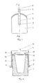
- the ladle in Figures 1 to 4 is equipped with a suspension frame comprising two ladle suspension arms 5, 6 rotatably connected to trunnions 7, 8 fixed to the outside of the ladle 1, and a horizontal beam 9 above the ladle 1.
- the horizontal beam 9 has a hook 10.
- a cover 11 is fixed to the suspension frame either by a first set of pins 12, 13, or alternatively by a second set of pins 14, 15, or both.
- the top of the ladle 1 and the cover 11 are formed as segments of a cylinder, the common axis of these cylinder segments being the pivot axis of the ladle.
- the cover 11 is arranged in such a way that there is a small gap between the top of the ladle 1 and the cover 11.
- the ladle 1 Due to the suspension of the cover 11 and the shape of the cover 11 and the top of ladle 1, the ladle 1 can be freely tilted as shown on Figure 3. In addition, the suspension frame and thereby the cover 11 can be lowered so that the cover 11 will be automatically moved away from the ladle 1 when the ladle 1 is resting on a floor or the like as shown in Figure 4. In this way, molten metal and additives can be charged into the ladle 1.
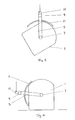
- Figures 5 and 6 show another embodiment of ladle 30 having a suspension frame comprising two ladle suspension arms 31, 32 rotatably connected to trunnions 33, fixed to the outside of the ladle 30, and a horizontal beam 34 above the ladle 30.
- a ladle cover 35 is affixed to the suspension frame in the same way as described above in connection with Figures 1 to 4.
- the top of the ladle 30 and the cover 35 are formed as segments of cylinders, however, the focal axis 36 of these cylinder segments is spaced from the pivot axis of the ladle 30, this pivot axis being the axis connecting the fixing points for the trunnions 33. As shown in Figure 5 and 6 the common focal axis 36 of the cylinder segments is situated to one side of the pivot axis of the ladle 30.
- the cover 35 closes the ladle.
- the ladle 30 can now only be rotated in the direction shown by the arrow 37 in Figures 5 and 6. As soon as the ladle 30 starts to tilt, the top of the ladle 30 will start to move away from the cover 35 and allow free tilting of the ladle. When the ladle 30 is tilted back to its vertical position, the cover 35 will again close the ladle 30.
- the cover of such a ladle may be merely a cover or it may be a cover equipped with a filling basin, commonly referred to as a "tundish".
Landscapes
- Engineering & Computer Science (AREA)
- Chemical & Material Sciences (AREA)
- Mechanical Engineering (AREA)
- Materials Engineering (AREA)
- Metallurgy (AREA)
- Organic Chemistry (AREA)
- Casting Support Devices, Ladles, And Melt Control Thereby (AREA)
- Control And Other Processes For Unpacking Of Materials (AREA)
- Apparatus Associated With Microorganisms And Enzymes (AREA)
- Portable Nailing Machines And Staplers (AREA)
- Table Devices Or Equipment (AREA)
- Food-Manufacturing Devices (AREA)
- Devices For Use In Laboratory Experiments (AREA)
- Sewage (AREA)
- Telephone Function (AREA)
- Magnetic Resonance Imaging Apparatus (AREA)
- Filters For Electric Vacuum Cleaners (AREA)
- Cookers (AREA)
Abstract
Description
- The present invention relates to a tiltable ladle for molten metals and a cover for such a ladle.
- Numerous benefits are available when processing molten metals, if covers are used on the ladles or other molten metal containment and treatment vessels. Where covers are used, there are frequently problems associated with the mechanics of opening and closing the cover to allow metal charging, slag removal etc. These problems can include fouling the mechanics due to metal or slag splashing, time delays in opening and closing the cover, metal spillage if the cover mechanics are rough, and labour intensive operations.
- It is an object of the present invention to provide a ladle and cover which reduces the above problems and in which the cover can be opened and closed automatically when required and also in which the design of the ladle and the cover is simple and reliable.
- According to the invention, there is provided a tiltable ladle assembly comprising a ladle, a cover and a suspension frame, the ladle being pivotally supported by the suspension frame, characterised in that the top of the ladle and the ladle cover are formed as segments of a cylinder, having a common axis, and the cover is affixed to the suspension frame.
- In one form, the common axis of the cylindrical segments coincides with the pivotal axis of the ladle.
- Preferably, the cover is affixed to the suspension frame in such a way that there is a gap between the cover and the ladle.
- In a preferred form, therefore, the present invention may provide a tiltable ladle having a cover and a suspension frame, the suspension frame comprising two lifting arms rotatably connected to trunnions affixed to the outside of the wall of the ladle and a horizontal beam above the ladle equipped with a hook, and in which the top of the ladle and the ladle cover are formed as segments of a cylinder, the focal axis of these cylinder segments being the pivotal axis of the ladle, and in which the cover is affixed to the suspension frame.
- Alternatively, the common axis of these cylindrical segments is spaced at one side of, above, or below the pivot axis of the ladle. Preferably, then, the cover is affixed to the suspension frame in such a way that the cover closes the ladle when the ladle and the suspension arms are in a vertical position.
- Preferably, the suspension frame includes two lifting arms rotatably connected to trunnions affixed to the outside of the wall of the ladle and a beam above the ladle equipped with a hook. The cover may be equipped with a filling basin.
- In another preferred form, therefore, the present invention may provide a tiltable ladle having a cover and a suspension frame, the suspension frame comprising two lifting arms rotatably connected to trunnions affixed to the outside of the wall of the ladle and a horizontal beam above the ladle equipped with a hook, and in which the top of the ladle and the ladle cover are formed as segments of a cylinder, the focal axis of these cylinder segments being placed at one side of, above, at or below the pivot axis of the ladle, the cover being affixed to the suspension frame in such a way that the cover closes the ladle when the ladle and the suspension arms are in a vertical position.
- The invention may be carried into practice in various ways and two embodiments will now be described by way of example with reference to the accompanying drawings in which:
- Figure 1 is a side elevation of ladle and a cover according to a first aspect of the present invention;
- Figure 2 is a cross-section taken along line I-I in Figure 1;
- Figure 3 shows the ladle of Figure 1 in a tilted position;
- Figure 4 shows the ladle of Figure 1 in a vertical position with the suspension frame and cover in a tilted position;
- Figure 5 is a side elevation of a ladle and a cover according to a second aspect of the present invention; and
- Figure 6 shows the ladle of Figure 5 in tilted position.
- The ladle in Figures 1 to 4 is equipped with a suspension frame comprising two
ladle suspension arms trunnions hook 10. A cover 11 is fixed to the suspension frame either by a first set ofpins pins - The top of the ladle 1 and the cover 11 are formed as segments of a cylinder, the common axis of these cylinder segments being the pivot axis of the ladle. As can be seen from Figure 1, the cover 11 is arranged in such a way that there is a small gap between the top of the ladle 1 and the cover 11.
- Due to the suspension of the cover 11 and the shape of the cover 11 and the top of ladle 1, the ladle 1 can be freely tilted as shown on Figure 3. In addition, the suspension frame and thereby the cover 11 can be lowered so that the cover 11 will be automatically moved away from the ladle 1 when the ladle 1 is resting on a floor or the like as shown in Figure 4. In this way, molten metal and additives can be charged into the ladle 1.
- Figures 5 and 6 show another embodiment of
ladle 30 having a suspension frame comprising twoladle suspension arms 31, 32 rotatably connected totrunnions 33, fixed to the outside of theladle 30, and ahorizontal beam 34 above theladle 30. Aladle cover 35 is affixed to the suspension frame in the same way as described above in connection with Figures 1 to 4. - The top of the
ladle 30 and thecover 35 are formed as segments of cylinders, however, thefocal axis 36 of these cylinder segments is spaced from the pivot axis of theladle 30, this pivot axis being the axis connecting the fixing points for thetrunnions 33. As shown in Figure 5 and 6 the commonfocal axis 36 of the cylinder segments is situated to one side of the pivot axis of theladle 30. - When the
ladle suspension arms 31, 32 and theladle 30 are in vertical position, thecover 35 closes the ladle. - The
ladle 30 can now only be rotated in the direction shown by thearrow 37 in Figures 5 and 6. As soon as theladle 30 starts to tilt, the top of theladle 30 will start to move away from thecover 35 and allow free tilting of the ladle. When theladle 30 is tilted back to its vertical position, thecover 35 will again close theladle 30. - The cover of such a ladle may be merely a cover or it may be a cover equipped with a filling basin, commonly referred to as a "tundish".
Claims (7)
Priority Applications (1)
| Application Number | Priority Date | Filing Date | Title |
|---|---|---|---|
| AT89307901T ATE89867T1 (en) | 1988-08-04 | 1989-08-03 | EQUIPMENT FOR A TILT PAN. |
Applications Claiming Priority (2)
| Application Number | Priority Date | Filing Date | Title |
|---|---|---|---|
| NO883455 | 1988-08-04 | ||
| NO883455A NO165016C (en) | 1988-08-04 | 1988-08-04 | TIPPABLE OESE AND LIDS FOR SUCH OESE. |
Publications (3)
| Publication Number | Publication Date |
|---|---|
| EP0354036A2 true EP0354036A2 (en) | 1990-02-07 |
| EP0354036A3 EP0354036A3 (en) | 1990-05-02 |
| EP0354036B1 EP0354036B1 (en) | 1993-05-26 |
Family
ID=19891128
Family Applications (1)
| Application Number | Title | Priority Date | Filing Date |
|---|---|---|---|
| EP89307901A Expired - Lifetime EP0354036B1 (en) | 1988-08-04 | 1989-08-03 | Tiltable ladle assembly |
Country Status (8)
| Country | Link |
|---|---|
| US (1) | US4928862A (en) |
| EP (1) | EP0354036B1 (en) |
| JP (1) | JPH0275464A (en) |
| KR (1) | KR920001711B1 (en) |
| AT (1) | ATE89867T1 (en) |
| DE (2) | DE68906730T4 (en) |
| ES (1) | ES2040467T3 (en) |
| NO (1) | NO165016C (en) |
Families Citing this family (4)
| Publication number | Priority date | Publication date | Assignee | Title |
|---|---|---|---|---|
| KR100471024B1 (en) * | 1996-12-27 | 2005-06-27 | 현대자동차주식회사 | Track guidance system for driverless vehicle |
| JP4896798B2 (en) * | 2007-04-19 | 2012-03-14 | デュプロ精工株式会社 | Paper receiving device for printing machine |
| CN105967042A (en) * | 2016-05-25 | 2016-09-28 | 湖南省金润碲业有限公司 | Lifting and transporting device for metal solution |
| CN114029480A (en) * | 2021-11-19 | 2022-02-11 | 崔荣凯 | Aluminum alloy casting device for metal manufacturing |
Citations (4)
| Publication number | Priority date | Publication date | Assignee | Title |
|---|---|---|---|---|
| DE2601984B1 (en) * | 1976-01-16 | 1977-04-21 | Mannesmann Ag | Crossbar with supports for casting ladle - allowing rapid opening and closing of ladle during transport |
| FR2329389A1 (en) * | 1975-10-29 | 1977-05-27 | Mannesmann Ag | LID ARRANGEMENT FOR CASTING POCKETS OR METALLURGIC TREATMENT CONTAINERS |
| DE3704116A1 (en) * | 1986-03-21 | 1987-09-24 | Inventio Ag | Device for manipulating an inoculating ladle |
| EP0271476A1 (en) * | 1986-11-25 | 1988-06-15 | VOEST-ALPINE INDUSTRIEANLAGENBAU GESELLSCHAFT m.b.H. | Metallurgical vessel with a hinged cover |
Family Cites Families (3)
| Publication number | Priority date | Publication date | Assignee | Title |
|---|---|---|---|---|
| US1624553A (en) * | 1926-06-17 | 1927-04-12 | Hugo Boelter | Ladle |
| US4324392A (en) * | 1980-02-04 | 1982-04-13 | Sandmold Systems, Inc. | Molten metal pouring device |
| US4488711A (en) * | 1983-03-24 | 1984-12-18 | Sperry Corporation | Treating ladle for ductile iron treatment |
-
1988
- 1988-08-04 NO NO883455A patent/NO165016C/en unknown
-
1989
- 1989-06-23 US US07/371,282 patent/US4928862A/en not_active Expired - Fee Related
- 1989-06-30 KR KR1019890009154A patent/KR920001711B1/en not_active IP Right Cessation
- 1989-07-06 JP JP1173151A patent/JPH0275464A/en active Granted
- 1989-08-03 EP EP89307901A patent/EP0354036B1/en not_active Expired - Lifetime
- 1989-08-03 AT AT89307901T patent/ATE89867T1/en not_active IP Right Cessation
- 1989-08-03 DE DE68906730T patent/DE68906730T4/en not_active Expired - Lifetime
- 1989-08-03 DE DE8989307901A patent/DE68906730D1/en not_active Expired - Fee Related
- 1989-08-03 ES ES198989307901T patent/ES2040467T3/en not_active Expired - Lifetime
Patent Citations (4)
| Publication number | Priority date | Publication date | Assignee | Title |
|---|---|---|---|---|
| FR2329389A1 (en) * | 1975-10-29 | 1977-05-27 | Mannesmann Ag | LID ARRANGEMENT FOR CASTING POCKETS OR METALLURGIC TREATMENT CONTAINERS |
| DE2601984B1 (en) * | 1976-01-16 | 1977-04-21 | Mannesmann Ag | Crossbar with supports for casting ladle - allowing rapid opening and closing of ladle during transport |
| DE3704116A1 (en) * | 1986-03-21 | 1987-09-24 | Inventio Ag | Device for manipulating an inoculating ladle |
| EP0271476A1 (en) * | 1986-11-25 | 1988-06-15 | VOEST-ALPINE INDUSTRIEANLAGENBAU GESELLSCHAFT m.b.H. | Metallurgical vessel with a hinged cover |
Also Published As
| Publication number | Publication date |
|---|---|
| JPH0336623B2 (en) | 1991-06-03 |
| EP0354036B1 (en) | 1993-05-26 |
| ES2040467T3 (en) | 1993-10-16 |
| ATE89867T1 (en) | 1993-06-15 |
| DE68906730T4 (en) | 1995-08-31 |
| EP0354036A3 (en) | 1990-05-02 |
| NO883455L (en) | 1990-02-05 |
| KR920001711B1 (en) | 1992-02-24 |
| DE68906730T2 (en) | 1993-10-07 |
| KR900002872A (en) | 1990-03-23 |
| JPH0275464A (en) | 1990-03-15 |
| DE68906730D1 (en) | 1993-07-01 |
| US4928862A (en) | 1990-05-29 |
| NO165016C (en) | 1990-12-12 |
| NO883455D0 (en) | 1988-08-04 |
| NO165016B (en) | 1990-09-03 |
Similar Documents
| Publication | Publication Date | Title |
|---|---|---|
| RU2524035C2 (en) | Bearing head for liquid metal teeming ladle pipe support | |
| US5054033A (en) | Tiltable arc furnace | |
| EP0354036B1 (en) | Tiltable ladle assembly | |
| JPH01244960A (en) | Transfer car for metallurgical transfer vessel | |
| JPS5922926Y2 (en) | Lid equipment for casting ladles or metallurgical processing vessels | |
| US4679205A (en) | Tiltable metallurgical furnace vessel | |
| US4089640A (en) | Furnace hood with integral conveyor feeding | |
| US3930641A (en) | Furnace hood structure | |
| MY111544A (en) | Tilting mechanism for a dc arc furnace and process for discharging of the furnace. | |
| US3047916A (en) | Container-tilting rigging | |
| JPH10502128A (en) | Method and apparatus for directing liquid metal from a tribe to an electric furnace | |
| WO1992002325A1 (en) | Slag control method and apparatus | |
| US4141540A (en) | Hot metal ladle tilter | |
| PL352108A1 (en) | Method of and apparatus for emptying melting metallurgical tanks by tilting | |
| US4256289A (en) | Converter arrangement | |
| ES2023625A4 (en) | PNEUMATIC TANK FOR THE PROCESSING OF STEEL AND METHOD FOR PREPARING STEEL | |
| US3784178A (en) | Tiltable foundry converter for treatment and storage of molten metal | |
| US4940215A (en) | Tiltable ladle with lid | |
| KR810002506Y1 (en) | Tilting devices for ladle | |
| SU424656A1 (en) | BUCKET FOR STALIUM TRANSPORTATION: 1FSH1D v ;;: ai — yyyrg — g ~~ " | |
| SU1488124A1 (en) | Steel-teeming ladle | |
| JPS59225879A (en) | Casting system | |
| JPS6041512Y2 (en) | Steel tapping equipment | |
| JPS6214118Y2 (en) | ||
| IT1260558B (en) | Temperature measuring and sampling device for an electric furnace |
Legal Events
| Date | Code | Title | Description |
|---|---|---|---|
| PUAI | Public reference made under article 153(3) epc to a published international application that has entered the european phase |
Free format text: ORIGINAL CODE: 0009012 |
|
| AK | Designated contracting states |
Kind code of ref document: A2 Designated state(s): AT BE CH DE ES FR GB GR IT LI LU NL SE |
|
| PUAL | Search report despatched |
Free format text: ORIGINAL CODE: 0009013 |
|
| AK | Designated contracting states |
Kind code of ref document: A3 Designated state(s): AT BE CH DE ES FR GB GR IT LI LU NL SE |
|
| 17P | Request for examination filed |
Effective date: 19901009 |
|
| 17Q | First examination report despatched |
Effective date: 19920722 |
|
| GRAA | (expected) grant |
Free format text: ORIGINAL CODE: 0009210 |
|
| ITF | It: translation for a ep patent filed |
Owner name: BARZANO' E ZANARDO MILANO S.P.A. |
|
| AK | Designated contracting states |
Kind code of ref document: B1 Designated state(s): AT BE CH DE ES FR GB GR IT LI LU NL SE |
|
| PG25 | Lapsed in a contracting state [announced via postgrant information from national office to epo] |
Ref country code: LI Effective date: 19930526 Ref country code: GR Free format text: LAPSE BECAUSE OF FAILURE TO SUBMIT A TRANSLATION OF THE DESCRIPTION OR TO PAY THE FEE WITHIN THE PRESCRIBED TIME-LIMIT Effective date: 19930526 Ref country code: CH Effective date: 19930526 Ref country code: AT Effective date: 19930526 |
|
| REF | Corresponds to: |
Ref document number: 89867 Country of ref document: AT Date of ref document: 19930615 Kind code of ref document: T |
|
| REF | Corresponds to: |
Ref document number: 68906730 Country of ref document: DE Date of ref document: 19930701 |
|
| ET | Fr: translation filed | ||
| PG25 | Lapsed in a contracting state [announced via postgrant information from national office to epo] |
Ref country code: LU Free format text: LAPSE BECAUSE OF NON-PAYMENT OF DUE FEES Effective date: 19930831 |
|
| REG | Reference to a national code |
Ref country code: CH Ref legal event code: PL |
|
| REG | Reference to a national code |
Ref country code: ES Ref legal event code: FG2A Ref document number: 2040467 Country of ref document: ES Kind code of ref document: T3 |
|
| PLBE | No opposition filed within time limit |
Free format text: ORIGINAL CODE: 0009261 |
|
| STAA | Information on the status of an ep patent application or granted ep patent |
Free format text: STATUS: NO OPPOSITION FILED WITHIN TIME LIMIT |
|
| 26N | No opposition filed | ||
| PGFP | Annual fee paid to national office [announced via postgrant information from national office to epo] |
Ref country code: GB Payment date: 19940726 Year of fee payment: 6 |
|
| PGFP | Annual fee paid to national office [announced via postgrant information from national office to epo] |
Ref country code: FR Payment date: 19940729 Year of fee payment: 6 |
|
| PGFP | Annual fee paid to national office [announced via postgrant information from national office to epo] |
Ref country code: ES Payment date: 19940805 Year of fee payment: 6 |
|
| PGFP | Annual fee paid to national office [announced via postgrant information from national office to epo] |
Ref country code: DE Payment date: 19940822 Year of fee payment: 6 |
|
| PGFP | Annual fee paid to national office [announced via postgrant information from national office to epo] |
Ref country code: BE Payment date: 19940829 Year of fee payment: 6 |
|
| PGFP | Annual fee paid to national office [announced via postgrant information from national office to epo] |
Ref country code: SE Payment date: 19940831 Year of fee payment: 6 Ref country code: NL Payment date: 19940831 Year of fee payment: 6 |
|
| EAL | Se: european patent in force in sweden |
Ref document number: 89307901.2 |
|
| PG25 | Lapsed in a contracting state [announced via postgrant information from national office to epo] |
Ref country code: GB Effective date: 19950803 |
|
| PG25 | Lapsed in a contracting state [announced via postgrant information from national office to epo] |
Ref country code: SE Effective date: 19950804 Ref country code: ES Free format text: LAPSE BECAUSE OF EXPIRATION OF PROTECTION Effective date: 19950804 |
|
| PG25 | Lapsed in a contracting state [announced via postgrant information from national office to epo] |
Ref country code: BE Effective date: 19950831 |
|
| BERE | Be: lapsed |
Owner name: ELKEM A/S Effective date: 19950831 |
|
| PG25 | Lapsed in a contracting state [announced via postgrant information from national office to epo] |
Ref country code: NL Effective date: 19960301 |
|
| GBPC | Gb: european patent ceased through non-payment of renewal fee |
Effective date: 19950803 |
|
| PG25 | Lapsed in a contracting state [announced via postgrant information from national office to epo] |
Ref country code: FR Effective date: 19960430 |
|
| NLV4 | Nl: lapsed or anulled due to non-payment of the annual fee |
Effective date: 19960301 |
|
| PG25 | Lapsed in a contracting state [announced via postgrant information from national office to epo] |
Ref country code: DE Effective date: 19960501 |
|
| EUG | Se: european patent has lapsed |
Ref document number: 89307901.2 |
|
| REG | Reference to a national code |
Ref country code: FR Ref legal event code: ST |
|
| REG | Reference to a national code |
Ref country code: ES Ref legal event code: FD2A Effective date: 19990601 |
|
| PG25 | Lapsed in a contracting state [announced via postgrant information from national office to epo] |
Ref country code: IT Free format text: LAPSE BECAUSE OF NON-PAYMENT OF DUE FEES;WARNING: LAPSES OF ITALIAN PATENTS WITH EFFECTIVE DATE BEFORE 2007 MAY HAVE OCCURRED AT ANY TIME BEFORE 2007. THE CORRECT EFFECTIVE DATE MAY BE DIFFERENT FROM THE ONE RECORDED. Effective date: 20050803 |