EP0353881B1 - Machine for operating progressively along marginal portions of shoes - Google Patents
Machine for operating progressively along marginal portions of shoes Download PDFInfo
- Publication number
- EP0353881B1 EP0353881B1 EP19890307022 EP89307022A EP0353881B1 EP 0353881 B1 EP0353881 B1 EP 0353881B1 EP 19890307022 EP19890307022 EP 19890307022 EP 89307022 A EP89307022 A EP 89307022A EP 0353881 B1 EP0353881 B1 EP 0353881B1
- Authority
- EP
- European Patent Office
- Prior art keywords
- tool
- shoe
- movement
- ball
- support
- Prior art date
- Legal status (The legal status is an assumption and is not a legal conclusion. Google has not performed a legal analysis and makes no representation as to the accuracy of the status listed.)
- Expired - Lifetime
Links
Images


Classifications
-
- A—HUMAN NECESSITIES
- A43—FOOTWEAR
- A43D—MACHINES, TOOLS, EQUIPMENT OR METHODS FOR MANUFACTURING OR REPAIRING FOOTWEAR
- A43D119/00—Driving or controlling mechanisms of shoe machines; Frames for shoe machines
-
- A—HUMAN NECESSITIES
- A43—FOOTWEAR
- A43D—MACHINES, TOOLS, EQUIPMENT OR METHODS FOR MANUFACTURING OR REPAIRING FOOTWEAR
- A43D25/00—Devices for gluing shoe parts
- A43D25/18—Devices for applying adhesives to shoe parts
- A43D25/183—Devices for applying adhesives to shoe parts by nozzles
-
- B—PERFORMING OPERATIONS; TRANSPORTING
- B05—SPRAYING OR ATOMISING IN GENERAL; APPLYING FLUENT MATERIALS TO SURFACES, IN GENERAL
- B05C—APPARATUS FOR APPLYING FLUENT MATERIALS TO SURFACES, IN GENERAL
- B05C1/00—Apparatus in which liquid or other fluent material is applied to the surface of the work by contact with a member carrying the liquid or other fluent material, e.g. a porous member loaded with a liquid to be applied as a coating
Definitions
- This invention is concerned with a method of operating progressively along marginal portions of shoes using a machine which comprises a shoe support for supporting a lasted shoe with marginal portions thereof exposed and a tool support for supporting a tool for effecting an operation on such marginal portions, wherein relative movement can take place between the shoe support and the tool support in directions extending both lengthwise and widthwise of the shoe bottom, whereby the tool can effect an operation progressively along the marginal portions of the shoe.
- EP-A-0276944 being a method of applying adhesive progressively to marginal portions of shoe bottoms.
- the tool is constituted by a rotary brush which surrounds a nozzle outlet through which adhesive is supplied, the arrangement being such that, as the tool is caused to operate progressively along the shoe bottom, the rotating brush serves to spread the adhesive, giving a clearly defined edge adjacent to the edge of the shoe bottom.
- a seam is provided, e.g. between the vamp and the quarter of the shoe, which is stitched.
- the roughing brush breaks the stitches, with a result that while the underlying portion in the region of overlap remains adhered to the insole of the shoe, the top portion in such region, previously held in position by the stitching, is now loose.
- a subsequent adhesive-applying operation therefore, where such top portion is "downstream" of the Vietnamesewhile seam (in terms of the direction of movement of the tool relative to the shoe bottom) there is a tendency for the tool to lift such top portion and fold it back upon itself.
- the tool tends to break the adhesion between the lasting margin of the upper and the insole.
- the direction of relative lengthwise movement between the tool and the marginal portion of the shoe being operated upon may be reversed in the region of any overlap in order to ensure that the top portion in the region of the overlap lies "upstream" of the occidentalle seam in terms of the direction of relative lengthwise movement over said marginal portion.
- the action of the tool in each case is effective to press the top portion against the underlying portion and thus retain the two portions in the desired relationship.
- the direction of relative lengthwise movement for a particular marginal portion there is no risk of the tool lifting the top portion and folding it back upon itself, still less of effecting a de-lasting action.
- the tool is constituted by an adhesive-applying tool comprising a nozzle having a housing in which a ball is accommodated for controlling the flow of adhesive through the housing and which has an end face providing an annular rim by which the ball is retained in the housing but which allows a portion of the ball to project beyond said end face, spring means being provided for urging the ball into a sealing position against the annular rim, thus to prevent the flow of adhesive from the nozzle, but the ball being movable against the spring pressure out of such sealing position, thus to allow adhesive flow, such movement of the ball being limited by an abutment such that a portion of the ball still projects beyond the end face of the housing.
- an adhesive-applying tool of this type is of course of particular benefit in that the adhesive flow is automatically shut off each time the ball of the tool and the marginal portion of the shoe move out of operative contact with one another.
- the invention has been found particularly useful, moreover, where the adhesive-applying tool further comprises a brush assembly rotatable about an axis extending lengthwise of the nozzle for spreading adhesive supplied from the nozzle, and comprising bristles which extend in a direction lengthwise of the nozzle housing and are disposed about the whole of the periphery of said end face, and which project beyond said end face by a distance which can be set, drive means being provided for effecting such rotation of the brush assembly.
- the machine thus comprises a base (10) supporting, by a bracket (12), a pivot shaft (14) about which a support (16) for a shoe support (18) can pivot.
- the shoe support is arranged to support a shoe (S) bottom uppermost, with the toe end thereof facing towards the front of the machine, i.e. towards the operator.
- the base (10) supports a support column structure (22) carrying a casting (24) on which is supported, for pivotal movement about a vertical axis, a support casting 34 having two upstanding lugs 32 between which a tool support generally designated 26' is supported for pivotal movement about a horizontal axis 31.
- the machine further comprises a first stepping motor (144) mounted on the base (10) and effective to cause pivotal movement of the shoe support (18) to take place about the horizontal axis provided by the shaft (14) (X-axis movement).
- a second stepping motor (84) is provided, carried by the casting (24) and effective to cause pivotal movement of the support casting 34 about its vertical axis (Y-axis movement).
- a third stepping motor (122 - described in EP-A-0043645) is supported by the support casting 34, rearwardly of its vertical pivot, to cause it, and thus the tool support means 26' supported thereby, to pivot about its horizontal axis 31 (Z-axis movement).
- the X-, Y- and Z-axes represent three co-ordinate axes along which a tool supported by the tool supporting means 26' can move.
- Details of the shoe support (18) can be found in GB-A-2077090, and further details of the construction by which movement along the three axes can take place can be found in EP-A-0091321 and also in EP-A-0043645.
- the tool support 26' comprises a housing 650 mounted for pivotal movement about said horizontal axis 31. From a forward face of the housing projects a hollow, tubular arm 652 within which is accommodated, for rotational movement therein, a support rod 654. At the forward end of said rod is a plate 656 supporting two forwardly projecting arms 658, which are spaced apart widthwise of the machine and on each of which is mounted, for pivotal movement, a pair of links 660, 662, upper ends of which pivotally support a plate 664.
- the links 660, 662, together with the plate 664 and arms 658, thus comprise a first parallel linkage arrangement of the tool supporting means.
- a further plate 666 Fixedly secured to a forward end of the plate 664, and projecting forwardly therefrom, is a further plate 666, in a forward, bifurcated, end of which is pivotally mounted a block 668 forming part of a tool holder generally designated 670. Also secured to the tool holder, at the left-hand side thereof, is a further link 672 which is in turn pivotally connected to each of the left-hand links 660, 662.
- the links 660, 662, tool holder 670, link 672 and composite plate 664, 666 thus constitute a second parallel linkage of the tool supporting means.
- the various pivots are so arranged in relation to one another that the tool holder is caused to pivot about an axis (a virtual centre) extending transversely of the bottom of a shoe supported by the shoe support (18) and passing through a point P, which lies on the axis of the support rod 654.
- a point P which lies on the axis of the support rod 654.
- the point P represents a height datum of the machine in a desired relationship with which the bottom of a shoe supported by the shoe support (18) can be positioned by means of a holddown member (450) and toe support means (470) of said support.
- the point P lies vertically above the axis (14) of the shoe support (18).
- the links 662 carry therebetween a block 674 to which is pivotally connected a forward end of a push-rod 676, the rearward end of which is similarly pivotally connected to a block 678 which is mounted on a pulley 680 freely rotatable about a drive shaft 682.
- the pulley 680 is caused to rotate about said shaft by a timing belt 684 entrained around a second pulley 688, a tensioning pulley 690 being provided for maintaining the tension in the belt.
- a third pulley 692 around which is entrained a second timing belt 694 meshing with a fourth, drive, pulley 696 secured on the drive shaft 682.
- the shaft 682 is driven by a stepping motor 698.
- a similar drive arrangement comprising a stepping motor 700 acting through pulleys 702, 704, 706 (the fourth not being shown) and timing belts (not shown), the pulley 706 being fixedly mounted on the support rod 654.
- the tool holder 670 is arranged to support a tool generally designated 250 in the form of an adhesive applicator device generally as described in EP-A-0276944, the tool being fixedly mounted in the block 668.
- the mounting arrangement is generally similar to the alternative mounting arrangement referred to in the aforementioned specification.
- the adhesive applicator device 250 thus comprises a hollow shaft 366 (Fig. 2) mounted in the block 668 and carrying at its lower end a sprocket 368 pivotally connected by a chain (not shown but numbered 386 in said specification) to an electric motor also carried on the tool holder 670.
- the shaft 366 carries a collar 370 in which is secured an upstanding pin 372 accommodated in a bore 374 of a further collar 376 which is threadedly secured to an output end 378 of a rotary coupling generally designated 380.
- Force-fitted into the collar 376 is the upper end of an adhesive supply tube 382 which passes through the hollow shaft 366 and has screw-threaded on the lower end thereof a nozzle housing 384 (see Figs. 3 and 4). It will thus be appreciated that rotation of the sprocket 368 causes, through the pin 372 and bore 374, rotation of the tube 382 and thus of the nozzle housing 384 secured thereto.
- the nozzle housing 384 has a frustoconical lower end face 384 a which provides an annular rim spaced from the lower end face 382 a of the tube 382 to form therein a chamber in which a ball 392 is accommodated with a portion thereof projecting beyond the annular rim.
- a spring 394 is accommodated in a counter-sink formed in the lower end of the tube 382 and urges the ball against the annular rim into a sealing position in which adhesive flow through the nozzle is prevented.
- pressing the ball 392 against a component to be coated with adhesive causes the ball to retract, to allow adhesive to be supplied through the nozzle, the supply continuing until the ball is moved out of contact with the component whereupon sealing takes place substantially immediately with consequent cut-off of the adhesive.
- the ball is shown in its retracted condition in Fig. 4.
- the nozzle housing 384 is capable of "floating" relative to the bearing block 364, that is to say excessive pressure applied to the ball is accommodated by sliding movement of the nozzle housing bodily in relation to the hollow shaft 366, so that any irregularities in the surface of the shoe bottom to be coated with adhesive, in relation to the heightwise path as determined by the third n.c. motor (122), can be accommodated.
- a further spring 396 is provided acting between the nozzle housing and the underside of the hollow shaft, the force applied by the spring 396 being significantly greater than that applied by the spring 394, so as to ensure that the ball will first retract when engaged.
- the operative surface portion of the tool is set at the point P, that is to say a certain amount of the "float” is taken up during teaching, thereby allowing variations of a plus or minus value from that position to take place according to any irregularities in the contour of the shoe bottom.
- the operator when the machine is in its "teaching" mode, has regard to the distance between the two collars 370, 376. If desired, furthermore, a scale may be provided on one of the collars to assist the operator.
- a brush assembly generally designated 398 is secured to the outside of the nozzle housing 384, e.g. by a Jubilee clip 400.
- the brush assembly 398 comprises a ring 402, e.g. of plastics material, which is slid along the nozzle housing and in which are embedded sets of bristles 404 arranged to form a cylindrical shape which surrounds the nozzle housing and projects beyond the end face 384 a , being disposed about the whole of the periphery of said end face 38 4 a.
- the machine has a "teaching" mode as well as an “operating” mode.
- operator-actuatable means in the form of a cursor arrangement (not shown) or a joystick control (also not shown) is provided whereby the path of movement of the tool can be determined; the particular path determination procedure is described in detail in US-A4541054.
- the machine For the digitising procedure itself and also for controlling the operation of the machine in its operating mode the machine also comprises computer control means.
- This means comprises a memory in which a number of programmed instructions can be stored for different styles of shoe and also in which a number of sub-routines are stored for processing the data relating to the various styles. Thus one such sub-routine serves to determine the path the tool will follow, based upon the digitised points.
- a further sub-routine is a grading programme which, according to the shoe length, as "measured” by the shoe support (18) (details of the shoe length measuring arrangement are described in GB-A2077090), is effective correspondingly to vary the distance between successive digitised points along the X-axis and also proportionately to vary the Y-axis movement, such variation of the Y-axis movement also serving to vary the incidence of the Z-axis movement and the pivotal movement about the first and second axes ('camber' and 'tilt' movement) of the tool holder 670.
- Such change in the direction of the tool movement can be achieved during the "teaching" mode of operation of the machine in the following manner: after the "teaching" of a point P1 which lies “upstream” of a seam and spaced therefrom by at least the distance between successive points (which is of course predetermined), and with the tool moved to its next start position along the X- and Z-axes as aforesaid, the operator again actuates the "teach” button (642) thereby effectively “teaching” a point P2 which is in space.
- the operator must also take into account the fact that the tool "floats" and must ensure that the tool is in fact clear of the shoe bottom even when the operative surface of the tool is urged downwardly by the spring 396 as aforesaid. If in fact the next start position is such that the ball is in contact with the shoe bottom, then clearly the operator must, through the operator-actuatable means, effect sufficient Z-axis movement to ensure that the tool and shoe bottom are moved out of operative contact prior to actuation of the "teach" button.
- this procedure is preferably repeated for a second point P3 whereafter the next point P4 will be digitised and "taught" in the usual manner, that is to say with the tool and shoe support in operative contact.
- the next point P5 to be digitised is then effected in the reverse direction, i.e. back towards the seam, and the digitising of points P6, P7 in a reverse direction continues to be effected until a position is reached beyond the seam, which is coincident with or overlaps the last point P1 to be digitised in the first direction of movement of the tool , at which point operative contact was maintained between the tool and the shoe bottom.
- the reversal of the direction of movement of the tool need only be effected on the side of the shoe where, in terms of the first direction of movement of the tool need only be effected on the side of the shoe where, in terms of the first direction of movement of the tool, the top portion of the overlap is disposed "downstream" of the seam.
- the operator may select whether to effect two separate reverse movements of the tool or a single reverse movement, according to the spacing of the seams.
- a sub-programme may be provided whereby the operator merely digitises the shoe bottom in the usual manner, but at the first point "downstream" of a seam, that is to say, immediately after the seam has been passed during the digitising process, the operator may activate the sub-programme whereby automatically a procedure generally as set out above, including points in space, can be effected as part of the digitising process, but without physically moving the tool in a reverse direction, so that a similar effect can be achieved in the operating mode of the machine.
- a facility could be provided whereby, in the teaching mode of the machine, a signal can be supplied by the operator before a seam is reached, but otherwise digitising takes place in the usual manner, the effect of the signal being that the next succeeding points are interpreted by a sub-routine of a computer programme to effect the movement through space and reverse movement with the tool and shoe bottom in operative contact, followed by further movement in space in the manner described above.
- marginal portions of shoes with broken seams can readily be treated, e.g.. by way of the application of adhesive to such marginal portions, without the detrimental effect which has been experienced where the direction of movement of the tool in relation to the shoe bottom cannot be reversed in those regions.
- the invention has been described hereinbefore with reference to the application of adhesive to marginal portions of shoe bottoms, it would also be applicable to the control of the roughing of marginal portions of shoe bottoms and other operations thereon and also to various operations to be performed on the side wall portions of shoes.
Description
- This invention is concerned with a method of operating progressively along marginal portions of shoes using a machine which comprises a shoe support for supporting a lasted shoe with marginal portions thereof exposed and a tool support for supporting a tool for effecting an operation on such marginal portions, wherein relative movement can take place between the shoe support and the tool support in directions extending both lengthwise and widthwise of the shoe bottom, whereby the tool can effect an operation progressively along the marginal portions of the shoe.
- One such method is disclosed in EP-A-0276944, being a method of applying adhesive progressively to marginal portions of shoe bottoms. In this case, the tool is constituted by a rotary brush which surrounds a nozzle outlet through which adhesive is supplied, the arrangement being such that, as the tool is caused to operate progressively along the shoe bottom, the rotating brush serves to spread the adhesive, giving a clearly defined edge adjacent to the edge of the shoe bottom.
- In some styles of shoe a seam is provided, e.g. between the vamp and the quarter of the shoe, which is stitched. In carrying out a roughing operation on marginal portions of the bottom of such a shoe, it is sometimes found that the roughing brush breaks the stitches, with a result that while the underlying portion in the region of overlap remains adhered to the insole of the shoe, the top portion in such region, previously held in position by the stitching, is now loose. In carrying out a subsequent adhesive-applying operation, therefore, where such top portion is "downstream" of the erstwhile seam (in terms of the direction of movement of the tool relative to the shoe bottom) there is a tendency for the tool to lift such top portion and fold it back upon itself. In particularly bad cases, furthermore, there is a tendency for the tool to de-last the upper starting at such overlap region; that is to say, the tool tends to break the adhesion between the lasting margin of the upper and the insole.
- It will of course be appreciated that where the top portion in the region of the overlap is "upstream" of the erstwhile seam (in terms of the direction of relative movement between the tool and the shoe bottom), there is no significant tendency to dislodge the now loose top portion. In the case of a shoe having only a single seam on each side thereof, therefore, the problem will arise only as the tool tracks along one side, depending on the particular overlap. In some shoes, however, the problem may be exacerbated in that two oppositely facing overlaps may be provided, e.g. between a toe cap and the vamp on the one hand, and the quarter and the vamp on the other. In such cases, the problem will thus arise at each side of the shoe.
- Whereas the problem set out above relates to an adhesive-applying operation which follows a prior roughing operation, it will be appreciated that in the roughing operation itself also there could be a tendency to dislodge the top portion in the region of the overlap, with consequent detriment to the quality of roughing and even damage to the shoe, and the same problem can be envisaged in carrying out other peripheral operations on shoe bottoms. Similarly the same problem may also arise where side wall portions of shoes are or have been roughed.
- It is thus the object of the present invention to provide an improved method of operating progressively along marginal portions of shoes in which the above problem can be avoided.
- This object is resolved, in accordance with the present invention, in a method as set out in the first paragraph above, in that, during such progressive operation for a selected marginal portion of the shoe relative heightwise movement of separation is effected between the shoe support and the tool support to cause the tool and such marginal portion to be moved out of operative contact with one another while relative lengthwise movement is taking place in a first direction, and thereafter relative heightwise movement of approach is effected between the shoe support and the tool support to return said marginal portion and the tool into such operative contact and the direction of relative lengthwise movement is reversed whereby the tool is caused to operate progressively along said marginal portion in a reverse direction, at the end of which operation the direction of the relative lengthwise movement is once more reversed and thus continues in said first direction.
- It will thus be appreciated that, in using the method in accordance with the invention, the direction of relative lengthwise movement between the tool and the marginal portion of the shoe being operated upon may be reversed in the region of any overlap in order to ensure that the top portion in the region of the overlap lies "upstream" of the erstwhile seam in terms of the direction of relative lengthwise movement over said marginal portion. In this way, the action of the tool in each case is effective to press the top portion against the underlying portion and thus retain the two portions in the desired relationship. In particular, by correctly determining the direction of relative lengthwise movement for a particular marginal portion, there is no risk of the tool lifting the top portion and folding it back upon itself, still less of effecting a de-lasting action.
- In carrying out such method, moreover, preferably as the direction of the relative lengthwise movement is once more reversed as aforesaid, relative heightwise movement of separation is once more effected between the shoe support and the tool support for said selected marginal portion, relative heightwise movement of approach thereafter being effected to restore the operative contact between the shoe and the tool and thus to enable the tool to continue its progressive operation in said first direction. In this way it can be ensured that the top portion is not in fact dislodged after the particular operation has been completed, and in addition the duplication of the operation can be avoided. This is of course particularly important when the operation involves the application of adhesive, since excessive adhesive may result in an unsightly appearance to the finished shoe, and again in the case of a roughing operation, when excessive roughing could damage the lasting margin.
- In one embodiment of the invention, the tool is constituted by an adhesive-applying tool comprising a nozzle having a housing in which a ball is accommodated for controlling the flow of adhesive through the housing and which has an end face providing an annular rim by which the ball is retained in the housing but which allows a portion of the ball to project beyond said end face, spring means being provided for urging the ball into a sealing position against the annular rim, thus to prevent the flow of adhesive from the nozzle, but the ball being movable against the spring pressure out of such sealing position, thus to allow adhesive flow, such movement of the ball being limited by an abutment such that a portion of the ball still projects beyond the end face of the housing. An adhesive-applying tool of this type is of course of particular benefit in that the adhesive flow is automatically shut off each time the ball of the tool and the marginal portion of the shoe move out of operative contact with one another. The invention has been found particularly useful, moreover, where the adhesive-applying tool further comprises a brush assembly rotatable about an axis extending lengthwise of the nozzle for spreading adhesive supplied from the nozzle, and comprising bristles which extend in a direction lengthwise of the nozzle housing and are disposed about the whole of the periphery of said end face, and which project beyond said end face by a distance which can be set, drive means being provided for effecting such rotation of the brush assembly.
- The above and other features of the invention will become clearer from the following detailed description, to be read with reference to the accompanying drawings, of one method in accordance with the invention. It will of course be appreciated that this method has been selected for description merely by way of non-limiting example.
- In the accompanying drawings:-
- Fig. 1 is a view in side elevation of a tool support of a machine for carrying out the method in accordance with the invention, said support supporting an adhesive-applying tool arranged and adapted for use in applying adhesive to marginal portions of shoe bottoms;
- Fig. 2 is a fragmentary view, partly in section, showing details of the tool shown in Fig. 1;
- Figs. 3 and 4 are fragmentary views showing a ball of the tool shown in Fig. 2, respectively in its sealing position and moved out of said position by engagement with a shoe bottom; and
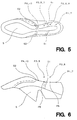
- Figs. 5 and 6 are respectively plan and side views of a shoe and indicate the manner in which control of relative lengthwise movement between the shoe bottom and the tool is achieved.
- The machine in which the method now to be described is to be carried out is generally similar, except as hereinafter described, to the machine described in EP-A-0091321, itself a modification of the apparatus described in EP-A-0043645, which machine is for performing a roughing operation progressively along marginal portions of a shoe bottom. It will however be appreciated that the machine described hereinafter is a machine for performing a cementing (i.e. adhesive-applying) operation progressively along marginal portions of a shoe bottom. Reliance is thus placed upon the disclosure of the aforementioned EP specification and in particular, where like parts are incorporated in the two machines but are not shown in the drawings of the present specification, the reference numerals from the earlier specification are used, but are placed in brackets to indicate that the parts are not shown in the present drawings.
- The machine thus comprises a base (10) supporting, by a bracket (12), a pivot shaft (14) about which a support (16) for a shoe support (18) can pivot. The shoe support is arranged to support a shoe (S) bottom uppermost, with the toe end thereof facing towards the front of the machine, i.e. towards the operator. At its rear, the base (10) supports a support column structure (22) carrying a casting (24) on which is supported, for pivotal movement about a vertical axis, a
support casting 34 having twoupstanding lugs 32 between which a tool support generally designated 26' is supported for pivotal movement about ahorizontal axis 31. - The machine further comprises a first stepping motor (144) mounted on the base (10) and effective to cause pivotal movement of the shoe support (18) to take place about the horizontal axis provided by the shaft (14) (X-axis movement). Similarly, a second stepping motor (84) is provided, carried by the casting (24) and effective to cause pivotal movement of the
support casting 34 about its vertical axis (Y-axis movement). In addition, a third stepping motor (122 - described in EP-A-0043645) is supported by thesupport casting 34, rearwardly of its vertical pivot, to cause it, and thus the tool support means 26' supported thereby, to pivot about its horizontal axis 31 (Z-axis movement). It will be appreciated that the X-, Y- and Z-axes represent three co-ordinate axes along which a tool supported by the tool supporting means 26' can move. Details of the shoe support (18) can be found in GB-A-2077090, and further details of the construction by which movement along the three axes can take place can be found in EP-A-0091321 and also in EP-A-0043645. - The tool support 26' comprises a
housing 650 mounted for pivotal movement about saidhorizontal axis 31. From a forward face of the housing projects a hollow,tubular arm 652 within which is accommodated, for rotational movement therein, asupport rod 654. At the forward end of said rod is aplate 656 supporting two forwardly projectingarms 658, which are spaced apart widthwise of the machine and on each of which is mounted, for pivotal movement, a pair oflinks plate 664. Thelinks plate 664 andarms 658, thus comprise a first parallel linkage arrangement of the tool supporting means. - Fixedly secured to a forward end of the
plate 664, and projecting forwardly therefrom, is afurther plate 666, in a forward, bifurcated, end of which is pivotally mounted ablock 668 forming part of a tool holder generally designated 670. Also secured to the tool holder, at the left-hand side thereof, is afurther link 672 which is in turn pivotally connected to each of the left-hand links links tool holder 670,link 672 andcomposite plate support rod 654. As will be described hereinafter, furthermore, when a tool is supported in thetool holder 670, the axis of rotation thereof also passes through said point P. The point P represents a height datum of the machine in a desired relationship with which the bottom of a shoe supported by the shoe support (18) can be positioned by means of a holddown member (450) and toe support means (470) of said support. Furthermore, in a central position of the tool supporting means 26 the point P lies vertically above the axis (14) of the shoe support (18). - For effecting such pivotal, or tilting, movement of the
tool holder 670 about the transverse axis, thelinks 662 carry therebetween ablock 674 to which is pivotally connected a forward end of a push-rod 676, the rearward end of which is similarly pivotally connected to ablock 678 which is mounted on apulley 680 freely rotatable about adrive shaft 682. Thepulley 680 is caused to rotate about said shaft by atiming belt 684 entrained around asecond pulley 688, atensioning pulley 690 being provided for maintaining the tension in the belt. Also mounted on theshaft 688 is athird pulley 692 around which is entrained asecond timing belt 694 meshing with a fourth, drive,pulley 696 secured on thedrive shaft 682. Theshaft 682 is driven by a steppingmotor 698. - For effecting rotational movement of the
support rod 654, a similar drive arrangement is provided comprising a steppingmotor 700 acting throughpulleys pulley 706 being fixedly mounted on thesupport rod 654. - The
tool holder 670 is arranged to support a tool generally designated 250 in the form of an adhesive applicator device generally as described in EP-A-0276944, the tool being fixedly mounted in theblock 668. (The mounting arrangement is generally similar to the alternative mounting arrangement referred to in the aforementioned specification.) The adhesive applicator device 250 thus comprises a hollow shaft 366 (Fig. 2) mounted in theblock 668 and carrying at its lower end asprocket 368 pivotally connected by a chain (not shown but numbered 386 in said specification) to an electric motor also carried on thetool holder 670. At its upper end theshaft 366 carries acollar 370 in which is secured anupstanding pin 372 accommodated in abore 374 of afurther collar 376 which is threadedly secured to anoutput end 378 of a rotary coupling generally designated 380. Force-fitted into thecollar 376, furthermore, is the upper end of anadhesive supply tube 382 which passes through thehollow shaft 366 and has screw-threaded on the lower end thereof a nozzle housing 384 (see Figs. 3 and 4). It will thus be appreciated that rotation of thesprocket 368 causes, through thepin 372 and bore 374, rotation of thetube 382 and thus of thenozzle housing 384 secured thereto. - The
nozzle housing 384 has a frustoconicallower end face 384a which provides an annular rim spaced from thelower end face 382a of thetube 382 to form therein a chamber in which aball 392 is accommodated with a portion thereof projecting beyond the annular rim. Aspring 394 is accommodated in a counter-sink formed in the lower end of thetube 382 and urges the ball against the annular rim into a sealing position in which adhesive flow through the nozzle is prevented. The application of pressure to the projecting portion of theball 392, on the other hand, causes it to retract against thelower end 382a of said counter-sink, which is slotted so as to allow adhesive flow from the tube when the ball is urged thereagainst, such adhesive then flowing over the surface of the ball and out between the annular rim and the projecting portion of the ball. - It will thus be appreciated that, in using the device 250, pressing the
ball 392 against a component to be coated with adhesive causes the ball to retract, to allow adhesive to be supplied through the nozzle, the supply continuing until the ball is moved out of contact with the component whereupon sealing takes place substantially immediately with consequent cut-off of the adhesive. The ball is shown in its retracted condition in Fig. 4. - The
nozzle housing 384 is capable of "floating" relative to thebearing block 364, that is to say excessive pressure applied to the ball is accommodated by sliding movement of the nozzle housing bodily in relation to thehollow shaft 366, so that any irregularities in the surface of the shoe bottom to be coated with adhesive, in relation to the heightwise path as determined by the third n.c. motor (122), can be accommodated. To ensure that the nozzle housing is urged into its lowered position, afurther spring 396 is provided acting between the nozzle housing and the underside of the hollow shaft, the force applied by thespring 396 being significantly greater than that applied by thespring 394, so as to ensure that the ball will first retract when engaged. As can be seen from Fig. 1, when the housing is in its lowermost position it lies below the point P. In a "teaching" mode of operation of the machine (referred to hereinafter), in setting the Z-axis position desirably the operative surface portion of the tool is set at the point P, that is to say a certain amount of the "float" is taken up during teaching, thereby allowing variations of a plus or minus value from that position to take place according to any irregularities in the contour of the shoe bottom. Conveniently for determining the amount of float, the operator, when the machine is in its "teaching" mode, has regard to the distance between the twocollars - For spreading the adhesive which is supplied through the nozzle, a brush assembly generally designated 398 is secured to the outside of the
nozzle housing 384, e.g. by aJubilee clip 400. Thebrush assembly 398 comprises aring 402, e.g. of plastics material, which is slid along the nozzle housing and in which are embedded sets ofbristles 404 arranged to form a cylindrical shape which surrounds the nozzle housing and projects beyond theend face 384a, being disposed about the whole of the periphery of saidend face 384a. By virtue of its being fixed to the housing as aforesaid, thebrush assembly 398 rotates with thenozzle housing 384. - As already mentioned, the machine has a "teaching" mode as well as an "operating" mode. For the purpose of the former, operator-actuatable means in the form of a cursor arrangement (not shown) or a joystick control (also not shown) is provided whereby the path of movement of the tool can be determined; the particular path determination procedure is described in detail in US-A4541054. In addition, further operator-actuatable means (again not shown) is provided whereby under operator control the angular disposition of the
tool holder 670 about the point P can be set, for each digitised point about the axis of the support rod 654 (usually referred to as the "camber" setting) and also about the transverse axis as determined by the two parallel linkage arrangements referred to above (usually referred to as the "tilt" control). In the "operating" mode, thereafter, not only does the tool follow the path as digitised, but in addition the angular disposition of the tool about said two axes is progressively varied according to the settings made during the "teaching" mode. - For the digitising procedure itself and also for controlling the operation of the machine in its operating mode the machine also comprises computer control means. This means comprises a memory in which a number of programmed instructions can be stored for different styles of shoe and also in which a number of sub-routines are stored for processing the data relating to the various styles. Thus one such sub-routine serves to determine the path the tool will follow, based upon the digitised points. A further sub-routine is a grading programme which, according to the shoe length, as "measured" by the shoe support (18) (details of the shoe length measuring arrangement are described in GB-A2077090), is effective correspondingly to vary the distance between successive digitised points along the X-axis and also proportionately to vary the Y-axis movement, such variation of the Y-axis movement also serving to vary the incidence of the Z-axis movement and the pivotal movement about the first and second axes ('camber' and 'tilt' movement) of the
tool holder 670. - In the "teaching" operation of the machine, after the "teach" button (642 - see US-A4541054) has been actuated firstly the tool is moved along the Z-axis through a predetermined amount, whereafter movement of the shoe support takes place automatically along the X-axis with a compensatory Z-axis movement so that the tool is no longer positioned vertically above the previously taught point, but rather has advanced along the X-axis.
- In using the machine in carrying out the method in accordance with the invention for operating upon shoes having seams S1, S2 formed in the lasting marginal portions thereof, it is desirable to ensure that the direction in which the tool moves along the marginal portions of the shoe bottom is such that the top portion of the seam is disposed "upstream" of the seam in such direction of movement, so that there is no risk of the tool lifting the top portion (which would arise in a situation where the seam has itself been broken e.g. in a preceding roughing operation and further where the top portion lies "downstream" of the erstwhile seam, in the direction of such movement). Such change in the direction of the tool movement can be achieved during the "teaching" mode of operation of the machine in the following manner: after the "teaching" of a point P1 which lies "upstream" of a seam and spaced therefrom by at least the distance between successive points (which is of course predetermined), and with the tool moved to its next start position along the X- and Z-axes as aforesaid, the operator again actuates the "teach" button (642) thereby effectively "teaching" a point P2 which is in space. In this regard, the operator must also take into account the fact that the tool "floats" and must ensure that the tool is in fact clear of the shoe bottom even when the operative surface of the tool is urged downwardly by the
spring 396 as aforesaid. If in fact the next start position is such that the ball is in contact with the shoe bottom, then clearly the operator must, through the operator-actuatable means, effect sufficient Z-axis movement to ensure that the tool and shoe bottom are moved out of operative contact prior to actuation of the "teach" button. In order to ensure that the seam is cleared by the tool, furthermore, this procedure is preferably repeated for a second point P3 whereafter the next point P4 will be digitised and "taught" in the usual manner, that is to say with the tool and shoe support in operative contact. The next point P5 to be digitised is then effected in the reverse direction, i.e. back towards the seam, and the digitising of points P6, P7 in a reverse direction continues to be effected until a position is reached beyond the seam, which is coincident with or overlaps the last point P1 to be digitised in the first direction of movement of the tool , at which point operative contact was maintained between the tool and the shoe bottom. In this way, over the selected marginal portion of the shoe bottom, in the "operating" mode of the machine, the tool is thus caused to operate progressively in the reverse direction, applying adhesive over the seam. Thereafter, in the "teaching" mode of operation further points P8, P9 are digitised, again with the tool and shoe bottom out of operative contact (which point may be coincident with points P2, P3) until a point P10 is reached which is coincident with or just "upstream" (in terms of the first direction of tool movement) of the first point P4 at which the reverse movement was initiated. When that point is reached, digitising with the tool and shoe bottom in contact is effected in the usual manner, and the continued digitising of the shoe bottom takes place thereafter in the usual manner. In the case of a single seam, the reversal of the direction of movement of the tool need only be effected on the side of the shoe where, in terms of the first direction of movement of the tool need only be effected on the side of the shoe where, in terms of the first direction of movement of the tool, the top portion of the overlap is disposed "downstream" of the seam. Where, furthermore, two such seams are found in a shoes, then if the overlap is the same in both cases, then the operator may select whether to effect two separate reverse movements of the tool or a single reverse movement, according to the spacing of the seams. Where, on the other hand, the overlap is in an opposite direction for the two seams, then the operator clearly must ensure that at least one point to be digitised lies between the two seams and that the tool must not move beyond that point in operative contact with the shoe bottom, where such movement would bring the tool into contact with a top portion which lies "downstream" (in terms of tool movement) of the seam. - Whereas in the embodiment of the invention described above, the operator thus directs the movement of the tool along an appropriate path in operative contact with the shoe bottom by effectively "teaching" a path through space, i.e. out of operative contact, where relative movement between the tool and shoe bottom in operative contact could be detrimental, in an alternative embodiment, on the other hand, a sub-programme may be provided whereby the operator merely digitises the shoe bottom in the usual manner, but at the first point "downstream" of a seam, that is to say, immediately after the seam has been passed during the digitising process, the operator may activate the sub-programme whereby automatically a procedure generally as set out above, including points in space, can be effected as part of the digitising process, but without physically moving the tool in a reverse direction, so that a similar effect can be achieved in the operating mode of the machine.
- Again, alternatively, a facility could be provided whereby, in the teaching mode of the machine, a signal can be supplied by the operator before a seam is reached, but otherwise digitising takes place in the usual manner, the effect of the signal being that the next succeeding points are interpreted by a sub-routine of a computer programme to effect the movement through space and reverse movement with the tool and shoe bottom in operative contact, followed by further movement in space in the manner described above.
- Whichever method is carried out, it will be appreciated that marginal portions of shoes with broken seams can readily be treated, e.g.. by way of the application of adhesive to such marginal portions, without the detrimental effect which has been experienced where the direction of movement of the tool in relation to the shoe bottom cannot be reversed in those regions. Moreover, whereas the invention has been described hereinbefore with reference to the application of adhesive to marginal portions of shoe bottoms, it would also be applicable to the control of the roughing of marginal portions of shoe bottoms and other operations thereon and also to various operations to be performed on the side wall portions of shoes.
Claims (5)
- A method of operating progressively along marginal portions of shoes using a machine which comprises
a shoe support (18) for supporting a lasted shoe (S) with marginal portions thereof exposed, and
a tool support (26') for supporting a tool for effecting an operation on such marginal portions, wherein relative movement can take place between the shoe support (18) and the tool support (26') in directions extending both lengthwise and heightwise of the shoe bottom whereby the tool can effect an operation progressively along the marginal portions of the shoe,
said method being characterised in that during such progressive operation for a selected marginal portion of the shoe relative heightwise movement of separation is effected between the shoe support (18) and the tool support (26') to cause the tool and such marginal portion to be moved out of operative contact with one another while relative lengthwise movement is continued in said first direction, and thereafter relative heightwise movement of approach is effected between the shoe support (18) and the tool support (26') to return said marginal portion and the tool into such operative contact and the direction of relative lengthwise movement is reversed whereby the tool is caused to operate progressively along said marginal portion in a reverse direction, at the end of which operation the direction of the relative lengthwise movement is once more reversed and thus continues in said first direction. - Method according to Claim 1 characterised in that as the direction of the relative lengthwise movement is once more reversed as aforesaid, relative heightwise movement of separation is once more effected between the shoe support ((18)) and the tool support (26') for said selected marginal portion, relative heightwise movement of approach thereafter being effected to restore the operative contact between the shoe and the tool and thus to enable the tool to continue its progressive operation inn said first direction.
- Method according to either one of Claims 1 and 2 characterised in that the tool (250) is constituted by an adhesive-applying tool (250) comprising a nozzle having a housing (384) in which a ball (392) is accommodated for controlling the flow of adhesive through the housing (384) and which has an end face (384a) providing an annular rim by which the ball (392) is retained in the housing (384) but which allows a portion of the ball (392) to project beyond said end face (384a), spring means (394) being provided for urging the ball (392) into a sealing position against the annular rim (384a), thus to prevent the flow of adhesive from the nozzle, but the ball (392) being movable against the spring pressure out of such sealing position, thus to allow adhesive flow, such movement of the ball (392) being limited by an abutment (382a) such that a portion of the ball (392) still projects beyond the end face (384a) of the housing (384).
- Method according to Claim 3 characterised in that the adhesive-applying tool (250) further comprises a brush assembly (398) rotatable about an axis extending lengthwise of the nozzle for spreading adhesive supplied from the nozzle, and comprising bristles (404) which extend in a direction lengthwise of the nozzle housing (384) and are disposed about the whole of the periphery of said end face (384a), and which project beyond said end face (384a) by a distance which can be set, drive means (366 to 380) being provided for effecting such rotation of the brush assembly (398).
- Method according to Claim 4 characterised in that the nozzle housing (384) together with the brush assembly (398) is mounted for limited sliding movement in a direction extending lengthwise of the nozzle housing (384), spring means (396) being provided, having a higher applied pressure than that of the spring means (394) acting on the ball (392), for urging the nozzle housing (384) and brush assembly (398) towards the shoe bottom.
Applications Claiming Priority (2)
| Application Number | Priority Date | Filing Date | Title |
|---|---|---|---|
| GB888818212A GB8818212D0 (en) | 1988-07-30 | 1988-07-30 | Machines for operating progressively along marginal portions of shoe bottoms |
| GB8818212 | 1988-07-30 |
Publications (3)
| Publication Number | Publication Date |
|---|---|
| EP0353881A2 EP0353881A2 (en) | 1990-02-07 |
| EP0353881A3 EP0353881A3 (en) | 1992-01-29 |
| EP0353881B1 true EP0353881B1 (en) | 1996-02-21 |
Family
ID=10641401
Family Applications (1)
| Application Number | Title | Priority Date | Filing Date |
|---|---|---|---|
| EP19890307022 Expired - Lifetime EP0353881B1 (en) | 1988-07-30 | 1989-07-11 | Machine for operating progressively along marginal portions of shoes |
Country Status (5)
| Country | Link |
|---|---|
| EP (1) | EP0353881B1 (en) |
| JP (1) | JPH0280002A (en) |
| DE (1) | DE68925708T2 (en) |
| ES (1) | ES2083382T3 (en) |
| GB (1) | GB8818212D0 (en) |
Cited By (1)
| Publication number | Priority date | Publication date | Assignee | Title |
|---|---|---|---|---|
| EP1270080A1 (en) | 2001-06-19 | 2003-01-02 | Ford Global Technologies, Inc., A subsidiary of Ford Motor Company | Device and method of applying lubricant |
Families Citing this family (3)
| Publication number | Priority date | Publication date | Assignee | Title |
|---|---|---|---|---|
| DE69114163T2 (en) * | 1990-03-28 | 1996-04-04 | British United Shoe Machinery | Handling a multi-component adhesive. |
| CN106263295B (en) * | 2016-08-11 | 2018-12-04 | 温州市铭盟鞋业有限公司 | A kind of shoemaking uniformly smearing white glue device |
| CN116765942B (en) * | 2023-08-16 | 2023-11-14 | 泉州市智锐机械制造有限公司 | Automatic teaching component, continuous variable angle grinding equipment and automatic teaching process thereof |
Family Cites Families (4)
| Publication number | Priority date | Publication date | Assignee | Title |
|---|---|---|---|---|
| US3992743A (en) * | 1976-04-12 | 1976-11-23 | International Shoe Machine Corporation | Roughing machine with damper mechanism |
| DE3165979D1 (en) * | 1980-06-10 | 1984-10-18 | British United Shoe Machinery | Machine for performing a roughing operation progressively along marginal portions of shoe bottoms |
| EP0091321B1 (en) * | 1982-04-08 | 1986-07-30 | British United Shoe Machinery Limited | Machine for performing a roughing operation progressively along marginal portions of a shoe bottom |
| GB2200304B (en) * | 1987-01-30 | 1990-11-14 | Busm Co Ltd | Adhesive applicator device |
-
1988
- 1988-07-30 GB GB888818212A patent/GB8818212D0/en active Pending
-
1989
- 1989-07-11 DE DE1989625708 patent/DE68925708T2/en not_active Expired - Fee Related
- 1989-07-11 EP EP19890307022 patent/EP0353881B1/en not_active Expired - Lifetime
- 1989-07-11 ES ES89307022T patent/ES2083382T3/en not_active Expired - Lifetime
- 1989-07-31 JP JP19918389A patent/JPH0280002A/en active Pending
Cited By (2)
| Publication number | Priority date | Publication date | Assignee | Title |
|---|---|---|---|---|
| EP1270080A1 (en) | 2001-06-19 | 2003-01-02 | Ford Global Technologies, Inc., A subsidiary of Ford Motor Company | Device and method of applying lubricant |
| US6896103B2 (en) | 2001-06-19 | 2005-05-24 | Ford Global Technologies, Llc | Device and method for applying lubricating oil |
Also Published As
| Publication number | Publication date |
|---|---|
| GB8818212D0 (en) | 1988-09-01 |
| EP0353881A2 (en) | 1990-02-07 |
| DE68925708D1 (en) | 1996-03-28 |
| ES2083382T3 (en) | 1996-04-16 |
| EP0353881A3 (en) | 1992-01-29 |
| JPH0280002A (en) | 1990-03-20 |
| DE68925708T2 (en) | 1996-07-04 |
Similar Documents
| Publication | Publication Date | Title |
|---|---|---|
| EP0351993B1 (en) | Machine for performing a progressive operation on marginal portions of a shoe in the manufacture thereof | |
| US4836139A (en) | Adhesive-applying apparatus | |
| US4452057A (en) | Shoe machine | |
| EP0041808A1 (en) | Determining an operating path of a tool in relation to a three-dimensional surface of a workpiece | |
| US4387581A (en) | Machine adapted for use in the manufacture of shoes | |
| EP0353881B1 (en) | Machine for operating progressively along marginal portions of shoes | |
| US5481467A (en) | Controlling the operation of a tool along a predetermined path | |
| US4331011A (en) | Automatic roughing machine | |
| US4970745A (en) | Operating on side wall portions of a lasted shoe | |
| US5101528A (en) | Machine for roughing side walls portions of a shoe | |
| US5136745A (en) | Shoe support | |
| US4389861A (en) | Machine adapted for use in the manufacture of shoes | |
| EP0091321B1 (en) | Machine for performing a roughing operation progressively along marginal portions of a shoe bottom | |
| JPH0397405A (en) | Sizing machine for shoe making | |
| EP0379774B1 (en) | Operating on side wall portions of a lasted shoe upper | |
| WO1995024837A1 (en) | Machine for operating progressively upon selected surface portions of workpieces | |
| WO1995028105A1 (en) | Progressively roughing marginal portions of a shoe bottom | |
| EP0457882B1 (en) | Machine for lasting side portions of shoe uppers | |
| WO1995028106A1 (en) | Machine for lasting side portions of shoe uppers |
Legal Events
| Date | Code | Title | Description |
|---|---|---|---|
| PUAI | Public reference made under article 153(3) epc to a published international application that has entered the european phase |
Free format text: ORIGINAL CODE: 0009012 |
|
| AK | Designated contracting states |
Kind code of ref document: A2 Designated state(s): DE ES FR GB IT |
|
| PUAL | Search report despatched |
Free format text: ORIGINAL CODE: 0009013 |
|
| AK | Designated contracting states |
Kind code of ref document: A3 Designated state(s): DE ES FR GB IT |
|
| 17P | Request for examination filed |
Effective date: 19920629 |
|
| RAP1 | Party data changed (applicant data changed or rights of an application transferred) |
Owner name: USM ESPANA, S.L. Owner name: BRITISH UNITED SHOE MACHINERY LIMITED |
|
| 17Q | First examination report despatched |
Effective date: 19940309 |
|
| GRAA | (expected) grant |
Free format text: ORIGINAL CODE: 0009210 |
|
| AK | Designated contracting states |
Kind code of ref document: B1 Designated state(s): DE ES FR GB IT |
|
| ET | Fr: translation filed | ||
| REF | Corresponds to: |
Ref document number: 68925708 Country of ref document: DE Date of ref document: 19960328 |
|
| REG | Reference to a national code |
Ref country code: ES Ref legal event code: FG2A Ref document number: 2083382 Country of ref document: ES Kind code of ref document: T3 |
|
| ITF | It: translation for a ep patent filed |
Owner name: UFFICIO BREVETTI RICCARDI & C. |
|
| PGFP | Annual fee paid to national office [announced via postgrant information from national office to epo] |
Ref country code: FR Payment date: 19960617 Year of fee payment: 8 |
|
| PGFP | Annual fee paid to national office [announced via postgrant information from national office to epo] |
Ref country code: DE Payment date: 19960618 Year of fee payment: 8 |
|
| PGFP | Annual fee paid to national office [announced via postgrant information from national office to epo] |
Ref country code: GB Payment date: 19960620 Year of fee payment: 8 |
|
| PGFP | Annual fee paid to national office [announced via postgrant information from national office to epo] |
Ref country code: ES Payment date: 19960717 Year of fee payment: 8 |
|
| PLBE | No opposition filed within time limit |
Free format text: ORIGINAL CODE: 0009261 |
|
| STAA | Information on the status of an ep patent application or granted ep patent |
Free format text: STATUS: NO OPPOSITION FILED WITHIN TIME LIMIT |
|
| 26N | No opposition filed | ||
| PG25 | Lapsed in a contracting state [announced via postgrant information from national office to epo] |
Ref country code: GB Free format text: LAPSE BECAUSE OF NON-PAYMENT OF DUE FEES Effective date: 19970711 |
|
| PG25 | Lapsed in a contracting state [announced via postgrant information from national office to epo] |
Ref country code: ES Free format text: LAPSE BECAUSE OF THE APPLICANT RENOUNCES Effective date: 19970712 |
|
| GBPC | Gb: european patent ceased through non-payment of renewal fee |
Effective date: 19970711 |
|
| PG25 | Lapsed in a contracting state [announced via postgrant information from national office to epo] |
Ref country code: FR Free format text: LAPSE BECAUSE OF NON-PAYMENT OF DUE FEES Effective date: 19980331 |
|
| PG25 | Lapsed in a contracting state [announced via postgrant information from national office to epo] |
Ref country code: DE Free format text: LAPSE BECAUSE OF NON-PAYMENT OF DUE FEES Effective date: 19980401 |
|
| REG | Reference to a national code |
Ref country code: FR Ref legal event code: ST |
|
| REG | Reference to a national code |
Ref country code: ES Ref legal event code: FD2A Effective date: 20001102 |
|
| PG25 | Lapsed in a contracting state [announced via postgrant information from national office to epo] |
Ref country code: IT Free format text: LAPSE BECAUSE OF NON-PAYMENT OF DUE FEES;WARNING: LAPSES OF ITALIAN PATENTS WITH EFFECTIVE DATE BEFORE 2007 MAY HAVE OCCURRED AT ANY TIME BEFORE 2007. THE CORRECT EFFECTIVE DATE MAY BE DIFFERENT FROM THE ONE RECORDED. Effective date: 20050711 |