EP0353627B1 - Interdispersed two-phase ferrite composite - Google Patents
Interdispersed two-phase ferrite composite Download PDFInfo
- Publication number
- EP0353627B1 EP0353627B1 EP89113843A EP89113843A EP0353627B1 EP 0353627 B1 EP0353627 B1 EP 0353627B1 EP 89113843 A EP89113843 A EP 89113843A EP 89113843 A EP89113843 A EP 89113843A EP 0353627 B1 EP0353627 B1 EP 0353627B1
- Authority
- EP
- European Patent Office
- Prior art keywords
- phase
- ferrite
- toner
- particles
- spinel
- Prior art date
- Legal status (The legal status is an assumption and is not a legal conclusion. Google has not performed a legal analysis and makes no representation as to the accuracy of the status listed.)
- Expired - Lifetime
Links
Images

Classifications
-
- G—PHYSICS
- G03—PHOTOGRAPHY; CINEMATOGRAPHY; ANALOGOUS TECHNIQUES USING WAVES OTHER THAN OPTICAL WAVES; ELECTROGRAPHY; HOLOGRAPHY
- G03G—ELECTROGRAPHY; ELECTROPHOTOGRAPHY; MAGNETOGRAPHY
- G03G9/00—Developers
- G03G9/08—Developers with toner particles
- G03G9/10—Developers with toner particles characterised by carrier particles
- G03G9/107—Developers with toner particles characterised by carrier particles having magnetic components
- G03G9/1075—Structural characteristics of the carrier particles, e.g. shape or crystallographic structure
-
- C—CHEMISTRY; METALLURGY
- C01—INORGANIC CHEMISTRY
- C01G—COMPOUNDS CONTAINING METALS NOT COVERED BY SUBCLASSES C01D OR C01F
- C01G49/00—Compounds of iron
- C01G49/0018—Mixed oxides or hydroxides
-
- C—CHEMISTRY; METALLURGY
- C01—INORGANIC CHEMISTRY
- C01G—COMPOUNDS CONTAINING METALS NOT COVERED BY SUBCLASSES C01D OR C01F
- C01G49/00—Compounds of iron
- C01G49/0018—Mixed oxides or hydroxides
- C01G49/0036—Mixed oxides or hydroxides containing one alkaline earth metal, magnesium or lead
-
- C—CHEMISTRY; METALLURGY
- C01—INORGANIC CHEMISTRY
- C01G—COMPOUNDS CONTAINING METALS NOT COVERED BY SUBCLASSES C01D OR C01F
- C01G49/00—Compounds of iron
- C01G49/0018—Mixed oxides or hydroxides
- C01G49/0054—Mixed oxides or hydroxides containing one rare earth metal, yttrium or scandium
-
- C—CHEMISTRY; METALLURGY
- C01—INORGANIC CHEMISTRY
- C01G—COMPOUNDS CONTAINING METALS NOT COVERED BY SUBCLASSES C01D OR C01F
- C01G49/00—Compounds of iron
- C01G49/0018—Mixed oxides or hydroxides
- C01G49/0063—Mixed oxides or hydroxides containing zinc
-
- H—ELECTRICITY
- H01—ELECTRIC ELEMENTS
- H01F—MAGNETS; INDUCTANCES; TRANSFORMERS; SELECTION OF MATERIALS FOR THEIR MAGNETIC PROPERTIES
- H01F1/00—Magnets or magnetic bodies characterised by the magnetic materials therefor; Selection of materials for their magnetic properties
- H01F1/01—Magnets or magnetic bodies characterised by the magnetic materials therefor; Selection of materials for their magnetic properties of inorganic materials
- H01F1/03—Magnets or magnetic bodies characterised by the magnetic materials therefor; Selection of materials for their magnetic properties of inorganic materials characterised by their coercivity
- H01F1/032—Magnets or magnetic bodies characterised by the magnetic materials therefor; Selection of materials for their magnetic properties of inorganic materials characterised by their coercivity of hard-magnetic materials
- H01F1/10—Magnets or magnetic bodies characterised by the magnetic materials therefor; Selection of materials for their magnetic properties of inorganic materials characterised by their coercivity of hard-magnetic materials non-metallic substances, e.g. ferrites, e.g. [(Ba,Sr)O(Fe2O3)6] ferrites with hexagonal structure
- H01F1/11—Magnets or magnetic bodies characterised by the magnetic materials therefor; Selection of materials for their magnetic properties of inorganic materials characterised by their coercivity of hard-magnetic materials non-metallic substances, e.g. ferrites, e.g. [(Ba,Sr)O(Fe2O3)6] ferrites with hexagonal structure in the form of particles
-
- C—CHEMISTRY; METALLURGY
- C01—INORGANIC CHEMISTRY
- C01P—INDEXING SCHEME RELATING TO STRUCTURAL AND PHYSICAL ASPECTS OF SOLID INORGANIC COMPOUNDS
- C01P2002/00—Crystal-structural characteristics
- C01P2002/30—Three-dimensional structures
- C01P2002/32—Three-dimensional structures spinel-type (AB2O4)
-
- C—CHEMISTRY; METALLURGY
- C01—INORGANIC CHEMISTRY
- C01P—INDEXING SCHEME RELATING TO STRUCTURAL AND PHYSICAL ASPECTS OF SOLID INORGANIC COMPOUNDS
- C01P2004/00—Particle morphology
- C01P2004/01—Particle morphology depicted by an image
- C01P2004/03—Particle morphology depicted by an image obtained by SEM
-
- C—CHEMISTRY; METALLURGY
- C01—INORGANIC CHEMISTRY
- C01P—INDEXING SCHEME RELATING TO STRUCTURAL AND PHYSICAL ASPECTS OF SOLID INORGANIC COMPOUNDS
- C01P2004/00—Particle morphology
- C01P2004/60—Particles characterised by their size
- C01P2004/61—Micrometer sized, i.e. from 1-100 micrometer
-
- C—CHEMISTRY; METALLURGY
- C01—INORGANIC CHEMISTRY
- C01P—INDEXING SCHEME RELATING TO STRUCTURAL AND PHYSICAL ASPECTS OF SOLID INORGANIC COMPOUNDS
- C01P2006/00—Physical properties of inorganic compounds
- C01P2006/11—Powder tap density
-
- C—CHEMISTRY; METALLURGY
- C01—INORGANIC CHEMISTRY
- C01P—INDEXING SCHEME RELATING TO STRUCTURAL AND PHYSICAL ASPECTS OF SOLID INORGANIC COMPOUNDS
- C01P2006/00—Physical properties of inorganic compounds
- C01P2006/42—Magnetic properties
Definitions
- the invention relates to hard ferrite magnetic carriers as claimed in claim 3 for use in electrostatographic development processes. More particularly, it relates to an interdispersed two-phase ferrite composite as defined in claim 1, wherein a first ferrite phase has a spinel structure, and a second ferrite phase has a magnetoplumbite structure, for use in such carriers.
- a composite magnetic powder comprising two crystal phases of a magnetoplumbite structure hexagonal ferrite portion and a spinel structure ferrite portion is also known from EP-A-0 265 133.
- Lanthanum containing carrier particles consisting of an essentially homogenous ferromagnetic oxide for developing an electrostatic latent image are also known from US-A-4,172,722.
- Japanese Patent Laid-Open No. 124564/1987 (Application No. 263684/1985) titled "Carrier for Developing Electrostatic Charge Images,” describes two-phase ferrite carrier particles, wherein one phase forms the core of the particle and a second phase forms the shell of the particle.
- the core has a hexagonal structure and a mixture of hexagonal and spinel structures and consists of 5 to 30% BaO, 5 to 30% ZnO, and 5 to 90% Fe2O3.
- the shell has a spinel structure and is formed from a ferrite slurry consisting (in mole percentage) of 5 to 20% NiO, 5 to 35% ZnO, and 40 to 70% Fe2O3, or a ferrite slurry in which a part of the aforementioned components is substituted by one or two or more sorts of metal of univalency or greater.
- the two-phase composite carrier particles of this invention have a much higher coercivity, which results in better flow of the carrier particles, better charging of the toner, and the delivery of more toner to the photoconductor, i.e., increased development efficiency.
- the two-phase composite of the invention comprises a spinel phase represented by the general formula MFe2O4, wherein M is at least one element selected from Ni, Co, Cu, Zn, Mn, Mg, Fe and mixtures thereof, and a magnetoplumbite phase characterized in that said magnetoplumbite phase is represented by the general formula R x P 1-x Fe12O19, wherein R is lanthanum, neodymium, praseodymium, samarium, europium, or a mixture of two or more thereof, P is strontium, barium, calcium, lead, or a mixture of two or more thereof, and x is 0.1 to 0.4; the molar ratio spinel phase: magnetoplumbite phase in the composite being from 1:25 to 10:25.
- M is at least one element selected from Ni, Co, Cu, Zn, Mn, Mg, Fe and mixtures thereof
- a magnetoplumbite phase characterized in that said magnetoplumbite phase is
- Figure 1 is a scanning electron micrograph made at 25 kilovolts and 5,000 times magnification showing a prior art hard magnetic ferrite particle having the composition Sr 0.79 La 0.21 Fe12O19, prepared according to Example 1 of hereinbefore cited U.S. Patent 4,764,445.
- Figure 2 is a scanning electron micrograph made at 25 kilovolts and 5,000 times magnification showing a homogeneous two-phase composite structure hard magnetic ferrite particle according to this invention having the composition: 0.1 mole spinel or "S" phase: ZnFeO4 2.5 mole magnetoplumbite or "M” phase: La x Sr (1-x) Fe12O19 wherein x is 0.21, prepared according to Example 1. (Particles prepared according to Examples 2, 3, and 4 have the same surface morphology.)
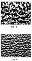
- Figure 3 is an optical enlargement at 25 times magnification showing the surface of a magnetic brush made with the prior art carrier particles shown in Figure 1.
- Figure 4 is an optical enlargement at 25 times magnification showing the surface of a magnetic brush made with the carrier particles shown in Figure 2.
- FIG. 3 A comparison of Figures 3 and 4 shows that the hairs of the brush of Figure 4 are closer together and that the voids between hairs are smaller. Since the hair pattern is to some extent transferred to a toner image developed by the brush, the hair pattern of Figure 4 will be less visible in the toner image than the pattern of Figure 3, and the quality of the toner image will be higher.
- the ferrite composite of this invention comprises a homogeneous mixture of two separate phases.
- the first phase is a spinel or "S" phase which has a cubic crystal structure and can be represented by the general formula MFe2O4, wherein M is at least one element that forms a spinel ferrite.
- M is at least one element that forms a spinel ferrite.
- such elements include the divalent elements nickel, cobalt, copper, zinc, manganese, magnesium, iron, and mixtures thereof. (When iron is used, the ferrite has the formula Fe3O4.)
- the preferred M element is zinc because it reduces the magnetic moment the most. Least preferred are iron, cobalt, and nickel because they reduce the magnetic moment the least; however, they still beneficially improve the surface morphology as shown in Figure 2.
- a mixture of monovalent and polyvalent elements can also be used as the M element, provided that the molar quantities of the elements are inversely proportional to their valences, that a spinel ferrite is formed, and that no cross-reaction occurs between the spinel phase and the "M" phase.
- M element A mixture of monovalent and polyvalent elements
- molar quantities of the elements are inversely proportional to their valences, that a spinel ferrite is formed, and that no cross-reaction occurs between the spinel phase and the "M" phase.
- chromium chromium
- sodium sodium
- other polyvalent elements such as aluminum can also be utilized to partially replace iron.
- the second phase is a magnetoplumbite phase or "M" phase which has a hexagonal crystal structure.
- the "M” phase has the general formula R x P (1-x) Fe12O19.
- R is a rare earth element selected from lanthanum, praseodymium, neodymium, samarium, europium, and mixtures of two or more thereof; lanthanum is preferred.
- P is strontium, barium, calcium, lead, or a mixture of two or more thereof. Of these four elements, calcium is the least preferred and strontium is the most preferred because it is less toxic and more commercially accepted.
- x is 0.1 to 0.4.
- the composites of this invention can be prepared by conventional procedures that are well known in the art of making ferrites. Suitable procedures are described, for example, in U.S. Patents 3,716,630, 4,623,603, and 4,042,518; "Spray Drying” by K. Masters, published by Leonard Hill Books London, pages 502-509; and "Ferromagnetic Materials,” Volume 3 edited E.P. Wohlfarth, and published by North Holland Publishing Company, Amsterdam, New York, page 315 et seq. Briefly, a typical preparation procedure can consist of mixing oxides of the elements in the appropriate proportion with an organic binder and water and spray-drying the mixture to form a fine dry particulate. The particulate can then be fired, which produces the ferrite composite.
- the composite is magnetized and can be optionally coated with a polymer, as is well known in the art, to better enable the carrier particles to triboelectrically charge toner particles. Since the presence of rare earth in the ferrite is intended to improve the conductivity of carrier particles, when a layer of resin is included on the carrier particles, it should be thin enough that the mass of particles remains conductive. Preferably the resin layer is discontinuous so that spots of bare ferrite on each particle provide conductive contact.
- the carrier particles can be passed through a sieve to obtain the desired range of sizes. A typical particle diameter range, including the optional polymer coating, is 5 to 60 micrometers, but smaller sized carrier particles, 5 to 20 micrometers, are preferred as they produce a better quality image. Additional details describing the preparation and use of ferrite magnetic carrier particles can be found in U.S. Patent 4,764,445.
- the composite ferrite carrier particles of this invention exhibit a coercivity of at least 23874 Ampere turns per meter (A/m) when magnetically saturated, and an induced magnetic moment of at least 1.88 x 10 ⁇ 8 Weber meters per gram (Wbm/g) of carrier in an applied field of 79580 A/m.
- Preferred particles were unexpectedly discovered to have a magnetic moment of 3.76 x 10 ⁇ 8 to 6.89 x 10 ⁇ 8 Wbm/g, which is less than that exhibited by similar particles which did not contain the spinel phase.
- Preferred particles also were found to have a high coercivity, typically 79580 to 238740 A/m.
- a high coercivity is desirable as it results in better carrier flow, which means that the carrier particles move by 180° flips or tumbles along the brush core rather than by sliding along the core of the brush, which results in a higher charge on the toner and more delivery of the toner to the photoconductor.
- the present invention encompasses two types of carrier particles.
- the first of these carriers comprises the ferrite composite, free of a binder, and exhibiting the requisite coercivity and induced magnetic moment. This type is preferred.
- the toner component of the invention can be a powdered resin which is optionally colored. It normally is prepared by compounding a resin with a colorant, i.e., a dye or pigment, and any other desired addenda.
- a colorant i.e., a dye or pigment
- the amount of colorant can vary over a wide range, e.g., from 3 to 20 weight percent of the toner. Combinations of colorants can be used.
- the toner can also contain minor components such as charge control agents and antiblocking agents.
- the mixture is heated and milled to disperse the colorant and other addenda in the resin.
- the mass is cooled, crushed into lumps, and finely ground.
- the resulting toner particles range in diameter from 0.5 to 25 micrometers with an average size of 1 to 16 micrometers.
- the average particle size ratio of carrier to toner lies within the range of 15:1 to 1:1.
- carrier-to-toner average particle size ratios of as high as 50:1 are also useful.
- Powders of strontium carbonate, lanthanum oxide, iron oxide, and either zinc, cupric, nickel, or magnesium oxide were weighed and mixed thoroughly.
- a stock solution was prepared by dissolving 4 weight percent (based on stock solution weight) of a binder resin and 0.4 weight percent ammonium polymethacrylate surfactant (sold by W. R. Grace and Co. under the trademark "Daxad-32") in distilled water.
- the powders were mixed with the stock solution in a 50:50 weight ratio, and the mixture was ball milled for about 24 hours then spray dried. The green bead particles thus formed were classified to obtain a suitable particle size distribution.
- the green bead was then fired at a temperature between 900 and 1250°C for 10 to 15 hours.
- the fired cake, thus obtained, was deagglomerated and the powder was sieved to be used as carrier.
- the resulting carriers had a two-phase composite structure with a spinel phase consisting of ZnFe2O4, CuFe2O4, NiFe2O4 or MgFe2O4 and an "M" phase consisting of Sr 0.79 La 0.21 Fe12O19.
- the mole ratio of the "M" phase was kept constant at 2.5 moles per 0.0, 0.5 or 1.0 mole of "S" phase.
- the sample with 0.0 mole of "S” phase forms a control having only a single phase structure.
- Table I shows that the magnetization (i.e., the magnetic moment) was reduced significantly as the concentration of spinel phase increased, and that the zinc spinel phase had the largest reduction in magnetization.
- Example 2 The "bare core” samples prepared in Example 1 were tested for charging properties as carriers by mixing them with a poly(styrene-co-butyl acrylate) toner having a volume average particle diameter of 2.9 micrometers and a ratio of volume average to number average particle size of 3.2/3.9. Table II gives the results.
- the charge on the toner, Q/M, in microcoulombs/gram was measured using a standard procedure in which the toner and carrier are placed on a horizontal electrode beneath a second horizontal electrode and are subjected to both an AC magnetic field (to cause agitation) and a DC electric field. When the toner jumps to the other electrode the change in the electric charge is measured and is divided by the weight of toner that jumped.
- the table gives the charge on the toner 0.5 second and 30 seconds after initiation of the AC magnetic field.
- the throw off is a measurement of the strength of the electrostatic bond between the toner and the carrier. A magnetic brush loaded with toner is rotated and the amount of toner that is thrown off the carrier is measured.
- a device employing a developer station as described in U.S. Patent 4,473,029 and a Buchner funnel disposed over the magnetic brush such that the filter paper is in the same relative position as the photoreceptor was used to determine throw-off of toner during rotation of the brush.
- the brush is rotated for each carrier for two minutes while vacuum is drawn and toner is collected on the filter paper.
- Table II shows that the charging properties and throw off of the bare core samples were acceptable.
- Coated carriers were made by mixing 50 grams of sample with 0.5 grams of poly(vinylidene fluoride) resin, sieving, rolling 15 minutes on a roll mill, curing in an oven for 4 hours at 230°C, and sieving again.
- the carriers were mixed with toner and tested for charging properties, as hereinabove described. Table III gives the results.
- Table III shows that the charging properties and throw off of the carriers were acceptable.
- Example 1 Samples prepared as in Example 1 which had 0.5, 0.75, and 1.0 mole of a ZnFe2O4 spinel phase per 2.5 moles of the "M" phase were heated with 1% resin, as in Example 2, and were tested in a xerographic copy machine at a toner concentration of 6 weight percent using the toner described in Example 2.
- the grain of the copies was analyzed and the analysis showed that the eye-weighted apparent graineness was reduced compared to the graineness of a copy made using a similar ferrite carrier which did not contain the spinel phase, in the same ratio with the same toner at the same charge level.
- the graineness of the sample containing 1.0 mole of the spinel phase was reduced the most, 20%, which corresponds to approximately 3 grain units. (One grain unit is a visually detectable difference.)
- Table IV shows that the tap density (measured after tapping the powder in a cylinder) increases with the concentration of the spinel phase, which is attributed to the morphology of the particles.
- concentration of the spinel phase can be used to control the surface morphology.
- a higher tap density is desirable if the magnetic brush is small and one desires more carrier on the brush.
- Examples 1 to 4 can be repeated using neodymium, praseodymium, samarium, europium, or a mixture thereof, or a mixture thereof with lanthanum, instead of lanthanum, with comparable results.
- the composites of this invention are useful as carriers in two-component developers for use in any electrostatographic process, including electrophotographic processes where the electrostatic charge on the photoconductor is induced by light, and dielectric recording processes, where the electrostatic charge on the photoconductor is induced electronically.
- the particles also can be used as part of a single component developer where they reduce dusting and provide a magnetically readable image. They can also be used as cleaning particles in a magnetic brush cleaning station. They are also useful in making soft and hard sintered magnets because the saturation magnetic moment and the coercivity can be independently controlled, and a smooth particle surface is produced.
Description
- The invention relates to hard ferrite magnetic carriers as claimed in claim 3 for use in electrostatographic development processes. More particularly, it relates to an interdispersed two-phase ferrite composite as defined in claim 1, wherein a first ferrite phase has a spinel structure, and a second ferrite phase has a magnetoplumbite structure, for use in such carriers.
- In an electrostatographic process an electrostatic latent image is formed on a photoconductor or other insulative material. That image can be developed by means of a rotating magnetic brush that consists of small magnetic carrier particles which, under the influence of magnets in the core of the brush, form fur-like hairs extending from the core. The magnetic brush triboelectrically charges toner particles and carries those charged toner particles to the electrostatic latent image on the photoconductor, thereby developing the image into a toner image. The toner image is then sometimes transferred to a receiver such as paper.
- In US-A-4,623,603, which corresponds to to EP-A-0 091 654, there is described an electrophotographic ferrite carrier having a double phase structure of the magnetoplumbite type hexagonal ferrite and a spinel type ferrite.
- A composite magnetic powder comprising two crystal phases of a magnetoplumbite structure hexagonal ferrite portion and a spinel structure ferrite portion is also known from EP-A-0 265 133.
- In U.S. Patent 4,764,445 there are described hard ferrite magnetic carrier particles, for use in two-component developers, which contain from about 1 to about 5% by weight of lanthanum. The presence of lanthanum in the ferrite increases the conductivity of the ferrite and improves its development efficiency.
- Lanthanum containing carrier particles consisting of an essentially homogenous ferromagnetic oxide for developing an electrostatic latent image are also known from US-A-4,172,722.
- Japanese Patent Laid-Open No. 124564/1987 (Application No. 263684/1985) titled "Carrier for Developing Electrostatic Charge Images," describes two-phase ferrite carrier particles, wherein one phase forms the core of the particle and a second phase forms the shell of the particle. The core has a hexagonal structure and a mixture of hexagonal and spinel structures and consists of 5 to 30% BaO, 5 to 30% ZnO, and 5 to 90% Fe₂O₃. The shell has a spinel structure and is formed from a ferrite slurry consisting (in mole percentage) of 5 to 20% NiO, 5 to 35% ZnO, and 40 to 70% Fe₂O₃, or a ferrite slurry in which a part of the aforementioned components is substituted by one or two or more sorts of metal of univalency or greater.
- It has now been discovered that the properties of the hard ferrite magnetic carrier particles described in aforementioned U.S. Patent 4,764,445 can be improved by the addition of zinc or similar element which causes formation of a two-phase composite structure. It has been found that the magnetic moment of the resulting composite structure is lower, which results in a softer magnetic brush having more hairs per unit area. This, in turn, results in lower granularity in a toner image made using that brush and therefore in better image quality. It has been further found that, unlike the carrier particles described in the aforementioned Japanese Patent Laid-Open No. 124564/1987, the two-phase composite carrier particles of this invention have a much higher coercivity, which results in better flow of the carrier particles, better charging of the toner, and the delivery of more toner to the photoconductor, i.e., increased development efficiency.
- The two-phase composite of the invention comprises a spinel phase represented by the general formula MFe₂O₄, wherein M is at least one element selected from Ni, Co, Cu, Zn, Mn, Mg, Fe and mixtures thereof, and a magnetoplumbite phase characterized in that said magnetoplumbite phase is represented by the general formula RxP1-xFe₁₂O₁₉, wherein R is lanthanum, neodymium, praseodymium, samarium, europium, or a mixture of two or more thereof, P is strontium, barium, calcium, lead, or a mixture of two or more thereof, and x is 0.1 to 0.4; the molar ratio spinel phase: magnetoplumbite phase in the composite being from 1:25 to 10:25.
- Some characteristics of ferrite composites and carriers of the invention in comparison to the prior art will be described with reference to the Figures in which:
- Figure 1 is a scanning electron micrograph made at 25 kilovolts and 5,000 times magnification showing a prior art hard magnetic ferrite particle having the composition Sr0.79La0.21Fe₁₂O₁₉, prepared according to Example 1 of hereinbefore cited U.S. Patent 4,764,445.
- Figure 2 is a scanning electron micrograph made at 25 kilovolts and 5,000 times magnification showing a homogeneous two-phase composite structure hard magnetic ferrite particle according to this invention having the composition:
0.1 mole spinel or "S" phase: ZnFeO₄
2.5 mole magnetoplumbite or "M" phase:
LaxSr(1-x)Fe₁₂O₁₉ wherein x is 0.21,
prepared according to Example 1. (Particles prepared according to Examples 2, 3, and 4 have the same surface morphology.) - Figure 3 is an optical enlargement at 25 times magnification showing the surface of a magnetic brush made with the prior art carrier particles shown in Figure 1.
- Figure 4 is an optical enlargement at 25 times magnification showing the surface of a magnetic brush made with the carrier particles shown in Figure 2.
- A comparison of Figures 3 and 4 shows that the hairs of the brush of Figure 4 are closer together and that the voids between hairs are smaller. Since the hair pattern is to some extent transferred to a toner image developed by the brush, the hair pattern of Figure 4 will be less visible in the toner image than the pattern of Figure 3, and the quality of the toner image will be higher.
- The ferrite composite of this invention comprises a homogeneous mixture of two separate phases. The first phase is a spinel or "S" phase which has a cubic crystal structure and can be represented by the general formula MFe₂O₄, wherein M is at least one element that forms a spinel ferrite. Examples of such elements include the divalent elements nickel, cobalt, copper, zinc, manganese, magnesium, iron, and mixtures thereof. (When iron is used, the ferrite has the formula Fe₃O₄.) The preferred M element is zinc because it reduces the magnetic moment the most. Least preferred are iron, cobalt, and nickel because they reduce the magnetic moment the least; however, they still beneficially improve the surface morphology as shown in Figure 2. A mixture of monovalent and polyvalent elements can also be used as the M element, provided that the molar quantities of the elements are inversely proportional to their valences, that a spinel ferrite is formed, and that no cross-reaction occurs between the spinel phase and the "M" phase. For example, one could use a mixture of 0.6 moles of chromium and 0.2 moles of sodium. In a similar way other polyvalent elements such as aluminum can also be utilized to partially replace iron.
- The second phase is a magnetoplumbite phase or "M" phase which has a hexagonal crystal structure. The "M" phase has the general formula RxP(1-x)Fe₁₂O₁₉. In that formula, R is a rare earth element selected from lanthanum, praseodymium, neodymium, samarium, europium, and mixtures of two or more thereof; lanthanum is preferred. Also in the general formula, P is strontium, barium, calcium, lead, or a mixture of two or more thereof. Of these four elements, calcium is the least preferred and strontium is the most preferred because it is less toxic and more commercially accepted. Also in the formula, x is 0.1 to 0.4. In the composite, 0.1 mole to 1 mole of the spinel phase is present for every 2.5 moles of the "M" phase. If more spinel phase is present developer pickup may occur, which means that the carrier may be transferred to the photoconductor, and if too little of the spinel phase is present the benefits of the invention, a smoother brush and higher image quality, will not be obtained.
- The composites of this invention can be prepared by conventional procedures that are well known in the art of making ferrites. Suitable procedures are described, for example, in U.S. Patents 3,716,630, 4,623,603, and 4,042,518; "Spray Drying" by K. Masters, published by Leonard Hill Books London, pages 502-509; and "Ferromagnetic Materials," Volume 3 edited E.P. Wohlfarth, and published by North Holland Publishing Company, Amsterdam, New York, page 315 et seq. Briefly, a typical preparation procedure can consist of mixing oxides of the elements in the appropriate proportion with an organic binder and water and spray-drying the mixture to form a fine dry particulate. The particulate can then be fired, which produces the ferrite composite. The composite is magnetized and can be optionally coated with a polymer, as is well known in the art, to better enable the carrier particles to triboelectrically charge toner particles. Since the presence of rare earth in the ferrite is intended to improve the conductivity of carrier particles, when a layer of resin is included on the carrier particles, it should be thin enough that the mass of particles remains conductive. Preferably the resin layer is discontinuous so that spots of bare ferrite on each particle provide conductive contact. The carrier particles can be passed through a sieve to obtain the desired range of sizes. A typical particle diameter range, including the optional polymer coating, is 5 to 60 micrometers, but smaller sized carrier particles, 5 to 20 micrometers, are preferred as they produce a better quality image. Additional details describing the preparation and use of ferrite magnetic carrier particles can be found in U.S. Patent 4,764,445.
- The composite ferrite carrier particles of this invention exhibit a coercivity of at least 23874 Ampere turns per meter (A/m) when magnetically saturated, and an induced magnetic moment of at least 1.88 x 10⁻⁸ Weber meters per gram (Wbm/g) of carrier in an applied field of 79580 A/m. Preferred particles were unexpectedly discovered to have a magnetic moment of 3.76 x 10⁻⁸ to 6.89 x 10⁻⁸ Wbm/g, which is less than that exhibited by similar particles which did not contain the spinel phase. Preferred particles also were found to have a high coercivity, typically 79580 to 238740 A/m. A high coercivity is desirable as it results in better carrier flow, which means that the carrier particles move by 180° flips or tumbles along the brush core rather than by sliding along the core of the brush, which results in a higher charge on the toner and more delivery of the toner to the photoconductor.
- The two phases in the composite are interdispersed or homogeneously mixed and it has not been possible to determine whether one phase or the other forms a continuous phase. Figure 2 shows that each carrier particle is formed of a number of small agglomerated crystallites. Comparing Figures 1 and 2, it is clear that the presence of the spinel phase results in smaller sized crystallites and fewer large voids, which present more surface contact with the toner particles. The particles are also generally spherical, as shown in Figure 2, which is desirable, as it increases the mechanical stability of the particles in the magnetic brush.
- The present invention encompasses two types of carrier particles. The first of these carriers comprises the ferrite composite, free of a binder, and exhibiting the requisite coercivity and induced magnetic moment. This type is preferred.
- The second is heterogeneous and comprises a composite of a binder and the inventive ferrite composite, exhibiting the requisite coercivity and induced magnetic moment. The ferrite composite is dispersed as discrete smaller particles throughout the binder; however, the resistivity of these binder-type particles must be comparable to the binderless carrier particles in order for the above-stated advantages to be observed. It may therefore be desirable to add conductive carbon black to the binder to insure electrical contact between the ferrite particles.
- An electrographic developer can be formed by mixing the carrier particles with toner particles in a suitable concentration. In developers of the invention, a wide range of concentrations of toner can be employed. The present developer preferably contains 70 to 99 weight percent carrier and 1 to 30 weight percent toner based on the total weight of the developer; most preferably, such concentration is 75 to 99 weight percent carrier and 1 to 25 weight percent toner.
- The toner component of the invention can be a powdered resin which is optionally colored. It normally is prepared by compounding a resin with a colorant, i.e., a dye or pigment, and any other desired addenda. The amount of colorant can vary over a wide range, e.g., from 3 to 20 weight percent of the toner. Combinations of colorants can be used. The toner can also contain minor components such as charge control agents and antiblocking agents.
- The mixture is heated and milled to disperse the colorant and other addenda in the resin. The mass is cooled, crushed into lumps, and finely ground. The resulting toner particles range in diameter from 0.5 to 25 micrometers with an average size of 1 to 16 micrometers. Preferably, the average particle size ratio of carrier to toner lies within the range of 15:1 to 1:1. However, carrier-to-toner average particle size ratios of as high as 50:1 are also useful.
- The invention is further illustrated by the following examples.
- Powders of strontium carbonate, lanthanum oxide, iron oxide, and either zinc, cupric, nickel, or magnesium oxide were weighed and mixed thoroughly. In a separate container, a stock solution was prepared by dissolving 4 weight percent (based on stock solution weight) of a binder resin and 0.4 weight percent ammonium polymethacrylate surfactant (sold by W. R. Grace and Co. under the trademark "Daxad-32") in distilled water. The powders were mixed with the stock solution in a 50:50 weight ratio, and the mixture was ball milled for about 24 hours then spray dried. The green bead particles thus formed were classified to obtain a suitable particle size distribution. The green bead was then fired at a temperature between 900 and 1250°C for 10 to 15 hours. The fired cake, thus obtained, was deagglomerated and the powder was sieved to be used as carrier. The resulting carriers had a two-phase composite structure with a spinel phase consisting of ZnFe₂O₄, CuFe₂O₄, NiFe₂O₄ or MgFe₂O₄ and an "M" phase consisting of Sr0.79La0.21Fe₁₂O₁₉. The mole ratio of the "M" phase was kept constant at 2.5 moles per 0.0, 0.5 or 1.0 mole of "S" phase. The sample with 0.0 mole of "S" phase forms a control having only a single phase structure.
- The samples were subjected to a vibrating sample magnetometer test. Table I gives the results:

- Table I shows that the magnetization (i.e., the magnetic moment) was reduced significantly as the concentration of spinel phase increased, and that the zinc spinel phase had the largest reduction in magnetization.
- X-ray diffraction studies were also performed on these samples. The x-ray diffraction patterns showed that both a spinel and an "M" phase were present and that no cross reaction had occurred between the two phases and among the various chemical species.
- The "bare core" samples prepared in Example 1 were tested for charging properties as carriers by mixing them with a poly(styrene-co-butyl acrylate) toner having a volume average particle diameter of 2.9 micrometers and a ratio of volume average to number average particle size of 3.2/3.9. Table II gives the results.

- In Table II, the charge on the toner, Q/M, in microcoulombs/gram, was measured using a standard procedure in which the toner and carrier are placed on a horizontal electrode beneath a second horizontal electrode and are subjected to both an AC magnetic field (to cause agitation) and a DC electric field. When the toner jumps to the other electrode the change in the electric charge is measured and is divided by the weight of toner that jumped. The table gives the charge on the toner 0.5 second and 30 seconds after initiation of the AC magnetic field. Also in the above table, the throw off is a measurement of the strength of the electrostatic bond between the toner and the carrier. A magnetic brush loaded with toner is rotated and the amount of toner that is thrown off the carrier is measured. A device employing a developer station as described in U.S. Patent 4,473,029 and a Buchner funnel disposed over the magnetic brush such that the filter paper is in the same relative position as the photoreceptor was used to determine throw-off of toner during rotation of the brush. The brush is rotated for each carrier for two minutes while vacuum is drawn and toner is collected on the filter paper. Table II shows that the charging properties and throw off of the bare core samples were acceptable.
- Coated carriers were made by mixing 50 grams of sample with 0.5 grams of poly(vinylidene fluoride) resin, sieving, rolling 15 minutes on a roll mill, curing in an oven for 4 hours at 230°C, and sieving again. The carriers were mixed with toner and tested for charging properties, as hereinabove described. Table III gives the results.

- Table III shows that the charging properties and throw off of the carriers were acceptable.
- Samples prepared as in Example 1 which had 0.5, 0.75, and 1.0 mole of a ZnFe₂O₄ spinel phase per 2.5 moles of the "M" phase were heated with 1% resin, as in Example 2, and were tested in a xerographic copy machine at a toner concentration of 6 weight percent using the toner described in Example 2. The grain of the copies was analyzed and the analysis showed that the eye-weighted apparent graineness was reduced compared to the graineness of a copy made using a similar ferrite carrier which did not contain the spinel phase, in the same ratio with the same toner at the same charge level. The graineness of the sample containing 1.0 mole of the spinel phase was reduced the most, 20%, which corresponds to approximately 3 grain units. (One grain unit is a visually detectable difference.)
- Using ASTM test B527-85, the tap densities of samples prepared as in Example 1 were measured. Table IV gives the results.

- Table IV shows that the tap density (measured after tapping the powder in a cylinder) increases with the concentration of the spinel phase, which is attributed to the morphology of the particles. Thus, the concentration of the spinel phase can be used to control the surface morphology. A higher tap density is desirable if the magnetic brush is small and one desires more carrier on the brush.
- Examples 1 to 4 can be repeated using neodymium, praseodymium, samarium, europium, or a mixture thereof, or a mixture thereof with lanthanum, instead of lanthanum, with comparable results.
- The composites of this invention are useful as carriers in two-component developers for use in any electrostatographic process, including electrophotographic processes where the electrostatic charge on the photoconductor is induced by light, and dielectric recording processes, where the electrostatic charge on the photoconductor is induced electronically. The particles also can be used as part of a single component developer where they reduce dusting and provide a magnetically readable image. They can also be used as cleaning particles in a magnetic brush cleaning station. They are also useful in making soft and hard sintered magnets because the saturation magnetic moment and the coercivity can be independently controlled, and a smooth particle surface is produced.
Claims (4)
- An interdispersed two-phase ferrite composite which comprises a spinel phase represented by the general formula MFe₂O₄, wherein M is at least one element selected from Ni, Co, Cu, Zn, Mn, Mg, Fe and mixtures thereof, and a magnetoplumbite phase, characterized in that said magnetoplumbite phase is represented by the general formula RxP1-xFe₁₂O₁₉, wherein R is lanthanum, neodymium, praseodymium, samarium, europium, or a mixture of two or more thereof, P is strontium, barium, calcium, lead, or a mixture of two or more thereof, and x is 0.1 to 0.4, the molar ratio spinel phase: magnetoplumbite phase in the composite being from 1:25 to 10:25.
- A composite according to claim 1 characterized in that said spinel phase has the formula ZnFe₂O₄ and said magnetoplumbite phase has the general formula LaxSr(1-x)Fe₁₂O₁₉.
- Hard ferrite magnetic carrier particles for use in electrostatography comprising the ferrite composite according to claim 1, magnetized and coated with a polymer.
- An electrographic developer comprising a mixture of 75 to 99 weight percent carrier particles according to claim 3 and 1 to 25 weight percent toner particles.
Applications Claiming Priority (2)
| Application Number | Priority Date | Filing Date | Title |
|---|---|---|---|
| US229366 | 1988-08-05 | ||
| US07/229,366 US4855205A (en) | 1988-08-05 | 1988-08-05 | Interdispersed two-phase ferrite composite and carrier therefrom |
Publications (3)
| Publication Number | Publication Date |
|---|---|
| EP0353627A2 EP0353627A2 (en) | 1990-02-07 |
| EP0353627A3 EP0353627A3 (en) | 1991-10-02 |
| EP0353627B1 true EP0353627B1 (en) | 1995-09-27 |
Family
ID=22860906
Family Applications (1)
| Application Number | Title | Priority Date | Filing Date |
|---|---|---|---|
| EP89113843A Expired - Lifetime EP0353627B1 (en) | 1988-08-05 | 1989-07-27 | Interdispersed two-phase ferrite composite |
Country Status (4)
| Country | Link |
|---|---|
| US (1) | US4855205A (en) |
| EP (1) | EP0353627B1 (en) |
| JP (1) | JP2749651B2 (en) |
| DE (1) | DE68924383T2 (en) |
Families Citing this family (35)
| Publication number | Priority date | Publication date | Assignee | Title |
|---|---|---|---|---|
| US4855206A (en) * | 1988-08-05 | 1989-08-08 | Eastman Kodak Company | Rare earth containing magnetic carrier particles |
| US5061586A (en) * | 1990-04-05 | 1991-10-29 | Eastman Kodak Company | Glass composite magnetic carrier particles |
| US5106714A (en) * | 1990-08-01 | 1992-04-21 | Eastman Kodak Company | Interdispersed two-phase ferrite composite and electrographic magnetic carrier particles therefrom |
| US5104761A (en) * | 1990-09-14 | 1992-04-14 | Eastman Kodak Company | Interdispersed three-phase ferrite composite and electrographic magnetic carrier particles therefrom |
| US5378384A (en) * | 1991-09-19 | 1995-01-03 | Minnesota Mining And Manufacturing Company | Process of making hexagonal magnetic ferrite pigment for high density magnetic recording applications |
| US5190841A (en) * | 1991-12-19 | 1993-03-02 | Eastman Kodak Company | Two-phase ferroelectric-ferromagnetic composite and carrier therefrom |
| EP0580135B1 (en) * | 1992-07-22 | 1997-04-16 | Canon Kabushiki Kaisha | Carrier for use in electrophotography, two component-type developer and image forming method |
| US5306592A (en) * | 1992-10-29 | 1994-04-26 | Eastman Kodak Company | Method of preparing electrographic magnetic carrier particles |
| US5268249A (en) * | 1992-10-29 | 1993-12-07 | Eastman Kodak Company | Magnetic carrier particles |
| US5798198A (en) * | 1993-04-09 | 1998-08-25 | Powdertech Corporation | Non-stoichiometric lithium ferrite carrier |
| US5616414A (en) * | 1993-12-28 | 1997-04-01 | Imation Corp. | Hexagonal magnetic ferrite pigment for high density magnetic recording applications |
| US5422216A (en) * | 1994-03-01 | 1995-06-06 | Steward | Developer composition and method of preparing the same |
| US5512404A (en) * | 1994-08-29 | 1996-04-30 | Eastman Kodak Company | Developer compositions exhibiting high development speeds |
| US5500320A (en) * | 1994-08-29 | 1996-03-19 | Eastman Kodak Company | High speed developer compositions with ferrite carriers |
| US5580655A (en) * | 1995-03-03 | 1996-12-03 | Dow Corning Corporation | Silica nanoparticles |
| JP2897871B2 (en) * | 1995-08-11 | 1999-05-31 | ティーディーケイ株式会社 | Magnet powder, sintered magnet, bonded magnet and magnetic recording medium |
| JP3261946B2 (en) * | 1995-10-12 | 2002-03-04 | ミノルタ株式会社 | Carrier for developing electrostatic images |
| US6737011B1 (en) * | 1997-12-25 | 2004-05-18 | Hitachi Metals, Ltd. | Method for producing ferrite magnet |
| US5998076A (en) * | 1998-03-09 | 1999-12-07 | Xerox Corporation | Carrier |
| US6528225B1 (en) | 1998-03-09 | 2003-03-04 | Xerox Corporation | Carrier |
| WO2001088623A1 (en) * | 2000-05-17 | 2001-11-22 | Heidelberg Digital L.L.C. | Method for using hard magnetic carriers in an electrographic process |
| US6232026B1 (en) | 2000-05-17 | 2001-05-15 | Heidelberg Digital L.L.C. | Magnetic carrier particles |
| US6228549B1 (en) | 2000-05-17 | 2001-05-08 | Heidelberg Digital L.L.C. | Magnetic carrier particles |
| US6723481B2 (en) | 2000-05-17 | 2004-04-20 | Heidelberger Druckmaschinen Ag | Method for using hard magnetic carriers in an electrographic process |
| US6391509B1 (en) | 2000-08-17 | 2002-05-21 | Xerox Corporation | Coated carriers |
| JP2002313618A (en) * | 2001-02-07 | 2002-10-25 | Sumitomo Special Metals Co Ltd | Permanent magnet and its manufacturing method |
| US6511780B1 (en) | 2001-07-30 | 2003-01-28 | Xerox Corporation | Carrier particles |
| US7091412B2 (en) | 2002-03-04 | 2006-08-15 | Nanoset, Llc | Magnetically shielded assembly |
| US7162302B2 (en) | 2002-03-04 | 2007-01-09 | Nanoset Llc | Magnetically shielded assembly |
| JP3744859B2 (en) | 2002-02-01 | 2006-02-15 | 三洋電機株式会社 | Molded body and manufacturing method thereof |
| US7014971B2 (en) * | 2003-03-07 | 2006-03-21 | Xerox Corporation | Carrier compositions |
| US20060199094A1 (en) | 2005-03-07 | 2006-09-07 | Xerox Corporation | Carrier and developer compositions |
| JP4803730B2 (en) * | 2006-03-30 | 2011-10-26 | パウダーテック株式会社 | Ferromagnetic material powder, carrier for electrophotographic developer, production method thereof, and electrophotographic developer |
| JP5086681B2 (en) * | 2007-03-30 | 2012-11-28 | Dowaエレクトロニクス株式会社 | Carrier core material for electrophotographic developer and method for producing the same, carrier for electrophotographic developer, and electrophotographic developer |
| JP5692766B1 (en) * | 2014-01-20 | 2015-04-01 | パウダーテック株式会社 | Ferrite carrier core material and ferrite carrier for electrophotographic developer using ferrite particles having outer shell structure, and electrophotographic developer using the ferrite carrier |
Family Cites Families (15)
| Publication number | Priority date | Publication date | Assignee | Title |
|---|---|---|---|---|
| US2900344A (en) * | 1953-07-29 | 1959-08-18 | Philips Corp | Making anisotropic permanent magnets |
| JPS51124434A (en) * | 1975-04-22 | 1976-10-29 | Ricoh Co Ltd | Duplicating method for plural sheets |
| US3996392A (en) * | 1975-10-29 | 1976-12-07 | Xerox Corporation | Humidity-insensitive ferrite developer materials |
| JPS55130862A (en) * | 1979-03-27 | 1980-10-11 | Toranosuke Kawaguchi | Oxide permanent magnet |
| JPS6054907B2 (en) * | 1980-01-14 | 1985-12-02 | 富士電気化学株式会社 | Wide temperature range ferrite storage core |
| JPS58202456A (en) * | 1982-04-07 | 1983-11-25 | Hitachi Metals Ltd | Electrophotographic ferrite carrier |
| JPS58215663A (en) * | 1982-06-08 | 1983-12-15 | Hitachi Metals Ltd | Ferrite carrier for electrophotography |
| JPS5994763A (en) * | 1982-11-22 | 1984-05-31 | Mita Ind Co Ltd | Two-component type developer for magnetic brush developing |
| JPS59127054A (en) * | 1983-01-11 | 1984-07-21 | Hitachi Metals Ltd | Electrophotographic developing agent |
| US4540645A (en) * | 1983-01-31 | 1985-09-10 | Mita Industrial Co Ltd | Magnetic brush development method |
| JPS59197047A (en) * | 1983-04-25 | 1984-11-08 | Tomoegawa Paper Co Ltd | Magnetic color toner |
| JPS607441A (en) * | 1983-06-28 | 1985-01-16 | Canon Inc | Magnetic color toner |
| JPS61296363A (en) * | 1985-06-26 | 1986-12-27 | Mitsubishi Chem Ind Ltd | Coated carrier for electrophotography |
| JPS62124564A (en) * | 1985-11-26 | 1987-06-05 | Hitachi Metals Ltd | Carrier for developing electrostatic charge image |
| EP0265133A3 (en) * | 1986-10-13 | 1990-01-10 | Matsushita Electric Industrial Co., Ltd. | Composite magnetic powder, method for producing the same and recording medium containing the same |
-
1988
- 1988-08-05 US US07/229,366 patent/US4855205A/en not_active Expired - Lifetime
-
1989
- 1989-07-27 DE DE68924383T patent/DE68924383T2/en not_active Expired - Fee Related
- 1989-07-27 EP EP89113843A patent/EP0353627B1/en not_active Expired - Lifetime
- 1989-08-04 JP JP1201472A patent/JP2749651B2/en not_active Expired - Lifetime
Also Published As
| Publication number | Publication date |
|---|---|
| EP0353627A3 (en) | 1991-10-02 |
| EP0353627A2 (en) | 1990-02-07 |
| JPH0288429A (en) | 1990-03-28 |
| DE68924383T2 (en) | 1996-05-15 |
| JP2749651B2 (en) | 1998-05-13 |
| US4855205A (en) | 1989-08-08 |
| DE68924383D1 (en) | 1995-11-02 |
Similar Documents
| Publication | Publication Date | Title |
|---|---|---|
| EP0353627B1 (en) | Interdispersed two-phase ferrite composite | |
| EP0353630B1 (en) | Rare earth-containing magnetic carrier particles | |
| US5106714A (en) | Interdispersed two-phase ferrite composite and electrographic magnetic carrier particles therefrom | |
| EP0086444B1 (en) | Magnetic carrier powder for two-component toner | |
| EP0296072B1 (en) | Electrostatic magnetic carrier particles | |
| US5104761A (en) | Interdispersed three-phase ferrite composite and electrographic magnetic carrier particles therefrom | |
| JP4668574B2 (en) | Mg-based ferrite, electrophotographic developer carrier and developer using the ferrite | |
| US4485162A (en) | Magnetic carrier powder having a wide chargeable range of electric resistance useful for magnetic brush development | |
| EP2107425B1 (en) | Carrier core material for an electrophotographic developer, carrier, and electrophotographic developer using the carrier | |
| US5061586A (en) | Glass composite magnetic carrier particles | |
| DE60126015T2 (en) | Electrographic methods using developer compositions of hard magnetic carrier particles | |
| EP1156376B1 (en) | Magnetic carrier particles | |
| EP0547620A1 (en) | Two-phase ferroelectric-ferromagnetic composite and carrier therefrom | |
| JP4540668B2 (en) | Mg-based ferrite material, carrier for electrophotographic development containing the ferrite material, and developer containing the carrier | |
| EP1947519A1 (en) | Ferrite carrier for electrophotographic developer and electrophotographic developer | |
| JPS62267766A (en) | Carrier for developing electrostatic charge image | |
| CN100557726C (en) | Mg-based ferrite, the developer that contains this ferritic electrophotographic development carrier and contain this carrier | |
| JPS62242961A (en) | Carrier for developing electrostatic charge image | |
| JPH0715598B2 (en) | Ferrite carrier for electrophotographic development | |
| EP0640881B1 (en) | Magnetic toner | |
| JP2503221B2 (en) | Developer for electrostatic image | |
| US20030073022A1 (en) | Electrophotographic carrier core magnetite powder | |
| JPS6327858A (en) | Carrier particle for developing electrostatic charge image | |
| JP2004361687A (en) | Carrier core material for electrophotographic development | |
| JPH0685094B2 (en) | Ferrite carrier |
Legal Events
| Date | Code | Title | Description |
|---|---|---|---|
| PUAI | Public reference made under article 153(3) epc to a published international application that has entered the european phase |
Free format text: ORIGINAL CODE: 0009012 |
|
| AK | Designated contracting states |
Kind code of ref document: A2 Designated state(s): DE FR GB NL |
|
| PUAL | Search report despatched |
Free format text: ORIGINAL CODE: 0009013 |
|
| AK | Designated contracting states |
Kind code of ref document: A3 Designated state(s): DE FR GB NL |
|
| 17P | Request for examination filed |
Effective date: 19910917 |
|
| 17Q | First examination report despatched |
Effective date: 19930927 |
|
| GRAA | (expected) grant |
Free format text: ORIGINAL CODE: 0009210 |
|
| AK | Designated contracting states |
Kind code of ref document: B1 Designated state(s): DE FR GB NL |
|
| REF | Corresponds to: |
Ref document number: 68924383 Country of ref document: DE Date of ref document: 19951102 |
|
| ET | Fr: translation filed | ||
| PLBE | No opposition filed within time limit |
Free format text: ORIGINAL CODE: 0009261 |
|
| STAA | Information on the status of an ep patent application or granted ep patent |
Free format text: STATUS: NO OPPOSITION FILED WITHIN TIME LIMIT |
|
| 26N | No opposition filed | ||
| REG | Reference to a national code |
Ref country code: GB Ref legal event code: 732E |
|
| NLS | Nl: assignments of ep-patents |
Owner name: NEXPRESS SOLUTIONS LLC |
|
| REG | Reference to a national code |
Ref country code: GB Ref legal event code: IF02 |
|
| REG | Reference to a national code |
Ref country code: GB Ref legal event code: 732E |
|
| PGFP | Annual fee paid to national office [announced via postgrant information from national office to epo] |
Ref country code: GB Payment date: 20050614 Year of fee payment: 17 |
|
| PGFP | Annual fee paid to national office [announced via postgrant information from national office to epo] |
Ref country code: NL Payment date: 20050616 Year of fee payment: 17 |
|
| PGFP | Annual fee paid to national office [announced via postgrant information from national office to epo] |
Ref country code: FR Payment date: 20050706 Year of fee payment: 17 |
|
| PGFP | Annual fee paid to national office [announced via postgrant information from national office to epo] |
Ref country code: DE Payment date: 20050729 Year of fee payment: 17 |
|
| NLS | Nl: assignments of ep-patents |
Owner name: NEXPRESS SOLUTIONS, INC. Effective date: 20050629 Owner name: EASTMAN KODAK COMPANY Effective date: 20050629 |
|
| PG25 | Lapsed in a contracting state [announced via postgrant information from national office to epo] |
Ref country code: GB Free format text: LAPSE BECAUSE OF NON-PAYMENT OF DUE FEES Effective date: 20060727 |
|
| PG25 | Lapsed in a contracting state [announced via postgrant information from national office to epo] |
Ref country code: NL Free format text: LAPSE BECAUSE OF NON-PAYMENT OF DUE FEES Effective date: 20070201 Ref country code: DE Free format text: LAPSE BECAUSE OF NON-PAYMENT OF DUE FEES Effective date: 20070201 |
|
| GBPC | Gb: european patent ceased through non-payment of renewal fee |
Effective date: 20060727 |
|
| NLV4 | Nl: lapsed or anulled due to non-payment of the annual fee |
Effective date: 20070201 |
|
| REG | Reference to a national code |
Ref country code: FR Ref legal event code: ST Effective date: 20070330 |
|
| PG25 | Lapsed in a contracting state [announced via postgrant information from national office to epo] |
Ref country code: FR Free format text: LAPSE BECAUSE OF NON-PAYMENT OF DUE FEES Effective date: 20060731 |