EP0353602A2 - A system for reducing noise holograms - Google Patents
A system for reducing noise holograms Download PDFInfo
- Publication number
- EP0353602A2 EP0353602A2 EP89113732A EP89113732A EP0353602A2 EP 0353602 A2 EP0353602 A2 EP 0353602A2 EP 89113732 A EP89113732 A EP 89113732A EP 89113732 A EP89113732 A EP 89113732A EP 0353602 A2 EP0353602 A2 EP 0353602A2
- Authority
- EP
- European Patent Office
- Prior art keywords
- recording
- substrate
- absorbent member
- thickness
- absorbent
- Prior art date
- Legal status (The legal status is an assumption and is not a legal conclusion. Google has not performed a legal analysis and makes no representation as to the accuracy of the status listed.)
- Granted
Links
- 230000002745 absorbent Effects 0.000 claims abstract description 64
- 239000002250 absorbent Substances 0.000 claims abstract description 64
- 239000000758 substrate Substances 0.000 claims abstract description 19
- 230000007423 decrease Effects 0.000 claims abstract description 6
- 239000000463 material Substances 0.000 claims description 21
- 108010010803 Gelatin Proteins 0.000 claims description 13
- 229920000159 gelatin Polymers 0.000 claims description 13
- 239000008273 gelatin Substances 0.000 claims description 13
- 235000019322 gelatine Nutrition 0.000 claims description 13
- 235000011852 gelatine desserts Nutrition 0.000 claims description 13
- 230000008859 change Effects 0.000 claims description 11
- 239000012530 fluid Substances 0.000 claims description 11
- 230000003247 decreasing effect Effects 0.000 claims description 4
- 239000011521 glass Substances 0.000 claims description 4
- 230000010363 phase shift Effects 0.000 abstract description 10
- XLYOFNOQVPJJNP-UHFFFAOYSA-N water Substances O XLYOFNOQVPJJNP-UHFFFAOYSA-N 0.000 description 16
- 238000000034 method Methods 0.000 description 6
- 239000003921 oil Substances 0.000 description 6
- 230000003287 optical effect Effects 0.000 description 6
- 230000003068 static effect Effects 0.000 description 6
- IJGRMHOSHXDMSA-UHFFFAOYSA-N Atomic nitrogen Chemical compound N#N IJGRMHOSHXDMSA-UHFFFAOYSA-N 0.000 description 4
- 238000010521 absorption reaction Methods 0.000 description 4
- 238000013459 approach Methods 0.000 description 4
- 238000007654 immersion Methods 0.000 description 4
- 239000007788 liquid Substances 0.000 description 4
- 230000005540 biological transmission Effects 0.000 description 3
- 230000001965 increasing effect Effects 0.000 description 3
- 230000033001 locomotion Effects 0.000 description 3
- 238000004519 manufacturing process Methods 0.000 description 3
- 239000002480 mineral oil Substances 0.000 description 3
- 235000010446 mineral oil Nutrition 0.000 description 3
- XKRFYHLGVUSROY-UHFFFAOYSA-N Argon Chemical compound [Ar] XKRFYHLGVUSROY-UHFFFAOYSA-N 0.000 description 2
- CTQNGGLPUBDAKN-UHFFFAOYSA-N O-Xylene Chemical group CC1=CC=CC=C1C CTQNGGLPUBDAKN-UHFFFAOYSA-N 0.000 description 2
- 230000008901 benefit Effects 0.000 description 2
- 230000001419 dependent effect Effects 0.000 description 2
- 229910001873 dinitrogen Inorganic materials 0.000 description 2
- 238000001704 evaporation Methods 0.000 description 2
- 230000007246 mechanism Effects 0.000 description 2
- 238000012986 modification Methods 0.000 description 2
- 230000004048 modification Effects 0.000 description 2
- 230000008569 process Effects 0.000 description 2
- 230000008961 swelling Effects 0.000 description 2
- OKTJSMMVPCPJKN-UHFFFAOYSA-N Carbon Chemical compound [C] OKTJSMMVPCPJKN-UHFFFAOYSA-N 0.000 description 1
- 229910052786 argon Inorganic materials 0.000 description 1
- 230000000712 assembly Effects 0.000 description 1
- 238000000429 assembly Methods 0.000 description 1
- 229910052799 carbon Inorganic materials 0.000 description 1
- 230000015556 catabolic process Effects 0.000 description 1
- 239000003795 chemical substances by application Substances 0.000 description 1
- 238000010276 construction Methods 0.000 description 1
- 230000008602 contraction Effects 0.000 description 1
- 238000006731 degradation reaction Methods 0.000 description 1
- 230000001934 delay Effects 0.000 description 1
- JXSJBGJIGXNWCI-UHFFFAOYSA-N diethyl 2-[(dimethoxyphosphorothioyl)thio]succinate Chemical compound CCOC(=O)CC(SP(=S)(OC)OC)C(=O)OCC JXSJBGJIGXNWCI-UHFFFAOYSA-N 0.000 description 1
- 230000000694 effects Effects 0.000 description 1
- 238000005516 engineering process Methods 0.000 description 1
- 230000008020 evaporation Effects 0.000 description 1
- 108010025899 gelatin film Proteins 0.000 description 1
- 239000012535 impurity Substances 0.000 description 1
- 230000001939 inductive effect Effects 0.000 description 1
- STZCRXQWRGQSJD-GEEYTBSJSA-M methyl orange Chemical compound [Na+].C1=CC(N(C)C)=CC=C1\N=N\C1=CC=C(S([O-])(=O)=O)C=C1 STZCRXQWRGQSJD-GEEYTBSJSA-M 0.000 description 1
- 229940012189 methyl orange Drugs 0.000 description 1
- 239000000203 mixture Substances 0.000 description 1
- 229910052757 nitrogen Inorganic materials 0.000 description 1
- 230000001681 protective effect Effects 0.000 description 1
- 230000005855 radiation Effects 0.000 description 1
- 230000009467 reduction Effects 0.000 description 1
- 230000001105 regulatory effect Effects 0.000 description 1
- 230000010076 replication Effects 0.000 description 1
- 229920006395 saturated elastomer Polymers 0.000 description 1
- 239000004065 semiconductor Substances 0.000 description 1
- 230000035945 sensitivity Effects 0.000 description 1
- 239000002904 solvent Substances 0.000 description 1
- 230000006641 stabilisation Effects 0.000 description 1
- 238000011105 stabilization Methods 0.000 description 1
- 230000000087 stabilizing effect Effects 0.000 description 1
- 239000000126 substance Substances 0.000 description 1
- 239000008096 xylene Substances 0.000 description 1
Images
Classifications
-
- G—PHYSICS
- G03—PHOTOGRAPHY; CINEMATOGRAPHY; ANALOGOUS TECHNIQUES USING WAVES OTHER THAN OPTICAL WAVES; ELECTROGRAPHY; HOLOGRAPHY
- G03H—HOLOGRAPHIC PROCESSES OR APPARATUS
- G03H1/00—Holographic processes or apparatus using light, infrared or ultraviolet waves for obtaining holograms or for obtaining an image from them; Details peculiar thereto
- G03H1/02—Details of features involved during the holographic process; Replication of holograms without interference recording
- G03H1/024—Hologram nature or properties
- G03H1/0248—Volume holograms
-
- G—PHYSICS
- G03—PHOTOGRAPHY; CINEMATOGRAPHY; ANALOGOUS TECHNIQUES USING WAVES OTHER THAN OPTICAL WAVES; ELECTROGRAPHY; HOLOGRAPHY
- G03H—HOLOGRAPHIC PROCESSES OR APPARATUS
- G03H1/00—Holographic processes or apparatus using light, infrared or ultraviolet waves for obtaining holograms or for obtaining an image from them; Details peculiar thereto
- G03H1/02—Details of features involved during the holographic process; Replication of holograms without interference recording
- G03H1/0252—Laminate comprising a hologram layer
- G03H1/0256—Laminate comprising a hologram layer having specific functional layer
-
- G—PHYSICS
- G03—PHOTOGRAPHY; CINEMATOGRAPHY; ANALOGOUS TECHNIQUES USING WAVES OTHER THAN OPTICAL WAVES; ELECTROGRAPHY; HOLOGRAPHY
- G03H—HOLOGRAPHIC PROCESSES OR APPARATUS
- G03H1/00—Holographic processes or apparatus using light, infrared or ultraviolet waves for obtaining holograms or for obtaining an image from them; Details peculiar thereto
- G03H1/04—Processes or apparatus for producing holograms
- G03H1/18—Particular processing of hologram record carriers, e.g. for obtaining blazed holograms
- G03H1/181—Pre-exposure processing, e.g. hypersensitisation
-
- G—PHYSICS
- G03—PHOTOGRAPHY; CINEMATOGRAPHY; ANALOGOUS TECHNIQUES USING WAVES OTHER THAN OPTICAL WAVES; ELECTROGRAPHY; HOLOGRAPHY
- G03H—HOLOGRAPHIC PROCESSES OR APPARATUS
- G03H1/00—Holographic processes or apparatus using light, infrared or ultraviolet waves for obtaining holograms or for obtaining an image from them; Details peculiar thereto
- G03H1/02—Details of features involved during the holographic process; Replication of holograms without interference recording
- G03H2001/0208—Individual components other than the hologram
- G03H2001/0232—Mechanical components or mechanical aspects not otherwise provided for
-
- G—PHYSICS
- G03—PHOTOGRAPHY; CINEMATOGRAPHY; ANALOGOUS TECHNIQUES USING WAVES OTHER THAN OPTICAL WAVES; ELECTROGRAPHY; HOLOGRAPHY
- G03H—HOLOGRAPHIC PROCESSES OR APPARATUS
- G03H1/00—Holographic processes or apparatus using light, infrared or ultraviolet waves for obtaining holograms or for obtaining an image from them; Details peculiar thereto
- G03H1/04—Processes or apparatus for producing holograms
- G03H1/18—Particular processing of hologram record carriers, e.g. for obtaining blazed holograms
- G03H2001/186—Swelling or shrinking the holographic record or compensation thereof, e.g. for controlling the reconstructed wavelength
-
- G—PHYSICS
- G03—PHOTOGRAPHY; CINEMATOGRAPHY; ANALOGOUS TECHNIQUES USING WAVES OTHER THAN OPTICAL WAVES; ELECTROGRAPHY; HOLOGRAPHY
- G03H—HOLOGRAPHIC PROCESSES OR APPARATUS
- G03H1/00—Holographic processes or apparatus using light, infrared or ultraviolet waves for obtaining holograms or for obtaining an image from them; Details peculiar thereto
- G03H1/22—Processes or apparatus for obtaining an optical image from holograms
- G03H1/2202—Reconstruction geometries or arrangements
- G03H2001/2223—Particular relationship between light source, hologram and observer
-
- G—PHYSICS
- G03—PHOTOGRAPHY; CINEMATOGRAPHY; ANALOGOUS TECHNIQUES USING WAVES OTHER THAN OPTICAL WAVES; ELECTROGRAPHY; HOLOGRAPHY
- G03H—HOLOGRAPHIC PROCESSES OR APPARATUS
- G03H2223/00—Optical components
- G03H2223/25—Index matching material
-
- G—PHYSICS
- G03—PHOTOGRAPHY; CINEMATOGRAPHY; ANALOGOUS TECHNIQUES USING WAVES OTHER THAN OPTICAL WAVES; ELECTROGRAPHY; HOLOGRAPHY
- G03H—HOLOGRAPHIC PROCESSES OR APPARATUS
- G03H2250/00—Laminate comprising a hologram layer
- G03H2250/42—Reflective layer
Definitions
- This invention generally relates to a system and method for reducing noise holograms and, more specifically, to an improved system and method for inducing phase shifts of reflective light during construction of the primary hologram.
- High quality holographic optical elements are used in defraction optics display systems, such as head up displays (HUDs), for advanced aircraft, helmet mounted displays, laser protective devices, narrow band reflective filters, and holographic high gain screens for simulators. These are only a few of the many uses of high quality reflective holograms.
- spurious noise holograms are generated by reflections from surfaces which are interfaces of materials of different indexes of refraction, such as air/glass interfaces of the transparent surfaces of a recording cover plate, a hologram substrate, the recording medium itself, and optical elements used to generate the recording beams. These reflections can combine with the primary holographic beams at the recording film to form spurious reflection holograms, when the beams are in the opposite direction, and spurious transmission holograms when the beams are in the same direction. A subsequent display system using this hologram will be degraded by ghost images from the spurious reflection hologram recordings, and rainbow-like flair patterns from the spurious transmission hologram recordings.
- U.S. Patent No. 3,601,017 Another attempt to suppress spurious holograms is disclosed in U.S. Patent No. 3,601,017.
- an immersion liquid is applied to either the surface of the recording medium or the surface of a transparent support member, which surface is remote from the direction of light incidence.
- the thickness of the immersion agent layer is varied over time during an exposure by evaporation or, when it is not so readily evaporated, by generating acoustic or surface waves which, during their reflection, directionally modulate the wave field in the liquid.
- the transparent immersion liquid is O-xylene.
- This system also has drawbacks, including the fact that the evaporating liquid is not a good optical surface. Further, the variation in thickness would not appear to be highly regulated, particularly when using generated waves.
- the present invention seeks to overcome the disadvantages found in the prior art by providing a recording assembly that includes a mirror positioned at the bottom of the recording assembly, and a reservoir of index matching fluid is adjacent to a reflective surface of the mirror.
- a recording medium is then placed on a side of the reservoir opposite the mirror.
- a substrate supports the recording medium, as well as an absorbent, transparent member on a side of the substrate opposite the recording medium.
- the absorbent member is out of moisture equilibrium with the surrounding environment. Thereby, the absorbent, transparent member can either absorb moisture from the environment or release it into the environment, depending upon the moisture differential between the transparent member and the environment.
- the recording assembly can be recording an interference pattern in the recording medium.
- the interference fringes or patterns which constitute the spurious holograms are blurred to an extent sufficient to practically remove the interference caused by the spurious hologram.
- the desired hologram is not significantly blurred and remains sufficiently clear for the needed purpose.
- the blurring is caused by the motion of the interference pattern in space as a result of one reflection surface moving. The process of blurring the spurious holograms continues during the recording time period and, during such time, the rate of expansion or contraction of the absorbent member remains substantially constant.
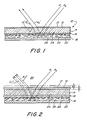
- FIG. 1 is a side view of a recording assembly 10 which is constructed according to the present invention. While the present embodiment shows the recording assembly 10 with a flat configuration, it should be understood that other configurations, such as a curved one, are contemplated.
- the recording assembly 10 is a module that includes at the bottommost portion thereof, when viewed from FIG. 1, a reflective element or mirror 20.
- the mirror 20 has at its top surface thereof, when viewed from FIG. 1, a reflective surface 22 that serves to reflect light rays which are designated as A1, A2.
- a reservoir of an index matching fluid 18 is disposed immediately above and in contact with the reflective surface 22.
- the fluid 18 can be of any suitable and well-known matching fluid commonly used in holographic recording modules, such as xylene or mineral oil.
- the fluid 18 may be an optical grade mineral oil or a microscope immersion oil.
- the reservoir of index matching fluid 18 has a thickness of approximately 0.20 to 0.25 inches. With a thickness of less than 0.01 inches for the fluid 18, controlled recording is difficult. More than 0.25 inches may present problems of index variations.
- a recording medium or film 16 is positioned immediately adjacent a top side of the reservoir of index matching fluid 18.
- the recording medium 16 includes a top surface 24 and a bottom surface 26, and is made of any suitable, well-known recording film material for holograms.
- the recording material 16 is made of dichromated gelatin.
- the thickness of the recording medium 16 in this particular embodiment is approximately 0.001 inches, but can vary.
- a substrate 14 supports the recording medium 16 at the upper surface 24 thereof. While the substrate 14 is made of glass in this particular embodiment, it can be appreciated by those skilled in the art that other materials, such as semiconductor materials, can also be used, and which are dependent upon the wavelength of the radiation. The thickness of the substrate 14 is approximately 0.25 inches in this embodiment, but can vary.
- An absorbent or transparent member 12 is supported on a side of the substrate 14 which is opposite the recording medium 16.
- the absorbent member 12 is, during the recording period, out of moisture equilibrium with a surrounding environment 28.
- the absorbent member 12 is made of undichromated gelatin and has a thickness of about 10 to 50 micrometers.
- the present invention contemplates that the absorbent member 12 may not be transparent and may contain a dye therein, such as very fine carbon that is water soluble and miscible with the gelatin (or other material) in a solvent or a wavelength dependent dye such as methyl orange, which might be used for a green-blue exposure range. With a dye, spurious reflections are decreased from absorption by the dye material, which reflections particularly occur at an air interface 13 of the member 12.
- a greater reduction of noise or spurious holograms is achieved than without a dye.
- Primary light beams such as A1, A2 (FIG. 1) go through the member 12 once, and may then exit the assembly as beams A1′, A2′.
- a noise beam such as A1 ⁇ (FIG. 1), effectively goes through the member 12 three times. If, for example, absorption loss from the recording medium 16 and mirror 20 are ignored, and a reflection factor at the surface 13 of about 4% is assumed, the noise beam A1 ⁇ will be about 3.2% of the primary beam A1 without a dye. With the addition of a dye, the primary beam A1 may need to be twice as bright to overcome the 50% absorption factor of the dye, but then the noise beam A1 ⁇ is then reduced to about 0.8% of the primary beam at the medium 16.
- a gelatin film such as the absorbent member 12 can shrink, and the shrinkage appears to occur in four distinct mechanisms.
- One mechanism is a loss of water. Shrinkage of the gelatin due to loss of water is nearly equivalent to the volume of water lost. The water can occur as interstitial or as fairly loosely bound water. In either case, the bulk of the water comes off fairly rapidly (less than one day at 60°C).
- the chemical composition and structure of the gelatin can vary from one sample to another. Accordingly, the rate at which a gelatin layer (i.e., the absorbent member 12) can lose water, or even absorb water, can differ from one type of gelatin to another.
- FIG. 2 depicts the manner in which the present invention takes advantage of the ability of gelatin to absorb and lose water.
- the absorbent member 12, which is made of gelatin, is shown in hatched lines having a thickness S.
- the thickness S is representative of the thickness of the absorbent member 12 in a static state. In such a state, the absorbent member 12 is neither absorbing nor losing moisture in a net amount with respect to the environment 28. Consequently, the thickness of the absorbent member 12 remains stable or static.
- the absorbent member 12 when the absorbent member 12 is out of moisture equilibrium with the environment 28, the absorbent member 12 may swell by the absorption of water and its thickness would increase by an amount designated by ⁇ S.
- the change in thickness of ⁇ S is represented in FIG. 2 by the phantom lines above the cross-hatched lines that represent the absorbent member 12 in a static state.
- ⁇ S the absorbent member 12 absorbs water and leaves its static state, it increases in thickness by an amount ⁇ S.
- the absorbent member 12 when the absorbent member 12 loses water to the environment, the absorbent member 12 will be represented by the aggregate of the phantom lines and the cross-hatched lines in FIG. 2. Thus, when the absorbent member loses water to the environment 28, the absorbent member becomes reduced in thickness by an amount represented by ⁇ S. When the absorbent member 12 finally reaches moisture equilibrium, it will then be in the static state which is represented by the cross-hatched lines.
- the present invention utilizes the changes in thickness through a distance ⁇ S to produce a phase shift of a light moving through the recording assembly 10.
- a phase shift of the light passing through the recording assembly 10 in an amount of approximately one-half wavelength will substantially eliminate the otherwise present spurious holograms, while leaving the desired hologram with sufficient clarity.
- the phase shift is depicted in FIG. 2 by rays A1°, A2°.
- the production of phase shift and consequent blurring of noise holograms in similar contexts, which is applicable herein, is generally described in U.S. Patent No. 4,458,977, 4,458,978, and 4,456,328.
- a change in thickness of about 1.5% will produce the needed phase shift.
- the change may range from about 0.5% for thick members and to about 2.5% for thin members.
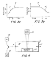
- FIGS. 3(a), (b) graphically illustrate, for purposes of examples, changes in a thickness S in an absorbent member 12. The figures only seek to depict what might be considered model situations.
- a moisture curve M is shown for an absorbent member 12 absorbing moisture.
- FIG. 3(b) shows another moisture curve M′, which is representative of an absorbent member 12 shrinking as it loses moisture.
- the thickness of the absorbent member 12 increases from a thickness S1 to a thickness S2 in a substantially linear fashion.
- This substantially linear occurrence on a portion of the moisture curve M is denoted by the reference letter E.
- the absorbent member 12 is just beginning to increase in thickness, and thus the curve is significantly less linear than the portion E.
- the portion of the curve M on the right side of the curve E when viewed from FIG. 3(a), represents a time during which the absorbent member 12 is becoming saturated or in moisture equilibrium with the environment 28. Again, the right side of the curve M is significantly less linear than the portion E.
- a thickness of an absorbent member 12 decreases from a thickness S1′ to a thickness S2′.
- the portions of the moisture curve M′ on either side of the portion E′ represent nonlinear changes of the thickness S over time.
- the exposure of the recording medium 16 is limited to the time represented by the curves E, E′, respectively.
- the phase shift of the reflections in the recording assembly 10 is generally linear over time. Consequently, the blurring or smearing out of the spurious holograms is substantially linear over time. If, however, the exposure were to occur outside of the portions E, E′, the thickness change would not be linear, and thus the phase shift would not be linear. In turn, this would cause the spurious holograms to be unevenly blurred or smeared out, and thus actually result in the creation of spurious holograms.
- FIGs. 3(a), (b) are merely illustrations of what might be considered a model absorbent member 12.
- a 300 bloom strength, porkskin type A gelatin was used as the absorbent member 12.
- An increase of relative humidity from 0 to 22% produced a swelling rate of approximately 0.22 wavelengths per minute for the same member 12.
- a decrease in relative humidity of this particular member did not give a substantially linear shrinkage rate from 22 to 0% relative humidity.
- the material out of which the absorbent member 12 is constructed can be selected to provide a greater tendency or lesser tendency to absorb and lose moisture. Such a characteristic may be important for the particular recording assembly into which the absorbent member 12 is incorporated, and the length of time over which the exposure is expected to occur. With very short exposure times, it may be necessary to utilize an absorbent member 12 that quickly absorbs or loses moisture. On the other hand, with a long exposure time, it may be necessary to utilize a different material for the absorbent member 12 that more slowly absorbs or loses moisture.
- a light source 40 produces the light rays A1, A2 which are shown in FIGS. 1, 2.
- the light rays impinge upon the recording assembly 10 which is placed in a sealed housing 30.
- the housing 30 controls the relative humidity of the environment 28 surrounding the recording assembly 10.
- a nitrogen gas source 36 can introduce nitrogen through an inlet 32 of the housing 30.
- the nitrogen gas is allowed to pass over the recording assembly 10 and thereby draw moisture out of the environment 28 through an outlet 34.
- a moisture gradient is set up such that the absorbent member 12 tends to lose moisture to the environment 28.
- a moisture source 38 can pump moisture through the inlet 32 and into the environment 28 to again create a moisture gradient. With a higher relative moisture in the environment 28, the absorbent member 12 can absorb moisture.
- the absorbent member 12 in the recording assembly 10 can be forced to absorb water or lose water, as desired.
- the absorbent member 12 will change in thickness in a substantially linear relationship over a specific period of time, and during that time the exposure of the recording medium 16 can occur.
- the linear change in thickness produces a linear phase shift in reflections in the recording assembly 10 and substantially blurs out spurious holograms while leaving the desired hologram intact.
Abstract
Description
- This invention generally relates to a system and method for reducing noise holograms and, more specifically, to an improved system and method for inducing phase shifts of reflective light during construction of the primary hologram.
- High quality holographic optical elements are used in defraction optics display systems, such as head up displays (HUDs), for advanced aircraft, helmet mounted displays, laser protective devices, narrow band reflective filters, and holographic high gain screens for simulators. These are only a few of the many uses of high quality reflective holograms.
- One of the critical problems in defraction optic display systems utilizing a replicated hologram has been a degradation of the holographic images as a result of the effects of spurious reflection in transmission hologram recordings that are frequently generated during the holographic replication process. Perhaps the most damaging spurious noise holograms are generated by reflections from surfaces which are interfaces of materials of different indexes of refraction, such as air/glass interfaces of the transparent surfaces of a recording cover plate, a hologram substrate, the recording medium itself, and optical elements used to generate the recording beams. These reflections can combine with the primary holographic beams at the recording film to form spurious reflection holograms, when the beams are in the opposite direction, and spurious transmission holograms when the beams are in the same direction. A subsequent display system using this hologram will be degraded by ghost images from the spurious reflection hologram recordings, and rainbow-like flair patterns from the spurious transmission hologram recordings.
- The prior art has attempted to solve these problems in several different ways. A simple approach has been to form the hologram with energy beams that strike the recording material surfaces at Brewster's angle, at which reflections are at a minimum. This method has very limited application because in general the incident angle is set by the desired holographic function, and is not a variable that one can select at will.
- Another approach has been to reduce the spurious reflections by attempting to match the indexes of refraction at the different surface interfaces with an index matching fluid, such as a mineral oil. The entire recording module is immersed in an index of refraction matching oil bath. The shape of the container is then designed so that surface reflections are directed away from the recording material. For many optical configurations, such a shape does not exist. Furthermore, the phase instability of the optical paths in oil degrade the desired hologram. Also, the problems of stabilizing the oil after each plate change, the need to frequently clean the oil of impurities, and the delays in handling the volume of oil needed all make this method unsuitable for production.
- More sophisticated approaches are disclosed in U.S. Patent Nos. 4,458,977, 4,458,978, and 4,456,328, in which spurious holograms caused by glass/air interfaces are eliminated by moving an outside cover plate to change the phase of the reflected rays relative to the primary beams during the recording period. Thereby, spurious holograms are not formed. For these approaches that use a moving cover plate, the rate of movement or phase change is a function of the exposure time which depends on the sensitivity of the recording medium. The total movement must provide a phase change of at least one half wavelength in the reflected spurious hologram beams to nullify or "smear out" any spurious interference patterns that would otherwise be recorded. While those systems have advantages over the prior art, they still have certain disadvantages. For example, the drivers to move the cover plate take time to adjust, calibrate, and test. The complete apparatus in complex to set up, needs long stabilization time, and has many modes of potential failure to decrease yield.
- Another attempt to suppress spurious holograms is disclosed in U.S. Patent No. 3,601,017. Therein, an immersion liquid is applied to either the surface of the recording medium or the surface of a transparent support member, which surface is remote from the direction of light incidence. The thickness of the immersion agent layer is varied over time during an exposure by evaporation or, when it is not so readily evaporated, by generating acoustic or surface waves which, during their reflection, directionally modulate the wave field in the liquid. Preferably, the transparent immersion liquid is O-xylene. This system also has drawbacks, including the fact that the evaporating liquid is not a good optical surface. Further, the variation in thickness would not appear to be highly regulated, particularly when using generated waves.
- A need still exists in the technology to provide an improved system and method for producing a high quality hologram that has minimal spurious holograms and at the same time can be produced in an economical and efficient manner.
- The present invention seeks to overcome the disadvantages found in the prior art by providing a recording assembly that includes a mirror positioned at the bottom of the recording assembly, and a reservoir of index matching fluid is adjacent to a reflective surface of the mirror. A recording medium is then placed on a side of the reservoir opposite the mirror. A substrate supports the recording medium, as well as an absorbent, transparent member on a side of the substrate opposite the recording medium. The absorbent member is out of moisture equilibrium with the surrounding environment. Thereby, the absorbent, transparent member can either absorb moisture from the environment or release it into the environment, depending upon the moisture differential between the transparent member and the environment. During the time that the absorbent, transparent member is either absorbing or releasing moisture, preferably at a constant rate, the recording assembly can be recording an interference pattern in the recording medium.
- By steadily increasing or decreasing the thickness of the absorbent member, the interference fringes or patterns which constitute the spurious holograms are blurred to an extent sufficient to practically remove the interference caused by the spurious hologram. At the same time, the desired hologram is not significantly blurred and remains sufficiently clear for the needed purpose. Specifically, the blurring is caused by the motion of the interference pattern in space as a result of one reflection surface moving. The process of blurring the spurious holograms continues during the recording time period and, during such time, the rate of expansion or contraction of the absorbent member remains substantially constant.
- The objects of the present invention can best be seen from an examination of the specification, claims, and drawings hereto.
-
- FIG. 1 depicts the recording of a hologram according to the present invention wherein an absorbent or transparent member in the recording assembly is static;
- FIG. 2 discloses a recording assembly according to the present invention wherein an absorbent member has been reduced or increased in thickness during the recording of a hologram;
- FIG. 3(a) is a graph of increasing thickness of the absorbent member over time according to the present invention;
- FIG. 3(b) is a graph of decreasing thickness of the absorbent member over time according to the present invention; and
- FIG. 4 depicts an exposure system for the hologram assembly according to the present invention.
- The following description is provided to enable any person skilled in the art to which the present invention pertains, or with which it is most nearly connected, to make and use the same, and sets forth the best mode contemplated by the inventor of carrying out his invention. Various modifications, however, will remain readily apparent to those skilled in the art, since the generic principles of the present invention have been defined herein specifically to provide an improved system for reducing noise holograms.
- FIG. 1 is a side view of a recording assembly 10 which is constructed according to the present invention. While the present embodiment shows the recording assembly 10 with a flat configuration, it should be understood that other configurations, such as a curved one, are contemplated. The recording assembly 10 is a module that includes at the bottommost portion thereof, when viewed from FIG. 1, a reflective element or
mirror 20. Themirror 20 has at its top surface thereof, when viewed from FIG. 1, areflective surface 22 that serves to reflect light rays which are designated as A₁, A₂. A reservoir of anindex matching fluid 18 is disposed immediately above and in contact with thereflective surface 22. Thefluid 18 can be of any suitable and well-known matching fluid commonly used in holographic recording modules, such as xylene or mineral oil. For example, thefluid 18 may be an optical grade mineral oil or a microscope immersion oil. In this particular embodiment, with the recording assembly having an overall thickness of about 0.50 to 0.75 inches, the reservoir ofindex matching fluid 18 has a thickness of approximately 0.20 to 0.25 inches. With a thickness of less than 0.01 inches for thefluid 18, controlled recording is difficult. More than 0.25 inches may present problems of index variations. - A recording medium or
film 16 is positioned immediately adjacent a top side of the reservoir ofindex matching fluid 18. Therecording medium 16 includes atop surface 24 and abottom surface 26, and is made of any suitable, well-known recording film material for holograms. In this particular embodiment, therecording material 16 is made of dichromated gelatin. The thickness of therecording medium 16 in this particular embodiment is approximately 0.001 inches, but can vary. - A
substrate 14 supports therecording medium 16 at theupper surface 24 thereof. While thesubstrate 14 is made of glass in this particular embodiment, it can be appreciated by those skilled in the art that other materials, such as semiconductor materials, can also be used, and which are dependent upon the wavelength of the radiation. The thickness of thesubstrate 14 is approximately 0.25 inches in this embodiment, but can vary. - An absorbent or
transparent member 12 is supported on a side of thesubstrate 14 which is opposite therecording medium 16. Theabsorbent member 12 is, during the recording period, out of moisture equilibrium with a surroundingenvironment 28. In this particular embodiment, theabsorbent member 12 is made of undichromated gelatin and has a thickness of about 10 to 50 micrometers. The present invention contemplates that theabsorbent member 12 may not be transparent and may contain a dye therein, such as very fine carbon that is water soluble and miscible with the gelatin (or other material) in a solvent or a wavelength dependent dye such as methyl orange, which might be used for a green-blue exposure range. With a dye, spurious reflections are decreased from absorption by the dye material, which reflections particularly occur at anair interface 13 of themember 12. - In the event that a dye is in the
absorbent member 12, a greater reduction of noise or spurious holograms is achieved than without a dye. This is due to the following. Primary light beams, such as A₁, A₂ (FIG. 1) go through themember 12 once, and may then exit the assembly as beams A₁′, A₂′. In contrast, a noise beam, such as A₁˝ (FIG. 1), effectively goes through themember 12 three times. If, for example, absorption loss from therecording medium 16 andmirror 20 are ignored, and a reflection factor at thesurface 13 of about 4% is assumed, the noise beam A₁˝ will be about 3.2% of the primary beam A₁ without a dye. With the addition of a dye, the primary beam A₁ may need to be twice as bright to overcome the 50% absorption factor of the dye, but then the noise beam A₁˝ is then reduced to about 0.8% of the primary beam at the medium 16. - As is known in the art, a gelatin film such as the
absorbent member 12 can shrink, and the shrinkage appears to occur in four distinct mechanisms. One mechanism is a loss of water. Shrinkage of the gelatin due to loss of water is nearly equivalent to the volume of water lost. The water can occur as interstitial or as fairly loosely bound water. In either case, the bulk of the water comes off fairly rapidly (less than one day at 60°C). As can be appreciated, because of the natural origin of the basic gelatin material, the chemical composition and structure of the gelatin can vary from one sample to another. Accordingly, the rate at which a gelatin layer (i.e., the absorbent member 12) can lose water, or even absorb water, can differ from one type of gelatin to another. - FIG. 2 depicts the manner in which the present invention takes advantage of the ability of gelatin to absorb and lose water. The
absorbent member 12, which is made of gelatin, is shown in hatched lines having a thickness S. The thickness S is representative of the thickness of theabsorbent member 12 in a static state. In such a state, theabsorbent member 12 is neither absorbing nor losing moisture in a net amount with respect to theenvironment 28. Consequently, the thickness of theabsorbent member 12 remains stable or static. - However, when the
absorbent member 12 is out of moisture equilibrium with theenvironment 28, theabsorbent member 12 may swell by the absorption of water and its thickness would increase by an amount designated by ΔS. The change in thickness of ΔS is represented in FIG. 2 by the phantom lines above the cross-hatched lines that represent theabsorbent member 12 in a static state. Thus, as theabsorbent member 12 absorbs water and leaves its static state, it increases in thickness by an amount ΔS. - On the other hand, when the
absorbent member 12 loses water to the environment, theabsorbent member 12 will be represented by the aggregate of the phantom lines and the cross-hatched lines in FIG. 2. Thus, when the absorbent member loses water to theenvironment 28, the absorbent member becomes reduced in thickness by an amount represented by ΔS. When theabsorbent member 12 finally reaches moisture equilibrium, it will then be in the static state which is represented by the cross-hatched lines. - The present invention utilizes the changes in thickness through a distance ΔS to produce a phase shift of a light moving through the recording assembly 10. In particular, a phase shift of the light passing through the recording assembly 10 in an amount of approximately one-half wavelength will substantially eliminate the otherwise present spurious holograms, while leaving the desired hologram with sufficient clarity. The phase shift is depicted in FIG. 2 by rays A₁°, A₂°. (The production of phase shift and consequent blurring of noise holograms in similar contexts, which is applicable herein, is generally described in U.S. Patent No. 4,458,977, 4,458,978, and 4,456,328.) With the above size parameters in this particular embodiment, a change in thickness of about 1.5% will produce the needed phase shift. The change may range from about 0.5% for thick members and to about 2.5% for thin members.
- FIGS. 3(a), (b) graphically illustrate, for purposes of examples, changes in a thickness S in an
absorbent member 12. The figures only seek to depict what might be considered model situations. In FIG. 3(a), a moisture curve M is shown for anabsorbent member 12 absorbing moisture. FIG. 3(b) shows another moisture curve M′, which is representative of anabsorbent member 12 shrinking as it loses moisture. - In FIG. 3(a), between a time t₁ and a time t₂, the thickness of the
absorbent member 12 increases from a thickness S₁ to a thickness S₂ in a substantially linear fashion. This substantially linear occurrence on a portion of the moisture curve M is denoted by the reference letter E. To the left side of the curve E, when viewed from FIG. 3(a), theabsorbent member 12 is just beginning to increase in thickness, and thus the curve is significantly less linear than the portion E. Similarly, the portion of the curve M on the right side of the curve E, when viewed from FIG. 3(a), represents a time during which theabsorbent member 12 is becoming saturated or in moisture equilibrium with theenvironment 28. Again, the right side of the curve M is significantly less linear than the portion E. - Referring to FIG. 3(b), between a time t₁′ and a time t₂′, a thickness of an
absorbent member 12 decreases from a thickness S₁′ to a thickness S₂′. This represents a substantially linear decrease in thickness over time, and is indicated as E′ in a portion of the moisture curve M′. As in the case shown in FIG. 3(a), the portions of the moisture curve M′ on either side of the portion E′ represent nonlinear changes of the thickness S over time. - In either instance represented by FIGS. 3(a), (b), the exposure of the
recording medium 16 is limited to the time represented by the curves E, E′, respectively. During those time periods, since the thickness S of theabsorbent member 12 is linearly changing over time, the phase shift of the reflections in the recording assembly 10 is generally linear over time. Consequently, the blurring or smearing out of the spurious holograms is substantially linear over time. If, however, the exposure were to occur outside of the portions E, E′, the thickness change would not be linear, and thus the phase shift would not be linear. In turn, this would cause the spurious holograms to be unevenly blurred or smeared out, and thus actually result in the creation of spurious holograms. - As was noted above, FIGs. 3(a), (b) are merely illustrations of what might be considered a model
absorbent member 12. Experimentally, a 300 bloom strength, porkskin type A gelatin was used as theabsorbent member 12. Test results indicated that an increase in relative humidity from 0 to 5% produces a swelling rate that is nearly linear over a 30-minute period of time. This is generally equivalent to 0.05 wavelengths of argon laser light (5145 Å) per minute when theabsorbent member 12 is 50 microns thick. An increase of relative humidity from 0 to 22% produced a swelling rate of approximately 0.22 wavelengths per minute for thesame member 12. A decrease in relative humidity of this particular member did not give a substantially linear shrinkage rate from 22 to 0% relative humidity. - It can be appreciated by those skilled in the art that the material out of which the
absorbent member 12 is constructed can be selected to provide a greater tendency or lesser tendency to absorb and lose moisture. Such a characteristic may be important for the particular recording assembly into which theabsorbent member 12 is incorporated, and the length of time over which the exposure is expected to occur. With very short exposure times, it may be necessary to utilize anabsorbent member 12 that quickly absorbs or loses moisture. On the other hand, with a long exposure time, it may be necessary to utilize a different material for theabsorbent member 12 that more slowly absorbs or loses moisture. - In operation, and as shown in FIG. 4, a
light source 40 produces the light rays A₁, A₂ which are shown in FIGS. 1, 2. The light rays impinge upon the recording assembly 10 which is placed in a sealedhousing 30. Thehousing 30 controls the relative humidity of theenvironment 28 surrounding the recording assembly 10. In this particular embodiment, anitrogen gas source 36 can introduce nitrogen through aninlet 32 of thehousing 30. The nitrogen gas is allowed to pass over the recording assembly 10 and thereby draw moisture out of theenvironment 28 through anoutlet 34. As moisture is drawn out of thehousing 30, a moisture gradient is set up such that theabsorbent member 12 tends to lose moisture to theenvironment 28. When theabsorbent member 12 must absorb moisture, amoisture source 38 can pump moisture through theinlet 32 and into theenvironment 28 to again create a moisture gradient. With a higher relative moisture in theenvironment 28, theabsorbent member 12 can absorb moisture. - The result is that the
absorbent member 12 in the recording assembly 10 can be forced to absorb water or lose water, as desired. In so doing, theabsorbent member 12 will change in thickness in a substantially linear relationship over a specific period of time, and during that time the exposure of therecording medium 16 can occur. The linear change in thickness produces a linear phase shift in reflections in the recording assembly 10 and substantially blurs out spurious holograms while leaving the desired hologram intact. - The above only represents particular embodiments of the present invention, and it is contemplated that various modifications to the above can be effected but nevertheless come within the scope of the present invention as defined by the claims.
Claims (12)
an absorbent member (12) positioned relative to said exposure beam (A₁, A₂) and fixed on a surface of said substrate (14), said absorbent member (12) capable of being variable in thickness in two directions, which variation occurs during an exposure time of said recording medium.
a layer (12) of absorbent material positioned on a surface of the substrate (14), said absorbent material being directly incident to said exposure beam (A₁, A₂); and
means for communicating a fluid to said absorbent material to alter a layer thickness (S) during an exposure time (t) to said recording medium (16).
first means (40) for producing a exposure beam (A₁, A₂);
a transparent substrate (14) having a first side and an oppositely facing second side;
an absorbent member (12) on the first side of said substrate (14) and variable in thickness (S) upon a continuing change towards moisture equilibrium with a surrounding environment (28);
a recording material (16) on the second side of said substrate (14);
second means (20) for reflecting said exposure beams (A₁, A₂) towards said recording material (16); and
third means (18) for matching indexes of refraction of beams (A₁, A₂), said third means (18) being intermediate said second means (20) and said recording material (16).
Applications Claiming Priority (2)
| Application Number | Priority Date | Filing Date | Title |
|---|---|---|---|
| US07/226,593 US4953923A (en) | 1988-08-01 | 1988-08-01 | System for reducing noise holograms |
| US226593 | 1994-04-11 |
Publications (3)
| Publication Number | Publication Date |
|---|---|
| EP0353602A2 true EP0353602A2 (en) | 1990-02-07 |
| EP0353602A3 EP0353602A3 (en) | 1991-08-28 |
| EP0353602B1 EP0353602B1 (en) | 1995-03-08 |
Family
ID=22849552
Family Applications (1)
| Application Number | Title | Priority Date | Filing Date |
|---|---|---|---|
| EP89113732A Expired - Lifetime EP0353602B1 (en) | 1988-08-01 | 1989-07-25 | A system for reducing noise holograms |
Country Status (8)
| Country | Link |
|---|---|
| US (1) | US4953923A (en) |
| EP (1) | EP0353602B1 (en) |
| JP (1) | JPH0673054B2 (en) |
| CA (1) | CA1321715C (en) |
| DE (1) | DE68921520T2 (en) |
| DK (1) | DK375289A (en) |
| ES (1) | ES2014371A6 (en) |
| IL (1) | IL90801A (en) |
Cited By (2)
| Publication number | Priority date | Publication date | Assignee | Title |
|---|---|---|---|---|
| EP0415245A2 (en) * | 1989-08-31 | 1991-03-06 | Hughes Aircraft Company | Holographic exposure system to reduce spurious hologram noise |
| EP0536763B1 (en) * | 1991-10-09 | 1999-03-17 | Denso Corporation | Hologram |
Families Citing this family (10)
| Publication number | Priority date | Publication date | Assignee | Title |
|---|---|---|---|---|
| US5726782A (en) * | 1991-10-09 | 1998-03-10 | Nippondenso Co., Ltd. | Hologram and method of fabricating |
| US5633100A (en) * | 1991-11-27 | 1997-05-27 | E. I. Du Pont De Nemours And Company | Holographic imaging using filters |
| EP0585941A3 (en) * | 1992-09-03 | 1994-09-21 | Nippon Denso Co | Process for making holograms and holography device |
| US5672448A (en) * | 1992-12-29 | 1997-09-30 | Nippondenso Co., Ltd. | Multi-exposure system for hologram |
| US5555108A (en) * | 1994-08-31 | 1996-09-10 | Hughes Electronics | Holographic exposure prism |
| KR100227179B1 (en) * | 1997-04-11 | 1999-10-15 | 박호군 | The manufacture apparatus for reflection type holographic optic element of high quality |
| JP4404282B2 (en) * | 1999-03-19 | 2010-01-27 | 大日本印刷株式会社 | Method and apparatus for producing hologram imaging dry plate |
| KR100416479B1 (en) * | 2000-07-29 | 2004-01-31 | (주)맥스소프트 | Incoherent holographic three-dimensional display device |
| KR100670457B1 (en) | 2004-06-30 | 2007-01-16 | 엘지전자 주식회사 | Data storage device |
| US8614842B2 (en) | 2011-11-14 | 2013-12-24 | Prism Solar Technologies Incorporated | Volume hologram replicator for transmission type gratings |
Citations (4)
| Publication number | Priority date | Publication date | Assignee | Title |
|---|---|---|---|---|
| US3601017A (en) * | 1968-11-23 | 1971-08-24 | Philips Corp | Method of suppressing interference fringes in photosensitive material |
| US4456328A (en) * | 1981-06-01 | 1984-06-26 | Hughes Aircraft Company | Systems for forming improved diffusion holograms |
| US4458977A (en) * | 1981-06-01 | 1984-07-10 | Hughes Aircraft Company | Systems for forming improved reflection holograms with a single beam |
| US4458978A (en) * | 1981-06-01 | 1984-07-10 | Hughes Aircraft Company | Double beam systems for forming improved holograms |
Family Cites Families (1)
| Publication number | Priority date | Publication date | Assignee | Title |
|---|---|---|---|---|
| JPS6230631A (en) * | 1985-07-31 | 1987-02-09 | Seiko Epson Corp | Production of glass article |
-
1988
- 1988-08-01 US US07/226,593 patent/US4953923A/en not_active Expired - Lifetime
-
1989
- 1989-06-29 IL IL90801A patent/IL90801A/en not_active IP Right Cessation
- 1989-07-13 CA CA000605625A patent/CA1321715C/en not_active Expired - Fee Related
- 1989-07-25 EP EP89113732A patent/EP0353602B1/en not_active Expired - Lifetime
- 1989-07-25 DE DE68921520T patent/DE68921520T2/en not_active Expired - Fee Related
- 1989-07-31 ES ES8902710A patent/ES2014371A6/en not_active Expired - Fee Related
- 1989-07-31 DK DK375289A patent/DK375289A/en not_active Application Discontinuation
- 1989-08-01 JP JP1198097A patent/JPH0673054B2/en not_active Expired - Lifetime
Patent Citations (4)
| Publication number | Priority date | Publication date | Assignee | Title |
|---|---|---|---|---|
| US3601017A (en) * | 1968-11-23 | 1971-08-24 | Philips Corp | Method of suppressing interference fringes in photosensitive material |
| US4456328A (en) * | 1981-06-01 | 1984-06-26 | Hughes Aircraft Company | Systems for forming improved diffusion holograms |
| US4458977A (en) * | 1981-06-01 | 1984-07-10 | Hughes Aircraft Company | Systems for forming improved reflection holograms with a single beam |
| US4458978A (en) * | 1981-06-01 | 1984-07-10 | Hughes Aircraft Company | Double beam systems for forming improved holograms |
Cited By (3)
| Publication number | Priority date | Publication date | Assignee | Title |
|---|---|---|---|---|
| EP0415245A2 (en) * | 1989-08-31 | 1991-03-06 | Hughes Aircraft Company | Holographic exposure system to reduce spurious hologram noise |
| EP0415245A3 (en) * | 1989-08-31 | 1992-04-22 | Hughes Aircraft Company | Holographic exposure system to reduce spurious hologram noise |
| EP0536763B1 (en) * | 1991-10-09 | 1999-03-17 | Denso Corporation | Hologram |
Also Published As
| Publication number | Publication date |
|---|---|
| DK375289A (en) | 1990-02-02 |
| DE68921520D1 (en) | 1995-04-13 |
| DK375289D0 (en) | 1989-07-31 |
| IL90801A0 (en) | 1990-01-18 |
| JPH0274979A (en) | 1990-03-14 |
| CA1321715C (en) | 1993-08-31 |
| EP0353602A3 (en) | 1991-08-28 |
| DE68921520T2 (en) | 1995-07-20 |
| ES2014371A6 (en) | 1990-07-01 |
| EP0353602B1 (en) | 1995-03-08 |
| JPH0673054B2 (en) | 1994-09-14 |
| US4953923A (en) | 1990-09-04 |
| IL90801A (en) | 1993-01-31 |
Similar Documents
| Publication | Publication Date | Title |
|---|---|---|
| US4960311A (en) | Holographic exposure system for computer generated holograms | |
| EP0353602B1 (en) | A system for reducing noise holograms | |
| Chang | Dichromated gelatin holograms and their applications | |
| US4799746A (en) | Efficient holograms and method for making same | |
| US5491570A (en) | Methods and devices for using photorefractive materials at infrared wavelengths | |
| US4988151A (en) | Method for making edge faded holograms | |
| EP0536763B1 (en) | Hologram | |
| US5633100A (en) | Holographic imaging using filters | |
| US5477347A (en) | Method and apparatus for isolating data storage regions in a thin holographic storage media | |
| US4458977A (en) | Systems for forming improved reflection holograms with a single beam | |
| US4815800A (en) | Flare reduction in holograms | |
| WO1984002197A1 (en) | Diffraction head up display solar radiation filter | |
| CA2065368A1 (en) | Methods of and apparatus for manipulating electromagnetic phenomenon | |
| US4456328A (en) | Systems for forming improved diffusion holograms | |
| EP0415245B1 (en) | Holographic exposure system to reduce spurious hologram noise | |
| JP2863533B2 (en) | Holographic mirror manufacturing method | |
| US5315417A (en) | Low noise transmission holographic optical element | |
| US4978183A (en) | Holographic optic element collimator and method and apparatus for manufacture | |
| Amodei et al. | Holograms in Thin Bismuth Films | |
| EP0214226B1 (en) | Process for improving holographic efficiency | |
| US5105287A (en) | Reduction of holographic noise with short laser pulses | |
| US5052764A (en) | System and method for forming a holographic exposure with a simulated source | |
| US5052765A (en) | Scanning fiber optic holographic exposure and feedback system | |
| Ando et al. | Holographic data storage media employing phase-change reflector | |
| Cowan | Holography utilizing surface plasmon resonances |
Legal Events
| Date | Code | Title | Description |
|---|---|---|---|
| PUAI | Public reference made under article 153(3) epc to a published international application that has entered the european phase |
Free format text: ORIGINAL CODE: 0009012 |
|
| 17P | Request for examination filed |
Effective date: 19890822 |
|
| AK | Designated contracting states |
Kind code of ref document: A2 Designated state(s): DE FR GB IT NL SE |
|
| PUAL | Search report despatched |
Free format text: ORIGINAL CODE: 0009013 |
|
| AK | Designated contracting states |
Kind code of ref document: A3 Designated state(s): DE FR GB IT NL SE |
|
| 17Q | First examination report despatched |
Effective date: 19930602 |
|
| GRAA | (expected) grant |
Free format text: ORIGINAL CODE: 0009210 |
|
| ITF | It: translation for a ep patent filed |
Owner name: SOCIETA' ITALIANA BREVETTI S.P.A. |
|
| AK | Designated contracting states |
Kind code of ref document: B1 Designated state(s): DE FR GB IT NL SE |
|
| REF | Corresponds to: |
Ref document number: 68921520 Country of ref document: DE Date of ref document: 19950413 |
|
| ET | Fr: translation filed | ||
| PLBE | No opposition filed within time limit |
Free format text: ORIGINAL CODE: 0009261 |
|
| STAA | Information on the status of an ep patent application or granted ep patent |
Free format text: STATUS: NO OPPOSITION FILED WITHIN TIME LIMIT |
|
| 26N | No opposition filed | ||
| PGFP | Annual fee paid to national office [announced via postgrant information from national office to epo] |
Ref country code: FR Payment date: 19970613 Year of fee payment: 9 |
|
| PGFP | Annual fee paid to national office [announced via postgrant information from national office to epo] |
Ref country code: SE Payment date: 19970618 Year of fee payment: 9 |
|
| PGFP | Annual fee paid to national office [announced via postgrant information from national office to epo] |
Ref country code: GB Payment date: 19970620 Year of fee payment: 9 |
|
| PGFP | Annual fee paid to national office [announced via postgrant information from national office to epo] |
Ref country code: DE Payment date: 19970623 Year of fee payment: 9 |
|
| PGFP | Annual fee paid to national office [announced via postgrant information from national office to epo] |
Ref country code: NL Payment date: 19970630 Year of fee payment: 9 |
|
| PG25 | Lapsed in a contracting state [announced via postgrant information from national office to epo] |
Ref country code: GB Free format text: LAPSE BECAUSE OF NON-PAYMENT OF DUE FEES Effective date: 19980725 |
|
| PG25 | Lapsed in a contracting state [announced via postgrant information from national office to epo] |
Ref country code: SE Free format text: LAPSE BECAUSE OF NON-PAYMENT OF DUE FEES Effective date: 19980726 |
|
| PG25 | Lapsed in a contracting state [announced via postgrant information from national office to epo] |
Ref country code: NL Free format text: LAPSE BECAUSE OF NON-PAYMENT OF DUE FEES Effective date: 19990201 |
|
| GBPC | Gb: european patent ceased through non-payment of renewal fee |
Effective date: 19980725 |
|
| EUG | Se: european patent has lapsed |
Ref document number: 89113732.5 |
|
| PG25 | Lapsed in a contracting state [announced via postgrant information from national office to epo] |
Ref country code: FR Free format text: LAPSE BECAUSE OF NON-PAYMENT OF DUE FEES Effective date: 19990331 |
|
| NLV4 | Nl: lapsed or anulled due to non-payment of the annual fee |
Effective date: 19990201 |
|
| PG25 | Lapsed in a contracting state [announced via postgrant information from national office to epo] |
Ref country code: DE Free format text: LAPSE BECAUSE OF NON-PAYMENT OF DUE FEES Effective date: 19990501 |
|
| REG | Reference to a national code |
Ref country code: FR Ref legal event code: ST |
|
| PG25 | Lapsed in a contracting state [announced via postgrant information from national office to epo] |
Ref country code: IT Free format text: LAPSE BECAUSE OF NON-PAYMENT OF DUE FEES;WARNING: LAPSES OF ITALIAN PATENTS WITH EFFECTIVE DATE BEFORE 2007 MAY HAVE OCCURRED AT ANY TIME BEFORE 2007. THE CORRECT EFFECTIVE DATE MAY BE DIFFERENT FROM THE ONE RECORDED. Effective date: 20050725 |