EP0353498A2 - Compressor diaphragm assembly - Google Patents
Compressor diaphragm assembly Download PDFInfo
- Publication number
- EP0353498A2 EP0353498A2 EP89112680A EP89112680A EP0353498A2 EP 0353498 A2 EP0353498 A2 EP 0353498A2 EP 89112680 A EP89112680 A EP 89112680A EP 89112680 A EP89112680 A EP 89112680A EP 0353498 A2 EP0353498 A2 EP 0353498A2
- Authority
- EP
- European Patent Office
- Prior art keywords
- assembly
- outer ring
- combustion turbine
- casing
- vane
- Prior art date
- Legal status (The legal status is an assumption and is not a legal conclusion. Google has not performed a legal analysis and makes no representation as to the accuracy of the status listed.)
- Withdrawn
Links
Images


Classifications
-
- F—MECHANICAL ENGINEERING; LIGHTING; HEATING; WEAPONS; BLASTING
- F02—COMBUSTION ENGINES; HOT-GAS OR COMBUSTION-PRODUCT ENGINE PLANTS
- F02C—GAS-TURBINE PLANTS; AIR INTAKES FOR JET-PROPULSION PLANTS; CONTROLLING FUEL SUPPLY IN AIR-BREATHING JET-PROPULSION PLANTS
- F02C3/00—Gas-turbine plants characterised by the use of combustion products as the working fluid
- F02C3/04—Gas-turbine plants characterised by the use of combustion products as the working fluid having a turbine driving a compressor
-
- F—MECHANICAL ENGINEERING; LIGHTING; HEATING; WEAPONS; BLASTING
- F01—MACHINES OR ENGINES IN GENERAL; ENGINE PLANTS IN GENERAL; STEAM ENGINES
- F01D—NON-POSITIVE DISPLACEMENT MACHINES OR ENGINES, e.g. STEAM TURBINES
- F01D9/00—Stators
- F01D9/02—Nozzles; Nozzle boxes; Stator blades; Guide conduits, e.g. individual nozzles
- F01D9/04—Nozzles; Nozzle boxes; Stator blades; Guide conduits, e.g. individual nozzles forming ring or sector
- F01D9/042—Nozzles; Nozzle boxes; Stator blades; Guide conduits, e.g. individual nozzles forming ring or sector fixing blades to stators
-
- F—MECHANICAL ENGINEERING; LIGHTING; HEATING; WEAPONS; BLASTING
- F04—POSITIVE - DISPLACEMENT MACHINES FOR LIQUIDS; PUMPS FOR LIQUIDS OR ELASTIC FLUIDS
- F04D—NON-POSITIVE-DISPLACEMENT PUMPS
- F04D29/00—Details, component parts, or accessories
- F04D29/40—Casings; Connections of working fluid
- F04D29/52—Casings; Connections of working fluid for axial pumps
- F04D29/54—Fluid-guiding means, e.g. diffusers
- F04D29/541—Specially adapted for elastic fluid pumps
- F04D29/542—Bladed diffusers
-
- F—MECHANICAL ENGINEERING; LIGHTING; HEATING; WEAPONS; BLASTING
- F04—POSITIVE - DISPLACEMENT MACHINES FOR LIQUIDS; PUMPS FOR LIQUIDS OR ELASTIC FLUIDS
- F04D—NON-POSITIVE-DISPLACEMENT PUMPS
- F04D29/00—Details, component parts, or accessories
- F04D29/40—Casings; Connections of working fluid
- F04D29/52—Casings; Connections of working fluid for axial pumps
- F04D29/54—Fluid-guiding means, e.g. diffusers
- F04D29/541—Specially adapted for elastic fluid pumps
- F04D29/542—Bladed diffusers
- F04D29/544—Blade shapes
Definitions
- This invention relates generally to combustion or gas turbines, and more particularly to the compressor diaphragm assemblies that are typically used in such turbines.
- combustion turbines which are also sometimes referred to as "gas turbines" are in electric-generating use. Since they are well suited for automation and remote control, combustion turbines are primarily used by electric utility companies for peak-load duty. Where additional capacity is needed quickly, where refined fuel is available at low cost, or where the turbine exhaust energy can be utilized, however, combustion turbines are also used for base-load electric generation.
- a typical combustion turbine is comprised generally of four basic portions: (1) an inlet portion; (2) a compressor portion; (3) a combustor portion; and (4) an exhaust portion. Air entering the combustion turbine at its inlet portion is compressed adiabatically in the compressor portion, and is mixed with a fuel and heated at a constant pressure in the combustor portion, thereafter being discharged through the exhaust portion with a resulting adiabatic expansion of the gases completing the basic combustion turbine cycle which is generally referred to as the Brayton, or Joule, cycle.
- a significant problem of fatigue cracking in the airfoil portion of inner-shrouded vanes exists, however, due to conventionally used methods of manufacturing such vanes.
- a welding process is used to join the vane airfoils to their respective inner and outer shrouds, such process resulting in a "heat-affected zone" at each weld joint.
- Crack initiation due to fatigue it has been found, more often than not occurs at such heat-affected zones. Therefore, it would be desirable not only to provide an improved compressor diaphragm assembly that would be resistant to fatigue cracking, but also to provide a method of fabricating such assemblies that would minimize processes which produce heat-affected zones.
- the outer shroud segment of this hypothetical vane airfoil would not be stably engaged with the casing of the combustion turbine until such time that a restraining moment could be generated by contact of the extremities of the outer shroud segment with the walls of the slot formed in the casing to receive the segment.
- the outer shroud segment would, thus, rotate within the clearance gap (provided in the casing slot to account for thermal expansion).
- use of the hypothetical vane airfoil in a combustion turbine would lead to a great deal of stress in the vicinity of the outer shroud segment and excessive translational and rotational displacements, each of which would be further exacerbated under dynamic stimuli.
- a combustion turbine comprising a casing, a rotor including a plurality of rotating blades which are axially disposed along a shaft having a plurality of discs, and one or more slots of a first predetermined cross-section formed circumferentially within the casing at a compressor portion of the turbine, said compressor portion having a diaphragm assembly with a plurality of vane airfoils each of which has an inner shroud formed integrally therewith, characterized by an outer ring sub-assembly having parallel grooves, disposed at a stagger angle, each receiving one of the plurality of vane airfoils at said stagger angle, said outer ring sub-assembly having a radially outer end portions of complementary cross-section to the first predetermined cross-section so as to be slidably received in the slots in the turbine casing, and a carrier sub-assembly for engagement with each said inner shroud,
- Fig. 1 the layout of a typical electric-generating plant 10 utilizing a well known combustion turbine 12 (such as the model W-501D single shaft, heavy duty combustion turbine that is manufactured by the Combustion Turbine Systems Division of Westinghouse Electric Corporation).
- the plant 10 includes a generator 14 driven by the turbine 12, a starter package 16, an electrical package 18 having a glycol cooler 20, a mechanical package 22 having an oil cooler 24, and an air cooler 26, each of which support the operating turbine 12.
- Conventional means 28 for silencing flow noise associated with the operating turbine 12 are provided for at the inlet duct and at the exhaust stack of the plant 10, while conventional terminal means 30 are provided at the generator 14 for conducting the generated electricity therefrom.
- the turbine 12 is comprised generally of an inlet portion 32, a compressor portion 34, a combustor portion 36, and an exhaust portion 38.
- Air entering the turbine 12 at its inlet portion 32 is compressed adiabatically in the compressor portion 34, and is mixed with a fuel and heated at a constant pressure in the combustor portion 36.
- the heated fuel/air gases are thereafter discharged from the combustor portion 36 through the exhaust portion 38 with a resulting adiabatic expansion of the gases completing the basic combustion turbine cycle.
- Such thermodynamic cycle is alternatively referred to as the Brayton, or Joule, cycle.
- the compressor portion 34 is of an axial flow configuration having a rotor 40.
- the rotor 40 includes a plurality of rotating blades 42, axially disposed along a shaft 44, and a plurality of discs 46. Each adjacent pair of the plurality of rotating blades 42 is interspersed by one of a plurality of inner-shrouded stationary vanes 48, mounted to the turbine casing 50 as explained in greater detail herein below, thereby providing a diaphragm assembly in conjunction with the discs 46 with stepped labyrinth interstage seals 52.
- a "heat-affected zone” is that portion of the base metal which has not been melted, but whose mechanical properties or microstructure have been altered by the heat of welding, brazing, soldering, or cutting.
- stainless steels alloys of the type utilized for the airfoils 54, inner shrouds 56 and outer shrouds 58 crack initiation due to fatigue more often than not occurs at such heat-affected zones 60.
- Fig. 3 illustrates an inner-shrouded vane 48 that is manufactured by the rolled constant section approach
- Fig. 4 illustrates an inner-shrouded vane 48 that is manufactured by the forged variable thickness-to-chord ratio approach.
- Fatigue cracking nevertheless, would still not be eliminated through use of a hypothetical airfoil having an integrally formed inner and outer shroud, thereby doing away with the heat-affected zones 60.
- the outer shroud segment of this hypothetical vane airfoil would not be stably engaged with the casing of the combustion turbine until such time that a restraining moment could be generated by contact of the extremities of the outer shroud segment with the walls of the slot formed in the casing to receive the segment.
- the outer shroud segment would, thus, rotate within the clearance gap (provided in the casing slot to account for thermal expansion).
- use of the hypothetical vane airfoil in a combustion turbine would lead to a great deal of stress in the vicinity of the outer shroud segment and excessive translational and rotational displacement, each of which would be further exacerbated under dynamic stimuli.
- the compressor diaphragm assembly 64 includes a plurality of vane airfoils 66, each of which is formed with an integral inner shroud 68, a segmented seal carrier 70 suspended from the inner shroud 68, and a segmented outer ring 72 for supporting the plurality of vane airfoils 66, at a predetermined angle A S (Fig. 7) with respect to the longitudinal axis of the turbine 12, through engagement with a slot 74 formed circumferentially in the casing 50 of the turbine 12.
- Each of the outer ring segments 76 has one or more grooves 78 formed to engagably receive a respective one of the vane airfoils 66 at its outer portion 80.
- Each seal carrier segment 82 includes a pair of disc-engaging seals 84, and is formed to be engaged with the inner shrouds 68 of one or more vane airfoils 66.
- heat-affected zones are eliminated since the plurality of vane airfoils 66, with their integrally formed inner shrouds 68, are joined to their respective outer ring and seal carrier segments 76, 82 by processes which do not utilize heat. Furthermore, there are few if any instabilities of engagement between the vane airfoils 66 and the casing slot 74 (due either to static or dynamic stimuli) since the outer portion 80 of each vane airfoil 66 is formed to engage its respective groove 78 parallel to the predetermined angle A S .
- the predetermined angle A S is the angle at which each of the vane airfoils 66 are aligned relative to the longitudinal axis of the turbine 12. That is, and referring for the moment to Fig. 7 in conjunction with Fig. 5, the outer portion 80 of the vane airfoil 66 is rotated until it is parallel to the stagger angle, and thus, perpen dicular to the forces generated by F T . The outer portion 80 thereby engages a slot 78 formed in an outer ring segment 76 at this stagger angle A S , causing the distribution of normal forces acting on the outer portion 80 to be more uniform. This, in combination with 0.001-inch clearances typical of rotor blades, provides a stable restraint system with minimum displacements and rotations of the vane airfoils 66.
- a plurality of the vane airfoils 66 are assembled into the outer ring segments 76 by inserting their respective outer portions 80 into the grooves 78 formed in the outer ring segments 76.
- the vane airfoils 66 and especially their outer portions 80 are aligned optimally parallel to the stagger angle A S .
- each of the outer portions 80 are shown having a generally triangular shaped cross-section, it should be noted at this juncture that any such cross-section may be utilized in accordance with the present invention as long as it is complementary to the cross-section of the grooves 78.
- the respective outer ring segments 76 may be joined to form the outer ring 72 with tie bars 86 and indexing screws 88. Alternatively, the outer ring segments 76 may remain unjoined as long as the arc that is defined by the unjoined outer ring segments 76 is equal to the arc defined by the segmented seal carrier 70. In either case, the outer ring segments 76 are formed with a generally T-shaped cross-section for engagement with the slot 74 formed in the casing 50 of the turbine 12, held in place by conventional retaining screws 90.
- spacers 92 of varying sizes are provided to properly space the vane airfoils 66 one from the other.
- the inner portions 68 of each vane airfoil 66 as well as any spacers 92 between the vane airfoils 66 are locked in place as necessary with conventional retaining screws 90 or with indexing screws 88.
- the compressor diaphragm assembly according to the present invention thus eliminates problems of fatigue cracking caused by heat-affected zones. This also substantially reduces stress concentrations that typically build up at the inner and outer shrouds. Integrally formed vane airfoils minimizes costs associated with manufacture of such airfoils, while maximizing the quality of their production since long-established procedures that have been utilized for rotor blade manufacture (e.g., castings, forgings, contour millings, etc.) can be applied.
Landscapes
- Engineering & Computer Science (AREA)
- Mechanical Engineering (AREA)
- General Engineering & Computer Science (AREA)
- Physics & Mathematics (AREA)
- Geometry (AREA)
- Chemical & Material Sciences (AREA)
- Combustion & Propulsion (AREA)
- Structures Of Non-Positive Displacement Pumps (AREA)
- Turbine Rotor Nozzle Sealing (AREA)
Abstract
Description
- This invention relates generally to combustion or gas turbines, and more particularly to the compressor diaphragm assemblies that are typically used in such turbines.
- Over two-thirds of large, industrial combustion turbines (which are also sometimes referred to as "gas turbines") are in electric-generating use. Since they are well suited for automation and remote control, combustion turbines are primarily used by electric utility companies for peak-load duty. Where additional capacity is needed quickly, where refined fuel is available at low cost, or where the turbine exhaust energy can be utilized, however, combustion turbines are also used for base-load electric generation.
- In the electric-generating environment, a typical combustion turbine is comprised generally of four basic portions: (1) an inlet portion; (2) a compressor portion; (3) a combustor portion; and (4) an exhaust portion. Air entering the combustion turbine at its inlet portion is compressed adiabatically in the compressor portion, and is mixed with a fuel and heated at a constant pressure in the combustor portion, thereafter being discharged through the exhaust portion with a resulting adiabatic expansion of the gases completing the basic combustion turbine cycle which is generally referred to as the Brayton, or Joule, cycle.
- As is/ well known, the net output of a conventional combustion turbine is the difference between the power it produces and the power absorbed by the compressor portion. Typically, about two-thirds of combustion turbine power is used to drive its compressor portion. Overall performance of the combustion turbine is, thus, very sensitive to the efficiency of its compressor portion. In order to ensure that a highly efficient, high pressure ratio is maintained, most compressor portions are of an axial flow configuration having a rotor with a plurality of rotating blades, axially disposed along a shaft, interspersed with a plurality of inner-shrouded stationary vanes providing a diaphragm assembly with stepped labyrinth interstage seals.
- A significant problem of fatigue cracking in the airfoil portion of inner-shrouded vanes exists, however, due to conventionally used methods of manufacturing such vanes. For example, in either of the rolled or forged methods used by the manufacturers of most compressor diaphragm assemblies, a welding process is used to join the vane airfoils to their respective inner and outer shrouds, such process resulting in a "heat-affected zone" at each weld joint. Crack initiation due to fatigue, it has been found, more often than not occurs at such heat-affected zones. Therefore, it would be desirable not only to provide an improved compressor diaphragm assembly that would be resistant to fatigue cracking, but also to provide a method of fabricating such assemblies that would minimize processes which produce heat-affected zones.
- The problems associated with fatigue cracking are not, however, resolved merely by eliminating those manufacturing processes that produce heat-affected zones. That is, it is well known that certain forged-manufactured vane airfoils, even after having been subjected to careful stress relief which reduces the effects of their heat-affected zones, can experience a fatigue cracking problem. It is, therefore, readily apparent that not only static, but also dynamic stimuli within the combustion turbine contribute to the problem of fatigue cracking.
- Stage differential pressures as well as aerodynamic forces acting normally and tangentially upon, and distributed over the surfaces of, the vane airfoil, each contribute to the generation of other forces and moments that are transferred to the outer shroud, and subsequently to the casing of the combustion turbine via the weld joints which attach the vane airfoil to the outer shroud.
- It would appear that the simple alternative of using vane airfoils with integral outer and inner shrouds would quickly solve both causes of fatigue cracking. That is, the problem of heat-affected zones would appear to be eliminated entirely while the problems associated with instabilities due to static and dynamic stimuli within the combustion turbine would appear to be minimized. Such is not the case, however.
- For example, under the influence of the static forces and moments described above, the outer shroud segment of this hypothetical vane airfoil would not be stably engaged with the casing of the combustion turbine until such time that a restraining moment could be generated by contact of the extremities of the outer shroud segment with the walls of the slot formed in the casing to receive the segment. The outer shroud segment would, thus, rotate within the clearance gap (provided in the casing slot to account for thermal expansion). As a result, use of the hypothetical vane airfoil in a combustion turbine would lead to a great deal of stress in the vicinity of the outer shroud segment and excessive translational and rotational displacements, each of which would be further exacerbated under dynamic stimuli.
- It is the principal object of the present invention to provide a compressor diaphragm assembly that minimizes its instabilities of engagement with the casing of a combustion turbine due to both static and dynamic stimuli which may be experienced within the operational combustion turbine and which may be readily and inexpensively manufactured by existing technology.
- With this object in view the present invention resides in a combustion turbine comprising a casing, a rotor including a plurality of rotating blades which are axially disposed along a shaft having a plurality of discs, and one or more slots of a first predetermined cross-section formed circumferentially within the casing at a compressor portion of the turbine, said compressor portion having a diaphragm assembly with a plurality of vane airfoils each of which has an inner shroud formed integrally therewith, characterized by an outer ring sub-assembly having parallel grooves, disposed at a stagger angle, each receiving one of the plurality of vane airfoils at said stagger angle, said outer ring sub-assembly having a radially outer end portions of complementary cross-section to the first predetermined cross-section so as to be slidably received in the slots in the turbine casing, and a carrier sub-assembly for engagement with each said inner shroud, said carrier sub-assembly including at least one pair of disc-engaging seals.
- With this arrangement there are not only no heat-affected zones as a result of the manufacture of the compressor diaphragm assembly since the plurality of vane airfoils, with their integrally formed inner shrouds, are joined to their respective outer ring and seal carrier segments by processes which do not utilize heat, but instabilities of engagement between the vane airfoils and the casing slot, due to both static and dynamic stimuli that may be experienced within the operational combustion turbine, are also minimized by forming the outer portion of each vane airfoil to engage its respective groove extending at the predetermined stagger angle.
- The invention will become more readily apparent from the following detailed description of a preferred embodiment thereof, shown by way of example only, in the accompanying drawings wherein:
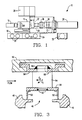
- Fig. 1 is a layout of a typical electric-generating plant which utilizes a combustion turbine;
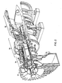
- Fig. 2 is an isometric view, partly cutaway, of the combustion turbine shown in Fig. 1;
- Fig. 3 illustrates the forces which impact upon an inner-shrouded vane manufactured in accordance with one prior art method;
- Fig. 4 shows another inner-shrouded vane manufactured in accordance with a second prior art method;
- Fig. 5 is an isometric view of an inner-shrouded vane according to the present invention;
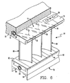
- Fig. 6 depicts the inner-shrouded vane shown in Fig. 5 as assembled in accordance with a preferred embodiment of the present invention; and
- Fig. 7 is a top view of the assembly shown in Fig. 6 illustrating the predetermined angle at which the inner-shrouded vanes according to the present invention are disposed.
- Referring now to the drawings, wherein like characters designate like or corresponding parts throughout each of the several views, there is shown in Fig. 1 the layout of a typical electric-generating
plant 10 utilizing a well known combustion turbine 12 (such as the model W-501D single shaft, heavy duty combustion turbine that is manufactured by the Combustion Turbine Systems Division of Westinghouse Electric Corporation). As is conventional, theplant 10 includes agenerator 14 driven by theturbine 12, astarter package 16, anelectrical package 18 having aglycol cooler 20, a mechanical package 22 having anoil cooler 24, and anair cooler 26, each of which support theoperating turbine 12. Conventional means 28 for silencing flow noise associated with theoperating turbine 12 are provided for at the inlet duct and at the exhaust stack of theplant 10, while conventional terminal means 30 are provided at thegenerator 14 for conducting the generated electricity therefrom. - As is shown in greater detail in Fig. 2, the
turbine 12 is comprised generally of aninlet portion 32, acompressor portion 34, acombustor portion 36, and anexhaust portion 38. Air entering theturbine 12 at itsinlet portion 32 is compressed adiabatically in thecompressor portion 34, and is mixed with a fuel and heated at a constant pressure in thecombustor portion 36. The heated fuel/air gases are thereafter discharged from thecombustor portion 36 through theexhaust portion 38 with a resulting adiabatic expansion of the gases completing the basic combustion turbine cycle. Such thermodynamic cycle is alternatively referred to as the Brayton, or Joule, cycle. - In order to ensure that a desirably highly efficient, high pressure ratio is maintained in the
turbine 12, thecompressor portion 34, like most compressor portions of conventional combustion turbines, is of an axial flow configuration having arotor 40. Therotor 40 includes a plurality of rotatingblades 42, axially disposed along ashaft 44, and a plurality ofdiscs 46. Each adjacent pair of the plurality of rotatingblades 42 is interspersed by one of a plurality of inner-shroudedstationary vanes 48, mounted to theturbine casing 50 as explained in greater detail herein below, thereby providing a diaphragm assembly in conjunction with thediscs 46 with steppedlabyrinth interstage seals 52. - Due to conventionally used methods of manufacturing inner-shrouded
vanes 48, there exists a significant problem of fatigue cracking. For example (and referring now to Figs. 3 and 4), in either of the methods that have been used by the manufacturers of most compressor diaphragm assemblies, a welding process is used to join anairfoil portion 54 of the inner-shroudedvane 48 to its respective inner 56 andouter shrouds 58. Such processes, as is well known, result in a heat-affectedzone 60 at eachweld joint 62. - As defined by the Metals Handbook (9th ed.), Volume 6: "Welding, Brazing, and Soldering", American Society for Metals, Metals Park, Ohio, a "heat-affected zone" is that portion of the base metal which has not been melted, but whose mechanical properties or microstructure have been altered by the heat of welding, brazing, soldering, or cutting. In stainless steels alloys of the type utilized for the
airfoils 54,inner shrouds 56 andouter shrouds 58, crack initiation due to fatigue more often than not occurs at such heat-affectedzones 60. - As noted above, however, problems associated with fatigue cracking are not resolved merely by eliminating those manufacturing processes that produce the heat-affected
zones 58. For example, Fig. 3 illustrates an inner-shroudedvane 48 that is manufactured by the rolled constant section approach, while Fig. 4 illustrates an inner-shroudedvane 48 that is manufactured by the forged variable thickness-to-chord ratio approach. - Forces that typically act upon the
inner shroud 56 and itsseal 52 of conventional compressor diaphragm assemblies such as those shown in Figs. 3 and 4 are primarily due to seal pressure drop FS. Those forces, as well as aerodynamic forces acting normally FA and tangentially FT uponairfoil portion 54, each contribute to the generation of other forces and moments that are transferred to theouter shroud 56, and subsequently to thecasing 50 of thecombustion turbine 12 via theweld joints 62 which attach thevane airfoil 54 to theouter shroud 58. - Fatigue cracking, nevertheless, would still not be eliminated through use of a hypothetical airfoil having an integrally formed inner and outer shroud, thereby doing away with the heat-affected
zones 60. Under the influence of the static forces and moments described above, the outer shroud segment of this hypothetical vane airfoil would not be stably engaged with the casing of the combustion turbine until such time that a restraining moment could be generated by contact of the extremities of the outer shroud segment with the walls of the slot formed in the casing to receive the segment. The outer shroud segment would, thus, rotate within the clearance gap (provided in the casing slot to account for thermal expansion). As a result, use of the hypothetical vane airfoil in a combustion turbine would lead to a great deal of stress in the vicinity of the outer shroud segment and excessive translational and rotational displacement, each of which would be further exacerbated under dynamic stimuli. - It has been found that a
compressor diaphragm assembly 64, as shown in Figs. 5-7, will substantially eliminate the fatigue cracking problems described herein above. As shown in Fig. 5, thecompressor diaphragm assembly 64 includes a plurality ofvane airfoils 66, each of which is formed with an integralinner shroud 68, a segmentedseal carrier 70 suspended from theinner shroud 68, and a segmentedouter ring 72 for supporting the plurality ofvane airfoils 66, at a predetermined angle AS (Fig. 7) with respect to the longitudinal axis of theturbine 12, through engagement with aslot 74 formed circumferentially in thecasing 50 of theturbine 12. Each of theouter ring segments 76 has one ormore grooves 78 formed to engagably receive a respective one of thevane airfoils 66 at itsouter portion 80. Eachseal carrier segment 82 includes a pair of disc-engaging seals 84, and is formed to be engaged with theinner shrouds 68 of one ormore vane airfoils 66. - In accordance with one important aspect of the present invention, heat-affected zones are eliminated since the plurality of
vane airfoils 66, with their integrally formedinner shrouds 68, are joined to their respective outer ring andseal carrier segments vane airfoils 66 and the casing slot 74 (due either to static or dynamic stimuli) since theouter portion 80 of eachvane airfoil 66 is formed to engage itsrespective groove 78 parallel to the predetermined angle AS. - The predetermined angle AS, generally referred to as the "stagger angle", is the angle at which each of the
vane airfoils 66 are aligned relative to the longitudinal axis of theturbine 12. That is, and referring for the moment to Fig. 7 in conjunction with Fig. 5, theouter portion 80 of thevane airfoil 66 is rotated until it is parallel to the stagger angle, and thus, perpen dicular to the forces generated by FT. Theouter portion 80 thereby engages aslot 78 formed in anouter ring segment 76 at this stagger angle AS, causing the distribution of normal forces acting on theouter portion 80 to be more uniform. This, in combination with 0.001-inch clearances typical of rotor blades, provides a stable restraint system with minimum displacements and rotations of thevane airfoils 66. - Referring again to Fig. 6, it can be seen that a plurality of the
vane airfoils 66 are assembled into theouter ring segments 76 by inserting their respectiveouter portions 80 into thegrooves 78 formed in theouter ring segments 76. As such, thevane airfoils 66 and especially theirouter portions 80 are aligned optimally parallel to the stagger angle AS. While each of theouter portions 80 are shown having a generally triangular shaped cross-section, it should be noted at this juncture that any such cross-section may be utilized in accordance with the present invention as long as it is complementary to the cross-section of thegrooves 78. - The respective
outer ring segments 76 may be joined to form theouter ring 72 with tie bars 86 and indexing screws 88. Alternatively, theouter ring segments 76 may remain unjoined as long as the arc that is defined by the unjoinedouter ring segments 76 is equal to the arc defined by thesegmented seal carrier 70. In either case, theouter ring segments 76 are formed with a generally T-shaped cross-section for engagement with theslot 74 formed in thecasing 50 of theturbine 12, held in place by conventional retaining screws 90. - In order to facilitate assembly and disassembly of the compressor diaphragm according to the present invention, and to minimize the cost of producing such an assembly, spacers 92 of varying sizes are provided to properly space the
vane airfoils 66 one from the other. As in the case of the tie bars 86 and theouter portions 80 of the vane airfoils 66, theinner portions 68 of eachvane airfoil 66 as well as anyspacers 92 between thevane airfoils 66 are locked in place as necessary with conventional retaining screws 90 or with indexing screws 88. - As explained herein above, the compressor diaphragm assembly according to the present invention thus eliminates problems of fatigue cracking caused by heat-affected zones. This also substantially reduces stress concentrations that typically build up at the inner and outer shrouds. Integrally formed vane airfoils minimizes costs associated with manufacture of such airfoils, while maximizing the quality of their production since long-established procedures that have been utilized for rotor blade manufacture (e.g., castings, forgings, contour millings, etc.) can be applied. As is readily evident, replacement of a single damaged
vane airfoil 66 is easily accomplished, and the multiplicity of interfaces between the vane airfoils 66,segmented seal carrier 70,outer ring 72, and slot 74 provide for increased mechanical damping which will minimize dynamic response. - Obviously, many modifications and variations are possible in light of the foregoing. It is, therefore, to be understood that within the scope of the appended claims, the invention may be practiced otherwise than as specifically described herein.
Claims (6)
Applications Claiming Priority (2)
| Application Number | Priority Date | Filing Date | Title |
|---|---|---|---|
| US226705 | 1981-01-21 | ||
| US07/226,705 US4889470A (en) | 1988-08-01 | 1988-08-01 | Compressor diaphragm assembly |
Publications (2)
| Publication Number | Publication Date |
|---|---|
| EP0353498A2 true EP0353498A2 (en) | 1990-02-07 |
| EP0353498A3 EP0353498A3 (en) | 1990-12-27 |
Family
ID=22850064
Family Applications (1)
| Application Number | Title | Priority Date | Filing Date |
|---|---|---|---|
| EP19890112680 Withdrawn EP0353498A3 (en) | 1988-08-01 | 1989-07-11 | Compressor diaphragm assembly |
Country Status (9)
| Country | Link |
|---|---|
| US (1) | US4889470A (en) |
| EP (1) | EP0353498A3 (en) |
| JP (1) | JP2835381B2 (en) |
| KR (1) | KR970001123B1 (en) |
| CN (1) | CN1040078A (en) |
| AR (1) | AR240714A1 (en) |
| AU (1) | AU613214B2 (en) |
| CA (1) | CA1333472C (en) |
| MX (1) | MX164476B (en) |
Cited By (10)
| Publication number | Priority date | Publication date | Assignee | Title |
|---|---|---|---|---|
| EP1801357A1 (en) | 2005-12-22 | 2007-06-27 | Techspace aero | Bladed nozzle of a turbomachine, turbomachine comprising this nozzle and turbomachine vane |
| EP1852575A1 (en) * | 2006-01-27 | 2007-11-07 | Mitsubishi Heavy Industries, Ltd. | Stationary blade ring of axial compressor |
| WO2009048455A1 (en) * | 2007-01-17 | 2009-04-16 | Siemens Energy, Inc. | A gas turbine engine |
| WO2010128900A1 (en) | 2009-05-08 | 2010-11-11 | Volvo Aero Corporation | Supporting structure for a gas turbine engine |
| FR2980249A1 (en) * | 2011-09-20 | 2013-03-22 | Snecma | Structural intermediate casing for e.g. turbojet of aircraft, has set of non-structural rectifiers arranged interdependent of hub, where non-structural rectifiers are fixed in removable manner by its ends internally at internal ring |
| EP1967697A3 (en) * | 2007-03-07 | 2015-05-06 | General Electric Company | Turbine nozzle segment and repair method |
| EP2900932A4 (en) * | 2012-09-28 | 2016-07-27 | United Technologies Corp | THERMAL SHIRT LOCKING SEGMENT |
| FR3048719A1 (en) * | 2016-03-14 | 2017-09-15 | Snecma | FLOW RECTIFIER FOR TURBOMACHINE WITH INTEGRATED AND REPORTED PLATFORMS |
| CN109882255A (en) * | 2019-03-01 | 2019-06-14 | 西安航天动力研究所 | Turbine stator top sealing limit structure with blade profile groove |
| WO2019147219A1 (en) * | 2018-01-23 | 2019-08-01 | Siemens Aktiengesellschaft | Slide on shroud cover segments for gas turbine compressor stator vanes |
Families Citing this family (32)
| Publication number | Priority date | Publication date | Assignee | Title |
|---|---|---|---|---|
| US5022818A (en) * | 1989-02-21 | 1991-06-11 | Westinghouse Electric Corp. | Compressor diaphragm assembly |
| US5236614A (en) | 1990-09-25 | 1993-08-17 | Colgate-Palmolive Company | Stable microemulsion disinfecting detergent composition |
| US5197856A (en) * | 1991-06-24 | 1993-03-30 | General Electric Company | Compressor stator |
| US5332360A (en) * | 1993-09-08 | 1994-07-26 | General Electric Company | Stator vane having reinforced braze joint |
| US6632070B1 (en) * | 1999-03-24 | 2003-10-14 | Siemens Aktiengesellschaft | Guide blade and guide blade ring for a turbomachine, and also component for bounding a flow duct |
| JP2002180803A (en) * | 2000-12-13 | 2002-06-26 | Ishikawajima Harima Heavy Ind Co Ltd | Support device |
| JP4040922B2 (en) * | 2001-07-19 | 2008-01-30 | 株式会社東芝 | Assembly type nozzle diaphragm and its assembly method |
| FR2831615B1 (en) * | 2001-10-31 | 2004-01-02 | Snecma Moteurs | SECTORIZED FIXED RECTIFIER FOR A TURBOMACHINE COMPRESSOR |
| US6644924B1 (en) * | 2002-05-31 | 2003-11-11 | General Electric Company | Covers for turbine buckets and methods of assembly |
| WO2003104616A1 (en) * | 2002-06-07 | 2003-12-18 | 三菱重工業株式会社 | Turbine bucket assembly and its assembling method |
| JP4590955B2 (en) * | 2004-07-08 | 2010-12-01 | 株式会社Ihi | Stator segment, stator, and stator blade |
| US7427187B2 (en) * | 2006-01-13 | 2008-09-23 | General Electric Company | Welded nozzle assembly for a steam turbine and methods of assembly |
| US8702385B2 (en) * | 2006-01-13 | 2014-04-22 | General Electric Company | Welded nozzle assembly for a steam turbine and assembly fixtures |
| FR2899637B1 (en) * | 2006-04-06 | 2010-10-08 | Snecma | STATOR VANE WITH VARIABLE SETTING OF TURBOMACHINE |
| US20080050222A1 (en) * | 2006-08-23 | 2008-02-28 | General Electric Company | Singlet welded nozzle hybrid design for a turbine |
| US8894370B2 (en) * | 2008-04-04 | 2014-11-25 | General Electric Company | Turbine blade retention system and method |
| US8887390B2 (en) | 2008-08-15 | 2014-11-18 | Dresser-Rand Company | Method for correcting downstream deflection in gas turbine nozzles |
| US8511982B2 (en) * | 2008-11-24 | 2013-08-20 | Alstom Technology Ltd. | Compressor vane diaphragm |
| US8047778B2 (en) * | 2009-01-06 | 2011-11-01 | General Electric Company | Method and apparatus for insuring proper installation of stators in a compressor case |
| US8118550B2 (en) * | 2009-03-11 | 2012-02-21 | General Electric Company | Turbine singlet nozzle assembly with radial stop and narrow groove |
| US8123474B2 (en) * | 2009-05-12 | 2012-02-28 | Dresser-Rand Company | Repair of industrial gas turbine nozzle diaphragm packing |
| US8632300B2 (en) | 2010-07-22 | 2014-01-21 | Siemens Energy, Inc. | Energy absorbing apparatus in a gas turbine engine |
| FR2984428B1 (en) * | 2011-12-19 | 2018-12-07 | Safran Aircraft Engines | COMPRESSOR RECTIFIER FOR TURBOMACHINE. |
| EP2801702B1 (en) * | 2013-05-10 | 2020-05-06 | Safran Aero Boosters SA | Inner shroud of turbomachine with abradable seal |
| DE112013007175B4 (en) | 2013-06-20 | 2022-06-30 | Mitsubishi Power, Ltd. | Gas guiding device and system having it |
| CN103343704B (en) * | 2013-07-23 | 2015-03-25 | 上海电气电站设备有限公司 | Open-type integrated nozzle block structure and machining method |
| JP6185783B2 (en) * | 2013-07-29 | 2017-08-23 | 三菱日立パワーシステムズ株式会社 | Axial flow compressor, gas turbine equipped with axial flow compressor, and method for remodeling axial flow compressor |
| CN106471218A (en) * | 2014-03-27 | 2017-03-01 | 西门子股份公司 | Stator blade support system in a gas turbine engine |
| US10641282B2 (en) * | 2016-12-28 | 2020-05-05 | Nidec Corporation | Fan device and vacuum cleaner including the same |
| US10900364B2 (en) * | 2017-07-12 | 2021-01-26 | Raytheon Technologies Corporation | Gas turbine engine stator vane support |
| PL431184A1 (en) | 2019-09-17 | 2021-03-22 | General Electric Company Polska Spółka Z Ograniczoną Odpowiedzialnością | Turboshaft engine set |
| CN111561394B (en) * | 2020-05-25 | 2021-07-09 | 中国航发沈阳发动机研究所 | Structure of engine air inlet casing and assembling method thereof |
Family Cites Families (14)
| Publication number | Priority date | Publication date | Assignee | Title |
|---|---|---|---|---|
| DE757505C (en) * | 1940-06-13 | 1954-03-15 | Messerschmitt Boelkow Blohm | Axially loaded guide device for centrifugal machines, especially turbines with high heat loads |
| GB660383A (en) * | 1949-02-23 | 1951-11-07 | Winnett Boyd | Blade mounting for axial-flow compressors and the like |
| BE532194A (en) * | 1953-10-23 | |||
| US2834537A (en) * | 1954-01-18 | 1958-05-13 | Ryan Aeronautical Co | Compressor stator structure |
| GB780137A (en) * | 1955-07-07 | 1957-07-31 | Gen Motors Corp | Improvements relating to axial-flow compressors |
| GB853314A (en) * | 1956-10-05 | 1960-11-02 | Power Jets Res & Dev Ltd | Improvements in or relating to axial flow turbo-machines such as turbines or compressors |
| US3339833A (en) * | 1963-12-04 | 1967-09-05 | Rolls Royce | Axial fluid flow machine such as a compressor or turbine |
| GB1116580A (en) * | 1965-11-17 | 1968-06-06 | Bristol Siddeley Engines Ltd | Stator blade assemblies for axial-flow turbine engines |
| US3849023A (en) * | 1973-06-28 | 1974-11-19 | Gen Electric | Stator assembly |
| SU496377A1 (en) * | 1974-03-21 | 1975-12-25 | Предприятие П/Я Р-6837 | Axial compressor stator |
| FR2535795B1 (en) * | 1982-11-08 | 1987-04-10 | Snecma | DEVICE FOR SUSPENSION OF STATOR BLADES OF AXIAL COMPRESSOR FOR ACTIVE CONTROL OF GAMES BETWEEN ROTOR AND STATOR |
| DE3341871A1 (en) * | 1983-11-19 | 1985-05-30 | Brown, Boveri & Cie Ag, 6800 Mannheim | Axial compressor |
| US4741667A (en) * | 1986-05-28 | 1988-05-03 | United Technologies Corporation | Stator vane |
| US4767267A (en) * | 1986-12-03 | 1988-08-30 | General Electric Company | Seal assembly |
-
1988
- 1988-08-01 US US07/226,705 patent/US4889470A/en not_active Expired - Lifetime
-
1989
- 1989-07-11 EP EP19890112680 patent/EP0353498A3/en not_active Withdrawn
- 1989-07-13 AU AU38076/89A patent/AU613214B2/en not_active Ceased
- 1989-07-27 JP JP1195405A patent/JP2835381B2/en not_active Expired - Lifetime
- 1989-07-27 AR AR31452189A patent/AR240714A1/en active
- 1989-07-31 CN CN89105482A patent/CN1040078A/en active Pending
- 1989-07-31 MX MX16989A patent/MX164476B/en unknown
- 1989-08-01 KR KR1019890010958A patent/KR970001123B1/en not_active Expired - Lifetime
- 1989-08-01 CA CA000607228A patent/CA1333472C/en not_active Expired - Fee Related
Cited By (18)
| Publication number | Priority date | Publication date | Assignee | Title |
|---|---|---|---|---|
| US7722321B2 (en) | 2005-12-22 | 2010-05-25 | Techspace Aero | Turbo-engine stator blading, turbo-engine comprising the blading and turbo-engine blade |
| EP1801357A1 (en) | 2005-12-22 | 2007-06-27 | Techspace aero | Bladed nozzle of a turbomachine, turbomachine comprising this nozzle and turbomachine vane |
| EP1852575A1 (en) * | 2006-01-27 | 2007-11-07 | Mitsubishi Heavy Industries, Ltd. | Stationary blade ring of axial compressor |
| US8206094B2 (en) | 2006-01-27 | 2012-06-26 | Mitsubishi Heavy Industries, Ltd. | Stationary blade ring of axial compressor |
| WO2009048455A1 (en) * | 2007-01-17 | 2009-04-16 | Siemens Energy, Inc. | A gas turbine engine |
| US8128354B2 (en) | 2007-01-17 | 2012-03-06 | Siemens Energy, Inc. | Gas turbine engine |
| EP1967697A3 (en) * | 2007-03-07 | 2015-05-06 | General Electric Company | Turbine nozzle segment and repair method |
| WO2010128900A1 (en) | 2009-05-08 | 2010-11-11 | Volvo Aero Corporation | Supporting structure for a gas turbine engine |
| EP2427635A4 (en) * | 2009-05-08 | 2016-12-21 | Gkn Aerospace Sweden Ab | SUPPORT STRUCTURE FOR GAS TURBINE |
| FR2980249A1 (en) * | 2011-09-20 | 2013-03-22 | Snecma | Structural intermediate casing for e.g. turbojet of aircraft, has set of non-structural rectifiers arranged interdependent of hub, where non-structural rectifiers are fixed in removable manner by its ends internally at internal ring |
| EP2900932A4 (en) * | 2012-09-28 | 2016-07-27 | United Technologies Corp | THERMAL SHIRT LOCKING SEGMENT |
| US10287919B2 (en) | 2012-09-28 | 2019-05-14 | United Technologies Corporation | Liner lock segment |
| FR3048719A1 (en) * | 2016-03-14 | 2017-09-15 | Snecma | FLOW RECTIFIER FOR TURBOMACHINE WITH INTEGRATED AND REPORTED PLATFORMS |
| WO2017158266A1 (en) * | 2016-03-14 | 2017-09-21 | Safran Aircraft Engines | Flow stator for turbomachine with integrated and attached platforms |
| GB2563796A (en) * | 2016-03-14 | 2018-12-26 | Safran Aircraft Engines | Flow stator for turbomachine with integrated and attached platforms |
| GB2563796B (en) * | 2016-03-14 | 2021-08-11 | Safran Aircraft Engines | Flow stator for turbomachine with integrated and attached platforms |
| WO2019147219A1 (en) * | 2018-01-23 | 2019-08-01 | Siemens Aktiengesellschaft | Slide on shroud cover segments for gas turbine compressor stator vanes |
| CN109882255A (en) * | 2019-03-01 | 2019-06-14 | 西安航天动力研究所 | Turbine stator top sealing limit structure with blade profile groove |
Also Published As
| Publication number | Publication date |
|---|---|
| KR970001123B1 (en) | 1997-01-28 |
| KR900003520A (en) | 1990-03-26 |
| MX164476B (en) | 1992-08-19 |
| EP0353498A3 (en) | 1990-12-27 |
| JPH0270929A (en) | 1990-03-09 |
| CA1333472C (en) | 1994-12-13 |
| AU613214B2 (en) | 1991-07-25 |
| AU3807689A (en) | 1990-02-01 |
| CN1040078A (en) | 1990-02-28 |
| AR240714A1 (en) | 1990-09-28 |
| JP2835381B2 (en) | 1998-12-14 |
| US4889470A (en) | 1989-12-26 |
Similar Documents
| Publication | Publication Date | Title |
|---|---|---|
| CA1333472C (en) | Compressor diaphragm assembly | |
| US5022818A (en) | Compressor diaphragm assembly | |
| JP4569950B2 (en) | Method and apparatus for controlling the tip clearance of a gas turbine engine rotor | |
| EP0735239B1 (en) | Gas turbine system and method of manufacturing | |
| EP1270875B1 (en) | Turbine leaf seal mounting with headless pins | |
| EP1657405B1 (en) | Stator vane assembly for a gas turbine | |
| EP2204534B1 (en) | Turbine airfoil clocking | |
| WO2009108084A1 (en) | A gas turbine component and a method for producing a gas turbine component | |
| WO2014133483A1 (en) | Segmented clearance control ring | |
| GB2458770A (en) | Supporting gas turbine stator components | |
| US5156525A (en) | Turbine assembly | |
| KR101965493B1 (en) | Method of disassembling and assembling a gas turbine and a gas turbine assembled thereby | |
| EP3409898B1 (en) | Belly band seals and method | |
| KR20190001906A (en) | Method of disassembling and assembling a gas turbine and a gas turbine assembled thereby | |
| EP3421171B1 (en) | Turbine wheels, turbine engines including the same, and methods of fabricating turbine wheels with improved bond line geometry | |
| US11015483B2 (en) | High pressure compressor flow path flanges with leak resistant plates for improved compressor efficiency and cyclic life | |
| Rocha et al. | Evolution of the Solar Turbines Titan 130 industrial gas turbine | |
| Sugimoto et al. | Development of a 20MW-class high-efficiency gas turbine L20A | |
| KR20190001905A (en) | Method of disassembling and assembling a gas turbine and a gas turbine assembled thereby | |
| Tanimura et al. | Development of an 8MW-class high-efficiency gas turbine, M7A-03 | |
| SAUNDERS | Advanced component technologies for energy-efficient turbofan engines | |
| WO2020149854A1 (en) | Pre-swirler with pre-swirler plug for gas turbine engine | |
| Heilmann | Review of the development of small-and medium-capacity gas turbines at the Motoren-und Turbinen Union |
Legal Events
| Date | Code | Title | Description |
|---|---|---|---|
| PUAI | Public reference made under article 153(3) epc to a published international application that has entered the european phase |
Free format text: ORIGINAL CODE: 0009012 |
|
| AK | Designated contracting states |
Kind code of ref document: A2 Designated state(s): BE CH DE FR GB IT LI NL SE |
|
| 17P | Request for examination filed |
Effective date: 19900612 |
|
| PUAL | Search report despatched |
Free format text: ORIGINAL CODE: 0009013 |
|
| RHK1 | Main classification (correction) |
Ipc: F01D 9/04 |
|
| AK | Designated contracting states |
Kind code of ref document: A3 Designated state(s): BE CH DE FR GB IT LI NL SE |
|
| 17Q | First examination report despatched |
Effective date: 19920212 |
|
| STAA | Information on the status of an ep patent application or granted ep patent |
Free format text: STATUS: THE APPLICATION IS DEEMED TO BE WITHDRAWN |
|
| 18D | Application deemed to be withdrawn |
Effective date: 19920804 |