EP0353289B1 - System and method for hierarchal image encoding and decoding - Google Patents
System and method for hierarchal image encoding and decoding Download PDFInfo
- Publication number
- EP0353289B1 EP0353289B1 EP89902431A EP89902431A EP0353289B1 EP 0353289 B1 EP0353289 B1 EP 0353289B1 EP 89902431 A EP89902431 A EP 89902431A EP 89902431 A EP89902431 A EP 89902431A EP 0353289 B1 EP0353289 B1 EP 0353289B1
- Authority
- EP
- European Patent Office
- Prior art keywords
- values
- coded
- primary array
- sequence
- coded values
- Prior art date
- Legal status (The legal status is an assumption and is not a legal conclusion. Google has not performed a legal analysis and makes no representation as to the accuracy of the status listed.)
- Expired - Lifetime
Links
- 238000000034 method Methods 0.000 title claims abstract description 57
- 125000004122 cyclic group Chemical group 0.000 claims abstract description 50
- 230000005540 biological transmission Effects 0.000 abstract description 14
- 238000003491 array Methods 0.000 abstract description 5
- 238000010586 diagram Methods 0.000 description 80
- 238000013144 data compression Methods 0.000 description 11
- 230000006870 function Effects 0.000 description 9
- 238000012360 testing method Methods 0.000 description 7
- 238000004891 communication Methods 0.000 description 6
- 230000008569 process Effects 0.000 description 6
- 238000013461 design Methods 0.000 description 4
- 101000706563 Homo sapiens SUN domain-containing protein 3 Proteins 0.000 description 2
- 102100031129 SUN domain-containing protein 3 Human genes 0.000 description 2
- 238000006243 chemical reaction Methods 0.000 description 2
- 230000005670 electromagnetic radiation Effects 0.000 description 2
- 230000036039 immunity Effects 0.000 description 2
- 238000012545 processing Methods 0.000 description 2
- 230000002250 progressing effect Effects 0.000 description 2
- 238000010187 selection method Methods 0.000 description 2
- 230000003595 spectral effect Effects 0.000 description 2
- 101000706551 Homo sapiens SUN domain-containing protein 2 Proteins 0.000 description 1
- 102100031131 SUN domain-containing protein 2 Human genes 0.000 description 1
- 238000010276 construction Methods 0.000 description 1
- 230000007423 decrease Effects 0.000 description 1
- 230000003467 diminishing effect Effects 0.000 description 1
- 238000004519 manufacturing process Methods 0.000 description 1
- 238000012986 modification Methods 0.000 description 1
- 230000004048 modification Effects 0.000 description 1
- 230000003287 optical effect Effects 0.000 description 1
- 239000013307 optical fiber Substances 0.000 description 1
- 230000000750 progressive effect Effects 0.000 description 1
- 238000013139 quantization Methods 0.000 description 1
- 230000009467 reduction Effects 0.000 description 1
- 230000009466 transformation Effects 0.000 description 1
- 238000001429 visible spectrum Methods 0.000 description 1
Images



Classifications
-
- A—HUMAN NECESSITIES
- A61—MEDICAL OR VETERINARY SCIENCE; HYGIENE
- A61F—FILTERS IMPLANTABLE INTO BLOOD VESSELS; PROSTHESES; DEVICES PROVIDING PATENCY TO, OR PREVENTING COLLAPSING OF, TUBULAR STRUCTURES OF THE BODY, e.g. STENTS; ORTHOPAEDIC, NURSING OR CONTRACEPTIVE DEVICES; FOMENTATION; TREATMENT OR PROTECTION OF EYES OR EARS; BANDAGES, DRESSINGS OR ABSORBENT PADS; FIRST-AID KITS
- A61F6/00—Contraceptive devices; Pessaries; Applicators therefor
- A61F6/06—Contraceptive devices; Pessaries; Applicators therefor for use by females
-
- H—ELECTRICITY
- H04—ELECTRIC COMMUNICATION TECHNIQUE
- H04N—PICTORIAL COMMUNICATION, e.g. TELEVISION
- H04N19/00—Methods or arrangements for coding, decoding, compressing or decompressing digital video signals
- H04N19/90—Methods or arrangements for coding, decoding, compressing or decompressing digital video signals using coding techniques not provided for in groups H04N19/10-H04N19/85, e.g. fractals
Definitions
- This invention relates to a system and a method for the hierarchal encoding and decoding of an image.
- Hierarchal encoding of images is known and has been proposed as an alternative to conventional line-by-line image encoding techniques for the transmission of images over communication channels of restricted bandwidth.
- data corresponding to gross approximations of an image are transmitted first, followed by data corresponding to more refined approximations until the final image is transmitted. Therefore, the quality of the reconstructed image at the receiver is progressively improved as more image data is received.
- One of the principal advantages of progressive image transmission using hierarchal encoding is the early recognition of the received image before transmission of the final image is completed. This is so because in many instances an early coarse approximation of an image is sufficient to permit identification of what is contained in the final image.
- Hierarchal encoding of images is typically implemented by processing the information in an image to generate an explicit pyramidal data structure.
- a data structure contains multiple levels, each representing a successive approximation of the final image with the lowest level at the base of the pyramid representing the final image.
- Transmission of the pyramidal data structure begins at the highest level, i.e., at the vertex of the pyramid, followed by the transmission of successive lower levels.
- the present invention in one aspect is a system for the hierarchical encoding of an image
- memory means having a multiplicity of addressable storage locations for storing data
- first encoding means responsive to the first coded values for generating in a number of passes a sequence of second coded values, stored in respective locations in the memory means and hierarchically arranged to represent the progressively improved approximation of the image, said first encoding means selecting a predetermined number of distinct pairs of first coded values and determining the respective modulo 2 b difference of these selected pairs during each pass where b is the number of bits used to represent a first coded value, such that the sequence of second coded values comprises MxN second coded values having X selected first code
- the sequence of second coded values has as its first code a selected first code value followed by MxN-1 respective cyclic differences of MxN-1 selected distinct pairs of first code values.
- the M rows of the primary array include a first row
- the N columns of the primary array include a first column
- the selected first coded value is the value in the first row and the first column of the primary array.
- the means for selecting pairs of first coded values makes alternating horizontal and vertical passes.
- system further comprises image scanning means for providing the first coded values representative of the intensities of the picture elements of the image.
- the image scanning means includes means for decomposing the image into a pixel array having M rows and N columns, and means for deriving binary coded values corresponding to respective image intensities of the pixels.
- Another aspect of the present invention is a system for hierarchical decoding of an image
- means for receiving a sequence of output encoded values representative of an image comprising means for receiving a sequence of output encoded values representative of an image; memory means having a multiplicity of addressable storage locations for storing data; and first decoding means responsive to the sequence of output encoded values for providing a corresponding sequence of first coded values stored in respective locations of the memory means; characterized by second decoding means responsive to the sequence of first coded values for deriving a primary array of second coded values stored in respective locations in the memory means, the primary array having M rows and N columns, where M and N are predetermined integers, the sequence of first coded values including X values belonging to specified positions of the primary array followed by a total of Y respective modulo 2 b cyclic differences - where b is the number of bits used to represent a second coded value - of a total of Y distinct pairs of values belonging to specified positions of the primary array, where X is an integer less than MxN and
- the sequence of first coded values begins with one value belonging to a specified position in the primary array and the following MxN-1 respective cyclic differences of MxN-1 distinct pairs of values belonging to specified positions in the primary array
- the means for deriving the MxN-1 distinct pairs of second coded values makes alternating horizontal and vertical passes.
- system further comprises display means responsive to the display signals provided by the third decoding means for presenting the image represented by the display signals.
- Still further aspects of the present invention are a method for the hierarchal encoding of an image and a method for the hierarchal decoding an image as carried out, for example, by the foregoing system for the hierarchal encoding and decoding of an image, respectively.
- the coder-decoder system 100 includes an encoder section 101 and a decoder section 102.
- the encoder section 101 has a conventional image scanner 1 for performing a line-by-line scan of an image (not shown) and providing analog signals representative of the scanned image.
- the image scanner 1 may be one which provides either grey-scale or colour operation. In the case of grey-scale operation, the analog scan signals provided by the image scanner represent the light intensity values along each scan line. In the case of colour operation, the analog scan signals provided by the image scanner represent the light intensity values along each scan line as obtained through red, green, and blue spectral filters, respectively.
- the image scanner provides three times the intensity value information provided in grey-scale operation.
- colour images are encoded and decoded in the same manner as grey-scale images, except that the intensity values obtained through each spectral filter are encoded and decoded separately.
- the intensity values provided by the image scanner may be for electromagnetic radiation having wavelengths outside of the visible spectrum.
- the principles of the present invention are equally applicable to images obtained with non-electromagnetic radiation such as sonar images.
- the image scanner scans the image horizontally from left to right, beginning at the top of the image and progressing on a line-by-line basis to the bottom of the image.
- the number of scanning lines used depends on the desired vertical resolution, a typical number being 256 lines.
- the encoder section 101 also includes a digitizer 2, which divides each scan line into a finite number of segments, called pixels. Furthermore, the digitizer 2 quantizes the light intensity value in each segment to a nearest preset value, i.e., a quantization level, and represents the quantized intensity value as a binary code.
- the conversion of the analog intensity value signals provided by the image scanner 1 into binary codes is called pulse code modulation (PCM), and each binary code represents the light intensity value of a particular pixel of the image.
- PCM pulse code modulation
- the number of pixels per scan line depends on the desired horizontal resolution, a typical number being 256 pixels per line.
- the number of bits used for the binary code representing the light intensity value of each pixel depends on the desired intensity value resolution. The higher the intensity value resolution, the greater is the number of bits required to represent the light intensity value of each pixel.
- the output of the digitizer 2 is commonly referred to as the digitized original image or pixel intensity value array.
- the respective functions of the image scanner 1 and the digitizer 2 may be combined in a single device, called a digital scanner.
- the digitized original image provided by the digitizer 2 is stored in a Random-Access Memory (RAM) 3 of the encoder section 101 as a primary array of binary coded intensity values, the primary array having M rows and N columns, where M is equal to the number of scan lines used and N is equal to the number of pixels per scan line.
- the digitizer 2 contains appropriate circuitry for addressing RAM 3 for writing the digitized image in respective locations thereof.
- the encoder section 101 further includes a conventional digital processor 4, which executes an encoding program routine for converting the digitized image stored in the RAM 3 into a sequence of hierarchal codes representing the digitized original image. The sequence of hierarchal codes are also stored in respective locations in the RAM 3.
- the encoder section 101 of the image encoder-decoder system 100 has an output encoder 5 for converting the sequence of hierarchal codes stored in the RAM 3 into a corresponding sequence of appropriate output codes providing a lossless data compression of the sequence of hierarchal codes prior to transmission.
- the output codes, which are stored in the RAM 3, may be in the form of a known variable length code, such as the Huffman code.
- the encoder section 101 has a transmitter 6 for providing an appropriate carrier signal suitable for transmission over a communications channel 12.
- the transmitter 6 modulates the carrier signal with the sequence of output codes stored in the RAM 3.
- the communications channel 12 may be any suitable medium for conducting the modulated carrier signal from the transmitter 6, such as a telephone line, an optical fibre, a radio frequency or microwave wireless link.
- the decoder system 102 of the image code-decoder system 100 includes a receiver 7 coupled to a communications channel 13 for receiving a carrier signal modulated with an output encoded sequence of hierarchal codes representing an image being transmitted.
- the receiver 7 demodulates the carrier signal to extract the output encoded sequence of hierarchal codes and stores the same in respective locations in a RAM 10 forming part of the decoder section 102.
- An output decoder 8 is included in the decoder section 102 for converting the output encoded sequence of hierarchal codes in the RAM 10 into a corresponding sequence of hierarchal codes, which are also stored in respective locations in the RAM 10.
- the decoder section 102 further includes a conventional digital processor 9 which executes a decoding program routine for converting the sequence of hierarchal codes in the RAM 10 into a primary array of intensity values, the primary array of intensity values also being stored in respective locations in the RAM 10.
- the decoder section 102 further includes a display device 11 for converting the primary array of intensity values in the RAM 10 into appropriate display signals representing the image being transmitted. The image is then presented on a video screen of the display device 11.
- the encoder section 101 and decoder section 102 of the exemplary image coder-decoder system 100 are symmetrical in that each component, except for the RAMs 3 and 10, in one section performs the inverse function of its counterparts in the other section.
- the receiver 7 performs the inverse of the function of the transmitter 6, and the video display device 11 performs the inverse of the combined functions of the image scanner 1 and the digitizer 2.
- the image encoding and decoding techniques of the invention were tested using a Sun Microsystems, Inc. SUN3 workstation serving as the processor 4, RAM 3 and output encoder 5 of the encoder section 101 and also serving as the processor 9, RAM 10 and output decoder 8 of the decoder section 102.
- SUN3 workstation serving as the processor 4
- RAM 3 and output encoder 5 of the encoder section 101 and also serving as the processor 9, RAM 10 and output decoder 8 of the decoder section 102.
- the video monitor connected to a SUN2 workstation by the same manufacturer was used as the display device 11 of the decoder section 102.
- the functions of the output encoder 5 and the output decoder 8 were performed using respective program routines executed by the SUN3 workstation processor.
- An advantageous implementation of the image coder-decoder system 100 is to provide the digitizer 2, the processor 4, the RAM 3, the output encoder 5 and the transmitter 6 of the encoder section 101, and the processor 9, the RAM 10, the output decoder 8 and the receiver 7 of the decoder section 102 on a single integrated circuit chip.
- the RAM 3 and the RAM 10 may share the same RAM array, and a single appropriately programmed microprocessor may perform the functions of the processors 4 and 9, the output encoder 5 and the output decoder 8.
- the respective functions of the processors 4 and 9, the output encoder 5 and the output decoder 8 may all be implemented with hard-wired circuits in the integrated circuit chip.
- CCD's charged-coupled devices
- Fig. 2 there is shown a flow diagram representative of the encoding program routine executed by the processor 4 of the encoder section 101 in accordance with an exemplary embodiment of the invention.
- the program routine represented by the flow diagram 200 provides for converting the primary array of intensity values stored in the RAM 3 of the encoder section into a sequence of hierarchal codes, the number of codes being equal to the number of intensity values in the primary array.
- the first code in the sequence of hierarchal codes is the binary coded intensity value in the first row and first column of the primary array.
- the remaining codes in the sequence are the respective modulo K differences of MxN-1 distinct pairs of intensity values of the primary array.
- the distinct pairs of intensity values of the primary array are selected in a prescribed manner by making horizontal and vertical passes through the primary array.
- parameters p and q are initialized before the first pass. If the first pass is a horizontal pass, p is set to 1 and q is set to 0. If the first pass is a vertical pass, then q is set to 1 and p is set to 0.
- the position of an intensity value in the primary array is uniquely specified by a row index, i, indicating the row of the primary array in which the value is located, and a column index, j, indicating the column of the primary array in which the value is located.
- a row index, i indicating the row of the primary array in which the value is located
- a column index, j indicating the column of the primary array in which the value is located.
- a table useful for computing the modulo 4 cyclic difference between values V1 and V2 is shown in Fig. 3. In that table both V1 and V2 have integer values between 0 and 3 and can therefore be represented by a 2-bit binary code. Accordingly, a modulus of 4 is appropriate for taking the difference between V1 and V2.
- each modulo K difference between distinct pairs of primary array values computed in block 204 is stored sequentially in memory.
- the parameter p is incremented by 1 prior to each horizontal pass
- the parameter q is incremented by 1 prior to each vertical pass.
- the decision block 207 represents a test to determine whether the parameter p equals n and the parameter q equals m after each incrementation of p or q. If the test is negative, a new horizontal pass or vertical pass is made, as determined by preestablished procedure. If the test is affirmative, the value in the first row and first column of the primary array is stored as the first code in the sequence of hierarchal codes, in accordance with block 208 of the flow diagram 200, and the encoding of the primary array is completed.
- codmain5.c for a 256x256 pixel image
- the codmain5.c routine corresponds to the flow diagram 200 with the following exceptions: to facilitate debugging the codmain5.c routine is written in equivalent straight line code instead of the loops indicated in the flow diagram 200; in codmain5.c each pair of values V1 and V2 are derived in an order opposite to that specified in the flow diagram 200; a modulo K difference, d, is taken between V2 and V1 instead of between V1 and V2, as indicated in the flow diagram 200, and is offset by an arbitrary amount, 100, to facilitate image recognition when an image is generated from the sequence of hierarchal codes without decoding; the first code in the sequence of hierarchal codes is the value in the last row and last column of the primary array instead of the value in the first row and first column, as indicated in the flow diagram 200; and the sequence of hierarchal codes are stored in reverse order by codmain5.c.
- a routine invert.c is used to invert the sequence stored by codmain5.
- FIG. 4 there are shown diagrams representing the primary array 401 and undersampled arrays 402-406 derived from the primary array 401 to illustrate the encoding process represented by the flow diagram 200 of Fig. 2.
- the primary array 401 is represented as a grid having 32 positions, and each grid position has a number from 0 to 3 representing an intensity value and another number from 1 to 32 at the upper right hand corner denoting the position in the grid.
- the first pass is a horizontal pass in which distinct adjoining pairs of primary array values, as indicated by the arrows, are selected along each row from left to right, beginning with the first row and progressing downward to the last row.
- the modulo 4 difference between the first value and the second value of the pair is computed in accordance with the table of Fig. 3.
- the sequence of modulo 4 differences between the pairs of primary array values selected in the first horizontal pass is shown immediately beneath the primary array diagram 401.
- a vertical pass is made as illustrated by the undersampled array diagram 402.
- the undersampled array diagram 402 is derived by eliminating every second column from the primary array diagram 401.
- the first vertical pass is then made by selecting vertically adjoining pairs of value, as indicated by the arrows, from the undersampled array diagram 402 in sequence proceeding from left to right pairing the first two rows and then proceeding from left to right pairing the second two rows.
- the modulo 4 differences between the pairs of values selected in the first vertical pass are then computed in the sequence of their selection and added to the sequence obtained in the first horizontal pass, as shown by the sequence of values beneath the undersampled array diagram 402, in which the added values are underscored.
- a second horizontal pass is made, as illustrated by the undersampled array diagram 403.
- Diagram 403 is derived by eliminating every second row from the undersampled array diagram 402.
- horizontally adjoining pairs of values are selected in sequence from the undersampled array diagram 403 proceeding from left to right in the first row and then proceeding from left to right in the second row.
- the modulo 4 difference of each pair of values selected in the second horizontal pass is computed in the sequence of their selection and added to the modulo 4 differences computed in the first horizontal pass and the first vertical pass.
- the sequence of modulo 4 differences obtained after the second horizontal pass is shown beneath the undersampled array diagram 403, the added values in the sequence being underscored.
- a second vertical pass is made, as illustrated by the undersampled array diagram 404.
- Diagram 404 is derived by eliminating every second column from the undersampled array diagram 403.
- vertically adjoining pairs of values as indicated by the arrows, are selected in sequence proceeding from left to right.
- the modulo 4 difference between each selected pair of values is computed in the sequence of their selection, in accordance with the table of Fig. 3.
- the computed sequence of modulo 4 differences computed in the second vertical pass are added to the sequence of differences computed in earlier passes, as shown in the sequence of values beneath the undersampled array diagram 404, in which the added values are underscored.
- a third horizontal pass is made, as illustrated by the undersampled array diagram 405.
- Diagram 405 is derived by eliminating the second row from the undersampled array diagram 404.
- the cyclic difference between the single pair of horizontally adjoining values in the undersampled array 405 is computed and added to the right of the sequence of modulo 4 differences computed in earlier passes, as shown in the sequence of values beneath the undersampled array diagram 405 in which the added values are underscored.
- an undersampled array diagram 406 is derived by eliminating the second column (grid position 5) from the undersampled array diagram 405.
- Diagram 406 contains a single value, which is the value in the first row and first column of the primary array diagram 401. This value is added to the right of the sequence of modulo 4 differences obtained in the prior passes, as shown in the sequence of values beneath the undersampled array diagram 406 in which the added value is underscored.
- This sequence of values when expressed as binary codes, is the sequence of hierarchal codes representative of the primary array of values in diagram 401.
- the encoding process in accordance with the present invention contemplates other predetermined combinations of horizontal and vertical passes providing a procedure for the selection of distinct pairs of primary array values.
- the pair selection procedure may be such that the undersampled array for each vertical or horizontal pass is derived by eliminating every other column or row, respectively, of the previous undersampled array beginning with the first column or row instead of the second, as illustrated in the example of Fig. 4.
- the cyclic difference need not be taken between the first value and the second value of each selected pair as in the illustrative example, but may be taken between the second value and the first value of each selected pair.
- the first code in the sequence of hierarchal codes need not be the value in the first row and first column of the primary array but may be another specified primary array value, such as the value in the last row and last column of the primary array. It should be noted that while the undersampled array diagrams 402-406 are useful for the purposes of illustrating the horizontal and vertical passes of the encoding procedure in accordance with the invention, such undersampled arrays need not be actually derived in the encoding process.
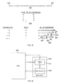
- Fig. 5 there is shown an illustrative example of the output encoding of the sequence of hierarchal codes 501 derived in the encoding example of Fig. 4.
- the purpose of output encoding is to reduce the total number of bits needed to represent a sequence of hierarchal codes derived in accordance with the invention. Such a reduction may be achieved by using well-known variable length coding techniques, such as Huffman encoding, which converts the fixed-length binary codes of the sequence of hierarchal codes into corresponding codes of variable length, i.e., variable number of bits. The total number of bits in the resulting output encoded sequence is less than that of the sequence of hierarchal codes.
- Huffman encoding which converts the fixed-length binary codes of the sequence of hierarchal codes into corresponding codes of variable length, i.e., variable number of bits.
- the total number of bits in the resulting output encoded sequence is less than that of the sequence of hierarchal codes.
- the sequence of hierarchal codes 501 derived in the example of Fig. 4 has 32 codes (shown in decimal representation), including a first code 505 and a last code 506. Each code of the sequence has a quantized value of 0, 1, 2 or 3.
- a table 502 is constructed listing the number of occurrences of each quantized value in the sequence 501. Huffman coding assigns an output code having the least number of bits to the most frequently occurring code values in the sequence 501 and codes having the largest number of bits to the least frequently occurring code values in the sequence 501.
- branches 507 and 508 extending from the two smallest number of occurrences and joined at a node 509 are first drawn. The sum 8 of the numbers 2 and 6 which are joined by branches 507 and 508 is assigned to node 509. Next, branches 510 and 511 extending respectively from the two smallest unjoined numbers, 8 and 8, and joined at a node 512 are drawn. The sum 16 of the numbers 8 and 8 which are joined by branches 510 and 511 is assigned to node 512.
- branches 513 and 514 extending respectively from the last two unjoined numbers 16 and 16 and joined at a node 515 are drawn.
- the sum 32 of the numbers 16 and 16 which are joined by branches 513 and 514 is assigned to node 512.
- bit value of 1 is assigned to the lower branch of each pair of joined branches, and a bit value of 0 is assigned to the higher branch of each pair of joined branches.
- the Huffman code for each code value of the sequence 501 is formed by taking the bit values associated with the branches in the path extending from the number of occurrences of the code value to the remaining unjoined number, 32, in order of increasing significance.
- An important feature of the invention is that it provides hierarchal image data which when output encoded with an appropriate data compression coding technique, such as variable length coding, provides a relatively high data compression ratio, the data compression ratio being the ratio of the number of bits in the output encoded image data to the number of bits in the digitized original image.
- the reason for the relatively high data compression ratio is that the histogram of the intensity values of the original digitized image tends to be relatively flat, and, consequently, the histogram of the respective cyclic differences between pairs of intensity values of the digitized original image is sharply peaked at the value zero.
- the application of variable length coding to a sequence of such cyclic differences results in a corresponding variable length code sequence in which the shortest code predominates, as may be seen from the Huffman coding example of Fig. 5.
- a further increase in data compression ratio may be obtained by detecting any large monotone areas in the image prior to encoding. Since monotone areas can be efficiently coded by a single intensity value and additional codes defining the extent of the monotone area, the sequence of hierarchal codes representing the image need not include the cyclic differences corresponding to intensity values in the monotone areas.
- the image encoding and decoding techniques in accordance with the invention may be used in conjunction with known prediction techniques to further increase the image data compression ratio. Since the encoded image can often be recognized by its general features, which are repeated several times throughout the sequence of hierarchal codes representing the image, the decoder by analyzing only a portion of the sequence of hierarchal codes can predict the remainder of the sequence by identifying the image from a file of such images stored at the receiver.
- the hardwired basic unit 603 includes a controller 602 which addresses a RAM 604 to read selected pairs of primary array values and a selected primary array value in accordance with the selection procedure specified in the flow diagram 200 of Fig. 2.
- the selected pairs of primary array values and the single selected primary array value are provided in sequence to a cyclic unit 601 forming part of the basic unit 603.
- the cyclic unit 601 under the control of the controller 602 computes the cyclic difference of each pair of primary array values it receives and provides the difference to the RAM 604. The difference is stored in the RAM 604 at an address provided by the controller 602. The single selected primary array value received by the cyclic unit is returned to the RAM 604 for storage at an address provided by the controller 602.
- FIG. 7 there is shown a schematic diagram of an exemplary feedback shift register circuit 700 of the type which may be used as the cyclic unit 601 in the basic unit 603 of Fig. 6.
- the circuit 700 is formed by interconnecting two type-D flip-flops 701 and 702. For each selected pair of primary array values, V1 and V2, received by the cyclic unit, the cyclic difference between those values is obtained by loading the value of V1 into the shift register and then applying a number of clock pulses equal to the value of V2 to each of the flip-flops 701 and 702.
- the primary array values V1 and V2 are each binary codes of two bits.
- V1 is first loaded into the shift register 700 by clearing the flip-flops 701 and 702 and applying the respective bit values of V1 to the SET inputs of those flip-flops. A series of clock pulses equal in number to V2 are then applied to each flip-flop. The binary code of the difference, d, between V1 and V2 is then taken from the Q outputs of the flip-flops 701 and 702.
- An exemplary circuit for converting the value V2 into a series of clock pulses equal in number to V2 comprises a clock generator 703 coupled to the clock inputs of the flip-flops 701 and 702 through a 2-input AND gate 704.
- the output of the AND gate 704 is also received by a binary counter 705.
- the state of the binary counter 705 is compared with V2 in a digital comparator 706, the output of which is connected through an inverter 707 to the other input of the AND gate 704.
- the AND gate 704 is enabled to pass the clock pulses from the clock generator 703.
- the controller 602 of the basic unit 603 of Fig. 6 for use in the encoder section 101 of Fig. 1 may be implemented as a hardwired finite state circuit based on the encoding flow diagram 200 of Fig. 2.
- the design of such a circuit is well known to those skilled in the art of digital circuit design and is therefore not further described. It is therefore apparent that the encoding procedure in accordance with the present invention may be implemented with relatively simple circuits.
- a flow diagram 800 of the decoding program routine which is executed by the processor 9 of the decoder section 102 of the image coder-decoder system 100 of Fig. 1.
- the flow diagram 800 specifies a decoding process for converting a sequence of hierarchal codes derived in the manner described above in connection with Figs. 2, 3, and 4 into a primary array of values representative of the encoded image.
- the process specified by the flow diagram 800 is the inverse of that specified by the flow diagram 200 of Fig. 2.
- the integers M and N denote the number of rows and the number of columns of the primary array, respectively.
- Block 802 of the flow diagram 800 represents the step of reading the first code, d, in the sequence of hierarchal codes from the RAM 10.
- this first code, d is the primary array value V(0,0) belonging in the first row and the first column. Therefore, the first code of the sequence of hierarchal codes is stored in a location in the RAM 10 corresponding to the first row and first column of the primary array.
- Block 803 of the flow diagram 800 represents varying the row index, i, from M-2 q to 0 in steps of 2 q and varying the column index, j, from N-2 p to 0 in steps of 2 p .
- the next code in the sequence of hierarchal codes is read from the RAM 10 as represented by block 804.
- a pair of primary array values, V1 and V2 are then derived in the steps represented by blocks 805-806.
- the value V1 is taken as the value, V(i,j) belonging in the i th row and j th column of the primary array.
- the value V2 is computed by taking the modulo K difference between the value of V1 as obtained in the step of block 805, and the code, d, read in the step of block 804.
- the modulus K is equal to 2 b , where b is the number of bits in each code of the sequence of hierarchal codes and is also the number of bits in each primary array value.
- An example of taking the modulo 4 difference between V1 and d to obtain V2 is illustrated by the table 900 of Fig. 9.
- the values V1, V2 and d are integers from 0 to 3. Therefore, each value can be represented by a 2 bit code, and a modulus of 4 if appropriate for taking the cyclic difference between V1 and d.
- the position in the primary array where the value V2 obtained in the step of block 806 belongs depends on whether the code read in the step of block 804 was derived in a horizontal pass or a vertical pass. If derived in a horizontal pass, the value V2 computed in the step of block 806 belongs in the i th row and the (j+2 p-1 ) th column of the primary array. If obtained in a vertical pass, the value of V2 computed in the step of block 806 belongs in the (i+2 q-1 ) th row and j th column of the primary array. The values V1 and V2 obtained in the steps of block 805 and 806, respectively, are then stored in appropriate locations in the RAM 10.
- Block 808 of the flow diagram 800 represents the step of decrementing the parameter p by 1 after each horizontal decoding pass or decrementing the parameter q by 1 after each vertical decoding pass.
- the decision block 809 represents a test to determine whether the parameter p is equal to 0 end the parameter q is equal to 0 each time p or q is decremented. If the test is negative, the program routine proceeds to the next horizontal or vertical decoding pass as determined by the encoding procedure used in accordance with the flow diagram 200 of Fig. 2. If the test is affirmative, indicating that the decoding procedure is completed, the decoding program routine represented by the flow diagram 800 is terminated.
- decmain5.c An exemplary decoding program routine, decmain5.c, is now described.
- the decmain5.c routine corresponds to the flow diagram 800 with the following exceptions: to facilitate debugging the decmain5.c routine is written in straight line code instead of using loops, as in the flow diagram 800; the order for deriving V1 and V2 is inverted from that of flow diagram 800 and the modulo K difference is taken between V2 and d instead of between V1 and d, as in the flow diagram 800; the first code in the sequence of hierarchal codes is taken as the value in the last row and last column of the primary array instead of the value in the first row and first column, as in the flow diagram 800; and the offsets of modulo K differences provided by the codmain5.c routine are removed by the decmain5.c routine.
- the decoding procedure specified by the flow diagram 800 may also be implemented with a hardwired basic unit as illustrated in the block diagram 600 of Fig. 6.
- the controller 602 addresses the RAM 604 to read the first code, d, of the sequence of hierarchal codes stored in the RAM 604.
- the first code is received by the cyclic unit 601, which causes that code to be stored at an address specified by the controller 602, the address corresponding to the first row and first column of the primary array.
- the controller 602 addresses the RAM to read a next code of the sequence of hierarchal codes, and a previously stored primary array value from a column and row position determined in accordance with block 803 of the flow diagram 800.
- the primary array value and the next code are received by the cyclic unit 601, which takes the modulo K difference therebetween and provides that difference to be written in memory at an address provided by the controller 602, the address corresponding to a primary array position determined in accordance with block 807 of the flow diagram 800.
- the decoding procedure continues in the manner specified by the flow diagram 800 until all values of the primary array have been derived from the sequence of hierarchal codes.
- the cyclic unit for the decoder section may be implemented as the feedback shift register circuit of the type depicted by the schematic diagram of Fig. 7.
- the controller 602 may be implemented as a finite state circuit based on the procedure specified by the flow diagram 800. The design of such a circuit is well known to those skilled in the art of digital circuit design and is therefore not further described.
- the encoding and decoding techniques in accordance with the invention are carried out serially, it will be recognized by those skilled in the art that such encoding and decoding techniques may be carried out in parallel, since the computation of one cyclic difference between a pair of primary array values or between a primary array value and a hierarchal code is independent of the computation of all other cyclic differences between other pairs of primary array values or between other combinations of primary values and hierarchal codes. Therefore, the implementation of the image encoding and decoding techniques of the invention using known parallel processing techniques would be an obvious alternative to those skilled in the art.
- the sequence of hierarchal codes includes one selected primary array value, as its first value, and the remaining hierarchal codes are cyclic differences of selected distinct pairs of primary values.
- the X selected primary array values may be those which give rise to large cyclic differences, and therefore the encoding of those values would not improve the data compression ratio when the sequence of hierarchal codes are output encoded. By leaving those primary array values uncoded, except for output encoding, the decoding of the sequence to reconstruct the primary array is accordingly simplified.
- Another important feature of the invention is the relatively high immunity of the image encoding and decoding technique to noise. Unlike known hierarchal image encoding and decoding techniques, the influence of an error on the reconstructed image is very small.
- An error in a given code in the sequence merely causes a shift in the intensity values derived after decoding with the erroneous code.
- an error in the first code of the sequence will result in a uniform shift in each of the decoded primary array values
- an error in the second code of the sequence will result in a shift half of the decoded primary array values and errors in subsequent codes will result in intensity shifts in a diminishing number of decoded primary array values.
- Such shifts in the intensity values of the primary array are less objectionable than the image distortions produced by errors in known hierarchal coding and decoding techniques.
- the primary array of intensity values from which a sequence of hierarchal codes is derived need not be the digitized original image, i.e., the pixel intensity value array, but may be the digitized original image after block encoding or sub-band encoding by known techniques.
- the primary array may also be a transform of the digitized original image obtained from a known two-dimensional transformation technique, such as the Fourier transform or the cosine transform.
Landscapes
- Health & Medical Sciences (AREA)
- Engineering & Computer Science (AREA)
- Signal Processing (AREA)
- Multimedia (AREA)
- Heart & Thoracic Surgery (AREA)
- Biomedical Technology (AREA)
- Life Sciences & Earth Sciences (AREA)
- Animal Behavior & Ethology (AREA)
- General Health & Medical Sciences (AREA)
- Public Health (AREA)
- Veterinary Medicine (AREA)
- Vascular Medicine (AREA)
- Reproductive Health (AREA)
- Image Processing (AREA)
- Compression, Expansion, Code Conversion, And Decoders (AREA)
- Pharmaceuticals Containing Other Organic And Inorganic Compounds (AREA)
- Compression Of Band Width Or Redundancy In Fax (AREA)
- Compression Or Coding Systems Of Tv Signals (AREA)
- Orthopedics, Nursing, And Contraception (AREA)
Abstract
Description
- This invention relates to a system and a method for the hierarchal encoding and decoding of an image.
- Hierarchal encoding of images is known and has been proposed as an alternative to conventional line-by-line image encoding techniques for the transmission of images over communication channels of restricted bandwidth. Using hierarchal encoding, data corresponding to gross approximations of an image are transmitted first, followed by data corresponding to more refined approximations until the final image is transmitted. Therefore, the quality of the reconstructed image at the receiver is progressively improved as more image data is received.
- One of the principal advantages of progressive image transmission using hierarchal encoding is the early recognition of the received image before transmission of the final image is completed. This is so because in many instances an early coarse approximation of an image is sufficient to permit identification of what is contained in the final image.
- Related to early recognition of the transmitted image is the possibility of reducing the amount of data required for the transmission of an image. By aborting the transmission after receiving a satisfactory approximation of the image but before transmission of the final image is completed, the amount of data required for the transmission of the image is effectively reduced.
- Hierarchal encoding of images is typically implemented by processing the information in an image to generate an explicit pyramidal data structure. Such a data structure contains multiple levels, each representing a successive approximation of the final image with the lowest level at the base of the pyramid representing the final image. Transmission of the pyramidal data structure begins at the highest level, i.e., at the vertex of the pyramid, followed by the transmission of successive lower levels.
- Known techniques for implementing hierarchal encoding of images to obtain pyramidal data structures are described in U.S.-A-4,222,076 to Knowlton and U.S.-A-4,698,689 to Tzou. The Knowlton technique uses a look-up table based algorithm to format spatial domain grey-scale values of pixels into a pyramidal structure, each formatted value being the approximate average of paired grey-scale values. The Tzou technique takes the two-dimension transform of block encoded grey-scale values of pixels and quantizes the transform coefficients to obtain a pyramidal data structure.
- The encoding and decoding functions used in Knowlton and Tzou require large computational and storage overhead for their implementation. Such overhead becomes a serious drawback when it is desired to implement a complete image coder-decoder (CODEC) as an integrated circuit, since the fabrication yield of such an integrated circuit decreases rapidly as the complexity or size of the circuit is increased. Therefore, a need clearly exists for a hierarchal, spatial domain image encoding and decoding technique using relatively simple encoding and decoding functions which do not require complex circuits, extensive computations or look-up tables for their implementation. Furthermore, a need exists for a hierarchal image encoding and decoding technique which provides high noise immunity and high data compression ratio, even without prematurely aborting the hierarchal transmission, when used in conjunction with an appropriate data compression output encoding technique, such as variable length encoding.
- The foregoing shortcomings of the prior art are overcome and the aforementioned needs are substantially satisfied by the present invention, which in one aspect is a system for the hierarchical encoding of an image comprising memory means having a multiplicity of addressable storage locations for storing data; means for receiving first coded values representative of intensities of picture elements of an image, the first coded values being stored in a primary array in the memory means, the primary array having M rows and N columns where M and N are predetermined integers; and first encoding means responsive to the first coded values for generating in a number of passes a sequence of second coded values, stored in respective locations in the memory means and hierarchically arranged to represent the progressively improved approximation of the image, said first encoding means selecting a predetermined number of distinct pairs of first coded values and determining the
respective modulo 2b difference of these selected pairs during each pass where b is the number of bits used to represent a first coded value, such that the sequence of second coded values comprises MxN second coded values having X selected first coded values followed by a total of Yrespective modulo 2b cyclic differences of a total of Y selected distinct pairs of first coded values, where X is an integer less than MxN and Y is an integer equal to MxN-X; and second encoding means responsive to the second coded values for generating a sequence of output codes (using known data compression output encoding techniques, such as variable length coding) corresponding to the sequence of second coded values. - Preferably, the sequence of second coded values has as its first code a selected first code value followed by MxN-1 respective cyclic differences of MxN-1 selected distinct pairs of first code values.
- Preferably the M rows of the primary array include a first row, the N columns of the primary array include a first column and the selected first coded value is the value in the first row and the first column of the primary array.
- Advantageously, the first encoding means comprises: means for selecting pairs of first coded values by making horizontal and vertical passes, in each horizontal pass pairs of first coded values, V₁ and V₂, are selected in accordance with the relations V₁=V(i,j) and


- Preferably, the means for selecting pairs of first coded values makes alternating horizontal and vertical passes.
- Advantageously, the system further comprises image scanning means for providing the first coded values representative of the intensities of the picture elements of the image.
- Preferably, the image scanning means includes means for decomposing the image into a pixel array having M rows and N columns, and means for deriving binary coded values corresponding to respective image intensities of the pixels.
- Another aspect of the present invention is a system for hierarchical decoding of an image comprising means for receiving a sequence of output encoded values representative of an image; memory means having a multiplicity of addressable storage locations for storing data; and first decoding means responsive to the sequence of output encoded values for providing a corresponding sequence of first coded values stored in respective locations of the memory means; characterized by second decoding means responsive to the sequence of first coded values for deriving a primary array of second coded values stored in respective locations in the memory means, the primary array having M rows and N columns, where M and N are predetermined integers, the sequence of first coded values including X values belonging to specified positions of the primary array followed by a total of Y
respective modulo 2b cyclic differences - where b is the number of bits used to represent a second coded value - of a total of Y distinct pairs of values belonging to specified positions of the primary array, where X is an integer less than MxN and Y is an integer equal to MxN-X; and third decoding means responsive to the primary array of second coded values for providing display signals representative of the image. - Preferably, the sequence of first coded values begins with one value belonging to a specified position in the primary array and the following MxN-1 respective cyclic differences of MxN-1 distinct pairs of values belonging to specified positions in the primary array
- Advantageously, the second decoding means includes means for deriving MxN-1 distinct pairs of second coded values in horizontal and vertical passes, in each horizontal pass pairs of second coded values, V₁ and V₂, are derived from respective sequential first coded values, d, in accordance with the relations V₁=V(i,j) and


- Preferably, the means for deriving the MxN-1 distinct pairs of second coded values makes alternating horizontal and vertical passes.
- Advantageously, the system further comprises display means responsive to the display signals provided by the third decoding means for presenting the image represented by the display signals.
- Still further aspects of the present invention are a method for the hierarchal encoding of an image and a method for the hierarchal decoding an image as carried out, for example, by the foregoing system for the hierarchal encoding and decoding of an image, respectively.
- The invention will be better understood from the following detailed description of the exemplary embodiments thereof taken in conjunction with the accompanying drawings, in which:
- Fig. 1 is a block diagram of an image encoder-decoder system in accordance with an exemplary embodiment of the invention;
- Fig. 2 is a flow diagram of the encoding program routine of the encoder processor in accordance with an exemplary embodiment of the invention;
- Fig. 3 is a table illustrative of the
modulo 4 cyclic difference, d, between 2-bit binary values V₁ and V₂; - Fig. 4 are diagrams representing the primary array and undersampled arrays with corresponding sequences of hierarchal codes derived therefrom, the diagrams being illustrative of the horizontal and vertical passes of the encoding procedure in accordance with an exemplary embodiment of the invention;
- Fig. 5 illustrates the conversion of the hierarchal codes, derived by the encoding procedure illustrated in Fig. 4, into corresponding Huffman codes;
- Fig. 6 is a more detailed block diagram of the encoder or decoder processor in accordance with an alternative embodiment of the present invention;
- Fig. 7 is a circuit diagram of a feedback shift register of the type useful as the cyclic unit of the encoder or decoder processor of Fig. 6 and a table showing the input and output states of the feedback shift register circuit;
- Fig. 8 is a flow diagram of the decoding program routine of the decoder processor in accordance with an exemplary embodiment of the invention; and
- Fig. 9 is a table illustrative of taking the
modulo 4 cyclic difference between V₁ and d to obtain V₂. - Throughout the figures of the drawings the same reference numerals are used to denote like components, parts, features and process steps.
- Referring now to Fig. 1, there is shown a block diagram 100 of an image coder-decoder system in accordance with an exemplary embodiment of the invention. The coder-
decoder system 100 includes anencoder section 101 and adecoder section 102. Theencoder section 101 has aconventional image scanner 1 for performing a line-by-line scan of an image (not shown) and providing analog signals representative of the scanned image. Theimage scanner 1 may be one which provides either grey-scale or colour operation. In the case of grey-scale operation, the analog scan signals provided by the image scanner represent the light intensity values along each scan line. In the case of colour operation, the analog scan signals provided by the image scanner represent the light intensity values along each scan line as obtained through red, green, and blue spectral filters, respectively. Thus, for colour operation the image scanner provides three times the intensity value information provided in grey-scale operation. For purposes of the present invention, colour images are encoded and decoded in the same manner as grey-scale images, except that the intensity values obtained through each spectral filter are encoded and decoded separately. It should be noted that in certain special image scanning applications, such as the scanning of an astronomical image, the intensity values provided by the image scanner may be for electromagnetic radiation having wavelengths outside of the visible spectrum. Moreover, the principles of the present invention are equally applicable to images obtained with non-electromagnetic radiation such as sonar images. - Typically, the image scanner scans the image horizontally from left to right, beginning at the top of the image and progressing on a line-by-line basis to the bottom of the image. The number of scanning lines used depends on the desired vertical resolution, a typical number being 256 lines.
- The
encoder section 101 also includes adigitizer 2, which divides each scan line into a finite number of segments, called pixels. Furthermore, thedigitizer 2 quantizes the light intensity value in each segment to a nearest preset value, i.e., a quantization level, and represents the quantized intensity value as a binary code. The conversion of the analog intensity value signals provided by theimage scanner 1 into binary codes is called pulse code modulation (PCM), and each binary code represents the light intensity value of a particular pixel of the image. The number of pixels per scan line depends on the desired horizontal resolution, a typical number being 256 pixels per line. The number of bits used for the binary code representing the light intensity value of each pixel depends on the desired intensity value resolution. The higher the intensity value resolution, the greater is the number of bits required to represent the light intensity value of each pixel. The output of thedigitizer 2 is commonly referred to as the digitized original image or pixel intensity value array. - It should be noted that the respective functions of the
image scanner 1 and thedigitizer 2 may be combined in a single device, called a digital scanner. - The digitized original image provided by the
digitizer 2 is stored in a Random-Access Memory (RAM) 3 of theencoder section 101 as a primary array of binary coded intensity values, the primary array having M rows and N columns, where M is equal to the number of scan lines used and N is equal to the number of pixels per scan line. Thedigitizer 2 contains appropriate circuitry for addressingRAM 3 for writing the digitized image in respective locations thereof. Theencoder section 101 further includes a conventionaldigital processor 4, which executes an encoding program routine for converting the digitized image stored in theRAM 3 into a sequence of hierarchal codes representing the digitized original image. The sequence of hierarchal codes are also stored in respective locations in theRAM 3. - The
encoder section 101 of the image encoder-decoder system 100 has anoutput encoder 5 for converting the sequence of hierarchal codes stored in theRAM 3 into a corresponding sequence of appropriate output codes providing a lossless data compression of the sequence of hierarchal codes prior to transmission. The output codes, which are stored in theRAM 3, may be in the form of a known variable length code, such as the Huffman code. Furthermore, theencoder section 101 has atransmitter 6 for providing an appropriate carrier signal suitable for transmission over acommunications channel 12. Thetransmitter 6 modulates the carrier signal with the sequence of output codes stored in theRAM 3. Thecommunications channel 12 may be any suitable medium for conducting the modulated carrier signal from thetransmitter 6, such as a telephone line, an optical fibre, a radio frequency or microwave wireless link. - The
decoder system 102 of the image code-decoder system 100 includes areceiver 7 coupled to acommunications channel 13 for receiving a carrier signal modulated with an output encoded sequence of hierarchal codes representing an image being transmitted. Thereceiver 7 demodulates the carrier signal to extract the output encoded sequence of hierarchal codes and stores the same in respective locations in aRAM 10 forming part of thedecoder section 102. Anoutput decoder 8 is included in thedecoder section 102 for converting the output encoded sequence of hierarchal codes in theRAM 10 into a corresponding sequence of hierarchal codes, which are also stored in respective locations in theRAM 10. Thedecoder section 102 further includes a conventionaldigital processor 9 which executes a decoding program routine for converting the sequence of hierarchal codes in theRAM 10 into a primary array of intensity values, the primary array of intensity values also being stored in respective locations in theRAM 10. - The
decoder section 102 further includes adisplay device 11 for converting the primary array of intensity values in theRAM 10 into appropriate display signals representing the image being transmitted. The image is then presented on a video screen of thedisplay device 11. - It should be noted that the
encoder section 101 anddecoder section 102 of the exemplary image coder-decoder system 100 are symmetrical in that each component, except for theRAMs receiver 7 performs the inverse of the function of thetransmitter 6, and thevideo display device 11 performs the inverse of the combined functions of theimage scanner 1 and thedigitizer 2. - The image encoding and decoding techniques of the invention were tested using a Sun Microsystems, Inc. SUN3 workstation serving as the
processor 4,RAM 3 andoutput encoder 5 of theencoder section 101 and also serving as theprocessor 9,RAM 10 andoutput decoder 8 of thedecoder section 102. In the same test the video monitor connected to a SUN2 workstation by the same manufacturer was used as thedisplay device 11 of thedecoder section 102. The functions of theoutput encoder 5 and theoutput decoder 8 were performed using respective program routines executed by the SUN3 workstation processor. - An advantageous implementation of the image coder-
decoder system 100 is to provide thedigitizer 2, theprocessor 4, theRAM 3, theoutput encoder 5 and thetransmitter 6 of theencoder section 101, and theprocessor 9, theRAM 10, theoutput decoder 8 and thereceiver 7 of thedecoder section 102 on a single integrated circuit chip. In such an implementation theRAM 3 and theRAM 10 may share the same RAM array, and a single appropriately programmed microprocessor may perform the functions of theprocessors output encoder 5 and theoutput decoder 8. Alternatively, the respective functions of theprocessors output encoder 5 and theoutput decoder 8 may all be implemented with hard-wired circuits in the integrated circuit chip. It is also possible to incorporate theimage scanner 1, excluding certain optical components, as an array of charged-coupled devices (CCD's) on the same integrated circuit chip as the above-mentioned components of the image coder-decoder system. - Turning now to Fig. 2 there is shown a flow diagram representative of the encoding program routine executed by the
processor 4 of theencoder section 101 in accordance with an exemplary embodiment of the invention. The program routine represented by the flow diagram 200 provides for converting the primary array of intensity values stored in theRAM 3 of the encoder section into a sequence of hierarchal codes, the number of codes being equal to the number of intensity values in the primary array. The first code in the sequence of hierarchal codes is the binary coded intensity value in the first row and first column of the primary array. The remaining codes in the sequence are the respective modulo K differences of MxN-1 distinct pairs of intensity values of the primary array. The distinct pairs of intensity values of the primary array are selected in a prescribed manner by making horizontal and vertical passes through the primary array. Inblock 201 of the flow diagram 200, parameters p and q are initialized before the first pass. If the first pass is a horizontal pass, p is set to 1 and q is set to 0. If the first pass is a vertical pass, then q is set to 1 and p is set to 0. The parameter p has values from 0 to n, where n=log₂N, and is incremented by 1 before each horizontal pass. The parameter q has values from 0 to m, where m=log₂M, and is incremented by 1 before each vertical pass. - The position of an intensity value in the primary array is uniquely specified by a row index, i, indicating the row of the primary array in which the value is located, and a column index, j, indicating the column of the primary array in which the value is located. As represented by
block 202 of the flow diagram 200, in each horizontal or vertical pass the row index, i, is varied from 0 to M-2q in steps of 2q, and the column index, j, is varied from 0 to M-2p in steps of 2p. -
Block 203 of the flow diagram 200 specifies that in each horizontal pass distinct pairs of primary array values, V₁ and V₂, are selected in accordance with the relations V₁=V(i,j) and

- As represented by
block 204 of the flow diagram 200, for each distinct pair of primary array values, V₁ and V₂, selected in a horizontal or vertical pass a modulo K cyclic difference, d, between V₁ and V₂ is computed, where K=2b and b is the number of bits in each binary-coded primary array value. A table useful for computing themodulo 4 cyclic difference between values V₁ and V₂ is shown in Fig. 3. In that table both V₁ and V₂ have integer values between 0 and 3 and can therefore be represented by a 2-bit binary code. Accordingly, a modulus of 4 is appropriate for taking the difference between V₁ and V₂. - In
block 205 of the flow diagram 200, each modulo K difference between distinct pairs of primary array values computed inblock 204 is stored sequentially in memory. - As represented by
block 206 of the flow diagram 200, the parameter p is incremented by 1 prior to each horizontal pass, and the parameter q is incremented by 1 prior to each vertical pass. - The
decision block 207 represents a test to determine whether the parameter p equals n and the parameter q equals m after each incrementation of p or q. If the test is negative, a new horizontal pass or vertical pass is made, as determined by preestablished procedure. If the test is affirmative, the value in the first row and first column of the primary array is stored as the first code in the sequence of hierarchal codes, in accordance withblock 208 of the flow diagram 200, and the encoding of the primary array is completed. - An exemplary encoding program routine, codmain5.c, for a 256x256 pixel image is now described. The codmain5.c routine corresponds to the flow diagram 200 with the following exceptions: to facilitate debugging the codmain5.c routine is written in equivalent straight line code instead of the loops indicated in the flow diagram 200; in codmain5.c each pair of values V₁ and V₂ are derived in an order opposite to that specified in the flow diagram 200; a modulo K difference, d, is taken between V₂ and V₁ instead of between V₁ and V₂, as indicated in the flow diagram 200, and is offset by an arbitrary amount, 100, to facilitate image recognition when an image is generated from the sequence of hierarchal codes without decoding; the first code in the sequence of hierarchal codes is the value in the last row and last column of the primary array instead of the value in the first row and first column, as indicated in the flow diagram 200; and the sequence of hierarchal codes are stored in reverse order by codmain5.c. A routine invert.c is used to invert the sequence stored by codmain5.c into its proper order for hierarchal transmission.
- Referring now to Fig. 4, there are shown diagrams representing the
primary array 401 and undersampled arrays 402-406 derived from theprimary array 401 to illustrate the encoding process represented by the flow diagram 200 of Fig. 2. For purposes of the illustration, theprimary array 401 is assumed to have 4 rows and 8 columns (i.e., M=4 and N=8) and to have intensity values in the range from 0 to 3 in integer steps. Accordingly, theprimary array 401 is represented as a grid having 32 positions, and each grid position has a number from 0 to 3 representing an intensity value and another number from 1 to 32 at the upper right hand corner denoting the position in the grid. As shown in the primary array diagram 401, the first pass is a horizontal pass in which distinct adjoining pairs of primary array values, as indicated by the arrows, are selected along each row from left to right, beginning with the first row and progressing downward to the last row. For each pair of primary array values selected in sequence, themodulo 4 difference between the first value and the second value of the pair is computed in accordance with the table of Fig. 3. The sequence of modulo 4 differences between the pairs of primary array values selected in the first horizontal pass is shown immediately beneath the primary array diagram 401. - Following the first horizontal pass, a vertical pass is made as illustrated by the undersampled array diagram 402. The undersampled array diagram 402 is derived by eliminating every second column from the primary array diagram 401. The first vertical pass is then made by selecting vertically adjoining pairs of value, as indicated by the arrows, from the undersampled array diagram 402 in sequence proceeding from left to right pairing the first two rows and then proceeding from left to right pairing the second two rows. The modulo 4 differences between the pairs of values selected in the first vertical pass are then computed in the sequence of their selection and added to the sequence obtained in the first horizontal pass, as shown by the sequence of values beneath the undersampled array diagram 402, in which the added values are underscored.
- After completing the first vertical pass a second horizontal pass is made, as illustrated by the undersampled array diagram 403. Diagram 403 is derived by eliminating every second row from the undersampled array diagram 402. In the second horizontal pass, horizontally adjoining pairs of values, as indicated by the arrows, are selected in sequence from the undersampled array diagram 403 proceeding from left to right in the first row and then proceeding from left to right in the second row. The
modulo 4 difference of each pair of values selected in the second horizontal pass is computed in the sequence of their selection and added to themodulo 4 differences computed in the first horizontal pass and the first vertical pass. The sequence of modulo 4 differences obtained after the second horizontal pass is shown beneath the undersampled array diagram 403, the added values in the sequence being underscored. - Following the second horizontal pass, a second vertical pass is made, as illustrated by the undersampled array diagram 404. Diagram 404 is derived by eliminating every second column from the undersampled array diagram 403. In the second vertical pass, vertically adjoining pairs of values, as indicated by the arrows, are selected in sequence proceeding from left to right. The
modulo 4 difference between each selected pair of values is computed in the sequence of their selection, in accordance with the table of Fig. 3. The computed sequence of modulo 4 differences computed in the second vertical pass are added to the sequence of differences computed in earlier passes, as shown in the sequence of values beneath the undersampled array diagram 404, in which the added values are underscored. - After completion of the second vertical pass, a third horizontal pass is made, as illustrated by the undersampled array diagram 405. Diagram 405 is derived by eliminating the second row from the undersampled array diagram 404. In the third horizontal pass, the cyclic difference between the single pair of horizontally adjoining values in the
undersampled array 405 is computed and added to the right of the sequence of modulo 4 differences computed in earlier passes, as shown in the sequence of values beneath the undersampled array diagram 405 in which the added values are underscored. Following the third horizontal pass, an undersampled array diagram 406 is derived by eliminating the second column (grid position 5) from the undersampled array diagram 405. Diagram 406 contains a single value, which is the value in the first row and first column of the primary array diagram 401. This value is added to the right of the sequence of modulo 4 differences obtained in the prior passes, as shown in the sequence of values beneath the undersampled array diagram 406 in which the added value is underscored. This sequence of values, when expressed as binary codes, is the sequence of hierarchal codes representative of the primary array of values in diagram 401. - Although the foregoing illustrative example uses alternating horizontal and vertical passes in selecting the distinct pairs of primary array values for computing the sequence of cyclic differences, the encoding process in accordance with the present invention contemplates other predetermined combinations of horizontal and vertical passes providing a procedure for the selection of distinct pairs of primary array values. In addition, the pair selection procedure may be such that the undersampled array for each vertical or horizontal pass is derived by eliminating every other column or row, respectively, of the previous undersampled array beginning with the first column or row instead of the second, as illustrated in the example of Fig. 4. Furthermore, the cyclic difference need not be taken between the first value and the second value of each selected pair as in the illustrative example, but may be taken between the second value and the first value of each selected pair. Moreover, the first code in the sequence of hierarchal codes need not be the value in the first row and first column of the primary array but may be another specified primary array value, such as the value in the last row and last column of the primary array. It should be noted that while the undersampled array diagrams 402-406 are useful for the purposes of illustrating the horizontal and vertical passes of the encoding procedure in accordance with the invention, such undersampled arrays need not be actually derived in the encoding process.
- Referring now to Fig. 5, there is shown an illustrative example of the output encoding of the sequence of
hierarchal codes 501 derived in the encoding example of Fig. 4. As mentioned above, the purpose of output encoding is to reduce the total number of bits needed to represent a sequence of hierarchal codes derived in accordance with the invention. Such a reduction may be achieved by using well-known variable length coding techniques, such as Huffman encoding, which converts the fixed-length binary codes of the sequence of hierarchal codes into corresponding codes of variable length, i.e., variable number of bits. The total number of bits in the resulting output encoded sequence is less than that of the sequence of hierarchal codes. A description of the well known Huffman encoding technique may be found in a textbook by A. J. Viterbi and J. K. Omura, entitled Principles of Digital Communication and Encoding, published by the McGraw-Hill Book Company and also in a textbook by R. Gallager, entitled Information Theory and Reliable Communication, published by J. Wiley and Bond, Inc., 1968. - The sequence of
hierarchal codes 501 derived in the example of Fig. 4 has 32 codes (shown in decimal representation), including afirst code 505 and alast code 506. Each code of the sequence has a quantized value of 0, 1, 2 or 3. A table 502 is constructed listing the number of occurrences of each quantized value in thesequence 501. Huffman coding assigns an output code having the least number of bits to the most frequently occurring code values in thesequence 501 and codes having the largest number of bits to the least frequently occurring code values in thesequence 501. - The assignment of Huffman codes to the code values of the
sequence 501 is illustrated by the branch diagram 503. To construct the branch diagram 503, the number of occurrences of each code value in thesequence 501 are listed in descending order.Branches node 509 are first drawn. Thesum 8 of thenumbers branches node 509. Next,branches node 512 are drawn. Thesum 16 of thenumbers branches node 512. The process continues untilbranches unjoined numbers node 515 are drawn. Thesum 32 of thenumbers branches node 512. - Following the construction of the branch diagram 503, a bit value of 1 is assigned to the lower branch of each pair of joined branches, and a bit value of 0 is assigned to the higher branch of each pair of joined branches. The Huffman code for each code value of the
sequence 501 is formed by taking the bit values associated with the branches in the path extending from the number of occurrences of the code value to the remaining unjoined number, 32, in order of increasing significance. - An important feature of the invention is that it provides hierarchal image data which when output encoded with an appropriate data compression coding technique, such as variable length coding, provides a relatively high data compression ratio, the data compression ratio being the ratio of the number of bits in the output encoded image data to the number of bits in the digitized original image. The reason for the relatively high data compression ratio is that the histogram of the intensity values of the original digitized image tends to be relatively flat, and, consequently, the histogram of the respective cyclic differences between pairs of intensity values of the digitized original image is sharply peaked at the value zero. The application of variable length coding to a sequence of such cyclic differences results in a corresponding variable length code sequence in which the shortest code predominates, as may be seen from the Huffman coding example of Fig. 5.
- A further increase in data compression ratio may be obtained by detecting any large monotone areas in the image prior to encoding. Since monotone areas can be efficiently coded by a single intensity value and additional codes defining the extent of the monotone area, the sequence of hierarchal codes representing the image need not include the cyclic differences corresponding to intensity values in the monotone areas.
- The image encoding and decoding techniques in accordance with the invention may be used in conjunction with known prediction techniques to further increase the image data compression ratio. Since the encoded image can often be recognized by its general features, which are repeated several times throughout the sequence of hierarchal codes representing the image, the decoder by analyzing only a portion of the sequence of hierarchal codes can predict the remainder of the sequence by identifying the image from a file of such images stored at the receiver.
- Turning now to Fig. 6, there is shown a block diagram 600 of a hardwired
basic unit 603, which may be substituted for theprocessor 4 and its encoding program routine in theencoding section 101 of the image coder-decoder 100 of Fig. 1. The hardwiredbasic unit 603 includes acontroller 602 which addresses aRAM 604 to read selected pairs of primary array values and a selected primary array value in accordance with the selection procedure specified in the flow diagram 200 of Fig. 2. The selected pairs of primary array values and the single selected primary array value are provided in sequence to acyclic unit 601 forming part of thebasic unit 603. - The
cyclic unit 601 under the control of thecontroller 602 computes the cyclic difference of each pair of primary array values it receives and provides the difference to theRAM 604. The difference is stored in theRAM 604 at an address provided by thecontroller 602. The single selected primary array value received by the cyclic unit is returned to theRAM 604 for storage at an address provided by thecontroller 602. - Referring now to Fig. 7, there is shown a schematic diagram of an exemplary feedback
shift register circuit 700 of the type which may be used as thecyclic unit 601 in thebasic unit 603 of Fig. 6. Thecircuit 700 is formed by interconnecting two type-D flip-flops flops shift register 700 by clearing the flip-flops flops - An exemplary circuit for converting the value V₂ into a series of clock pulses equal in number to V₂ comprises a
clock generator 703 coupled to the clock inputs of the flip-flops gate 704. The output of the ANDgate 704 is also received by abinary counter 705. The state of thebinary counter 705 is compared with V₂ in adigital comparator 706, the output of which is connected through aninverter 707 to the other input of the ANDgate 704. Thus, when the state of thebinary counter 705 is less than V₂ the output of thedigital comparator 706 is 0 and the ANDgate 704 is enabled to pass the clock pulses from theclock generator 703. When the state of thebinary counter 705 is equal to or greater than V₂, the output of thedigital comparator 706 goes to 1 to disable the ANDgate 704, and no further clock pulses are permitted to pass to the flip-flops flops - The
controller 602 of thebasic unit 603 of Fig. 6 for use in theencoder section 101 of Fig. 1 may be implemented as a hardwired finite state circuit based on the encoding flow diagram 200 of Fig. 2. The design of such a circuit is well known to those skilled in the art of digital circuit design and is therefore not further described. It is therefore apparent that the encoding procedure in accordance with the present invention may be implemented with relatively simple circuits. - Turning now to Fig. 8, there is shown a flow diagram 800 of the decoding program routine which is executed by the
processor 9 of thedecoder section 102 of the image coder-decoder system 100 of Fig. 1. The flow diagram 800 specifies a decoding process for converting a sequence of hierarchal codes derived in the manner described above in connection with Figs. 2, 3, and 4 into a primary array of values representative of the encoded image. The process specified by the flow diagram 800 is the inverse of that specified by the flow diagram 200 of Fig. 2. -
Block 801 of the flow diagram 800 represents the step of setting a parameter p to the value n and setting another parameter q to the value of m, where n=log₂N and m=log₂M. As before, the integers M and N denote the number of rows and the number of columns of the primary array, respectively. -
Block 802 of the flow diagram 800 represents the step of reading the first code, d, in the sequence of hierarchal codes from theRAM 10. In accordance with the encoding procedure of Fig. 2, this first code, d, is the primary array value V(0,0) belonging in the first row and the first column. Therefore, the first code of the sequence of hierarchal codes is stored in a location in theRAM 10 corresponding to the first row and first column of the primary array. -
Block 803 of the flow diagram 800 represents varying the row index, i, from M-2q to 0 in steps of 2q and varying the column index, j, from N-2p to 0 in steps of 2p. For each variation of the indices i and j, the next code in the sequence of hierarchal codes is read from theRAM 10 as represented byblock 804. A pair of primary array values, V₁ and V₂, are then derived in the steps represented by blocks 805-806. Inblock 805 the value V₁ is taken as the value, V(i,j) belonging in the ith row and jth column of the primary array. Inblock 806 the value V₂ is computed by taking the modulo K difference between the value of V₁ as obtained in the step ofblock 805, and the code, d, read in the step ofblock 804. - The modulus K is equal to 2b, where b is the number of bits in each code of the sequence of hierarchal codes and is also the number of bits in each primary array value. An example of taking the
modulo 4 difference between V₁ and d to obtain V₂ is illustrated by the table 900 of Fig. 9. In the table 900 the values V₁, V₂ and d are integers from 0 to 3. Therefore, each value can be represented by a 2 bit code, and a modulus of 4 if appropriate for taking the cyclic difference between V₁ and d. - As represented by
block 807, the position in the primary array where the value V₂ obtained in the step ofblock 806 belongs depends on whether the code read in the step ofblock 804 was derived in a horizontal pass or a vertical pass. If derived in a horizontal pass, the value V₂ computed in the step ofblock 806 belongs in the ith row and the (j+2p-1)th column of the primary array. If obtained in a vertical pass, the value of V₂ computed in the step ofblock 806 belongs in the (i+2q-1)th row and jth column of the primary array. The values V₁ and V₂ obtained in the steps ofblock RAM 10. -
Block 808 of the flow diagram 800 represents the step of decrementing the parameter p by 1 after each horizontal decoding pass or decrementing the parameter q by 1 after each vertical decoding pass. Thedecision block 809 represents a test to determine whether the parameter p is equal to 0 end the parameter q is equal to 0 each time p or q is decremented. If the test is negative, the program routine proceeds to the next horizontal or vertical decoding pass as determined by the encoding procedure used in accordance with the flow diagram 200 of Fig. 2. If the test is affirmative, indicating that the decoding procedure is completed, the decoding program routine represented by the flow diagram 800 is terminated. - An exemplary decoding program routine, decmain5.c, is now described. The decmain5.c routine corresponds to the flow diagram 800 with the following exceptions: to facilitate debugging the decmain5.c routine is written in straight line code instead of using loops, as in the flow diagram 800; the order for deriving V₁ and V₂ is inverted from that of flow diagram 800 and the modulo K difference is taken between V₂ and d instead of between V₁ and d, as in the flow diagram 800; the first code in the sequence of hierarchal codes is taken as the value in the last row and last column of the primary array instead of the value in the first row and first column, as in the flow diagram 800; and the offsets of modulo K differences provided by the codmain5.c routine are removed by the decmain5.c routine.
- The decoding procedure specified by the flow diagram 800 may also be implemented with a hardwired basic unit as illustrated in the block diagram 600 of Fig. 6. Referring again to Fig. 6, the
controller 602 addresses theRAM 604 to read the first code, d, of the sequence of hierarchal codes stored in theRAM 604. The first code is received by thecyclic unit 601, which causes that code to be stored at an address specified by thecontroller 602, the address corresponding to the first row and first column of the primary array. Thereafter, thecontroller 602 addresses the RAM to read a next code of the sequence of hierarchal codes, and a previously stored primary array value from a column and row position determined in accordance withblock 803 of the flow diagram 800. The primary array value and the next code are received by thecyclic unit 601, which takes the modulo K difference therebetween and provides that difference to be written in memory at an address provided by thecontroller 602, the address corresponding to a primary array position determined in accordance withblock 807 of the flow diagram 800. The decoding procedure continues in the manner specified by the flow diagram 800 until all values of the primary array have been derived from the sequence of hierarchal codes. - As in the case of the basic unit for the encoder section, the cyclic unit for the decoder section may be implemented as the feedback shift register circuit of the type depicted by the schematic diagram of Fig. 7. The
controller 602 may be implemented as a finite state circuit based on the procedure specified by the flow diagram 800. The design of such a circuit is well known to those skilled in the art of digital circuit design and is therefore not further described. - Although in the foregoing illustrative examples, the encoding and decoding techniques in accordance with the invention are carried out serially, it will be recognized by those skilled in the art that such encoding and decoding techniques may be carried out in parallel, since the computation of one cyclic difference between a pair of primary array values or between a primary array value and a hierarchal code is independent of the computation of all other cyclic differences between other pairs of primary array values or between other combinations of primary values and hierarchal codes. Therefore, the implementation of the image encoding and decoding techniques of the invention using known parallel processing techniques would be an obvious alternative to those skilled in the art.
- In the encoding example of Figs. 2-4, the sequence of hierarchal codes includes one selected primary array value, as its first value, and the remaining hierarchal codes are cyclic differences of selected distinct pairs of primary values. In some instances, it may be desirable for the sequence of hierarchal codes to include more than one selected primary array value. For example, a primary array having M rows and N columns may be encoded into a sequence of MxN hierarchal codes having X selected primary array values and Y cyclic differences of Y selected distinct pairs of primary array values, where X is an integer less than MxN and

- Another important feature of the invention is the relatively high immunity of the image encoding and decoding technique to noise. Unlike known hierarchal image encoding and decoding techniques, the influence of an error on the reconstructed image is very small. An error in a given code in the sequence merely causes a shift in the intensity values derived after decoding with the erroneous code. Thus an error in the first code of the sequence will result in a uniform shift in each of the decoded primary array values, an error in the second code of the sequence will result in a shift half of the decoded primary array values and errors in subsequent codes will result in intensity shifts in a diminishing number of decoded primary array values. Such shifts in the intensity values of the primary array are less objectionable than the image distortions produced by errors in known hierarchal coding and decoding techniques.
- Various modifications to the preferred embodiment are envisaged. For example, the primary array of intensity values from which a sequence of hierarchal codes is derived need not be the digitized original image, i.e., the pixel intensity value array, but may be the digitized original image after block encoding or sub-band encoding by known techniques. Furthermore, the primary array may also be a transform of the digitized original image obtained from a known two-dimensional transformation technique, such as the Fourier transform or the cosine transform.
Claims (21)
- A system for the hierarchical encoding of an image comprising:
memory means having a multiplicity of addressable storage locations for storing data;
means for receiving first coded values representative of intensities of picture elements of an image, the first coded values being stored in a primary array in the memory means, the primary array having M rows and N columns where M and N are predetermined integers; and
first encoding means responsive to the first coded values for generating in a number of passes a sequence of second coded values, stored in respective locations in the memory means and hierarchically arranged to represent the progressively improved approximation of the image, said first encoding means selecting a predetermined number of distinct pairs of first coded values and determining the respective modulo 2b difference of these selected pairs during each pass, where b is the number of bits used to represent a first coded value, such that the sequence of second coded values comprises MxN second coded values having X selected first coded values followed by a total of Y respective modulo 2b cyclic differences of a total of Y selected distinct pairs of first coded values, where X is an integer less than MxN and Y is an integer equal to MxN-X; and
second encoding means responsive to the second coded values for generating a sequence of output codes corresponding to the sequence of second coded values. - A system as claimed in Claim 1, wherein the sequence of second coded values has as its first code a selected first coded value followed by MxN-1 respective cyclic differences of MxN-1 selected distinct pairs of first coded values.
- A system as claimed in Claim 2, wherein the M rows of the primary array include a first row, the N columns of the primary array include a first column and the selected first coded value is the value in the first row and the first column of the primary array.
- A system as claimed in Claim 2 or 3, wherein the first encoding means comprises:
means for selecting pairs of first coded values by making horizontal and vertical passes, in each horizontal pass pairs of first coded values, V₁ and V₂ are selected in accordance with the relations V₁ =V(i,j) and

means for taking the modulo K cyclic difference between each pair of first coded values selected in each horizontal and vertical pass, where K=2b and each modulo K difference has a position C in the sequence of second coded values determined by the relations
- A system as claimed in Claim 4, wherein the means for selecting pairs of first coded values makes alternating horizontal and vertical passes.
- A system as claimed in any preceding Claim, further comprising image scanning means for providing the first coded values representative of the intensities of the picture elements of the image.
- A system as claimed in Claim 6, wherein the image scanning means includes means for decomposing the image into a pixel array having M rows and N columns, and means for deriving binary coded values corresponding to respective image intensities of the pixels.
- A system for hierarchical decoding of an image comprising
means for receiving a sequence of output encoded values representative of an image;
memory means having a multiplicity of addressable storage locations for storing data; and
first decoding means responsive to the sequence of output encoded values for providing a corresponding sequence of first coded values stored in respective locations of the memory means; characterized by
second decoding means responsive to the sequence of first coded values for deriving a primary array of second coded values stored in respective locations in the memory means, the primary array having M rows and N columns, where M and N are predetermined integers, the sequence of first coded values including X values belonging to specified positions of the primary array followed by a total of Y respective modulo 2b cyclic differences - where b is the number of bits used to represent a second coded value - of a total of Y distinct pairs of values belonging to specified positions of the primary array, where X is an integer less than MxN and Y is an integer equal to MxN-X; and
third decoding means responsive to the primary array of second coded values for providing display signals representative of the image. - A system as claimed in Claim 8, wherein the sequence of first coded values begins with one value belonging to a specified position in the primary array followed by MxN-1 respective cyclic differences of MxN-1 distinct pairs of values belonging to specified positions in the primary array.
- A system as claimed in Claim 9, wherein the second decoding means includes means for deriving the MxN-1 distinct pairs of second coded values in horizontal and vertical passes, in each horizontal pass pairs of second coded values, V₁ and V₂, are derived from respective sequential first coded values, d, in accordance with the relations V₁=V(i,j) and


- A system as claimed in Claim 10, wherein the means for deriving the MxN-1 distinct pairs of second coded values makes alternating horizontal and vertical passes.
- A system as claimed in Claim 8, 9, 10 or 11, further comprising display means responsive to the display signals provided by the third decoding means for presenting the image represented by the display signals.
- A method for the hierarchical encoding of an image comprising the steps of:
deriving a primary array of first coded values representative of intensities of picture elements of the image, the primary array having M rows and N columns, where M and N are predetermined integers; and
deriving a sequence of second coded values representing a progressively improved approximation of the image from the first coded values by, in a number of passes, selecting a predetermined number of distinct pairs of first coded values, and determining the respective modulo 2b differences of these selected pairs during each pass where b is the number of bits used to represent a first coded value, so that the sequence of said second coded values thus comprises MxN second coded values derived by selecting X distinct first coded values, selecting a total of Y distinct pairs of first coded values, and taking the modulo 2b cyclic difference of each selected pairs of first coded values, where X is an integer less than MxN and Y is another integer equal to MxN-X, the sequence of second coded values comprising the selected first coded values followed by the respective modulo 2b cyclic differences of the selected pairs of first coded values; and
deriving a sequence of output codes corresponding to the sequence of second coded values. - A method according to Claim 13, wherein the M rows of the primary array include a first row and the N columns of the primary array include a first column and the selected first coded value is the value in the first row and the first column of the primary array.
- A method according to Claim 14 wherein the step of selecting MxN-1 distinct pairs of first coded values comprises making n horizontal passes and m vertical passes, where n=log₂N and m=log₂M, in each horizontal pass selecting pairs of first coded values, V₁ and V₂, according to the relations V₁=V(i,j) and V₂(i,j+2p-1). where V(i,j) is the first coded value in the ith row and jth column of the primary array, V(i,j+2p-1) is the first coded value in the ith row and (j+2p-1)th column of the primary array, i has values from 0 to M-2q in steps of 2q, j has values from 0 to N-2p in steps of 2p, p has values from 0 to log₂N and is incremented by 1 before each horizontal pass, q has values from 0 to log₂M and is incremented by 1 before each vertical pass, and in each vertical pass selecting pairs of first coded values, V₁ and V₂, according to the relations V₁=V(i,j) and


- A method according to Claim 15, wherein the step of making n horizontal and m vertical passes include making alternating horizontal and vertical passes.
- A method according to Claim 15 or 16, wherein the step of taking the modulo K cyclic difference between each pair of first coded values, V₁ and V₂, selected in each horizontal and vertical pass comprises taking the modulo K cyclic difference between V₁ and V₂.
- A method for the hierarchical decoding an image comprising the steps of:
deriving a sequence of MxN first coded values representative of intensities of picture elements of an image, where M and N are predetermined integers; and
deriving a primary array of corresponding second coded values from the sequence of first coded values, characterized in that the primary array comprises M rows and N columns and the sequence of first coded values has X distinct values belonging to specified positions of the primary array followed by a total of Y respective modulo 2b cyclic differences - where b is the number of bits used to represent a second coded value - of a total of Y distinct pairs of values belonging to specified positions of the primary array, where X is an integer less than MxN and Y is an integer equal to MxN-X; and
deriving display signals representative of the image from the primary array of second coded values. - A method according to Claim 18, wherein the sequence of second coded values begins with one value belonging to a specified position of the primary array followed by MxN-1 respective cyclic differences of MxN-1 distinct pairs of values belonging to specified positions of the primary array.
- A method according to Claim 19, wherein the step of deriving the primary array of second coded values comprises making n horizontal passes and m vertical passes, where n=log₂N and m=log₂M; in each horizontal pass deriving pairs of second coded values, V₁ and V₂, from respective sequential first coded values, d, according to the relations V₁=V(i,j) and


- A method according to Claim 20, wherein the step of making n horizontal and m vertical passes include making alternating horizontal and vertical passes.
Applications Claiming Priority (4)
| Application Number | Priority Date | Filing Date | Title |
|---|---|---|---|
| US146781 | 1988-01-22 | ||
| US07/146,781 US4858017A (en) | 1988-01-22 | 1988-01-22 | System and method for hierarchal image encoding and decoding |
| PCT/US1989/000178 WO1989006888A1 (en) | 1988-01-22 | 1989-01-23 | System and method for hierarchal image encoding and decoding |
| CA000614646A CA1325064C (en) | 1988-01-22 | 1989-09-29 | System and method for hierarchal image encoding and decoding |
Publications (2)
| Publication Number | Publication Date |
|---|---|
| EP0353289A1 EP0353289A1 (en) | 1990-02-07 |
| EP0353289B1 true EP0353289B1 (en) | 1994-06-08 |
Family
ID=25673161
Family Applications (1)
| Application Number | Title | Priority Date | Filing Date |
|---|---|---|---|
| EP89902431A Expired - Lifetime EP0353289B1 (en) | 1988-01-22 | 1989-01-23 | System and method for hierarchal image encoding and decoding |
Country Status (9)
| Country | Link |
|---|---|
| US (1) | US4858017A (en) |
| EP (1) | EP0353289B1 (en) |
| JP (1) | JPH03500597A (en) |
| KR (1) | KR920700597A (en) |
| AT (1) | ATE107106T1 (en) |
| CA (1) | CA1325064C (en) |
| DE (1) | DE68915886T2 (en) |
| NO (1) | NO905636D0 (en) |
| WO (1) | WO1989006888A1 (en) |
Families Citing this family (49)
| Publication number | Priority date | Publication date | Assignee | Title |
|---|---|---|---|---|
| US5095512A (en) * | 1988-10-24 | 1992-03-10 | Netexpress Systems, Inc. | Method and apparatus for manipulating image data employing an intermediate format |
| US5210623A (en) * | 1989-12-21 | 1993-05-11 | Eastman Kodak Company | Apparatus and method for quantizing and/or reconstructing multi-dimensional digital image signals |
| DE69131809T2 (en) * | 1990-09-04 | 2000-05-11 | Canon K.K., Tokio/Tokyo | Image processing method and device |
| US5414469A (en) * | 1991-10-31 | 1995-05-09 | International Business Machines Corporation | Motion video compression system with multiresolution features |
| US5521717A (en) * | 1992-02-03 | 1996-05-28 | Canon Kabushiki Kaisha | Image processing apparatus and method therefor |
| US5335088A (en) * | 1992-04-01 | 1994-08-02 | Xerox Corporation | Apparatus and method for encoding halftone images |
| US5592399A (en) * | 1993-05-26 | 1997-01-07 | Intel Corporation | Pipelined video encoder architecture |
| US5577134A (en) * | 1994-01-07 | 1996-11-19 | Panasonic Technologies, Inc. | Method and apparatus for encoding a segmented image without loss of information |
| JP3501301B2 (en) * | 1994-03-18 | 2004-03-02 | ソニー株式会社 | Input/Output Signal Switching Device |
| JP3302229B2 (en) * | 1994-09-20 | 2002-07-15 | 株式会社リコー | Encoding method, encoding / decoding method and decoding method |
| US6229927B1 (en) | 1994-09-21 | 2001-05-08 | Ricoh Company, Ltd. | Reversible embedded wavelet system implementation |
| US6873734B1 (en) | 1994-09-21 | 2005-03-29 | Ricoh Company Ltd | Method and apparatus for compression using reversible wavelet transforms and an embedded codestream |
| US5881176A (en) | 1994-09-21 | 1999-03-09 | Ricoh Corporation | Compression and decompression with wavelet style and binary style including quantization by device-dependent parser |
| US6549666B1 (en) | 1994-09-21 | 2003-04-15 | Ricoh Company, Ltd | Reversible embedded wavelet system implementation |
| JPH08180180A (en) * | 1994-12-26 | 1996-07-12 | Canon Inc | Electronic filing equipment |
| US6021259A (en) * | 1995-07-10 | 2000-02-01 | International Business Machines Corporation | Apparatus and method for conversion of structured data between different formats |
| US5867613A (en) * | 1995-09-29 | 1999-02-02 | Raytheon Company | High speed hardware loader for look-up table |
| US6873738B2 (en) * | 1995-10-02 | 2005-03-29 | Sony Corporation | Hierarchical image processor for encoding or decoding, and memory on the same chip |
| US5999656A (en) * | 1997-01-17 | 1999-12-07 | Ricoh Co., Ltd. | Overlapped reversible transforms for unified lossless/lossy compression |
| US5982938A (en) * | 1997-03-31 | 1999-11-09 | Iterated Systems, Inc. | System and method for compressing data using differential coding of coefficient addresses |
| SE511514C2 (en) * | 1997-05-13 | 1999-10-11 | Ericsson Telefon Ab L M | Method and apparatus for image compression |
| US6411395B1 (en) * | 1997-07-23 | 2002-06-25 | International Business Machines Corporation | Apparatus and method for conversion of data between different formats |
| US6044172A (en) * | 1997-12-22 | 2000-03-28 | Ricoh Company Ltd. | Method and apparatus for reversible color conversion |
| US6209055B1 (en) | 1998-10-29 | 2001-03-27 | International Business Machines Corporation | Method and apparatus for reducing noise induced among conductive lines |
| US6898323B2 (en) | 2001-02-15 | 2005-05-24 | Ricoh Company, Ltd. | Memory usage scheme for performing wavelet processing |
| US6859563B2 (en) | 2001-03-30 | 2005-02-22 | Ricoh Co., Ltd. | Method and apparatus for decoding information using late contexts |
| US6895120B2 (en) * | 2001-03-30 | 2005-05-17 | Ricoh Co., Ltd. | 5,3 wavelet filter having three high pair and low pair filter elements with two pairs of cascaded delays |
| US6950558B2 (en) | 2001-03-30 | 2005-09-27 | Ricoh Co., Ltd. | Method and apparatus for block sequential processing |
| US7062101B2 (en) * | 2001-03-30 | 2006-06-13 | Ricoh Co., Ltd. | Method and apparatus for storing bitplanes of coefficients in a reduced size memory |
| US7006697B1 (en) | 2001-03-30 | 2006-02-28 | Ricoh Co., Ltd. | Parallel block MQ arithmetic image compression of wavelet transform coefficients |
| US7581027B2 (en) | 2001-06-27 | 2009-08-25 | Ricoh Co., Ltd. | JPEG 2000 for efficent imaging in a client/server environment |
| US7280252B1 (en) | 2001-12-19 | 2007-10-09 | Ricoh Co., Ltd. | Error diffusion of multiresolutional representations |
| US7095907B1 (en) | 2002-01-10 | 2006-08-22 | Ricoh Co., Ltd. | Content and display device dependent creation of smaller representation of images |
| US7120305B2 (en) * | 2002-04-16 | 2006-10-10 | Ricoh, Co., Ltd. | Adaptive nonlinear image enlargement using wavelet transform coefficients |
| CN1663257A (en) * | 2002-04-19 | 2005-08-31 | 德国普莱特科技公司 | Wavelet transform system, method and computer program product |
| US7212681B1 (en) | 2003-01-15 | 2007-05-01 | Cisco Technology, Inc. | Extension of two-dimensional variable length coding for image compression |
| WO2004090808A2 (en) * | 2003-04-07 | 2004-10-21 | Definiens Ag | Computer-implemented system and method for progressively transmitting knowledge and computer program product related thereto |
| US7194137B2 (en) * | 2003-05-16 | 2007-03-20 | Cisco Technology, Inc. | Variable length coding method and apparatus for video compression |
| US7451381B2 (en) * | 2004-02-03 | 2008-11-11 | Phonex Broadband Corporation | Reliable method and system for efficiently transporting dynamic data across a network |
| US7499595B2 (en) * | 2004-08-18 | 2009-03-03 | Cisco Technology, Inc. | Joint amplitude and position coding for photographic image and video coding |
| US7499596B2 (en) * | 2004-08-18 | 2009-03-03 | Cisco Technology, Inc. | Amplitude coding for clustered transform coefficients |
| US7471840B2 (en) * | 2004-08-18 | 2008-12-30 | Cisco Technology, Inc. | Two-dimensional variable length coding of runs of zero and non-zero transform coefficients for image compression |
| US7454073B2 (en) * | 2004-06-15 | 2008-11-18 | Cisco Technology, Inc. | Video compression using multiple variable length coding processes for multiple classes of transform coefficient blocks |
| US7492956B2 (en) * | 2004-08-18 | 2009-02-17 | Cisco Technology, Inc. | Video coding using multi-dimensional amplitude coding and 2-D non-zero/zero cluster position coding |
| US7471841B2 (en) * | 2004-06-15 | 2008-12-30 | Cisco Technology, Inc. | Adaptive breakpoint for hybrid variable length coding |
| US7454076B2 (en) * | 2004-06-15 | 2008-11-18 | Cisco Technology, Inc. | Hybrid variable length coding method for low bit rate video coding |
| US7680349B2 (en) * | 2004-08-18 | 2010-03-16 | Cisco Technology, Inc. | Variable length coding for clustered transform coefficients in video compression |
| US7620258B2 (en) * | 2004-08-18 | 2009-11-17 | Cisco Technology, Inc. | Extended amplitude coding for clustered transform coefficients |
| US7242328B1 (en) * | 2006-02-03 | 2007-07-10 | Cisco Technology, Inc. | Variable length coding for sparse coefficients |
Family Cites Families (6)
| Publication number | Priority date | Publication date | Assignee | Title |
|---|---|---|---|---|
| US4222076A (en) * | 1978-09-15 | 1980-09-09 | Bell Telephone Laboratories, Incorporated | Progressive image transmission |
| US4712140A (en) * | 1983-12-30 | 1987-12-08 | International Business Machines Corporation | Image reduction method |
| JPH0669212B2 (en) * | 1984-02-20 | 1994-08-31 | 日本電気株式会社 | Adaptive pseudo halftone circuit |
| US4673987A (en) * | 1985-04-22 | 1987-06-16 | Ibm Corporation | Compressed block code for facsimile transmission |
| US4698689A (en) * | 1986-03-28 | 1987-10-06 | Gte Laboratories Incorporated | Progressive image transmission |
| GB2189366B (en) * | 1986-04-17 | 1989-12-28 | British Broadcasting Corp | Method and apparatus for conveying information signals |
-
1988
- 1988-01-22 US US07/146,781 patent/US4858017A/en not_active Expired - Fee Related
-
1989
- 1989-01-23 EP EP89902431A patent/EP0353289B1/en not_active Expired - Lifetime
- 1989-01-23 AT AT89902431T patent/ATE107106T1/en not_active IP Right Cessation
- 1989-01-23 DE DE68915886T patent/DE68915886T2/en not_active Expired - Fee Related
- 1989-01-23 JP JP1502259A patent/JPH03500597A/en active Pending
- 1989-01-23 WO PCT/US1989/000178 patent/WO1989006888A1/en not_active Ceased
- 1989-05-01 KR KR1019900702707A patent/KR920700597A/en not_active Ceased
- 1989-09-29 CA CA000614646A patent/CA1325064C/en not_active Expired - Fee Related
-
1990
- 1990-12-28 NO NO1990905636A patent/NO905636D0/en unknown
Non-Patent Citations (3)
| Title |
|---|
| IEEE TRANSACTION ON COMPUTERS, VOLUME C-28, NO. 11, NOVEMBER 1979, IEEE, (NEW YORK, US), K.R. SLOAN, JR ET AL.: "PROGRESSIVE REFINEMENT OF RASTER IMAGES", PAGES 871-874 * |
| IEEE TRANSACTIONS ON COMMUNICATIONS, VOLUME COM-35, NO. 3, MARCH 1987, IEEE, (NEW YORK, US), H.M. DREIZEN: "CONTENT-DRIVEN PROGRESSIVE TRANSMISSION OF GREYSCALE IMAGES", PAGES 289-296 SEE PAGE 289, RIGHT-HAND COLUMN, PARAGRAPH 2 - PAGE 292, LEFT-HAND COLUMN, PARAGRPAH 2 * |
| PROCEEDING OF THE IEEE, VOLUME 68, NO. 7, JULY 1980, IEEE, (NEW YORK, US), K. KNOWLTON: "PROGRESSIVE TRANSMISSION OF GREY-SCALE AND BINARY PICTURES BY SIMPLE, EFFICIENT, AND LOSSLESS ENCODING SCHEMES", PAGES 885-896 SEE PAGE 886, LEFT-HAND COLUMN, PARAGRAPH 4 - PAGE 888, RIGHT-HAND COLUMN, LINE 2 * |
Also Published As
| Publication number | Publication date |
|---|---|
| JPH03500597A (en) | 1991-02-07 |
| US4858017A (en) | 1989-08-15 |
| DE68915886D1 (en) | 1994-07-14 |
| CA1325064C (en) | 1993-12-07 |
| NO905636L (en) | 1990-12-28 |
| DE68915886T2 (en) | 1995-01-05 |
| EP0353289A1 (en) | 1990-02-07 |
| ATE107106T1 (en) | 1994-06-15 |
| KR920700597A (en) | 1992-08-10 |
| NO905636D0 (en) | 1990-12-28 |
| WO1989006888A1 (en) | 1989-07-27 |
Similar Documents
| Publication | Publication Date | Title |
|---|---|---|
| US4858017A (en) | System and method for hierarchal image encoding and decoding | |
| US4760460A (en) | Halftone image transmission method | |
| US6760480B2 (en) | Apparatus and method of encoding an image using a statistical model based on pixels | |
| EP0188800B1 (en) | Apparatus for the compression of dithered image data | |
| US5586200A (en) | Segmentation based image compression system | |
| US4261018A (en) | Progressive image transmission | |
| US5359430A (en) | Block-halftoning method and system with compressed error image | |
| US6522783B1 (en) | Re-indexing for efficient compression of palettized images | |
| JPH05500294A (en) | Improved image compression method and apparatus | |
| EP0103773B1 (en) | Method of processing picture signal to increase average run length and apparatus therefor | |
| US4475127A (en) | System for transmitting a video signal with short runs avoided in a signal encoded from the video signal | |
| JPS6096079A (en) | Multilevel image encoding method | |
| US6587588B1 (en) | Progressive image decoder for wavelet encoded images in compressed files and method of operation | |
| US5153749A (en) | Image encoding apparatus | |
| US5424854A (en) | Image processing apparatus for half-tone processing and reproducing high speed images of different resolutions | |
| JPH04282780A (en) | Hierarchical coding system for false gradation image | |
| US6198508B1 (en) | Method of encoding picture data and apparatus therefor | |
| JPS63164575A (en) | Encoding system for image data | |
| JP2713298B2 (en) | Color image signal decoding device | |
| JP3274566B2 (en) | Image coding device | |
| JPS63132573A (en) | Halftone image coding circuit | |
| JP2929591B2 (en) | Image coding device | |
| JPH099065A (en) | Image data compression encoding method and decoding method | |
| JPH0241232B2 (en) | ||
| JPS61136378A (en) | Encoding method |
Legal Events
| Date | Code | Title | Description |
|---|---|---|---|
| PUAI | Public reference made under article 153(3) epc to a published international application that has entered the european phase |
Free format text: ORIGINAL CODE: 0009012 |
|
| 17P | Request for examination filed |
Effective date: 19890904 |
|
| AK | Designated contracting states |
Kind code of ref document: A1 Designated state(s): AT BE CH DE FR GB IT LI LU NL SE |
|
| 17Q | First examination report despatched |
Effective date: 19920306 |
|
| GRAA | (expected) grant |
Free format text: ORIGINAL CODE: 0009210 |
|
| AK | Designated contracting states |
Kind code of ref document: B1 Designated state(s): AT BE CH DE FR GB IT LI LU NL SE |
|
| PG25 | Lapsed in a contracting state [announced via postgrant information from national office to epo] |
Ref country code: AT Effective date: 19940608 Ref country code: IT Free format text: LAPSE BECAUSE OF FAILURE TO SUBMIT A TRANSLATION OF THE DESCRIPTION OR TO PAY THE FEE WITHIN THE PRE;WARNING: LAPSES OF ITALIAN PATENTS WITH EFFECTIVE DATE BEFORE 2007 MAY HAVE OCCURRED AT ANY TIME BEFORE 2007. THE CORRECT EFFECTIVE DATE MAY BE DIFFERENT FROM THE ONE RECORDED.SCRIBED TIME-LIMIT Effective date: 19940608 Ref country code: CH Effective date: 19940608 Ref country code: NL Effective date: 19940608 Ref country code: BE Effective date: 19940608 Ref country code: LI Effective date: 19940608 |
|
| REF | Corresponds to: |
Ref document number: 107106 Country of ref document: AT Date of ref document: 19940615 Kind code of ref document: T |
|
| REF | Corresponds to: |
Ref document number: 68915886 Country of ref document: DE Date of ref document: 19940714 |
|
| ET | Fr: translation filed | ||
| PG25 | Lapsed in a contracting state [announced via postgrant information from national office to epo] |
Ref country code: SE Effective date: 19940908 |
|
| REG | Reference to a national code |
Ref country code: CH Ref legal event code: PL |
|
| PGFP | Annual fee paid to national office [announced via postgrant information from national office to epo] |
Ref country code: GB Payment date: 19941103 Year of fee payment: 7 |
|
| PGFP | Annual fee paid to national office [announced via postgrant information from national office to epo] |
Ref country code: DE Payment date: 19941115 Year of fee payment: 7 |
|
| NLV1 | Nl: lapsed or annulled due to failure to fulfill the requirements of art. 29p and 29m of the patents act | ||
| PGFP | Annual fee paid to national office [announced via postgrant information from national office to epo] |
Ref country code: FR Payment date: 19941118 Year of fee payment: 7 |
|
| PG25 | Lapsed in a contracting state [announced via postgrant information from national office to epo] |
Ref country code: LU Free format text: LAPSE BECAUSE OF NON-PAYMENT OF DUE FEES Effective date: 19950131 |
|
| PLBE | No opposition filed within time limit |
Free format text: ORIGINAL CODE: 0009261 |
|
| STAA | Information on the status of an ep patent application or granted ep patent |
Free format text: STATUS: NO OPPOSITION FILED WITHIN TIME LIMIT |
|
| 26N | No opposition filed | ||
| PG25 | Lapsed in a contracting state [announced via postgrant information from national office to epo] |
Ref country code: GB Effective date: 19960123 |
|
| GBPC | Gb: european patent ceased through non-payment of renewal fee |
Effective date: 19960123 |
|
| PG25 | Lapsed in a contracting state [announced via postgrant information from national office to epo] |
Ref country code: FR Effective date: 19960930 |
|
| PG25 | Lapsed in a contracting state [announced via postgrant information from national office to epo] |
Ref country code: DE Effective date: 19961001 |
|
| REG | Reference to a national code |
Ref country code: FR Ref legal event code: ST |